


48TJD005-014 48TJE004-014 48TJF004-012
Single-Package Rooftop Heating/Cooling Units
User's Information Manual
NOTE TO INSTALLER
This manual should be left with the equipment owner.
FOR YOUR SAFETY
Do not store or use gasoline or other ¯ammable vapors and liquids in the vicinity of this or any other appliance.
Improper installation, adjustment, alteration, service or maintenance can cause injury or property damage. Refer to this manual. For assistance or additional information consult a quali®ed installer, service agency, or the gas supplier.
FOR YOUR SAFETY
WHAT TO DO IF YOU SMELL GAS
·Do not try to light any appliance.
·Do not touch any electrical switch; do not use any phone in your building.
·Immediately call your gas supplier from a neighbor's phone. Follow the gas supplier's instructions.
·If you cannot reach your gas supplier, call the ®re department.
Before performing recommended maintenance, be sure main power switch to unit is turned off. Electrical shock could cause personal injury.
Your rooftop combination heating/cooling unit is equipped with an automatic direct spark ignition and induced draft combustion blower.
Do not attempt to light by hand; personal injury may result.
TO LIGHT UNIT
1.Do not turn off the electrical power to unit without ®rst turning off the gas supply.
2.Before attempting to start the gas heating section, familiarize yourself with all the procedures that must be followed.
If you do not follow these instructions exactly, a ®re or explosion may result. Property damage, injury, or loss of life could occur.
INTAKE LOUVERS
BURNER |
GAS |
|
ACCESS |
|
|
PANEL |
VALVE |
FLUE VENT |
Fig. 1A Ð Gas Valve Location (Sizes 004-007)
Fig. 1B Ð Gas Valve Location (Sizes 008-014)
See Fig. 1A and 1B for location of gas valve. Refer to Fig. 2 while proceeding with the following steps.
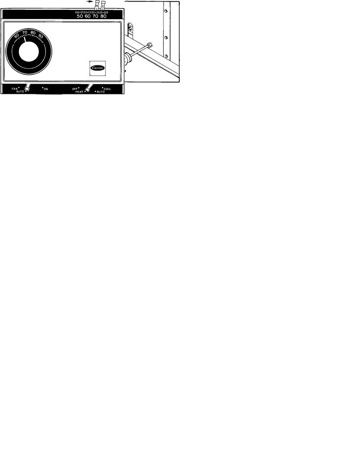
Step 1 Ð Set room thermostat to the lowest temperature setting and set SYSTEM switch to HEAT or AUTO. position.
Step 2 Ð Close the manual gas valve.
Step 3 Ð Turn off the electrical supply to the unit.
Step 4 Ð Remove the burner access panel.
Step 5 Ð Move the control on the gas valve to the OFF position and wait 5 minutes.
Step 6 Ð Move control on gas valve to ON position.
Step 7 Ð Replace the burner access panel.
Manufacturer reserves the right to discontinue, or change at any time, speci®cations or designs without notice and without incurring obligations.
Book |
1 |
4 |
|
PC 111 |
Catalog No. 564-991 |
Printed in U.S.A. |
Form 48TJ-3SO |
Pg 1 |
5-98 |
Replaces: 48TJ-2SO |
Tab |
1a |
6a |
|
|
|
|
|
|
|
|
|
|
|
|
|
|
|
|
|
|
|

Step 8 Ð Turn on the electrical supply to unit.
Step 9 Ð Open the manual gas valve.
Step 10 Ð Set room thermostat selector slightly above room temperature to start unit. The induced-draft combustion air fan will start. Main gas valve will open and main burners should ignite within 5 seconds. If the burners do not light, there is a 22-second delay before another 5-second try. If the burner still does not light, the time delay is repeated. If the burner does not light within 15 minutes, there is a lockout. If burners still do not light, call for service.
Step 11 Ð Set the temperature selector on room thermostat to desired setting.
If the main burners fail to light, or the blower fails to come on, shut down gas heating section and call your dealer for service. Failure to follow these requirements could result in serious personal injury.
TO SHUT UNIT OFF
1.Do not turn off the electrical power to unit without ®rst turning off the gas supply.
2.Never attempt to manually light the main burners on unit with a match, lighter, or any other ¯ame. If the electric sparking device fails to light the main burners, refer to the following shutdown procedures, then call your dealer as soon as possible.
Failure to follow these procedures can result in serious ®re or personal injury.
Refer to Fig. 3 while proceeding with the following steps.
Step 1 Ð Set room thermostat to lowest temperature setting and set SYSTEM switch to OFF position.
Step 2 Ð Close the external manual gas valve.
Step 3 Ð Turn off the electrical power supply to unit.
Step 4 Ð Remove the burner access panel.
Step 5 Ð Move the control on the gas valve to the OFF position.
Step 6 Ð Replace the burner access panel.
Step 7 Ð If unit is being shut down because of a malfunction, call your dealer as soon as possible.
If unit is being shut down because the heating season has ended, restore electrical power to the unit to ensure operation of the cooling system during the cooling season.
Should overheating occur, or the gas supply fail to shut off, shut off the manual gas valve to the unit before shutting off the electrical supply.
Do not use this unit if any part has been under water. Immediately call a quali®ed service technician to inspect the unit and to replace any part of the control system and any gas control which has been under water.
MAINTAINING YOUR UNIT
All maintenance should be handled by skilled, experienced personnel. Your dealer can help you establish a standard procedure.
For your safety, keep the area around the unit clear and free of combustible materials, gasoline, and other ¯ammable liquids and vapors.
To ensure proper functioning of the unit, ¯ow of combustion and ventilating air must not be prevented from reaching the unit. Clearance of at least 3 ft on size 004-007 units and 4 ft on size 008-014 units on the ¯ue and condenser sides and 6 in. on all other sides is required. A clearance of 5 ft is required above the condenser discharge.
ROUTINE MAINTENANCE AND CARE
FOR THE EQUIPMENT OWNER
Consider the following information before maintaining or servicing equipment:
1.TURN OFF GAS SUPPLY AND THEN ELECTRICAL POWER TO YOUR UNIT BEFORE SERVICING OR PERFORMING MAINTENANCE.
2.Do not turn off electrical power to this unit without ®rst turning off the gas supply.
3.When removing access panels or performing maintenance functions inside your unit, be aware of sharp sheet metal parts and screws. Although special care has been taken to reduce sharp edges inside the unit, be extremely careful when handling parts or reaching into the unit.
2
STEP 1 |
STEP 2 |
STEP 3 |
|
|
STEP 4 |
48TJD005-009 |
48TJF004-007 |
|
48TJE004-007 |
|||
|
48TJD012,014 |
||
|
|
||
|
|
48TJE008-014 |
|
|
|
48TJF008-012 |
|
|
|
STEP 5 |
48TJD005-009 |
|
|
48TJE004-007 |
48TJF004-007 |
STEP 7 |
|
48TJD012,014 |
|
|
48TJE008-014 |
|
|
48TJF008-012 |
|
|
STEP 6 |
|
STEP 8 |
STEP 9 |
STEP 10 |
|
Fig. 2 Ð To Light Unit
3
 Loading...