


42GW
|
|
|
R |
QU |
|
|
|
|
|
|
A |
LI |
|
|
|
|
|
E |
|
|
|
||
|
|
T |
|
|
T |
|
|
|
|
|
|
Y |
|
|
|
|
|
S |
|
|
A |
||
E |
G |
I |
|
|
|||
|
|
|
S |
||||
|
|
|
|
|
S |
||
R |
|
|
|
|
|
|
U |
S |
|
|
|
|
|
|
|
' |
|
|
|
|
|
|
R |
D |
|
|
|
|
|
|
A |
|
|
|
|
|
|
N |
|
O |
|
|
|
|
|||
Y |
|
|
|
C |
|
||
|
L |
|
|
E |
|
||
|
|
L |
|
|
|
|
|
|
|
|
|
|
|
|
|
|
|
• |
|
|
1 |
|
|
|
|
I |
|
|
|
|
|
|
|
|
S O 900 |
|
|
||
INSTALLATION MANUAL

42 GW
“Hydronic Global Cassette” Fan Coil Units
Contents |
|
|
Page |
Dimensions and weights ........................................................................ |
2 |
Technical data ........................................................................................ |
3 |
General information ............................................................................... |
4 |
Avoid ...................................................................................................... |
5 |
Installation ............................................................................................. |
6/8 |
Water connections ................................................................................. |
8 |
Motorized valve and control ................................................................... |
9/11 |
Electrical connections ............................................................................ |
11/12 |
Wiring diagram....................................................................................... |
13 |
Fresh air renewal and conditioned air supply to adjacent room ............ |
14/15 |
Maintenance .......................................................................................... |
16 |
Models |
Models |
Models |
Power supply |
|
C = 2-pipe |
C = 2-pipe |
with |
|
|
D = 4-pipe |
D = 4-pipe |
electric heater |
|
|
|
|
|
|
|
42GWC004 |
42GWC004H |
42GWE004 |
|
|
42GWC008 |
42GWC008H |
42GWE008 |
|
|
42GWE010 |
|
|
||
42GWC010 |
42GWC010H |
|
|
|
42GWE012 |
|
|
||
|
|
|
|
|
42GWC012 |
42GWC012H |
42GWE016 |
|
|
42GWC016 |
42GWC016H |
42GWE020 |
|
|
42GWC020 |
42GWC020H |
42GWE004H |
230V ~ 50Hz |
|
42GWE008H |
|
|
||
42GWD004 |
42GWD004H |
|
|
|
42GWE010H |
|
|
||
|
|
|
|
|
42GWD010 |
42GWD010H |
42GWE012H |
|
|
42GWD020 |
42GWD020H |
42GWE016H |
|
|
|
|
42GWE020H |
|
|
|
|
42GWH004 |
|
|
|
|
42GWH008 |
|
|
|
|
|
|
|
|
|
|
|
|
ENGLISH
GB - 1

42 GW
Dimensions and weights
|
|
|
|
|
575 |
|
|
|
|
575 |
|
|
|
|
|
|
|
|
|
|
|
|
|
|
|
100 |
|
|
|
|
|
|
|
|
|
|
|
|
|
|
52 |
|
|
|
|
|
|
|
|
|
|
|
|
|
|
50 |
|
|
|
|
|
|
225 |
|
150 |
120 |
158 |
Ø |
70 |
|
90 |
110 |
155 |
160 |
|
298 |
280 |
Ø |
|
|
|||||||||
|
|
|
|
|
||||||||||
|
|
|
|
|
|
|||||||||
|
42GW |
|
|
440 |
|
|
|
|
720 |
|
|
|
|
|
|
|
|
|
|
|
|
|
|
|
|
|
|||
|
|
|
|
|
|
|
|
550 |
|
|
|
|
||
004 - 008 - 010 |
|
|
|
|
|
|
|
|
|
|
|
|||
|
|
|
|
|
|
|
515 |
|
|
|
|
|
|
|
|
|
|
|
|
Ø 25 |
|
|
|
|
|
|
|
|
|
|
|
|
|
825 |
|
|
|
|
825 |
|
|
|
|
|
|
|
|
|
|
|
|
|
|
|
|
125 |
|
|
|
|
|
|
|
|
|
|
|
|
|
|
|
70 |
|
|
298 |
237 |
|
ø150 |
|
|
120 |
|
|
|
|
88 |
112 |
|
160 |
|
|
|
|
0 |
|
|
|
|
595 |
|
|
|
|
|
|
|
|
|
|
|
|
|
|
|
|
|
|
||
|
|
|
|
62 |
|
|
|
|
|
|
|
|
|
|
|
150 |
|
|
|
|
|
|
|
|
|
|
|
|
|
|
Ø 100 |
|
|
|
|
|
|
|
|
|
|
|
|
|
|
|
|
|
|
|
|
|
|
|
|
|
|
813 |
960 |
|
|
|
|
|
|
25 |
|
|
|
|
|
|
|
|
|
42GW |
|
|
Ø |
|
|
|
|
|
|
|
|
||
|
|
|
|
|
|
|
|
|
|
|
|
|||
012 - 016 - 020 |
|
|
|
|
|
|
|
|
|
|
|
|||
|
42GW |
|
|
004 |
008 |
010 |
012 |
016 |
|
020 |
||||
|
|
Unit |
|
kg |
17.5 |
19 |
19 |
36 |
38 |
|
38 |
|||
Frame/Grille assembly |
|
3 |
3 |
|
3 |
5 |
5 |
|
5 |
|||||
|
|
|
|
|||||||||||
GB - 2 |
|
|
|
|
|
|
|
|
|
|
|
|
|
|

42 GW
Technical data
E N G L I S H
Table I: Nominal data |
|
|
|
|
|
|
POWER INPUT |
|
|
|
|||
|
POWER INPUT |
|
|
|
Models |
Cooling |
|
Heating |
|||||
|
|
|
|
|
|
|
|
|
|
|
|||
|
|
|
|
|
|
|
|
W |
A |
|
W |
A |
|
Models |
|
Cooling |
Heating |
|
|
||||||||
|
|
|
|
|
|
|
|
|
|||||
|
|
|
|
|
|
|
42GWE004 |
70 |
0.30 |
|
1560 |
6.8 |
|
|
|
W |
A |
W |
A |
|
|||||||
|
|
|
42GWH004 |
70 |
0.30 |
|
560 |
2.4 |
|
||||
|
|
|
|
|
|
|
|
|
|||||
42GWC004 |
42GWC004H |
66 |
0.28 |
56 |
0.24 |
|
|||||||
|
42GWE008 |
65 |
0.28 |
|
2555 |
11.1 |
|
||||||
42GWC008 |
42GWC008H |
78 |
0.34 |
68 |
0.29 |
|
|
|
|||||
|
42GWH008 |
65 |
0.28 |
|
555 |
2.4 |
|
||||||
42GWC010 |
42GWC010H |
100 |
0.43 |
90 |
0.39 |
|
|
|
|||||
|
42GWE010 |
94 |
0.40 |
|
2584 |
11.2 |
|
||||||
42GWC012 |
42GWC012H |
97 |
0.42 |
87 |
0.38 |
|
|
|
|||||
|
42GWE012 |
123 |
0.53 |
|
3113 |
13.5 |
|
||||||
42GWC016 |
42GWC016H |
135 |
0.58 |
125 |
0.54 |
|
|
|
|||||
|
42GWE016 |
141 |
0.61 |
|
3131 |
13.6 |
|
||||||
42GWC020 |
42GWC020H |
197 |
0.85 |
187 |
0.81 |
|
|
|
|||||
|
42GWE020 |
233 |
1.00 |
|
3223 |
14.0 |
|
||||||
42GWD004 |
42GWD004H |
66 |
0.28 |
56 |
0.24 |
|
|
|
|||||
|
42GWE004H |
70 |
0.30 |
|
1560 |
6.8 |
|
||||||
42GWD010 |
42GWD010H |
100 |
0.43 |
90 |
0.39 |
|
|
|
|||||
|
42GWE008H |
65 |
0.28 |
|
2555 |
11.1 |
|
||||||
42GWD020 |
42GWD020H |
197 |
0.85 |
187 |
0.81 |
|
|
|
|||||
|
42GWE010H |
94 |
0.40 |
|
2584 |
11.2 |
|
||||||
Note: 230V ~ 50Hz. |
|
|
|
|
|
|
|
||||||
|
|
|
|
|
42GWE012H |
123 |
0.53 |
|
3113 |
13.5 |
|
||
|
|
|
|
|
|
|
42GWE016H |
141 |
0.61 |
|
3131 |
13.6 |
|
Table II: Wire section of connecting cable mm2 |
42GWE020H |
233 |
1.00 |
|
3223 |
14.0 |
|
||||||
|
|
|
|
|
|
|
|||||||
|
|
|
|
|
|
|
|||||||
Models |
L/R |
N/C |
• The power cable to the electrical heaters must be type H07 RN-F. |
|
|
|
|
• The unit power cable must be type H07 RN-F. |
|
from 004 to 020 |
1.0 |
1.0 |
||
|
||||
|
|
|
|
Table III: Technical data of electric heaters (if installed)
|
Mod. |
004 |
|
H004 |
008 |
H008 |
010 |
012 |
|
016 |
|
020 |
Electric heater capacity |
kW |
1.5 |
|
0.5 |
1.5+1.0 |
0.25+0.25 |
1.5+1.0 |
|
2x1 + 2x0.5 |
|
||
Supply voltage (ph) |
V |
230 (1 ph) |
230 (1 ph) |
230 (*) |
230 (1 ph) |
230 (*) |
400 |
|
400 |
|
400 |
|
Max. power input |
A |
6.50 |
|
2.1 |
10.8 |
2.1 |
10.8 |
7.5 |
|
7.5 |
|
7.5 |
Safety thermostat |
|
N° |
1 |
Thermostat with automatic reset ST1 60° C |
|
|
|
|
||||
|
N° |
1 Thermostat with manual reset(electric) ST2 100° C |
|
|||||||||
Power supply cables |
mm2 |
3 x 1.5 |
3 x 1.5 |
3 x 2.5 |
3 x 2.5 |
3 x 2.5 |
5 x 1.5 |
|
5 x 1.5 |
|
5 x 1.5 |
|
Recommended fuse (Type gL) |
A |
8 |
|
8 |
12 |
12 |
12 |
10 |
|
10 |
|
10 |
(*) In areas with a 2 kW limit for single-phase electric heaters it is possible to divide the power supply on two phases and |
|
|||||||||||
neutral of a three phase supply with neutral. |
|
|
|
|
|
|
|
|
|
|
||
Use cable type HO7 RN-F - 4 x 1.5 mm2 - |
400V 2N~ |
|
|
|
|
|
|
|
|
|||
|
|
|
|
|
|
|
|
|
|
|
|
|
IMPORTANT:
The electric heater must always be factory installed (mod. 42GWE/H...).
The use of other eletric heaters is absolutely prohibited.
Failure to follow this safety requirement causes unit damage and voids the warranty.
Table IV: Material supplied
Description |
Q.ty |
Use |
|
|
|
Installation instructions |
1 |
Unit installation |
Fresh air intake baffle |
1 |
Air renewal |
|
|
|
Table V: Operating limits
Water circuit |
Waterside maximum pressure |
Minimum entering water temperature: + 4° C |
||
|
|
|
|
|
|
1400 kPa (142 m w.c.) |
Maximum entering water temperature: + 80° C |
||
|
|
|
|
|
Room air |
|
Minimum temperature: 5° C (1) |
||
|
|
|
|
|
|
|
Maximum temperature 32° C |
|
|
Power supply |
Nominal single phase voltage |
230V ~ 50Hz |
|
60Hz Special Export Market |
|
Operating voltage limits |
min. 198V – max. 264V |
|
min. 187V – max. 253V |
|
Nominal three phase voltage |
400V 3N~ 50Hz |
|
|
|
Operating voltage limits |
min. 342V – max. 462V |
|
|
Notes: (1) If the room temperature can go down to 0° C, it is advisable to empty the water circuit to avoid damage caused by ice (see paragraph on water connections).
Table VI: Accessories
Description |
|
Size / Code |
|
Description |
Size / Code |
|
|
|
004-008-010 |
012-016-020 |
|
|
004-008-010-012-016-020 |
2-pipe valve |
|
42GW9003 |
42GW9007 |
|
Water discharge pump |
40GKX9001 |
4-pipe valve |
|
42GW9004 |
42GW9008 |
|
Control |
42GW9014 |
Primary air |
|
42GW9005 |
42GW9006 |
|
Control |
42GW9015 |
Air disch. closing |
* |
40GK-900---003-40 |
40GK-900---013-40 |
|
Control |
42GW9016 |
|
|
Control |
42GW9017 |
|||
Active carbon filter |
40GK-900---002-40 |
40GK-900---012-40 |
|
|||
Electrostatic filter |
|
40GK-900---001-40 |
40GK-900---011-40 |
|
Control CRC |
33DFS-RM |
Drain pan |
|
42GW9009 |
42GW9010 |
|
Auxiliary board |
42GW9013 |
* Not to be used on units equipped with electric heater (mod.42GWE)
GB - 3

42 GW
General Information
Unit installation
Read this instruction manual thoroughly before starting installation.
•This unit complies with the low-voltage (EEC/73/23) and electromagnetic compatibility (EEC/ 89/336) directives.
•The installation should be carried out by a qualified installer.
•Follow all current national safety code requirements.
In particular ensure that a properly sized and connected ground wire is in place.
•Check that the voltage and frequency of the mains power supply are as required for the unit to be installed; the available power source must be adeguate to operate all other appliances connected to the same line.
Also ensure that national safety code requirements have been followed for the main supply circuit.
•Where necessary, use field-supplied 25 mm I.D. PVC pipe of appropriate length and with the correct thermal insulation for the condensate drain extension.
•After installation thoroughly test system operation and explain all system functions to the owner.
•Use this unit only for factory approved applications: the unit cannot be used in laundry or steam pressing premises.
WARNING:
Disconnect the mains power supply switch before servicing the system or handling any internal parts of the unit.
•The manufacturer declines any liability for damage resulting from modifications or errors in the electrical or water connections.
Failure to observe the installation instructions, or use of the unit under conditions other than those indicated in Table "Operating limits" of the unit installation manual, will immediately invalidate the unit warranty.
•Failure to observe electric safety codes may cause a fire hazard in the event of short circuits.
•Inspect equipment for damage during transport. In case of damage file an immediate claim with the shipping company. Do not install or use damaged units.
•In case of malfunction turn the unit off, disconnect the mains power supply and contact a qualified service engineer.
•Maintenance must only be carried out by qualified personnel.
•All of the manufacturing and packaging materials used for this appliance are biodegradable and recyclable.
•Dispose of the packaging material in accordance with local requiremements.
Choosing the installation site
Positions to avoid:
•Exposure to direct sunlight.
•Areas close to heat sources.
•On damp walls or in positions that may be exposed to water hazard.
•Where curtains or furniture may obstruct free air circulation.
Recommendations:
•Choose an area free from obstructions which may cause uneven air distribution and/or return.
•Consider using an area where installation is easy.
•Choose a position that allows for the clearances required.
•Look for a position in the room which ensures the best possible air distribution.
•Install unit in a position where condensate can easily be piped to an appropriate drain.
GB - 4
42 GW |
|
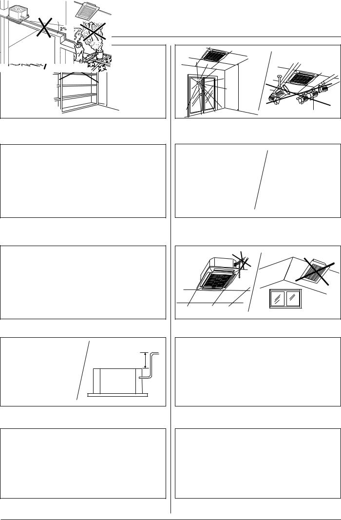
Avoid... |
E N G L I S H |
MAX 3 m |
MAX 3 m |
... any obstruction of the unit air intake or supply grilles. |
... exposure to direct sunshine, when the unit is operating in the |
|
cooling mode; always use shutters or shades. |
|
... positions too close to heating sources which may damage the unit. |
... exposure to oil vapours.
... connecting condensate piping to sewage system drain without appropriate trap. Trap height must be calculated according to the unit discharge head in order to allow sufficient and continuous water evacuation.
... installation in areas with high frequency waves.
MAX. 200 mm
... only partial insulation of the piping.
Non-level installation which will cause condensate dripping.
... ascending sections of condensate drain piping.
These may only be used near the unit with a maximum height difference of 200 mm from the top of the unit.
... flattening or kinking the refrigerant pipes or condensate pipes.
... horizontal sections or curves of condensate drain piping with less |
...slack on electrical connections. |
than 2% slope. |
|
GB - 5
 Loading...