


40RU
Packaged Air---Handling Units
60 Hz
With PuronR (R---410A) Refrigerant
Sizes 25, 28, 30
Installation, Start---Up and
Service Instructions
TABLE OF CONTENTS
SAFETY CONSIDERATIONS . . . . . . . . . . . . . . . . . . . 1
PRE-INSTALLATION . . . . . . . . . . . . . . . . . . . . . . . . . 2
Moving and Storage . . . . . . . . . . . . . . . . . . . . . . . . . . 2
Rigging . . . . . . . . . . . . . . . . . . . . . . . . . . . . . . . . . . . . 2
INSTALLATION . . . . . . . . . . . . . . . . . . . . . . . . . . 2–22
General . . . . . . . . . . . . . . . . . . . . . . . . . . . . . . . . . . . . 2
Uncrating . . . . . . . . . . . . . . . . . . . . . . . . . . . . . . . . . . 2
Accessories . . . . . . . . . . . . . . . . . . . . . . . . . . . . . . . . . 2
Unit Positioning . . . . . . . . . . . . . . . . . . . . . . . . . . . . 11
Unit Isolation . . . . . . . . . . . . . . . . . . . . . . . . . . . . . . 13
Refrigerant and Chilled Water Piping Access . . . . . 13
Refrigerant Piping . . . . . . . . . . . . . . . . . . . . . . . . . . 13
Chilled Water Piping . . . . . . . . . . . . . . . . . . . . . . . . 17
Condensate Drain . . . . . . . . . . . . . . . . . . . . . . . . . . . 18
Fan Motors and Drives . . . . . . . . . . . . . . . . . . . . . . . 18
Power Supply and Wiring . . . . . . . . . . . . . . . . . . . . 19
Connecting Ductwork . . . . . . . . . . . . . . . . . . . . . . . 21
Return-Air Filters . . . . . . . . . . . . . . . . . . . . . . . . . . 21
START-UP . . . . . . . . . . . . . . . . . . . . . . . . . . . . . . . . . 23
SERVICE . . . . . . . . . . . . . . . . . . . . . . . . . . . . . . . 23–36
Panels . . . . . . . . . . . . . . . . . . . . . . . . . . . . . . . . . . . . 23
Fan Motor Lubrication . . . . . . . . . . . . . . . . . . . . . . . 24
Fan Shaft Bearings . . . . . . . . . . . . . . . . . . . . . . . . . . 24
Centering Fan Wheel . . . . . . . . . . . . . . . . . . . . . . . . 24
Fan Shaft Position Adjustment . . . . . . . . . . . . . . . . 24
Individual Fan Wheel Adjustment . . . . . . . . . . . . . . 25
Fan Belts . . . . . . . . . . . . . . . . . . . . . . . . . . . . . . . . . 25
Fan Rotation . . . . . . . . . . . . . . . . . . . . . . . . . . . . . . . 25
Fan Pulley Alignment . . . . . . . . . . . . . . . . . . . . . . . 25
Pulley and Drive Adjustment . . . . . . . . . . . . . . . . . . 25
Condensate Drains . . . . . . . . . . . . . . . . . . . . . . . . . . 25
Return-Air Filters . . . . . . . . . . . . . . . . . . . . . . . . . . 25
Chilled Water Coil Freeze Protection . . . . . . . . . . . 26
Coil Removal . . . . . . . . . . . . . . . . . . . . . . . . . . . . . . 26
Cleaning Cooling Coil . . . . . . . . . . . . . . . . . . . . . . . 26
Cleaning Insulation . . . . . . . . . . . . . . . . . . . . . . . . . 26
Replacing Filters . . . . . . . . . . . . . . . . . . . . . . . . . . . 26
START-UP CHECKLIST . . . . . . . . . . . . . . . . . . 39-40
SAFETY CONSIDERATIONS
Improper installation, adjustment, alteration, service, maintenance, or use can cause explosion, fire, electrical shock or other conditions which may cause personal injury or property damage. Consult a qualified installer, service agency, or your distributor or branch for information or assistance. The qualified installer or agency must use factory-authorized kits or accessories when modifying this product. Refer to the individual instructions package
Follow all safety codes. Wear safety glasses and work gloves. Use quenching cloths for brazing operations and have a fire extinguisher available. Read these instructions thoroughly and follow all warnings or cautions attached to the unit. Consult local building codes and appropriate national electrical codes (in USA, ANSI/NFPA70, National Electrical Code (NEC); in Canada, CSA C22.1) for special requirements.
It is important to recognize safety information. This is the
safety-alert symbol  . When you see this symbol on the unit and in instructions or manuals, be alert to the potential for personal injury.
Understand the signal words DANGER, WARNING, CAUTION, and NOTE. These words are used with the safety-alert symbol. DANGER identifies the most serious hazards which will result in severe personal injury or death. WARNING signifies hazards which could result in personal injury or death. CAUTION is used to identify unsafe practices, which may result in minor personal injury or product and property damage. NOTE is used to highlight suggestions which will result in enhanced installation, reliability, or operation.
40RU
!WARNING
ELECTRICAL SHOCK HAZARD
Failure to follow this warning could cause in personal injury or death.
Before performing service or maintenance operations on unit, always turn off main power switch to unit and install lockout tag. Unit may have more than one power switch.
!WARNING
UNIT OPERATION AND SAFETY HAZARD
Failure to follow this warning could cause in personal injury,death and/or equipment damage.
PuronR (R-410A) refrigerant systems operate at higher pressures than standard R-22 systems. Do not use R-22 service equipment or components on Puron refrigerant equipment.
!WARNING
PERSONAL INJURY AND ENVIRONMENTAL HAZARD
Failure to follow this warning could cause in personal injury or death.
Relieve pressure and recover all refrigerant before system repair or final unit disposal.
Wear safety glasses and gloves when handling refrigerants. Keep torches and other ignition sources away from refrigerants and oils.
!CAUTION
CUT HAZARD
Failure to follow this caution may result in personal injury.
Sheet metal parts may have sharp edges or burrs. Use care and wear appropriate protective clothing, safety glasses and gloves when handling parts and servicing 40RU units.
!CAUTION
UNIT OPERATION HAZARD
Failure to follow this caution could cause equipment damage.
Ensure voltage listed on unit data plate agrees with electrical supply provided for the unit.
PRE-INSTALLATION
1.The power supply (v, ph, and Hz) must correspond to that specified on unit rating plate.
2.The electrical supply provided by the utility must be sufficient to handle load imposed by this unit.
3.Refer to Installation, General section (page 2) and Fig. 1 and Fig. 2 for locations of electrical inlets, condensate drain, duct connections, and required clearances before setting unit in place.
4.This installation must conform with local building codes and with the NEC (National Electrical Code) or ANSI (American National Standards Institute)/NFPA (National Fire Protection Association) latest revision. Refer to provincial and local plumbing or wastewater codes and other applicable local codes.
Moving and Storage - To transfer unit from truck to storage site, use a fork truck. Do not stack units more than 2 high during storage. If unit is to be stored for more than 2 weeks before installation, choose a level, dry storage site free from vibration. Do not remove plastic wrap or skid from unit until final installation.
Rigging - All 40RU Series units can be rigged by using the shipping skid. Units are shipped fully assembled. Do not remove shipping skids or protective covering until unit is ready for final placement; damage to bottom panels can result. Use slings and spreader bars as applicable to lift unit.
INSTALLATION
General - Allow the following clearances for service access and airflow:
SRear: 3 ft (914 mm) [21/2 ft (762 mm) with electric heat accessory]
S Front: 21/2 ft (762 mm)
S Right Side: 31/2 ft (1067 mm) S Left Side: 21/2 ft (762 mm)
For units equipped with an economizer, refer to the accessory installation instructions for additional clearance requirements. Be sure floor, wall, or ceiling can support unit weight (Tables 1A – 1F). See Fig. 1 and Fig. 2 for dimensions.
Uncrating - Move unit as near as possible to final location before removing shipping skid.
Remove metal banding, top skid, and plastic wrap. Examine unit for shipping damage. If shipping damage is evident, file claim with transportation agency. Remove base skid just prior to actual installation.
Check nameplate information against available power supply and model number description in Fig. 3.
NOTE: Be sure to remove the styrofoam shipping pad from the thermostatic expansion valve (TXV). Verify that it has been removed. See Fig. 5.
Accessories - Refer to instructions shipped with each accessory for specific information.
2

Table 1A — 40RUA Physical Data, English — Cooling Units
UNIT 40RUA* |
25 |
|
28 |
|
30 |
NOMINAL CAPACITY (Tons) |
20 |
|
25 |
|
30 |
|
|
|
|
|
|
OPERATING WEIGHT (lb) |
|
|
|
|
|
Base Unit with TXV |
730 |
|
1050 |
|
1062 |
Plenum |
225 |
|
325 |
|
325 |
|
|
|
|
|
|
FANS |
|
|
|
|
|
Qty...Diam. (in.) |
2...15 |
|
2...18 |
|
2...18 |
Nominal Airflow (cfm) |
8000 |
|
10000 |
|
12000 |
Airflow Range (cfm) |
6000 – 10000 |
|
7500 – 12500 |
|
9000 – 15000 |
Nominal Motor Hp (Standard Motor) |
|
|
|
|
|
208/230---3---60 and 460---3---60 |
5.0 |
|
7.5 |
|
10.0 |
575---3---60 |
5.0 |
|
7.5 |
|
10.0 |
Motor Speed (rpm) |
|
|
|
|
|
208/230---3---60 and 460---3---60 |
1745 |
|
1745 |
|
1745 |
575---3---60 |
1745 |
|
1755 |
|
1755 |
|
|
|
|
|
|
REFRIGERANT |
|
|
R---410A |
|
|
Operating charge (lb) |
3.5 |
|
4.5 |
|
5.0 |
(approx per circuit){ |
|
|
|||
DIRECT---EXPANSION COIL |
Enhanced Copper Tubes, Aluminum Sine---Wave Fins |
||||
Max Working Pressure (psig) |
|
650 |
|
|
|
Face Area (sq ft) |
19.88 |
|
|
29.83 |
|
|
24.86 |
|
|||
No. of Splits |
2 |
|
2 |
|
2 |
No. of Circuits per Split |
18 |
|
20 |
|
24 |
Split Type...Percentage |
|
|
Face...50/50 |
|
|
Rows...Fins/in. |
4...15 |
|
|
4...15 |
|
|
4...15 |
|
|||
|
|
|
|
|
|
PIPING CONNECTIONS, |
|
|
|
|
|
Quantity...Size (in.) |
|
|
|
|
|
DX Coil — Suction (ODF) |
2...11/8 |
|
2...13/8 |
|
2...13/8 |
|
|
||||
DX Coil — Liquid Refrigerant (ODF) |
|
|
2...5/8 |
|
|
Steam Coil, In (MPT) |
|
1...21/2 |
|
|
|
Steam Coil, Out (MPT) |
|
1...1/2 |
|
|
|
Hot Water Coil, In (MPT) |
|
1...2 |
|
|
|
Hot Water Coil, Out (MPT) |
|
1...2 |
|
|
|
Condensate (PVC) |
|
|
1...11/4 ODM/1 IDF |
|
|
FILTERS |
Throwaway — Factory Supplied |
||||
Quantity...Size (in.) |
4...16 x 20 x 2 |
|
4...20 x 24 x 2 |
||
|
|||||
4...16 x 24 x 2 |
|
4...20 x 25 x 2 |
|||
|
|
||||
Access Location |
|
|
Either Side |
|
|
|
|
|
|
|
|
STEAM COIL} |
|
|
|
|
|
Max Working Pressure (psig at 260° F) |
|
20 |
|
|
|
Total Face Area (sq ft) |
13.33 |
|
|
15.0 |
|
|
15.0 |
|
|||
Rows...Fins/in. |
1...10 |
|
1...10 |
|
1...10 |
|
|
|
|
|
|
HOT WATER COIL} |
|
|
|
|
|
Max Working Pressure (psig) |
|
150 |
|
|
|
Total Face Area (sq ft) |
13.33 |
|
|
15.0 |
|
|
15.0 |
|
|||
Rows...Fins/in. |
2...8.5 |
|
2...12.5 |
|
2...12.5 |
Water Volume |
|
|
|
|
|
(gal) |
13.9 |
|
|
||
|
14.3 |
|
|||
(ft3) |
|
|
1.90 |
|
|
LEGEND
DX — Direct Expansion
TXV — Thermostatic Expansion Valve
{Units are shipped without refrigerant charge.
}Field installed accessory only.
40RU
3

40RU
Table 1B — 40RUA Physical Data, SI — Cooling Units
UNIT 40RUA* |
25 |
|
28 |
|
30 |
NOMINAL CAPACITY (kW) |
70 |
|
87 |
|
105 |
|
|
|
|
|
|
OPERATING WEIGHT (kg) |
|
|
|
|
|
Base Unit with TXV |
331 |
|
477 |
|
482 |
Plenum |
102 |
|
148 |
|
148 |
|
|
|
|
|
|
FANS |
|
|
|
|
|
Qty...Diam. (mm) |
2...381 |
|
2...457 |
|
2...457 |
Nominal Airflow (L/s) |
3775 |
|
4119 |
|
5663 |
Airflow Range (L/s) |
2831 – 4719 |
|
3539 – 5899 |
|
4247 – 7079 |
Nominal Motor kW (Standard Motor) |
|
|
|
|
|
208/230---3---60 and 460---3---60 |
3.73 |
|
5.60 |
|
7.46 |
575---3---60 |
3.73 |
|
5.60 |
|
7.46 |
Motor Speed (r/s) |
|
|
|
|
|
208/230---3---60 and 460---3---60 |
29.1 |
|
29.1 |
|
29.1 |
575---3---60 |
29.1 |
|
29.3 |
|
29.3 |
|
|
|
|
|
|
REFRIGERANT |
|
|
R---410A |
|
|
Operating charge (kg) |
1.59 |
|
2.04 |
|
2.27 |
(approx per circuit){ |
|
|
|||
DIRECT---EXPANSION COIL |
Enhanced Copper Tubes, Aluminum Sine---Wave Fins |
||||
Max Working Pressure (kPag) |
|
4481 |
|
|
|
Face Area (sq m) |
1.85 |
|
|
2.77 |
|
|
2.30 |
|
|||
No. of Splits |
2 |
|
2 |
|
2 |
No. of Circuits per Split |
18 |
|
20 |
|
24 |
Split Type...Percentage |
|
|
Face...50/50 |
|
|
Rows...Fins/m |
4...591 |
|
|
4...591 |
|
|
4...591 |
|
|||
|
|
|
|
|
|
PIPING CONNECTIONS, |
|
|
|
|
|
Quantity...Size (in.) |
|
|
|
|
|
DX Coil — Suction (ODF) |
2...11/8 |
|
2...13/8 |
|
2...13/8 |
|
|
||||
DX Coil — Liquid Refrigerant (ODF) |
|
|
2...5/8 |
|
|
Steam Coil, In (MPT) |
|
1...21/2 |
|
|
|
Steam Coil, Out (MPT) |
|
1...1/2 |
|
|
|
Hot Water Coil, In (MPT) |
|
1...2 |
|
|
|
Hot Water Coil, Out (MPT) |
|
1...2 |
|
|
|
Condensate (PVC) |
|
|
1...11/4 ODM/1 IDF |
|
|
FILTERS |
Throwaway — Factory Supplied |
||||
Quantity...Size (mm.) |
4...406 x 508 x 51 |
|
4...508 x 610 x 51 |
||
|
|||||
4...406 x 610 x 51 |
|
4...508 x 635 x 51 |
|||
|
|
||||
Access Location |
|
|
Either Side |
|
|
|
|
|
|
|
|
STEAM COIL} |
|
|
|
|
|
Max Working Pressure (kPag at 126° C) |
|
138 |
|
|
|
Total Face Area (sq m) |
1.24 |
|
|
1.39 |
|
|
1.39 |
|
|||
Rows...Fins/m |
1...394 |
|
1...394 |
|
1...394 |
|
|
|
|
|
|
HOT WATER COIL} |
|
|
|
|
|
Max Working Pressure (kPag) |
|
1034 |
|
|
|
Total Face Area (sq m) |
1.24 |
|
|
1.39 |
|
|
1.39 |
|
|||
Rows...Fins/m |
2...335 |
|
2...335 |
|
2...335 |
Water Volume |
|
|
|
|
|
(L) |
52.6 |
|
|
||
|
54.1 |
|
|||
(m3) |
0.052 |
|
0.054 |
|
|
LEGEND
DX — Direct Expansion
TXV — Thermostatic Expansion Valve
{Units are shipped without refrigerant charge.
}Field installed accessory only.
4

Table 1C — 40RUQ Physical Data, English — Heat Pump Units
UNIT 40RUQ* |
25 |
|
|
NOMINAL CAPACITY (Tons) |
20 |
|
|
OPERATING WEIGHT (lb) |
|
Base Unit with TXV |
720 |
Plenum |
140 |
|
|
FANS |
|
Qty...Diam. (in.) |
2...15 |
Nominal Airflow (cfm) |
8000 |
Airflow Range (cfm) |
6000---10000 |
Nominal Motor Hp (Standard Motor) |
|
208/230---3---60 and 460---3---60 |
5.0 |
575---3---60 |
5.0 |
Motor Speed (rpm) |
|
208/230---3---60 and 460---3---60 |
1745 |
575---3---60 |
1745 |
|
|
REFRIGERANT |
R---410A |
Operating charge (lb) |
3.5/3.5 |
(approx per circuit){ |
|
DIRECT---EXPANSION COIL |
Enhanced Copper Tubes, Aluminum Sine---Wave Fins |
Max Working Pressure (psig) |
650 |
Face Area (sq ft) |
19.9 |
No. of Splits |
2 |
No. of Circuits per Split |
2 |
Split Type...Percentage |
Face....50/50 |
Rows...Fins/in. |
4...15 |
|
|
PIPING CONNECTIONS, |
|
Quantity...Size (in.) |
|
DX Coil — Suction (ODF) |
2...11/8 |
DX Coil — Liquid Refrigerant (ODF) |
2...5/8 |
Steam Coil, In (MPT) |
1...21/2 |
Steam Coil, Out (MPT) |
1...11/2 |
Hot Water Coil, In (MPT) |
1...2 |
Hot Water Coil, Out (MPT) |
1...2 |
Condensate (PVC) |
1...11/4 ODM/1 IDF |
FILTERS |
Throwaway — Factory Supplied |
Quantity...Size (in.) |
4...16 x 20 x 2 |
|
4...16 x 24 x 2 |
Access Location |
Right or Left Side |
|
|
STEAM COIL} |
|
Max Working Pressure (psig at 260° F) |
20 |
Total Face Area (sq ft) |
13.33 |
Rows...Fins/in. |
1...10 |
|
|
HOT WATER COIL} |
|
Max Working Pressure (psig) |
150 |
Total Face Area (sq ft) |
13.33 |
Rows...Fins/in. |
2...8.5 |
Water Volume |
|
(gal) |
13.9 |
(ft3) |
1.85 |
LEGEND
DX — Direct Expansion
TXV — Thermostatic Expansion Valve
{Units are shipped without refrigerant charge.
}Field installed accessory only.
40RU
5

40RU
Table 1D — 40RUA Physical Data, SI — Heat Pump Units
UNIT 40RUQ* |
25 |
|
|
|
|
NOMINAL CAPACITY (kW) |
70 |
|
|
|
|
OPERATING WEIGHT (kg) |
|
|
Base Unit with TXV |
326 |
|
Plenum |
44 |
|
|
|
|
FANS |
|
|
Qty...Diam. (mm) |
2...381 |
|
Nominal Airflow (L/s) |
3775 |
|
Airflow Range (L/s) |
2831---4719 |
|
Nominal Motor kW (Standard Motor) |
|
|
208/230---3---60 and 460---3---60 |
3.73 |
|
575---3---60 |
3.73 |
|
Motor Speed (r/s) |
|
|
208/230---3---60 and 460---3---60 |
29.1 |
|
575---3---60 |
29.1 |
|
|
|
|
REFRIGERANT |
R---410A |
|
Operating charge (kg) |
1.59/1.59 |
|
(approx per circuit){ |
||
DIRECT---EXPANSION COIL |
Enhanced Copper Tubes, Aluminum Sine---Wave Fins |
|
Max Working Pressure (kPag) |
4482 |
|
Face Area (sq m) |
1.85 |
|
No. of Splits |
2 |
|
No. of Circuits per Split |
2 |
|
Split Type...Percentage |
Face...50/50 |
|
Fins/m |
591 |
|
|
|
|
PIPING CONNECTIONS, |
|
|
Quantity...Size (in.) |
|
|
DX Coil — Suction (ODF) |
2...11/8 |
|
DX Coil — Liquid Refrigerant (ODF) |
2...5/8 |
|
Steam Coil, In (MPT) |
1...21/2 |
|
Steam Coil, Out (MPT) |
1...11/2 |
|
Hot Water Coil, In (MPT) |
1...2 |
|
Hot Water Coil, Out (MPT) |
1...2 |
|
Condensate (PVC) |
1...11/4 ODM/1 IDF |
|
FILTERS |
Throwaway — Factory Supplied |
|
Quantity...Size (mm) |
4...406 x 610 x 51 |
|
4...406 x 508 x 51 |
||
|
||
Access Location |
Right or Left Side |
|
|
|
|
STEAM COIL} |
|
|
Max Working Pressure (kPag at 126° C) |
138 |
|
Total Face Area (sq m) |
1.24 |
|
Rows...Fins/m |
1...394 |
|
|
|
|
HOT WATER COIL} |
|
|
Max Working Pressure (kPag) |
1034 |
|
Total Face Area (sq m) |
1.24 |
|
Rows...Fins/m |
2...335 |
|
Water Volume |
|
|
(L) |
52.6 |
|
(m3) |
0.052 |
LEGEND
DX — Direct Expansion
TXV — Thermostatic Expansion Valve
{Units are shipped without refrigerant charge.
}Field installed accessory only.
6

Table 1E — 40RUS Physical Data, English — Chilled Water Units
UNIT 40RUS* |
25 |
|
28 |
|
30 |
|
|
|
|
|
|
NOMINAL CAPACITY (Tons) |
20 |
|
25 |
|
30 |
|
|
|
|
|
|
OPERATING WEIGHT (lb) |
|
|
|
|
|
Base Unit |
683 |
|
|
1042 |
|
|
1035 |
|
|||
Plenum |
225 |
|
325 |
|
325 |
|
|
|
|
|
|
FANS |
|
|
|
|
|
Qty...Diam. (in.) |
2...15 |
|
|
2...18 |
|
|
2...18 |
|
|||
Nominal Airflow (cfm) |
8000 |
|
10000 |
|
12000 |
Airflow Range (cfm) |
6000 – 10000 |
|
7500 – 12500 |
|
9000 – 15000 |
Nominal Motor Hp (Standard Motor) |
|
|
|
|
|
208/230---3---60 and 460---3---60 |
5.0 |
|
|
10.0 |
|
|
7.5 |
|
|||
575---3---60 |
5.0 |
|
7.5 |
|
10.0 |
Motor Speed (rpm) |
|
|
|
|
|
208/230---3---60 and 460---3---60 |
1745 |
|
|
1745 |
|
|
1745 |
|
|||
575---3---60 |
1745 |
|
1755 |
|
1755 |
|
|
|
|
|
|
CHILLED WATER COIL |
Enhanced Copper Tubes, Aluminum Sine---Wave Fins |
||||
Max Working Pressure (psig) |
|
435 |
|
|
|
Face Area (sq ft) – Upper |
11.0 |
|
|
15.5 |
|
|
12.4 |
|
|||
Face Area (sq ft) – Lower |
8.3 |
|
12.4 |
|
12.4 |
Rows...Fins/in. |
|
3...15 |
|
|
|
|
|
|
|
|
|
PIPING CONNECTIONS, |
|
|
|
|
|
Quantity...Size (in.) |
|
|
|
|
|
Chilled Water — In. |
2...13/8 ODM |
|
2...21/8 ODM |
|
2...21/8 ODM |
Chilled Water — Out |
2...21/8 ODM |
|
2...21/8 ODM |
|
2...21/8 ODM |
Steam Coil, In (MPT) |
|
|
1...21/2 |
|
|
Steam Coil, Out (MPT) |
|
1...11/2 |
|
|
|
Hot Water Coil, In (MPT) |
|
1...2 |
|
|
|
Hot Water Coil, Out (MPT) |
|
1...2 |
|
|
|
Condensate (PVC) |
|
|
1...11/4 ODM/1 IDF |
|
|
FILTERS |
Throwaway — Factory Supplied |
||||
Quantity...Size (in.) |
4...16 x 20 x 2 |
|
4...20 x 24 x 2 |
||
|
|||||
4...16 x 24 x 2 |
|
4...20 x 25 x 2 |
|||
|
|
||||
Access Location |
|
|
Either Side |
|
|
|
|
|
|
|
|
STEAM COIL} |
|
|
|
|
|
Max Working Pressure (psig at 260° F) |
|
20 |
|
|
|
Total Face Area (sq ft) |
13.33 |
|
|
15.0 |
|
|
15.0 |
|
|||
Rows...Fins/in. |
1...10 |
|
1...10 |
|
1...10 |
|
|
|
|
|
|
HOT WATER COIL} |
|
|
|
|
|
Max Working Pressure (psig) |
|
150 |
|
|
|
Total Face Area (sq ft) |
13.33 |
|
|
15.0 |
|
|
15.0 |
|
|||
Rows...Fins/in. |
2...8.5 |
|
2...12.5 |
|
2...12.5 |
Water Volume |
|
|
|
|
|
(gal) |
13.9 |
|
|
||
|
14.3 |
|
|||
(ft3) |
1.1 |
|
1.90 |
|
|
LEGEND
}Field installed accessory only.
40RU
7

40RU
Table 1F — 40RUS Physical Data, SI — Chilled Water Units
UNIT 40RUS* |
25 |
|
28 |
|
|
30 |
|
|
|
|
|
|
|
NOMINAL CAPACITY (kW) |
70 |
|
87 |
|
|
105 |
|
|
|
|
|
|
|
OPERATING WEIGHT (kg) |
|
|
|
|
|
|
Base Unit |
310 |
|
469 |
|
|
473 |
|
|
|
||||
Plenum |
102 |
|
148 |
|
|
148 |
|
|
|
|
|
|
|
FANS |
|
|
|
|
|
|
Qty...Diam. (mm) |
2...381 |
|
2...457 |
|
|
2...457 |
|
|
|
||||
Nominal Airflow (L/s) |
3775 |
|
4719 |
|
|
5663 |
Airflow Range (L/s) |
2831 – 4719 |
|
3539 – 5899 |
|
|
4247 – 7079 |
Nominal Motor kW (Standard Motor) |
|
|
|
|
|
|
208/230---3---60 and 460---3---60 |
3.73 |
|
5.60 |
|
|
7.46 |
|
|
|
||||
575---3---60 |
3.73 |
|
5.60 |
|
|
7.46 |
Motor Speed (r/s) |
|
|
|
|
|
|
208/230---3---60 and 460---3---60 |
29.1 |
|
29.1 |
|
|
29.1 |
|
|
|
||||
575---3---60 |
29.1 |
|
29.3 |
|
|
29.3 |
|
|
|
|
|
|
|
CHILLED WATER COIL |
Enhanced Copper Tubes, Aluminum Sine---Wave Fins |
|||||
Max Working Pressure (kPag) |
|
2999 |
|
|
|
|
Face Area (sq m) – Upper |
1.02 |
|
1.15 |
|
|
1.44 |
|
|
|
||||
Face Area (sq m) – Lower |
0.77 |
|
1.15 |
|
|
1.15 |
Rows...Fins/m |
3...591 |
|
3...591 |
|
|
3...591 |
|
|
|
|
|
|
|
PIPING CONNECTIONS, |
|
|
|
|
|
|
Quantity...Size (in.) |
|
|
|
|
|
|
Chilled Water — In |
2...13/8 ODM |
|
2...21/8 ODM |
|
|
2...21/8 ODM |
|
|
|||||
Chilled Water — Out |
2...13/8 ODM |
|
2...21/8 ODM |
|
|
2...21/8 ODM |
Steam Coil, In (MPT) |
|
|
1...21/2 |
|
|
|
Steam Coil, Out (MPT) |
|
1...11/2 |
|
|
|
|
Hot Water Coil, In (MPT) |
|
1...2 |
|
|
|
|
Hot Water Coil, Out (MPT) |
|
1...2 |
|
|
|
|
Condensate (PVC) |
|
|
1...11/4 ODM/1 IDF |
|
||
FILTERS |
Throwaway — Factory Supplied |
|||||
Quantity...Size (mm.) |
4...406 x 508 x 51 |
|
4...508 x 610 x 51 |
|||
|
||||||
4...406 x 610 x 51 |
|
4...508 x 635 x 51 |
||||
|
|
|||||
Access Location |
|
|
Either Side |
|
||
|
|
|
|
|
|
|
STEAM COIL} |
|
|
|
|
|
|
Max Working Pressure (kPag at 125° C) |
|
138 |
|
|
|
|
Total Face Area (sq m) |
1.24 |
|
1.39 |
|
|
1.39 |
|
|
|
||||
Rows...Fins/m |
1...394 |
|
1...394 |
|
|
1...394 |
|
|
|
|
|
|
|
HOT WATER COIL} |
|
|
|
|
|
|
Max Working Pressure (kPag) |
|
1034 |
|
|
|
|
Total Face Area (sq m) |
1.24 |
|
1.39 |
|
|
1.39 |
|
|
|
||||
Rows...Fins/m |
2...335 |
|
2..493 |
|
|
2...493 |
Water Volume |
|
|
|
|
|
|
(L) |
52.6 |
|
54.1 |
|
||
|
|
|||||
(m3) |
0.052 |
|
0.054 |
|
||
|
|
|
|
|
|
|
LEGEND
}Field installed accessory only.
8
40RU
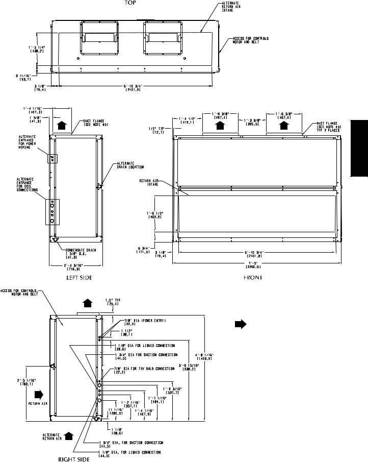
LEGEND
TXV — Thermostatic Expansion Valve
NOTES:
1. |
Dimensions in [ |
] are in millimeters. |
|||
2. |
|
Direction of airflow. |
|||
3. |
Recommended clearance: |
||||
|
• Rear: 3 in. [914 mm] (2 ft, 6 in. [762 mm] |
||||
|
with electric heat accessory) |
||||
|
• Front: 2 ft, 6 in. [762 mm] |
||||
|
• Right Side: 2 ft, 6 in. [762 mm] |
||||
|
• Left Side: 2 ft, 6 in. [762 mm] |
||||
4. |
• Local codes or jurisdiction may prevail. |
||||
Liquid piping not supplied by Carrier. |
|||||
5. |
Duct flange is factory supplied and field |
||||
|
installed. |
|
|
|
|
|
|
|
|
|
|
|
|
UNIT |
|
UNIT WEIGHT |
|
|
|
|
lb (kg) |
||
|
|
|
|
||
|
|
40RUA*25 |
|
730 (331) |
|
|
|
40RUQ*25 |
|
720 (326) |
|
|
|
40RUS*25 |
|
683 (310) |
|
C10722
Fig. 1 - Dimensions – Size 25
9

40RU
LEGEND
TXV — Thermostatic Expansion Valve
NOTES:
1. |
Dimensions in [ ] are in millimeters. |
2. |
Direction of airflow. |
3. Recommended clearance:
• Rear: 3 in. [914 mm] (2 ft, 6 in. [762 mm] with electric heat accessory)
• Front: 2 ft, 6 in. [762 mm]
• Right Side: 2 ft, 6 in. [762 mm]
• Left Side: 2 ft, 6 in. [762 mm]
• Local codes or jurisdiction may prevail. 4. Liquid piping not supplied by Carrier.
5. Duct flange is factory supplied and field installed.
6. 40RUS may require alternate or additional field favricated poping access holes
|
|
|
|
|
|
|
|
|
|
|
|
|
|
|
|
|
|
|
|
|
|
|
|
|
|
|
|
|
|
|
|
|
|
|
|
|
|
|
|
|
|
|
|
|
|
|
|
|
|
|
|
|
|
|
|
|
|
UNIT |
UNIT WEIGHT |
|
|
|
|
|
|
|
|
|
|
|
|
|
|
|
|
|
|
|
|
|
|
|
|
|
|
|
|
lb (kg) |
|
|
|
|
|
|
|
|
|
|
|
|
|
|
|
|
|
|
|
|
|
|
|
|
|
|
|
|
|
|
|
|
|
|
|
|
|
|
|
|
|
|
|
|
|
|
|
|
|
|
|
|
|
|
|
|
|
|
|
40RUA*28 |
1050 (477) |
|
|
|
|
|
|
|
|
|
|
|
|
|
|
|
|
|
|
|
|
|
|
|
|
|
|
|
|
||
|
|
|
|
|
|
|
|
|
|
|
|
|
|
|
|
|
|
|
|
|
|
|
|
|
|
|
|
40RUA*30 |
1062 (482) |
|
|
|
|
|
|
|
|
|
|
|
|
|
|
|
|
|
|
|
|
|
|
|
|
|
|
|
|
||
|
|
|
|
|
|
|
|
|
|
|
|
|
|
|
|
|
|
|
|
|
|
|
|
|
|
|
|
||
|
|
|
|
|
|
|
|
|
|
|
|
|
|
|
|
|
|
|
|
|
|
|
|
|
|
|
|
40RUS*28 |
1035 (469) |
|
|
|
|
|
|
|
|
|
|
|
|
|
|
|
|
|
|
|
|
|
|
|
|
|
|
|
|
40RUS*30 |
1042 (473) |
C10723
Fig. 2 - Dimensions – Sizes 28 and 30
10
1 2 3 4 5 6 7 8 9 10 11 12 13 14 15 16 17 18
4 0 R U A A 2 5 A 1 A 6 – 0 A 0 A 0
_____________ |
____ |
|
|
|
|
|
|
|
|
|
|
|
|||
Model Type |
|
|
|
|
|
|
|
|
|
|
|
|
|
Brand / Packaging |
|
40RU = Carrier Fan Coil |
|
|
|
|
|
|
|
|
|
|
|
|
|
0 = Standard |
|
Puronr R–410ARefrigerant |
|
|
|
|
|
|
|
|
|
|
|
|
|
|
|
|
|
|
|
|
|
|
|
|
|
|
|
Not Used |
|
||
|
|
|
|
|
|
|
|
|
|
|
|
|
|
||
Type of Coil |
|
|
|
|
|
|
|
|
|
|
|
|
|||
|
|
|
|
|
|
|
|
|
|
|
A = Place Holder |
|
|||
A = StandardDXCoil |
|
|
|
|
|
|
|
|
|
|
|
|
|
|
|
|
|
|
|
|
|
|
|
|
|
Service Options |
|
||||
Q = Heat Pump |
|
|
|
|
|
|
|
|
|
|
|
||||
S = Chilled Water Coil |
|
|
|
|
|
|
|
|
|
|
0 = Non-Painted Cabinet |
|
|||
|
|
|
|
|
|
|
|
|
|
|
|
1 = Painted Cabinet |
|
||
|
|
|
|
|
|
|
|
|
|
|
|
|
|||
Refrigerant Options |
|
|
|
|
|
|
|
|
|
|
|
|
|
|
|
|
|
|
|
|
|
|
|
|
|
|
|
|
|
||
A = None |
|
|
|
|
|
|
|
|
|
Not Used |
|
||||
|
|
|
|
|
|
|
|
|
|
|
A = Place Holder |
|
|||
Nominal Tonnage |
|
|
|
|
|
|
|
|
|
|
|
|
|
|
|
|
|
|
|
|
|
|
|
|
|
|
|
|
|
||
25 = 20 Tons |
|
|
|
|
|
|
|
|
Not Used |
|
|||||
28 = 25 Tons |
|
|
|
|
|
|
|
|
0 = Place Holder |
|
|||||
30 = 30 Tons |
|
|
|
|
|
|
|
|
|
|
|
|
|
|
|
|
|
|
|
|
|
|
Design Rev |
|
|||||||
|
|
|
|
|
|
|
|
|
|
||||||
|
|
|
|
|
|
|
|
|
|
||||||
Not Used |
|
|
|
|
|
|
|
– = Catalog Model Number |
|
||||||
A = Place Holder |
|
|
|
|
|
|
|
1 = Design Revision (original) |
|
||||||
Indoor Fan Options |
|
|
|
|
|
|
|
|
|
|
|
|
|
|
|
|
|
|
|
|
|
Voltage |
|
||||||||
1 = Fan Drive and Motor - Low / Motor Efficiency - Standard |
|
|
1 = 575/3/60 |
|
|
|
|
||||||||
2 = Fan Drive and Motor - Med / Motor Efficiency - Standard |
|
|
5 = 208/230/3/60 |
|
|
|
|||||||||
3 = Fan Drive and Motor - High / Motor Efficiency - Standard |
|
|
6 = 460/3/60 |
|
|
|
|
||||||||
|
|
|
|
|
|
|
|
|
|
||||||
|
|
|
|
|
|
|
Coil Options |
|
|||||||
|
|
|
|
|
|
|
|
||||||||
|
|
|
|
|
|
|
A = Al/Cu |
|
|||||||
|
|
|
|
|
|
|
|
|
|
|
|
|
|
|
|
C!0724
Fig. 3 - Model Number Nomenclature
POSITION NUMBER |
|
1 |
|
2 |
3 |
4 |
|
5 |
|
6 |
|
7 |
|
8 |
9 |
10 |
TYPICAL |
|
2 |
|
6 |
1 |
0 |
|
G |
|
1 |
|
2 |
|
3 |
4 |
5 |
|
POSITION |
|
|
|
|
|
DESIGNATES |
|
|
|
|
|
||||
|
|
1−2 |
|
|
|
Week of manufacture (fiscal calendar) |
|
|
|
|||||||
|
|
3−4 |
|
|
|
Year of manufacture (“10” = 2010) |
|
|
|
|||||||
|
5 |
|
|
|
Manufacturing location (G = ETP, Texas, USA) |
|
|
|||||||||
|
|
6−10 |
|
|
|
|
Sequential number |
|
|
|
|
|
||||
C!0725
Fig. 4 - Serial Number Nomenclature
TXV |
COIL |
REMOVE FOAM BLOCK
LEGEND
TXV — Thermostatic Expansion Valve
C10683
Fig. 5 - Foam Block Location
Unit Positioning - The unit can be mounted on the floor for vertical application with return air entering the face of the unit and supply air discharging vertically through the top of the unit. The unit can also be applied in a
horizontal arrangement with return air entering horizontally and the supply air discharging horizontally. When applying the unit in a horizontal arrangement, ensure the condensate drain pan is located at the bottom center of the unit for adequate condensate disposal. See Fig. 6 for condensate connections for each unit position.

 PLUG
PLUG
PLUG |
CONDENSATE |
|
DRAIN |
LEGEND
Accessory Line
Alternate Air Intake and Discharge
Air Intake and Discharge
Note: Maintain recommended clearances per Fig. 1 and Fig. 2
C10684
Fig. 6 - Typical Unit Positioning
40RU
11
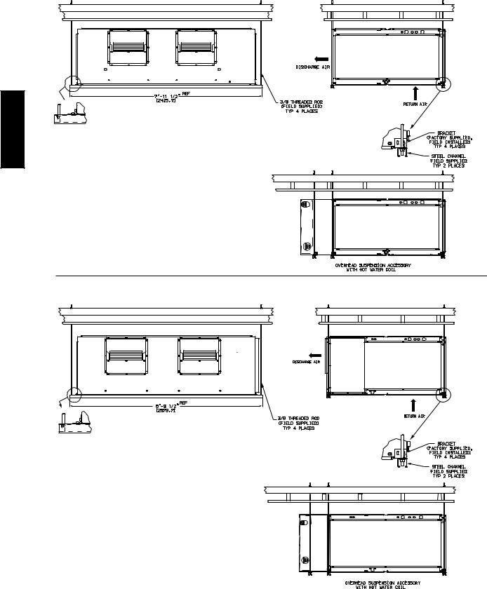
Typical positioning and alternate return air locations are shown in Fig. 6. Alternate return air locations can be used by moving the unit panel from the alternate return air location to the standard return air location. Refer to overhead suspension accessory drawing (Fig. 7) for
preferred suspension technique. The unit needs support underneath to prevent sagging.
IMPORTANT: Do NOT attempt to install unit with return air entering top panel of unit. Condensate will not drain from
unit.
OVERHEAD SUSPENSION ACCESSORY — UNIT SIZE 25
40RU
OVERHEAD SUSPENSION ACCESSORY — UNIT SIZES 28, 30
NOTE: Dimensions in [ ] are millimeters
C10728
Fig. 7 - Preferred Suspension Technique
12
 Loading...