


Z
y
XEL
Multi-Services Access Platform
MSAP2000
Technical Manual
V3R0

ZyXEL MSAP2000
Technical Manual
Manual Version
Product Version
Hardcopy order Information
English V3
V3R0
TM-01-V3R0
ZyXEL Technologies Inc.
WEB site
Email
http://www.ZyXEL.com
:
sales@ZyXEL.com (Sales)
:
support@ZyXEL.com (Technical Support)
ii

MSAP2000
Multi-Service Access Platform
Copyright
Copyright © 2004-2007 by ZyXEL Technologies Inc.
The contents of this publication may not be reproduced in any part or as a wh ole, transcribed,
stored in a retrieval system, translated into any language, or transmitted in any form or by any
means, electronic or mechanical, including photocopying, recordin g, or otherwise, without the
prior written permission of ZyXEL.
Published by ZyXEL Technologies Inc. All rights reserved.
Disclaimer
ZyXEL does not assume any liability arising out of the application or use of any products, or
software described herein. Neither does it convey any license under its patent rights nor the
patent rights of others. ZyXEL further reserves the right to make changes in any products
described herein without notice. This publication is subject to change without notice.
Trademark
MSAP2000 and OptiCoreTM are the trademarks belong to ZyXEL. Other trademarks
mentioned in this publication are used for identification purposes only and may be properties
of their respective owners.
MSAP2000 Technical Manual V3.0 1
About This Manual
This manual applies to the ZyXEL MSAP2000 Release 3.
The main purpose of this manual is to make technical description as clear as
possible to the users planning to use the MSAP2000 as the MSAN equipment in
their existing network or in NGN. Due to the increasing demands on new features
and application, this manual is made to reflect the latest information about
MSAP2000 at the time of editing this manual. Please contact ZyXEL sales to
inquiry the latest information on the information that is not provided in this
manual.
Related Manuals
The related documents consist of the following:
Manual Purpose
MSAP2000 Technical Manual
MSAP2000 User Manual
MSAP2000 Installation Manual
MSAP2000 UI operation Manual
It presents a comprehensive introduction to
the ZyXEL MSAP2000.
It introduces the features, composition,
installation and maintenance of the
MSAP2000.
It covers the service configuration and
installation of the MSAP2000.
It provides all the Menu-driven of the
LCT/Telnet for MSAP2000. It is contained
in the delivery CD-ROM, and no hardcopy
is delivered.
MSAP2000 Technical Manual V3.0 2
Conventions
The manual uses the following conventions:
General conventions
Convention Description
Arial Normal paragraphs are in Arial.
Arial Narrow Warnings, Cautions, Notes and Tips are in Arial Narrow.
Boldface
Courier New
Environmental Protection
This product has been designed to comply with the requirements on
environmental protection. For the proper storage, use and dispo sal of this product,
national laws and regulations must be observed.
Headings are in Boldface.
Terminal Display is in Courier New.
MSAP2000 Technical Manual V3.0 3

Table of Contents
Table of Contents
1. System Introduction ..............................................................................................................1-1
1.1. Overview................................................................................................................1-1
1.2. Key Features .........................................................................................................1-2
1.3. System Architecture ..............................................................................................1-5
1.4. Applications and Services .....................................................................................1-6
1.5. Testing and maintenance......................................................................................1-7
2. System Architecture..............................................................................................................2-1
2.1. Overview................................................................................................................2-1
2.2. SDH ADM..............................................................................................................2-2
2.3. NG DLC.................................................................................................................2-3
2.4. E1 Multiplexer........................................................................................................2-5
2.5. IP DSLAM..............................................................................................................2-6
2.6. Gigabit Switch........................................................................................................2-7
2.7. VoIP Gateway........................................................................................................2-8
2.8. Layer 2 Switch.....................................................................................................2-10
2.9. Digital Cross Connect..........................................................................................2-11
2.10. Flexible Topology ................................................................................................2-12
2.11. Local Craft Terminal............................................................................................2-14
2.12. Network Management System ............................................................................2-15
3. Applications and Services ....................................................................................................3-1
3.1. Fiber to the Building (FTTB)..................................................................................3-1
3.2. Fiber to the Curb (FTTC).......................................................................................3-2
3.3. Fiber to the HOME (FTTH)....................................................................................3-3
3.4. Optical Transportation...........................................................................................3-4
3.5. A One-Stop Solution for the Telephone Service Network.....................................3-5
3.6. Application for Data Leased Line Services............................................................3-7
3.7. Application for DSL Services.................................................................................3-8
3.8. Ethernet over SDH Services..................................................................................3-9
3.9. Microwave radio application................................................................................3-10
4. System Components .............................................................................................................4-1
4.1. Overview................................................................................................................4-1
4.2. Terminal.................................................................................................................4-2
4.3. Shelf.......................................................................................................................4-3
MSAP2000 Technical Manual V3.0 i

Table of Contents
4.4. Common Control Modules.....................................................................................4-6
4.5. Trunk Interface Module..........................................................................................4-8
4.6. COT Network Interface Module.............................................................................4-9
4.7. Subscriber Interface Module................................................................................4-12
4.8. Subscriber End Facilities.....................................................................................4-15
4.9. Indoor Rack .........................................................................................................4-16
4.10. Outdoor Cabinet..................................................................................................4-17
5. System Configuration............................................................................................................5-1
5.1. Slot Chart...............................................................................................................5-2
5.2. Module Capacity....................................................................................................5-3
5.3. 120 Lines A/B wire System Configuration (STM-1)...............................................5-5
5.4. 240 Lines A/B wire System Configuration (STM-1)...............................................5-6
5.5. 360 Lines A/B wire System Configuration (STM-1)...............................................5-7
5.6. 480 Lines A/B wire System Configuration (STM-1)...............................................5-8
5.7. 600 Lines A/B wire System Configuration (STM-1)...............................................5-9
5.8. 720 Lines A/B wire System Configuration (STM-1).............................................5-10
5.9. 960 Lines System Configuration (STM-1)...........................................................5-11
5.10. 1890 Lines System Configuration (STM-1).........................................................5-12
5.11. 120 POTS + 24 ADSL System Configuration (STM-1) .......................................5-14
5.12. 240 POTS + 48 ADSL System Configuration (STM-1) .......................................5-15
5.13. 360 POTS + 72 ADSL System Configuration (STM-1) .......................................5-16
5.14. 480 POTS + 96 ADSL V5 System Configuration (STM-1)..................................5-17
5.15. 480 POTS + 96 ADSL + 6 G.SHDSL V5 System Configuration (STM-1)...........5-18
5.16. 960 POTS + 120 ADSL + 4 G.SHDSL V5 System Configuration (STM-1).........5-19
5.17. 1024 POTS + 96 ADSL + Single-ended V5 System Configuration.....................5-20
5.18. 480 POTS + 180 ADSL NGN System Configuration...........................................5-21
5.19. 900 POTS + 180 ADSL + 2 G.SHDSL NGN System Configuration....................5-22
5.20. 460 POTS + 256 ADSL Single-ended NGN System Configuration....................5-23
5.21. 944 POTS + 192 ADSL Single-ended NGN System Configuration....................5-24
6. System Design .......................................................................................................................6-1
6.1. System Capacity....................................................................................................6-1
6.2. Clock Synchronization...........................................................................................6-3
6.3. Redundancy and Protection Design......................................................................6-4
6.4. Reliability ...............................................................................................................6-6
6.5. Ethernet over SDH Design....................................................................................6-7
6.6. IP DSLAM Design..................................................................................................6-8
7. Product Specification............................................................................................................7-1
7.1. Overview................................................................................................................7-1
MSAP2000 Technical Manual V3.0 ii

Table of Contents
7.2. Main Components .................................................................................................7-2
7.3. Common Shelf.......................................................................................................7-4
7.4. Central Office Power Supply Module (CoPSM).....................................................7-7
7.5. Remote Terminal Power Supply Module (RtPSM)..............................................7-10
7.6. Main Processing Module (MPM) .........................................................................7-13
7.7. Expansion Link Module (ELM).............................................................................7-16
7.8. Expansion Processing Module (EPM).................................................................7-19
7.9. Metallic Line Testing Module (MLTM).................................................................7-22
7.10. V5.2 Processing Module (V5P) ...........................................................................7-25
7.11. Packet Voice Module (PVM)................................................................................7-28
7.12. STM-1 Module (SM1)..........................................................................................7-31
7.13. STM-4 Module (SM4)..........................................................................................7-34
7.14. Optical Interface Module (OIM) ...........................................................................7-37
7.15. Quad E1 Module (QE1M)....................................................................................7-40
7.16. Foreign Exchange Office Module (FXO).............................................................7-43
7.17. Foreign Exchange Station Module (FXS)............................................................7-46
7.18. Foreign Exchange Office Payphone Module (FXO-P)........................................7-49
7.19. Foreign Exchange Station Payphone Module (FXS-P).......................................7-52
7.20. 2W/4W Ear and Mouth Module (2W/4W E&M)...................................................7-55
7.21. G.SHDSL Module (GSH).....................................................................................7-58
7.22. U Interface Network Terminal Module (ISDN-U LUNT).......................................7-62
7.23. ISDN U Interface Line Terminal Module (ISDN-U LULT)....................................7-65
7.24. Nx64 Module for Data Leased Service (N64M)...................................................7-68
7.25. Gigabit Ethernet Module (GbE)...........................................................................7-71
7.26. Optical Gigabit Switch(OGS)...............................................................................7-74
7.27. RT Ethernet over SDH Module (REoSM)............................................................7-77
7.28. COT Ethernet over SDH Module (CEoSM).........................................................7-80
7.29. Ethernet Module (ETH)........................................................................................7-83
7.30. Ethernet Switching Module (ESM).......................................................................7-86
7.31. ADSL2/2+ Access Module (AAM) .......................................................................7-89
7.32. Passive Mux Module(PMM).................................................................................7-92
7.33. G.SHDSL Remote CPE (GSH-R)........................................................................7-95
8. System Management .............................................................................................................8-1
8.1. Overview................................................................................................................8-1
8.2. Local Craft Terminal (LCT)....................................................................................8-2
8.3. Telnet.....................................................................................................................8-3
8.4. OptiCore™ Network Management System (NMS)................................................8-4
MSAP2000 Technical Manual V3.0 iii

Table of Contents
9. NMS Management Functions................................................................................................9-1
9.1. Overview................................................................................................................9-1
9.2. Configuration .........................................................................................................9-2
9.3. Performance Monitoring (PM) ...............................................................................9-3
9.4. Fault Management (FM)........................................................................................9-4
9.5. Maintenance..........................................................................................................9-6
9.6. Security..................................................................................................................9-9
10. System Power and Operation Environment............................................................10-1
10.1. System Power......................................................................................................10-1
10.2. Environment Conditions ......................................................................................10-2
11. System Parameter Specification ..............................................................................11-1
11.1. STM-1..................................................................................................................11-1
11.2. STM-4..................................................................................................................11-2
11.3. Gigabit .................................................................................................................11-3
11.4. E1 ........................................................................................................................11-4
11.5. POTS...................................................................................................................11-7
11.6. Pay Phones .........................................................................................................11-9
11.7. 2W/4W E&M Interface.......................................................................................11-11
1 2 3 4 5 6 7 8 9 10 11
MSAP2000 Technical Manual V3.0 iv

1. System Introduction
Table of Contents
1. System Introduction ..............................................................................................................1-1
1.1. Overview................................................................................................................1-1
1.2. Key Features .........................................................................................................1-2
1.3. System Architecture ..............................................................................................1-5
1.4. Applications and Services .....................................................................................1-6
1.5. Testing and maintenance......................................................................................1-7
MSAP2000 Technical Manual V3.0 i

1. System Introduction
THIS PAGE IS LEFT BLANK
MSAP2000 Technical Manual V3.0 ii

1. System Introduction
1. System Introduction
1.1. Overview
MSAP2000 is a next generation access platform, which supports
triple-play services such as voice, data and video services on a single
shelf. Access network using MSAP2000 is made up of a Central Office
Terminal (COT) and a Remote Terminal (RT) when using SDH trunking;
the COT and RT can be connected by various transmission media, such
as copper wires, optic fibers, or microwave. For NGN network, MS AP2000
can also serve as the single-ended multi-media access gateway for the
triple-play services. The Service Provider’s interface can then be
extended to remote areas such as industrial sites, commercial districts,
and suburban and rural areas, to resolve limitations caused by line
shortage and longer transmission distance.
Not only can MSAP2000 provide service under an existing TDM structure,
it can also offer Service Providers to add-on supplementary features,
based on their own requirements. Modules and software can be installed
based on individual network plans or customer requirements, and existing
TDM networks can seamlessly migrate onto next generation IP network.
MSAP2000’s Remote Terminal (RT) provides several types of user
interfaces, such as PSTN (Narrowband) for POTS and Payphones,
2W/4W E&M analog modules, ISDN for leased line services, G.703 E1
modules, Nx64Kpbs with V.35 interface, G.SHDSL modules, Ethernet
modules for broadband services, and the most up-to-date ADSL2/2+
interface modules. MSAP2000’s flexible system architecture and
modular design makes it an extremely cost-efficient Multiservice Access
Platform. MSAP2000’s comprehensive modular design can assist
Service Providers to deploy their own Access Network within a relatively
short period of time, allowing for the provision of a range of high-speed
and high-quality telecommunication services.
Moreover, MSAP2000’s built-in an Ethernet interface with embedded
SNMP Agent for connection to the SNMP Network Management System.
User-friendly and easy-to navigate GUIs (graphical user interfaces)
provide a full set of OAM&P functions, which include configuration,
maintenance, fault management, performance monitoring, and security
management. This richly integrated Network Management System can
help Service Providers to cut-down on operation costs, as well as provide
a manageable and efficient interface for subscribers to work with.
MSAP2000 allows seamless migration from TDM/ATM network to all IP
network by replacing the network interface modules. Common control
modules, as well as universal shelf all can be re-used to ensure the
effectiveness of the earlier investment.
MSAP2000 Technical Manual V3.0 1-1

1. System Introduction
1.2. Key Features
Multi-service
Provision:
Voice, Data, Video
in one Shelf
Total Solution for
Telephone Voice
Services
Next Generation
DSL Functions
Ethernet over SDH
Cross-connection &
Grooming
Packet Switch
Hybrid Optical
Flexible Topology
Redundancy
Protection
MSAP2000 is an integrated broadband access platform, which
includes several subscriber interfaces within one single shelf, and
can satisfy various customer requirements.
Its interfaces include:
Analog Voice Interfaces: FXS, Payphone, 2W/4W E&M.
Digital Leased Line Interfaces: ISDN BRA/PRA, PABX, Nx64
Kbps, E1, G.SHDSL.
xDSL Interfaces: ADSL, G.LITE, G.DMT, ADSL2/2+, G.SHDSL
Ethernet Interface: 10/100 Ethernet
MSAP2000 provides PSTN and Soft switch voice interfaces,
which include:
(1) FXO: Dual wire PSTN switch analog interface
(2) V5.2 AN: an E1 interface for connection to PSTN V5.2 switch
(3) Soft switch interface: built-in SIP, H.248 and MGCP VoIP
Gateway
The ADSL Access Module (AAM) in MSAP2000 provides
complete IP DSLAM functions.
One module of AAM provides 12 ADSL2/2+ ports, and complies
with ITU-T G.992.1, G.992.2, ANSI T1.413 issue 2, ADSL2
(G.992.3, G.992.4), ADSL2+(G.992.5) and ITU-T G.994.1.
MSAP2000 integrates SDH STM-1 ADM functions. Apart from
providing interfaces for traditional E1 subscribers, it also supports
ITU-T G.7041 and ITU-T X.86 compliant Ethernet over SDH (EoS)
functions, for provision of next generation IP broadband services.
MSAP2000 incorporates the Time Slot Interchange (TSI)
technology. Any input/output port in either the COT or RT can
cross connect at 64 Kbps. Any input/output port at the RT side
can use a 64 Kbit/s time slot basis, to cross connect to any E1
interface on the COT network, to form an E1 signal.
Apart from TDM Switch (TSI) functions, MSAP2000 also provides
Packet switch functions, which support IP network switching
functions, such as IEEE802.1d STP, 802.1p, Port-based &
tag-based VLAN and Static MAC address filtering.
MSAP2000 simultaneously supports two different types of Optical
Trunk Interfaces: SDH STM1/4 and Gigabit Ethernet. All user
interfaces may connect to the COT via a SDH TDM network, or
they can connect to an IP network via a Gigabit Ethernet Packet.
MSAP2000 supports various types of network topologies, such as
Point to Point, Star, Linear, Tree and Branch, Ring. Moreover,
MSAP2000 support both single end and two end configuration to
provide service on access network.
All of MSAP2000’s Common Modules are equipped with
Redundancy functions (1:1, N+1, N:1), to provide double
efficiency and stability during system operation. The 99.99%
in-service quality can be assured. The following modules come
with redundancy functions:
MSAP2000 Technical Manual V3.0 1-2

1. System Introduction
The following modules come with 1:1 redundancy functions:
Power Supply Module: CoPSM, RtPSM
Main Processing Module (MPM)
Expansion Link Module (ELM)
Expansion Processing Module (EPM)
STM-1 Trunk Module (OIM, SM1)
STM-4 Trunk Module (SM4)
V5.1/V5.2 Processing Module (V5P)
The following modules come with N+1/N:1 redundancy functions:
E1 Trunk
Packet Voice module (PVM)
The OIM (SDH STM-1)/SM1/SM4 Optical Interface Modules
provide automatic protection switching (APS) function and 1:1
redundancy protection. The protection time is less than 50ms,
and services will not be interrupted during protection switching.
Local Craft Terminal
(LCT)
The local RS-232 menu-driven management interface allows for
selection of Configuration, Maintenance, Fault Management, and
Security Management functions. In addition, supervisor could
process OAM&P at both COT node and RT nodes. All the
settings will be coordinated automatically and saved in system
database.
MSAP2000 Technical Manual V3.0 1-3

1. System Introduction
Network
Management
System(NMS)
Metallic Line
Testing Module
Built-in Digital
Test Functions
MSAP2000’s OptiCore™, is a highly integrated and easy-to-use
Network Management System that employs user-friendly GUIs
(graphical User Interfaces) to provide a comprehensive set of
OAM&P (Operation, Maintenance and Performance Monitoring)
functions. With this system, the subscriber can remotely monitor,
configure and manage security settings. OptiCore™ NMS can
generate different levels of alarm warnings, and even send alarm
messages to management personnel, based on different service
requirements. The ultimate goal of OptiCore™ NMS is to lower
operation costs, and to help Service Providers efficiently manage
their network, by catering to their specific requirements and
needs.
MSAP2000’s MLTM (Metallic Line Testing Module) can assist
installation and maintenance personnel to instantly confirm Loop
status and performance. MLTM can also connect to the COT
helpdesk for online troubleshooting, via public network or digital
leased lines. When the COT receives a request from the User
Helpdesk, it will test the Carrier System lines, and send the results
back to the Helpdesk. This can help Service Providers save on
cost and manpower for remote testing and maintenance.
MSAP2000 QE1M supports built-in digital testing functions
required by ITU-T O.150 and O.151, and will provide bit-error rate
testing for each digital channel. This function not only eliminates
the need for additional external testing equipment, it can also
ensure service quality.
Seamless Migration
MSAP2000 supports traditional A/B wire switch interface, V5.2
switch interface, and soft switch interface. The capability of
interfaces co-existing allows operator to re-orient part of the
physical voice paths from A/B wire to V5.2 switch or to soft switch.
It also supports to re-orient the co-existing A/B wire interface and
V5.2 interface to soft switch by software configuration. Operator
has no need to un-wrap the physical line and therefore save the
cost of migration from A/B wire to V5.2 to soft switch.
MSAP2000 Technical Manual V3.0 1-4

1. System Introduction
1.3. System Architecture
Scalability
Universal Shelf
Expansion
Modularity
Upgradability
Feature Proof
MSAP2000 is mounted on a 19-inch shelf, which can be installed
on a standard ETSI ETR 300 119 rack. When the subscriber
quantity increases, System capacity can be expanded simply by
adding extra racks. The total System capacity can support up to
7560 lines of telephone interfaces (equal to 63x4 lines of E1
capacity).
MSAP2000’s universal shelf design allows various user interface
modules to be randomly installed in any one of its 1-16 slots. Its
simple Plug-and-Play design provides flexibility in use, and
Service Providers can simply add-on shelves and modules, as
their subscriber quantity and revenue increases.
MSAP2000 when the total lines are required to expand, the
shelves can be linked with ELM and EPM easily. Each node by
the system design can have one main shelf and up to 8 expansion
shelves. The limitation is based on 1+1 requirement of ELM/EPM
link. That will require up to 16 links. And that will use the all
general user slots.
All MSAP2000 modules are designed as plug-in cards with
ejectors, for easy insertion and extraction. Each interface
module can be hot-plugged or unplugged, without affecting the
ongoing service of other modules.
MSAP2000 supports software upgrade functions for various
modules. Operators can connect to the Local Craft Terminal
(LCT) via RS-232, to upgrade any module in the COT or in the RT.
MSAP2000 simultaneously supports Time Division Multiplexing
(TDM) and Internet Protocol (IP) technologies. With these
functions, an existing system shelf can simply re-orientate its
original 2W FXO and V5.2 PSTN switch interface into new Voice
over IP (VoIP) Softswitch, simply by software upgrade or module
expansion. The original Voice Interface Modules (FXS, FXS-P,
2W/4W E&M) can continue to be used, and the System can be
seamlessly migrated from TDM towards a new IP Network
structure, without additional investments on the Service Provider’s
side.
MSAP2000 Technical Manual V3.0 1-5

1. System Introduction
1.4. Applications and Services
Number Exchanging
Between Stations
CO collocation
Construction
Deferral
Application of
Leased Line
Services
Inter-Trunking
Between Stations
Integration of
ADSL and
Ethernet, for
Broadband
Network Services
MSAP2000 is mainly applied towards Access Networks, to
eliminate restrictions caused by line shortage and transmission
distance. MSAP2000 can also be used for Number Exchanging
between stations, CO collocation, construction deferral, and
Inter-trunking between stations, data transmission, and
broadband network deployment.
When the quantity of phone numbers in Station A is insufficient,
yet there are surplus numbers in Station B, MSAP2000 can allow
numbers to be exchanged between Stations, by long-distance
transmission with optic fibers. This will help Service Providers to
save on redundant investment of numbers.
With copper wires, Exchange Stations can only provide service up
to a maximum of 5 kilometers, which means that exchange
stations will need to be set up at every 5-kilometer radius. With
scarcity of land and high construction costs in mind, this hardly
seems such as a feasible option for Service Providers. With
MSAP2000, 7560 lines of subscribers can be transmitted using
one pair of optic fibers. With optic fiber deployment, exchange
stations will only need to be set up at every 30-kilometer radius,
which will help Service Providers to save tremendously on
construction costs.
For remote or suburban areas, where the subscriber quantity has
not yet reached the economic scale required for the building of
exchange stations, MSAP2000 may be installed in airless
environments or in outdoor cabinets, to substitute as an exchange
station or remote Module. This will help Service Providers to
save on construction cost.
MSAP2000 provides E1, ISDN, G.SHDSL and Nx64Kbps ports
with built-in cross connect functions. Data transmission services
can connect directly to the DDN network, without having to link to
the Exchange Server.
MSAP2000 can serve as an inter-trunk between stations. To
enhance the quality of mobile phone services, Service Providers
are continuously setting up mobile base stations, to increase area
coverage for wireless transmission. All mobile base stations
need to transmit their services back to the Exchange Station to be
processed, but MSAP2000 can serve as an inter-trunk between
Exchange Stations and PSTN Stations, by STM-1 optic
transmission via its E1 port.
Service Providers are facing increasing challenges in the fiercely
competitive field of Telecommunications Services. The need for
integrated voice, data and video services are becoming
increasingly urgent. MSAP2000 presents the ideal solution, by
integrating an array of services, to satisfy diverse customer
requirements at a low cost. A Telecommunications Network
installed with MSAP2000 can provide immediate broadband
services by simply adding an ADSL2/2+, or Ethernet interface
module. This will save on the additional cost towards DSLAM
deployment.
MSAP2000 Technical Manual V3.0 1-6

1. System Introduction
1.5. Testing and maintenance
Testing
Digital line testing
Order wire
MSAP2000 is equipped with testing ability for system diagnostic
and can add testing, MLTM, to execute subscriber’s loop quality
examination. Built-in order-wire provides easy front access at
main shelf for maintenance engineers to communicate when
mobile signal is denied or battery is dried.
MSAP2000 supports analog test with MLTM modules. There are
three stages for these analog test items: stage I, stage II, and
stage III. Below is an illustration that describes how to divide the
whole signal path into these three stages.
Stage I starts from COT backplane connection and ends with
switch interface.
Stage II starts from the analog module at COT and ends with the
corresponding one at RT.
Stage III starts from RT backplane connection and ends with the
customer premise equipment (CPE).
Note that the end connection at both stage I and stage III can be
altered in order to determine which section of the loop is having a
problem.
All testing can be executed, and test result, diagnostic,
conclusion, suggestion, alarm can be displayed in both LCT/UI or
in NMS
Digital modules are all built-in with testing function such as local
loopback, remote loop back, line loopback, inward loopback,
payload loopback, facility loopback, terminal loopback. Testing
function can be executed in LCT or in NMS.
Located at the right bottom of each shelf, the RJ-11 connector on
the main shelf provides point-to-point voice channel among the
COT & RTs. Each node has its own four-digit number for other
node to call in. Build-in ring generator allows the engineer at
the other side to attend to task at hand rather than waiting to see
LED status in deciding if there’s any in-coming call by order wire.
MSAP2000 Technical Manual V3.0 1-7

2. System Architecture
Table of Contents
2. System Architecture..............................................................................................................2-1
2.1. Overview................................................................................................................2-1
2.2. SDH ADM.............................................................. .... .... ........ .... ... .... .... .... .... .... .... .2-2
2.3. NG DLC.................................................................................................................2-3
2.4. E1 Multiplexer............................ .... .... .... .... .... .... ........ .... .... .... .... .... ... .... ........ .... .... .2-5
2.5. IP DSLAM..............................................................................................................2-6
2.6. Gigabit Switch........................................................................ .... .... ... .... ........ .... .... .2-7
2.7. VoIP Gateway........................................................................................................2-8
2.8. Layer 2 Switch.....................................................................................................2-10
2.9. Digital Cross Connect..........................................................................................2-11
2.10. Flexible Topology .............................................................. ..................................2-12
2.11. Local Craft Terminal.............................................................................. ..............2-14
2.12. Network Management System ............................................................................2-15
MSAP2000 Technical Manual V3.0 i

2. System Architecture
THIS PAGE IS LEFT BLANK
MSAP2000 Technical Manual V3.0 ii
2. System Architecture
2. System Architecture
2.1. Overview
Multiple Elements
on a Single Shelf
Multiservice –
voice, data, video
Network
Management
System (NMS)
Integrated Testing
Functions
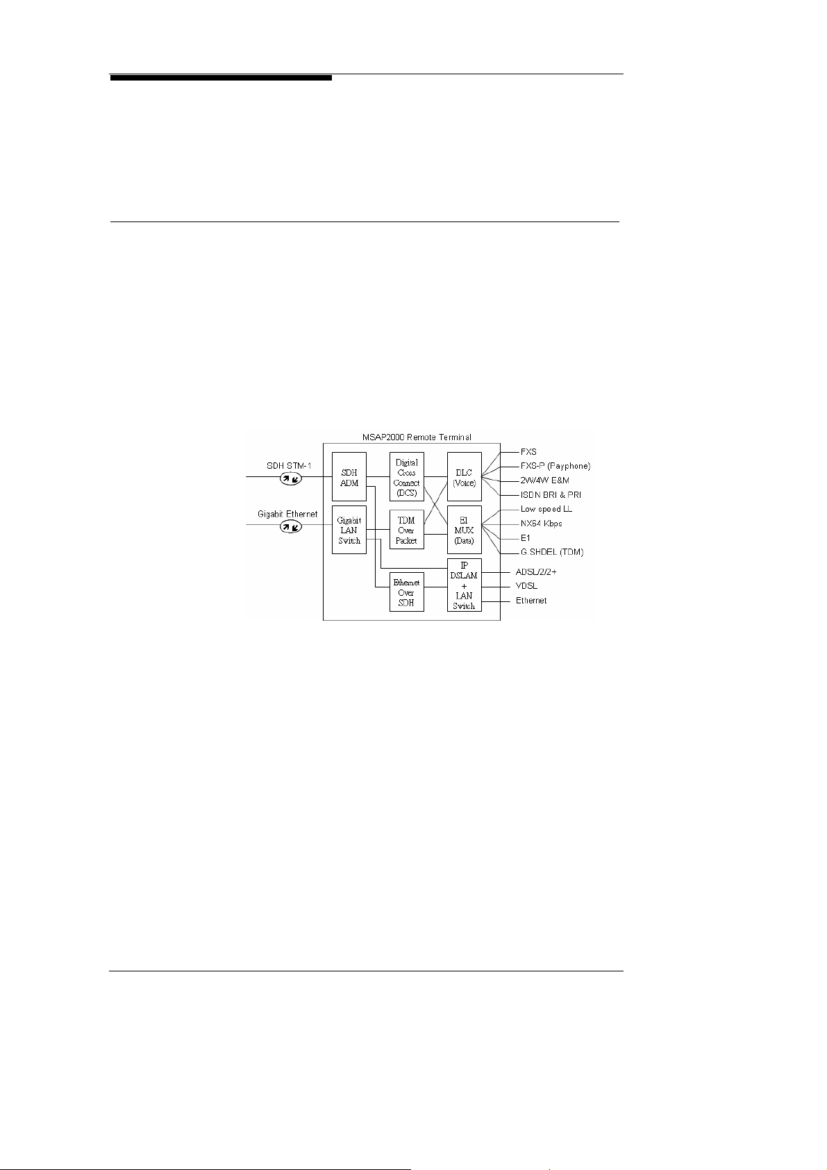
MSAP2000 has integrated various COT interfaces on a single
platform (see Figure 2-A), to simultaneously provide Time-Division
Multiplexing network (TDM) services, as well as Internet Protocol
Packet network (IP Packet Network) services. Apart from
traditional TDM services such as SDH ADM, DLC, Digi tal Cross
Connect (DCS), and E1 MUX, MSAP2000 also provides built-in
next generation devices such as IP DSLAM, Gigabit Switch and
VoIP Gateway.
MSAP2000 is an integrated broadband network access platform,
which provides multiple interfaces within one system, to fulfill all
customer requirements. Its user interfaces include:
Analog voice interfaces: FXS, Payphone, 2W/4W E&M
Digital Leased Line interfaces: ISDN BRA/PRA, Nx64 Kbps,
E1, G.SHDSL.
XDSL interfaces: ADSL G.LITE, G.DMT, ADSL2/2+
Ethernet interface: 10/100 Ethernet
Supports LCT (Local Craft Terminal) menu-driven management
interface, as well as OptiCore™’s graphical network management
system. The NMS provides full OAM&P functions such as
system configuration, performance monitoring, fault management,
and security maintenance.
MSAP2000’s Metallic Line Testing Module (MLTM) can assist
installation and maintenance personnel to swiftly pinpoint
loopback status and quality. Besides MLTM, MSAP2000’s
built-in digital testing functions provide testing patterns which
comply with ITU-T O.150 a nd O .15 1, which ca n be us ed to t est f or
MSAP2000 Technical Manual V3.0 2-1
2. System Architecture
error codes in any channel. Not only does this function help
towards network maintenance and problem elimination, it also can
safeguard service quality.
2.2. SDH ADM
Competitive
Benefits
Tributary Interface
1:1 & Ring
Protection
Ethernet over SDH
In a legacy access network infrastructure, the DLC’s COT (central
office terminal) requires an additional SDH optic multiplexer, to be
able to extend the user interface to the DLC RT (remote terminal),
via an optic fiber network. This type of network infrastructure in
which the SDH multiplexer and DLC are separated, will increase
the burden of equipment and maintenance cost born by Service
Providers. MSAP2000’s integrated platform merges the SDH
ADM optic multiplexer and the DLC System within a single shelf,
bringing the following benefits to Service Providers:
Cuts down on the high amount of E1 interfaces normally
required for SDH and DLC connection, which in turn will lower
facility costs.
Integration of SDH and DLC on a common shelf will save
space in COTs and outdoor cabinets.
An integrated NMS can lower operational costs for Service
Providers.
MSAP2000 supports ITU-T G.707 and G.957 standards. 2340
64Kbps Time Slots can be randomly added & dropped, an d up to
63 E1 interfaces are provided. MSAP2000 also supports the
following Tributary Interfaces:
ITU-T G.703 E1 Interface
ITU-T V.35 NX64 Kbps Interface
ITU-T G.SHDSL Interface
ITU-T G.751 E3 Interface
IEEE 802.3 10/100 Ethernet
MSAP2000 supports automatic protection switching (APS) and
1:1 protection switching. Manual or forced switch protection may
also be conducted, and the protection switch time is less than
50ms. Protection switching will not disrupt ongoing voice
services.
MSAP2000 supports Ethernet over SDH (EoS) which conform to
ITU-T G.7041, to provide next generation IP broadband services.
MSAP2000 Technical Manual V3.0 2-2
2. System Architecture
2.3. NG DLC
Inter-trunking
VF Interface to
PSTN
V5.1/V5.2
Topology
As a legacy Digital Loop Carrier (DLC), MSAP2000 uses
European-standard PCM voice digital coding techniques. Each
COT can be linked to 16 RTs, to provide up to 7560 lines of voice
services. MSAP2000 supports interfaces for POTS, Payphones,
2W/4W E&M, ISDN, E1 digital leased lines, Ethernet, and
G.SHDSL. MSAP2000’s capacity can be exp anded by stacking
shelves upon each other, and depending on individual
requirements, its COT/RT can provide up to 16, 30, 60, 120, 240 ,
360, 480, 600, 720, 960, or 1890 lines capacity.
MSAP2000 uses E1 copper lines, STM-1/STM-4 optic fibers, or
externally added microwave devices to serve as the inter-trunk
between COT and RT. Its inter-trunk is equipped with 1+1
Protection, to ensure transmission stability.
MSAP2000 supports connection of 2-wire Voice Frequency (VF)
interfaces to PSTN switches. MSAP2000 adapts 1:1
non-concentrated operation, to ensure that the caller ID is
transmitted to the subscriber’s telephone.
MSAP2000 supports V5.1/V5.2 interfaces which conform to ITU-T
G.964, G.965, TCN 68-185:1999 standards and has passed IOT
test with the following switch: EWSD/hiE9200, NEAX, NEC,
Lucent, Huawei, ZTE, Ecrisson. The protocol supported include:
LAPV5-EF (Envelope Function), LAPV5-DL (Data Link), V5-Link
Control, V5-BCC (Bearer Channel Connection), V5-PSTN,
V5-Control, V5-Protection. Each V5.2 interface can support up to
16 E1 interfaces, and 480 voice ports, with 1:1 concentration
ratio. MSAP2000’s V5.2 Protocol processor is located on its
V5P module. One V5P module simultaneously supports four
V5.2 switch interfaces; meaning that one MSAP2000 system
provides four V5.2 interfaces; this amounts to 63 E1 capacities,
which will support 7560 voice ports. V5P also supports 1:N
functions.
MSAP2000 supports various network topologies, including
Point-to-Point, Point-to-multipoint, Linear, Tree and Branch, and
Ring.
MSAP2000 Technical Manual V3.0 2-3

2. System Architecture
Digital Leased
Lines
ADSL & Ethernet
MSAP2000 provides various service modules for digital leased
lines, such as ITU-T V.35 Nx64 Kbps, ITU-T G.703 E1, G.SHDSL.
In a Fiber+copper wire environment, MSAP2000 AAM supports
ADSL services. In a Fiber+CAT5 environment, MSAP2000
supports 10/100 Ethernet interfaces.
MSAP2000 Technical Manual V3.0 2-4
2. System Architecture
2.4. E1 Multiplexer
Many Service Providers have already adapted SDH as the
backbone of their fiber networks, and are providing E1
transmission interfaces via SDH ADM. Each subscriber has
different bandwidth and interface requirements, so an E1
bandwidth is usually segmented to fulfill different requirements.
Because several subscribers are sharing an E1 bandwidth, an E1
multiplexer will need to be installed at each client end.
MSAP2000 has integrated SDH ADM and E1 Multiplexer onto a
single shelf, which not only conserves space, but will also
standardize network management, and reduce hardware
investment costs. Moreover, MSAP2000 can also function as a
traditional E1 Multiplexer, to provide 2W/41 E&M, ISDN BRI,
Nx64 Kbps, and Fractional E1 services together with the Service
Provider’s existing SDH optic fiber facilities.
MSAP2000 Technical Manual V3.0 2-5
2. System Architecture
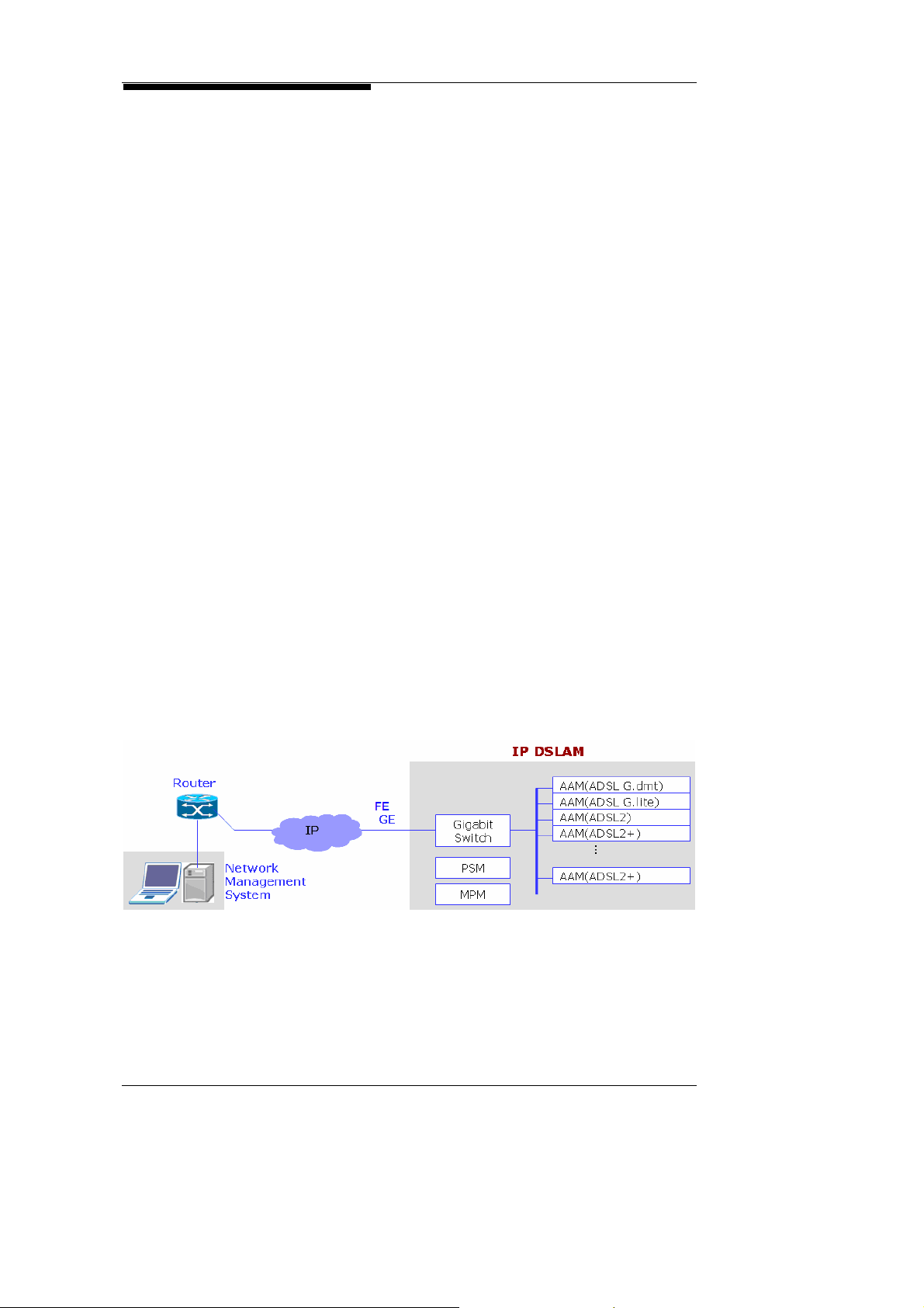
2.5. IP DSLAM
IP DSLAM
xDSL Functions
L2 Switch
Features
MSAP2000 supports IP DSLAM functions. The uplink to BBRAS
can be achieved by GbE module through FE or GE interfaces Its
AAM (ADSL Access Module) provides 12 lines of ADSL2/2+; one
shelf provides up to a maximum of 96 ADSL2/2+ interfaces, and a
single shelf supports both POTS and ADSL services. One
MSAP2000 system can provide up to 576 ADSL user interfaces
and 16000 MAC addresses. MAC address can be assigned to
individual port to support MAC anti-spoofing. VLAN setting can be
up to 1024 for PVC, individual port, IP source address and IP
destination. VLAN translation as well as VLAN stacking ar e also
supported. Ethernet bridging is realized by 802 .1d stan dard and
link aggregation is done according to 802.3 a & 802.3.d while flow
control is designed based on 802.3x. STP, RSTP and MSTP are
supported in spanning tree and static IP address can be
supported as long as the setting in BRAS and in CPE are
identical. QoS based on 802.1p can be provisioned for
individual port along with VLAN, IP SA/DA, IP TOC/DSCP
parameters, which allows policing and shaping traffic by port.
DHCP as well as DHCP filtering can be enabled or disabled to
support access control list by order of port, MAC address, and IP
address. Multicast supports bridged mode with IGMP v1/v2
protocol and IGMP snooping enabled. Total number of multicast
group can suppress 256.
MSAP2000’s ADSL Access Module (AAM) supports ADSL
G.LITE, G.DMT, ADSL2, and ADSL2+.
GbE and REoSM/CEoSM can also support Layer 2 switch
functions, including MAC filtering, 802.1q VLAN Tagging,
802.1p QoS with priority queuing, 802.1w RSTP, IGMP v1 & v 2
snooping, DHCP, SNMP v1 & v2 and RMON.
MSAP2000 Technical Manual V3.0 2-6
2. System Architecture
2.6. Gigabit Switch
Layer 2 Switch
Functions
AAM +
Optical Gigabit
Ethernet
Migration towards IP is the future trend of network development.
MSAP2000 has incorporated the Optical Gigabit Ethernet (GbE)
Module, to elevate its optical trunking to 1000 Mbps bandwidth.
GbE’s built-in L2 Switch functions will support new broadband IP
services.
The Ethernet Switch Module (ESM) supports 8 10/100 Mbps
Ethernet interfaces, and provides Packet Switch functions, such
as IEEE802.1d STP, 8021p, Port-based & tag-based VLAN, and
Static MAC address filtering.
The GbE Module supports 16 x 100/1000BaseT Ethernet Links,
and can connect to the AAM Module using the backplane high
speed bus, to form a complete IP DSLAM structure. This module
can support up to 192 lines of ADSL2/2+.
MSAP2000 Technical Manual V3.0 2-7
2. System Architecture
2.7. VoIP Gateway
VoIP Gateway
VoIP Gateway
at COT
Along with the widespread usage of the Internet, VoIP
development has become an inevitable trend. Service Providers
are cutting down on PSTN switch usage, and turning towards
planning and deployment for Softswitch. To fulfill the needs of a
next generation network structure, MSAP2000’s VoIP Gateway
supports VoIP Protocols such as SIP and H.248. MSAP2000
can connect to Softswitch directly through the IP network, to
provide VoIP s ervices. With MSAP2000’s Vo IP Gateway, ther e
will be no problems with transitions from PSTN to Softswitch,
even if the receiving end has not yet been upgraded.
MSAP2000 provides a complete migration Roadmap for CAS,
CCS, and Softswitch, which will fulfill all upgrading requirements
for Service Providers.
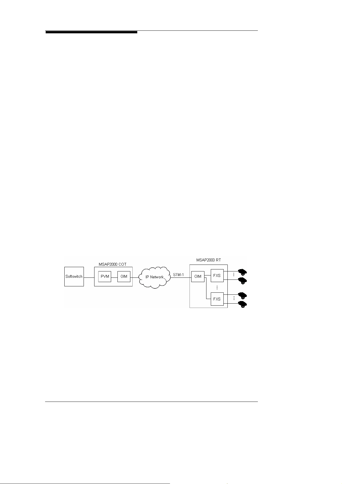
Before a VoIP Service Network is fully deployed, Service
Providers will still need to provide TDM DLCs and Switches, for
existing voice clients. After migration to an IP network however,
Service Providers will face severe investment losses, if they opt to
discard TDM DLC, and change their PSTN switches to
Softswitch. MSAP2000 can so lve this pr ob lem by functionin g as
a DLC, eliminating restrictions posed by line shortage, limited
transmission distance, and growing voice service demands.
When Service Providers are ready to transit to Softswitch, all they
need to do is add a Packet Voice Module (PVM) to their alr eady
deployed MSAP2000 COT, and connection to Softswitch can be
established without discarding RTs or any other existing
equipment. MSAP2000 offers a seamless migration solution,
which allows Service Providers to cut down on cost and increase
revenue by retaining 80% of their existing facilities.
MSAP2000 Technical Manual V3.0 2-8
2. System Architecture
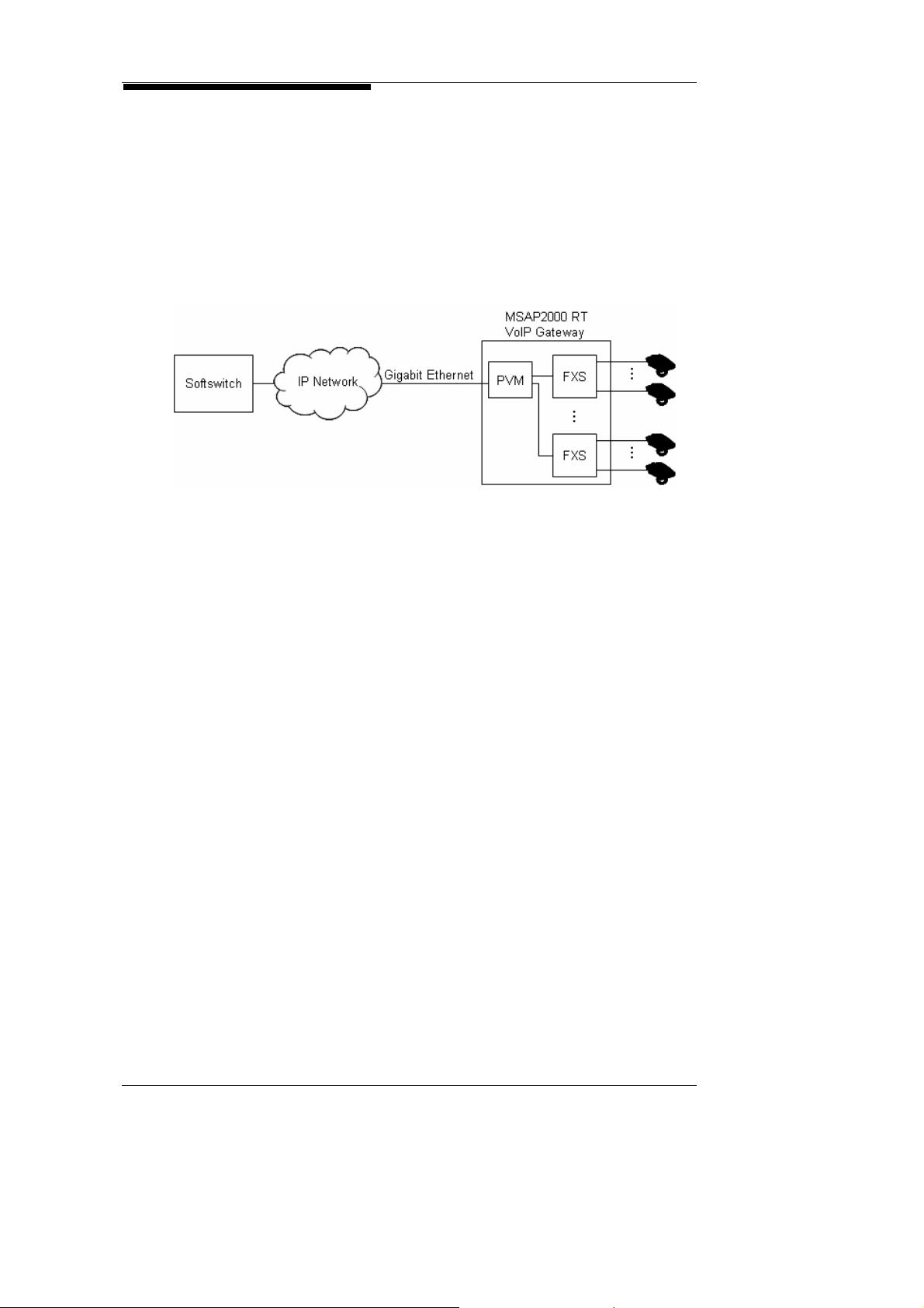
VoIP Gateway
at RT
Service Providers with no existing facilities can easily deploy a
brand new next generation IP network. In an overall IP
environment, MSAP2000 can be installed in building basements
to serve as a high density VoIP Gateway, and provide VoIP
services via a FTTB optic network. With GbE, the optical gigabit
interface allows the migration to the NGN network. One
MSAP2000 will serve all units in the building, without any impact
to subscribers.
MSAP2000 Technical Manual V3.0 2-9
2. System Architecture
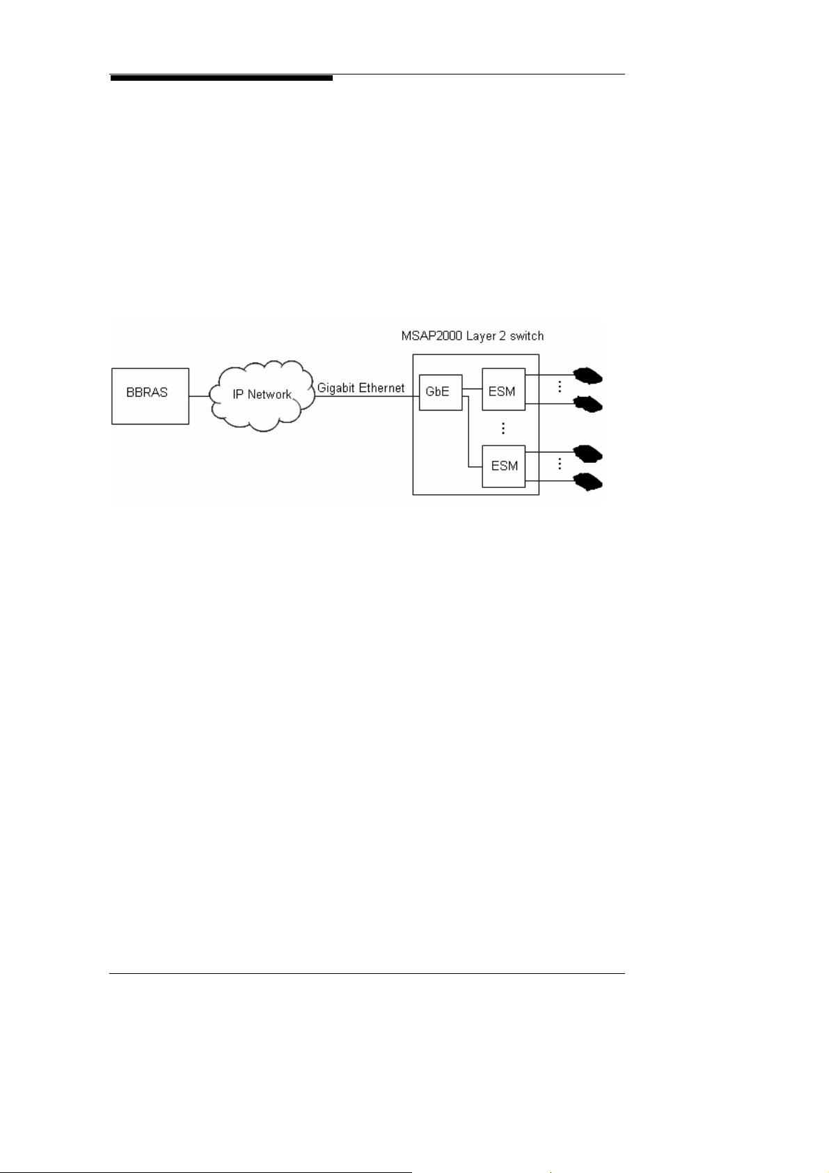
2.8. Layer 2 Switch
Layer 2 switch
Layer 2 switch
at RT
MSAP2000 can connect to Edge router to provide Ethernet
leased line with the layer 2 switch module ESM.
Service Providers can easily provide FE leased line service with
selectable bandwidth to enterprise in office building without extra
CPE or switch. In an over all IP envir onment, MSAP2000 can be
installed in building basements to serve as a high density Laye r 2
switch, and provide VoIP services via a FTTB optic network.
MSAP2000 Technical Manual V3.0 2-10

2. System Architecture
2.9. Digital Cross Connect
Concentration
Cross-connection
Grooming
MSAP2000’s Timeslot Interchange technology is based on VLSI,
to incorporate built-in Digital Cross Connect (DCS) functions into
its system platform. MSAP2000 can pr ovide up to a maximum
of 2430 x 2430 64Kbps of Digital Cross Connect. This function
can greatly reduce the need for procuring additional DCS
equipment.
MSAP2000 provides 1:1 service, when the COT is connected to
the Exchange Switch via a dual-wire FXO interface. 1:N
concentration service is provided when the COT is connected to
the Exchange Switch via a V5.2 E1 interface. The concentration
ratio can be configured through software settings. Moreover,
the concentration could be done on either COT or RT. If the
concentration is done at RT site, it could save trunk bandwidth.
MSAP2000 employs the Time Slot Interchange (TSI) technology
to increase broadband efficiency. All Channel Assignments
(CA) are set at a 64Kbps timeslot, so that any input or output
ports from either the COT or RT can cross connect at 64 Kbps.
For example, any RT FXS, FXS-Payphone or E1 leased line
interface can be cross connected to its counterpart at the COT
end.
V.35 and E1 interface signals from any RT input/output port,
including FXS, FXS-P, 2W/4W E&M, QE1M and STU-R, can be
groomed to any COT E1 interface at a 64Kbit/s timeslot. RT
Ethernet interfaces (ETF) and STU-R Ethernet Interface Signals
can also be connected to the COT’s ETH.
MSAP2000 Technical Manual V3.0 2-11

2. System Architecture
2.10. Flexible Topology
Point to Point
Point to
multipoint
(Star)
MSAP2000 supports various types of network topologies, such as
Point-to-Point, Star, Linear, Tree & Branch, and Ring. With its
expansible shelves, and plug & play modular design, MSAP2000 offers
tremendous operational flexibility for Service Providers.
A COT is connected directly to a RT. This is th e most common type of
network structure for access networks. 1+ 1 Protection is provided for
the COT and RT. For P-2-P topology, one RT is needed.
MSAP2000 uses the Time Slot Interchange (TSI) technology, to set all
Channel Assignments (CA) at a 64 Kbps time slot base, to provide
maximum bandwidth efficiency. Any input or output ports in either the
COT or RT can cross connect at a basis of 64 Kbps. In star topology,
one node can connect to 5 RTs.
Linear
Tree and
Branch
MSAP2000 Technical Manual V3.0 2-12
In a linear topology, a COT installed in the central exchange station can
provide linkage to up to 16 RTs. The transmission media used to
connect COTs and RTs are varied, ranging from optic fibers, to copp er
wires, to wireless transmission. For linear topology, eight RTs can be
cascaded.
MSAP2000 supports tree and branch topologies. Each combination set
can support up to 16 RTs, and Optical Interface Modules (OIM) or
multiple E1 interfaces will serve as the trunking i nterf ace a mon g the RTs.

2. System Architecture
Ring
MSAP2000 supports ring topology, with automatic protection switching
(APS), . Protection switching time is under 50ms, and will not cause
interruption to services. Maxinum of 8 nodes are supported in each ring.
MSAP2000 Technical Manual V3.0 2-13

2. System Architecture
2.11. Local Craft Terminal
MSAP2000 can be linked to PCs via its RS-232 interface, to support
field operators to locally conduct OAM&P (Operation, Administration,
Maintenance and Provisioning) functions.
Besides short-distance connection via RS-232, MSAP2000’s LAN port
can also connect to remote site computers via Telnet, for system
management.
MSAP2000’s menu mode includes the following items for
management:
Configuration
Performance
Fault
Maintenance
Security
Administration
Logout
Help
To protect System security, LCT requires Username and Password
authentication. The default username is “admin”, and the default
password is “0000”. It is recommended that the user s hould change
the default password during initial login, and then create new
username and password with different privilege if necessary.
MSAP2000 Technical Manual V3.0 2-14

2. System Architecture
2.12. Network Management System
OptiCore™ Features
System Platform
Telecommunication
Standards
Graphical User
Interface (GUI)
Database
OptiCore is a Network Management System (NMS) developed
solely by ZyXEL
port provides connection to the NMS. Operators may use
OptiCore’s GUI (Graphical User Interface) to remotely operate
MSAP2000, and conduct various operation and management
functions. After the COT receives commands from OptiCore via
SNMP MIB, it will dispatch the commands to the various RTs, for
system management.
Provides cross-platform functions, so that Server and Client
can retain compatibility, despite use of different operation
systems.
Provides individual operation interfaces, based on different
user authorization levels and administrative settings.
Provides a Network Management hierarchy structure.
Provides comprehensive functions for management of System
settings, performance, fault, maintenance and security.
Compatible with several Database Servers.
Compatible with various types of Java Application Servers,
with no need for additional Patch files.
Supports multi-languages. Text files can be uploaded and
easily translated.
OptiCore™’s design is based on Java Application Platform
design, and its function is to serve as a cross-platform,
multi-function NMS. The OptiCore™ NMS platform can
simultaneously control 300 MSAP2000s, and provide
simultaneous access to up to 10 operators.
Adapts SNMP V2c Telecommunication Standards. OptiCore™
is compatible with SNMPV3, CORBA, TL1, and CMIP standards,
and employs FTP or TFTP to upload and download software and
parameters.
Windows-based Graphical User interfaces (GUI) are developed
using JAVA, and the GUIs represent realistic and flexible
management tools, that can be easily recognized by any
subscriber. The GUI is basically a step-by-step guide, that can
lead operators through the MSAP product series, and help
Service Providers to save on extra training costs.
All system parameters are stored within the database; the
administrator may make copies, and update or recover software
and parameters.
, for the MSAP2000 Sys tem. Th e COT’s RJ-45
刪除: ZyFLEX
MSAP2000 Technical Manual V3.0 2-15

2. System Architecture
THIS PAGE IS LEFT BLANK
MSAP2000 Technical Manual V3.0 2-16

3. Application and Services
Table of Contents
3. Applications and Services ....................................................................................................3-1
3.1. Fiber to the Building (FTTB)..................................................................................3-1
3.2. Fiber to the Curb (FTTC).......................................................................................3-2
3.3. Fiber to the HOME (FTTH)....................................................................................3-3
3.4. Optical Transportation...........................................................................................3-4
3.5. A One-Stop Solution for the Telephone Service Network.....................................3-5
3.6. Application for Data Leased Line Services............................................................3-7
3.7. Application for DSL Services.................................................................................3-8
3.8. Ethernet over SDH Services..................................................................................3-9
3.9. Microwave radio application................................................................................3-10
MSAP2000 Technical Manual V3.0 i

3. Application and Services
THIS PAGE IS LEFT BLANK
MSAP2000 Technical Manual V3.0 ii

3. Application and Services
3. Applications and Services
3.1. Fiber to the Building (FTTB)
When MSAP2000 is installed in building basements, community
guardrooms, or telecommunication server rooms, it can provide
a packaged service which includes voice services, digital leased
lines and broadband network services, to the User group. With
linkage provided by optic fibers, all voice, data and broadband
connections can be sent to the COT end, and put through to
exchange devices. MSAP2000’s FTTB application is just like
having a COT installed within the User’s building, which can
save on the cost for server room construction. A FTTB network
infrastructure can shorten last mile distance, and greatly
increase ADSL bandwidth.
MSAP2000 Technical Manual V3.0 3-1

3. Application and Services
3.2. Fiber to the Curb (FTTC)
As shown in the diagram below, when an environment can no
longer provide server room space for MSAP2000 installment,
MSAP2000 can alternatively be installed in a curbside cabinet.
Curbside cabinets can connect the subscriber to the COT, using
optic fibers instead of copper wires. Curbside cabinets can
also effectively shorten service distance, thus enlarging the
xDSL bandwidth. Moreover, MSAP2000’s SDH features also
support various topologies, as well as switch protection
functions, which allow MSAP2000 to provide an efficient
bandwidth and superior service quality.
MSAP2000 Technical Manual V3.0 3-2

3. Application and Services
3.3. Fiber to the HOME (FTTH)
As triple play services grow, providing higher bandwidth to the
subscribers is a must. The latest development on IEEE 802.3ah
is becoming more mature. And the content providers are
providing more and more add-on services never shown before.
MSAP2000 allows the migration for the PON solution for the
FTTH solution as shown below.
0
0
P
P
oI
oI
V
V
D
O
M
/
V
T
e
P
c
I
i
f
f
O
l
a
r
t
n
e
C
0
2
P
A
S
M
k
r
o
w
t
e
N
P
I
MSAP2000 Technical Manual V3.0 3-3

3. Application and Services
3.4. Optical Transportation
Wireless service providers are ever-searching for solutions
which can enlarge the coverage area of wireless base stations,
as well as cut down on repeated investments of transmission
equipment. MSAP2000 presents the most ideal solution for
mobile transmission efficiency, in that its ring-net protection
mechanism safeguards service quality and that MSAP2000’s
IP-orientated features will allow for immediate and efficient
migration, once wireless base stations are upgraded to IP
networks. This allows service providers to save on investment
and operation costs, and will boost their competitive superiority.
MSAP2000 Technical Manual V3.0 3-4

3. Application and Services
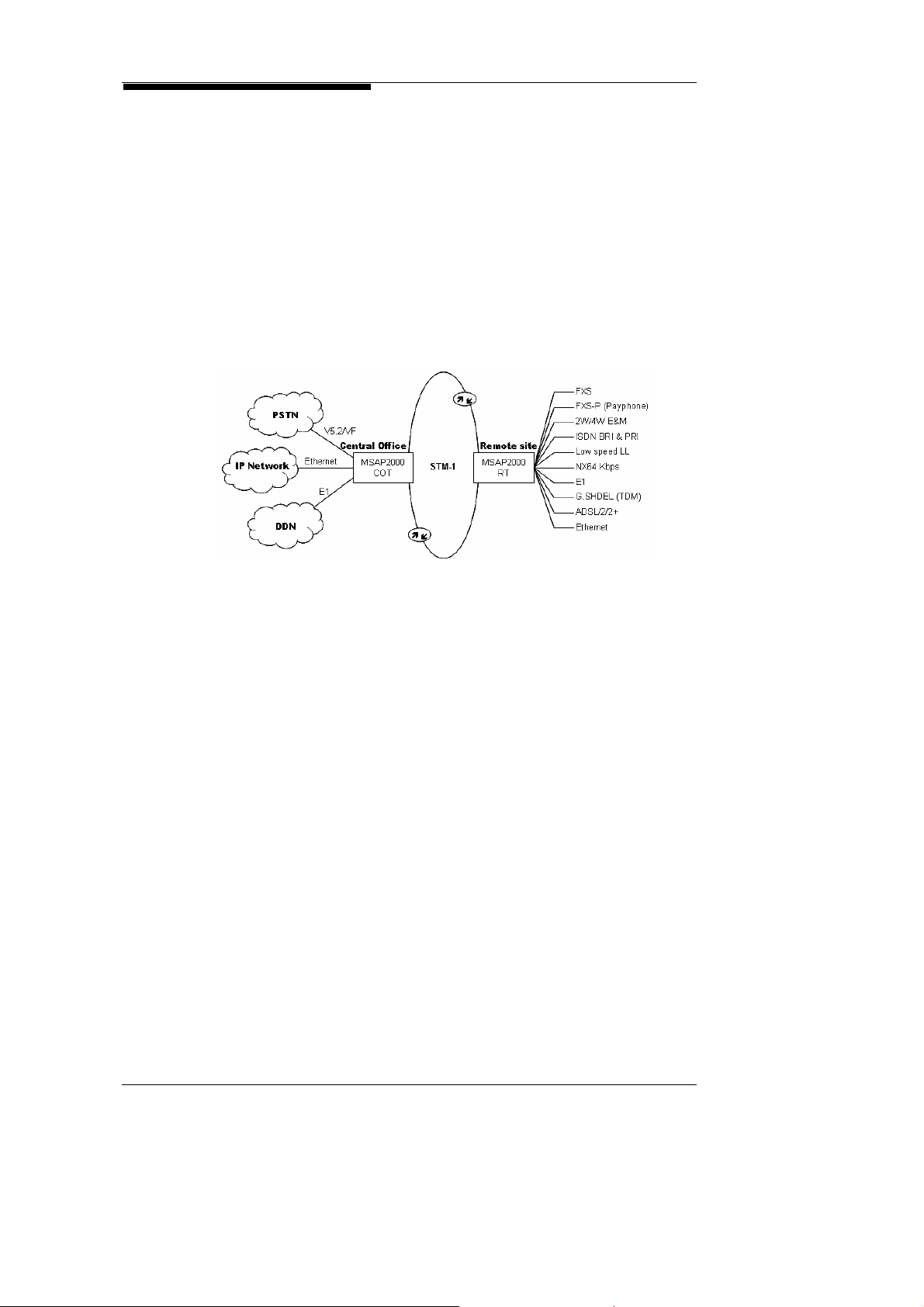
3.5. A One-Stop Solution for the Telephone Service Network
VF Interface to PSTN
MSAP2000 is a next generation Digital Loop Carrier (NGDLC),
which supports various types of telephone network
technologies. MSAP2000 can provide connection to legacy
PSTN exchange devices via dual-wire analog voice FXO or
V5.2 interfaces, and its Packet Voice Module (PVM) provides
Softswitch connections as well. MSAP2000’s modular design
allows service providers to flexibly expand their system capacity
at their own pace, which will help to save on operational cost, in
the initial stages of business startup. With a STM-1/E1 trunk
interface and V5.2 switch interface, MSAP2000 can provide up
to 7560 lines of voice services. MSAP2000 also supports
PSTN and Softswitch voice interfaces, which include:
(1) Dual-wire PSTN exchange interface: FXO
(2) E1 CCS exchange interface: V5P (V5.2 Protocol Processing
Module)
(3) Softswitch interface: PVM (Packet voice module)
MSAP2000 supports connection between Dual-wire Voice
Frequency (VF) interfaces and traditional PSTN exchange
servers. To ensure that the Caller ID is transmitted to
subscriber phones, MSAP2000 delivers 1:1 non-concentrated
operation.
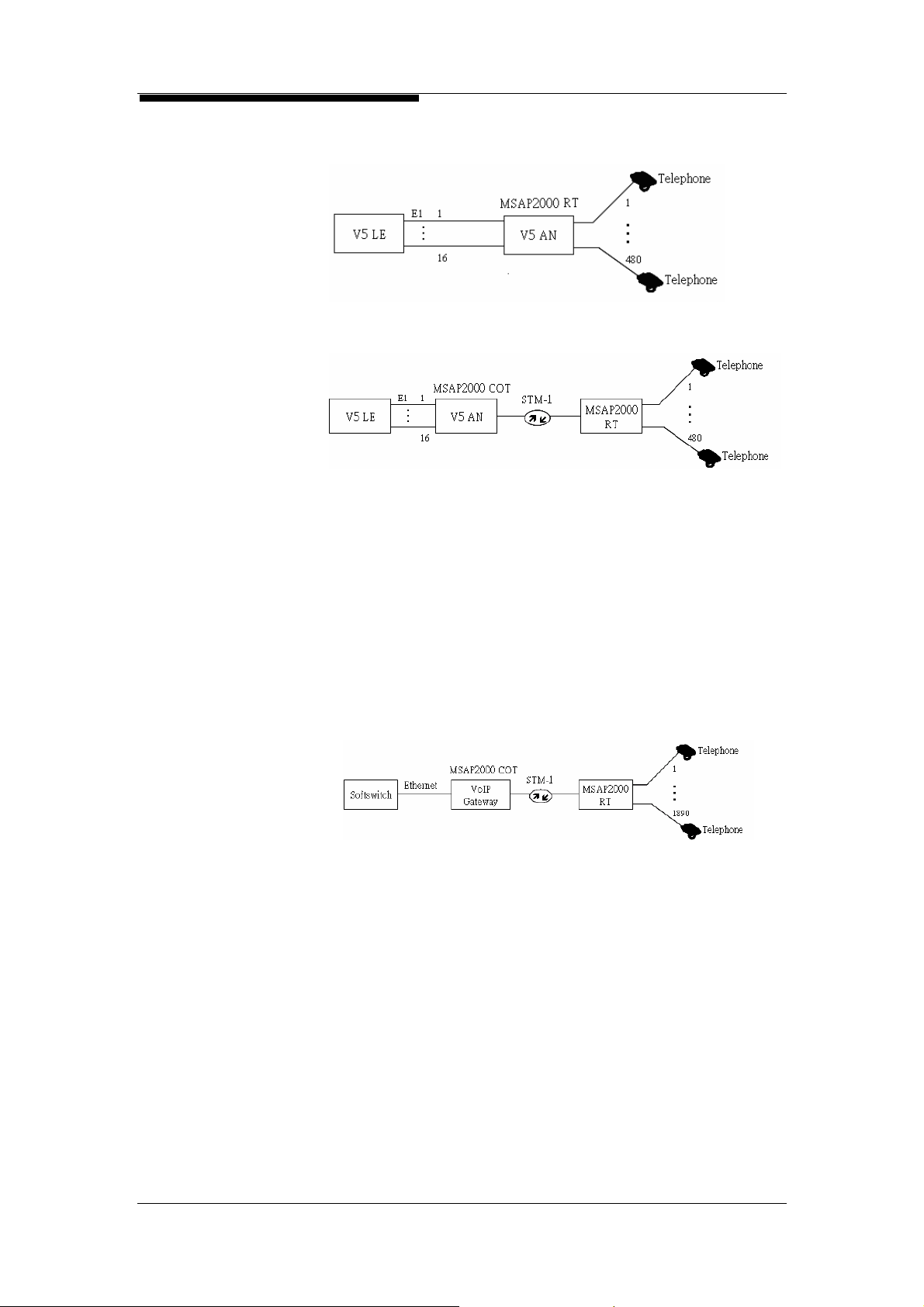
V5.1/V5.2
MSAP2000 supports V5.2 interfaces which comply with ITU-T
G.964, G.965 standards. One V5.2 interface can provide up to
16 E1 interfaces, which can support 480 lines of voice
subscribers under a 1:1 non-concentrated mode. V5.2
Protocols are concentrated on one V5P Module, in MSAP2000.
One V5P Module can simultaneously support 4 V5.2exchange
interfaces, meaning that one MSAP2000 System will provide
four sets of V5.2 interfaces. This amounts to a capacity of 63
E1 interfaces, and will support 7560 lines of voice services,
under 1:1 non-concentrated operation. V5P also supports 1:N
concentrated operation.
MSAP2000 Technical Manual V3.0 3-5
3. Application and Services
Single-end Configuration:
Dual-end Configuration:
Voice Over Packet
Service Providers face the common problem, of how voice
services can be integrated into their existing network
infrastructures. MSAP2000’s TDM over IP technology not only
complies with IETF PWE3 regulations, it can also use an
existing IP network to transmit subscriber voice signals to the
COT end, without having to invest in additional server
equipment. MSAP2000 also presents solutions for other VoIP
shortcomings, such as lack of testing functions. MSAP2000’s
MLTM Module provides copper wire testing for subscriber
loopback, which will help towards reducing maintenance cost.
MSAP2000 Technical Manual V3.0 3-6

3. Application and Services
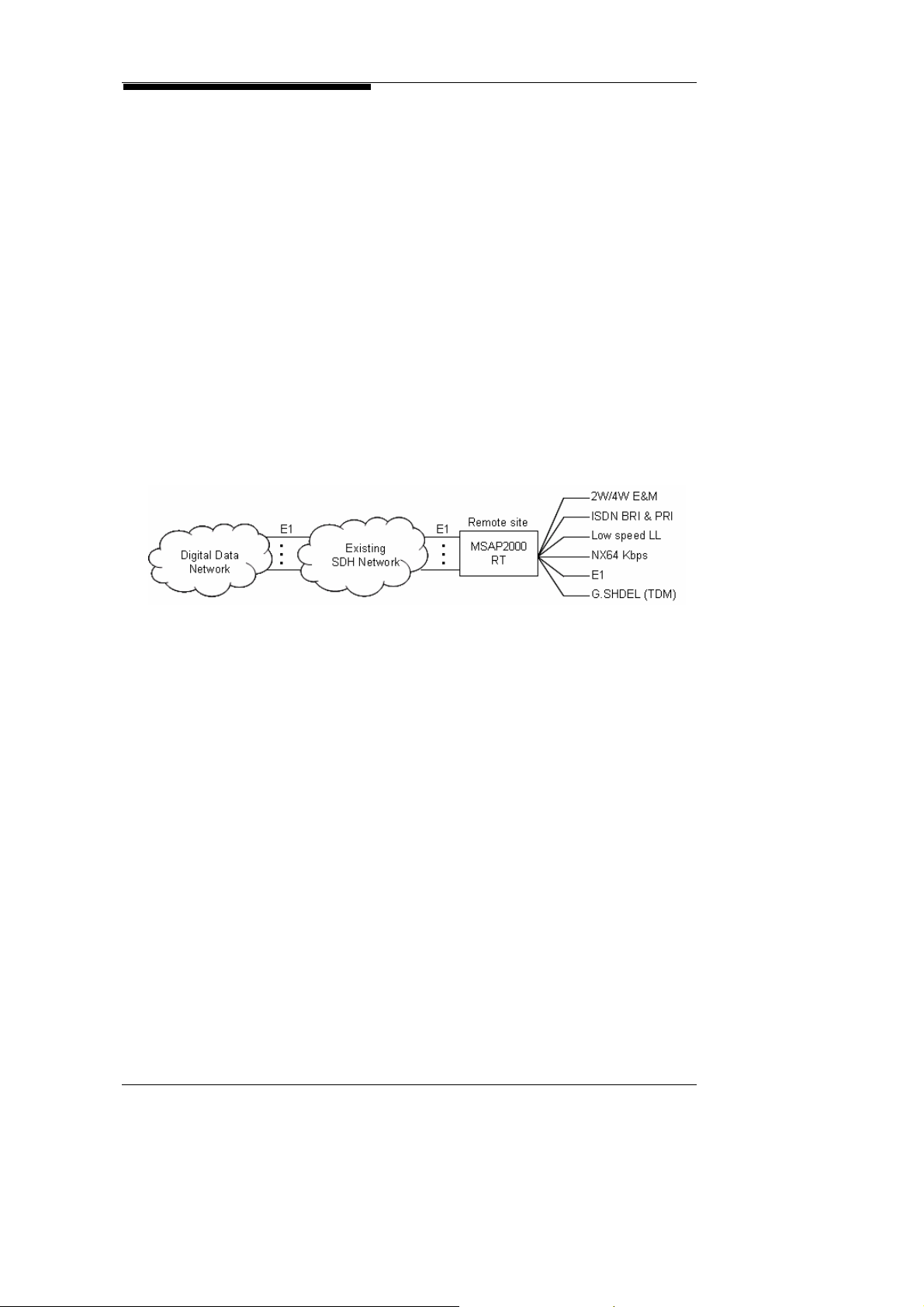
3.6. Application for Data Leased Line Services
In order to adhere to Quality of Service (QoS) Requirements,
most corporations still opt to select Data Leased Line services
over other services, for data maintenance.
MSAP2000 supports the following Leased Line Interfaces:
ISDN BRI/PRI
ITU-T V.35 Nx64 Kbps
ITU-T G.703 E1/ Fractional E1 (FE1)
G.SHDSL (TDM) with GSH-R Modem
Special Low Speed (<64 Kbps) Leased Line Interface (In
the future)
MSAP2000 Technical Manual V3.0 3-7

3. Application and Services
3.7. Application for DSL Services
SDH STIM-1 Trunk
xDSL over Optical Ethernet services possess the potential for
wide application, but its use has been limited, due to
geographical restrictions. MSAP2000 can offer various types
of xDSL services to remote areas, by using optic fiber-based
technologies to provide ADSL, ADSL2/ADSL2+ or G.SHDSL
interfaces. This can also be used to shorten subscriber loop
distances, which will in turn upgrade bandwidth service. Its
modular design can allow Service Providers to be upgraded
from a STM-1 155.52Mbps bandwidth, to Gigabit standards, at
their own pace.
MSAP2000’s AAM Module provides ADSL access services. A
subscriber packet is linked to the EoSM (Ethernet over SDH
Module) via a backplane bus. The EoSM encapsulates the
subscriber packet within a TDM format, using Ethernet over
SDH standards: ITU-T G.7041 GFP. The encapsulated packet
is then transmitted to the COT via a SDH trunking interface
(OIM), for connection to the next generation IP network. One
AAM Module can support 12 ADSL2/2+ subscribers, and one
shelf can accommodate up to 96 lines of ADSL. One
MSAP2000 shelf can support up to a maximum of 576 ADSL
subscriber interfaces.
MSAP2000 Technical Manual V3.0 3-8

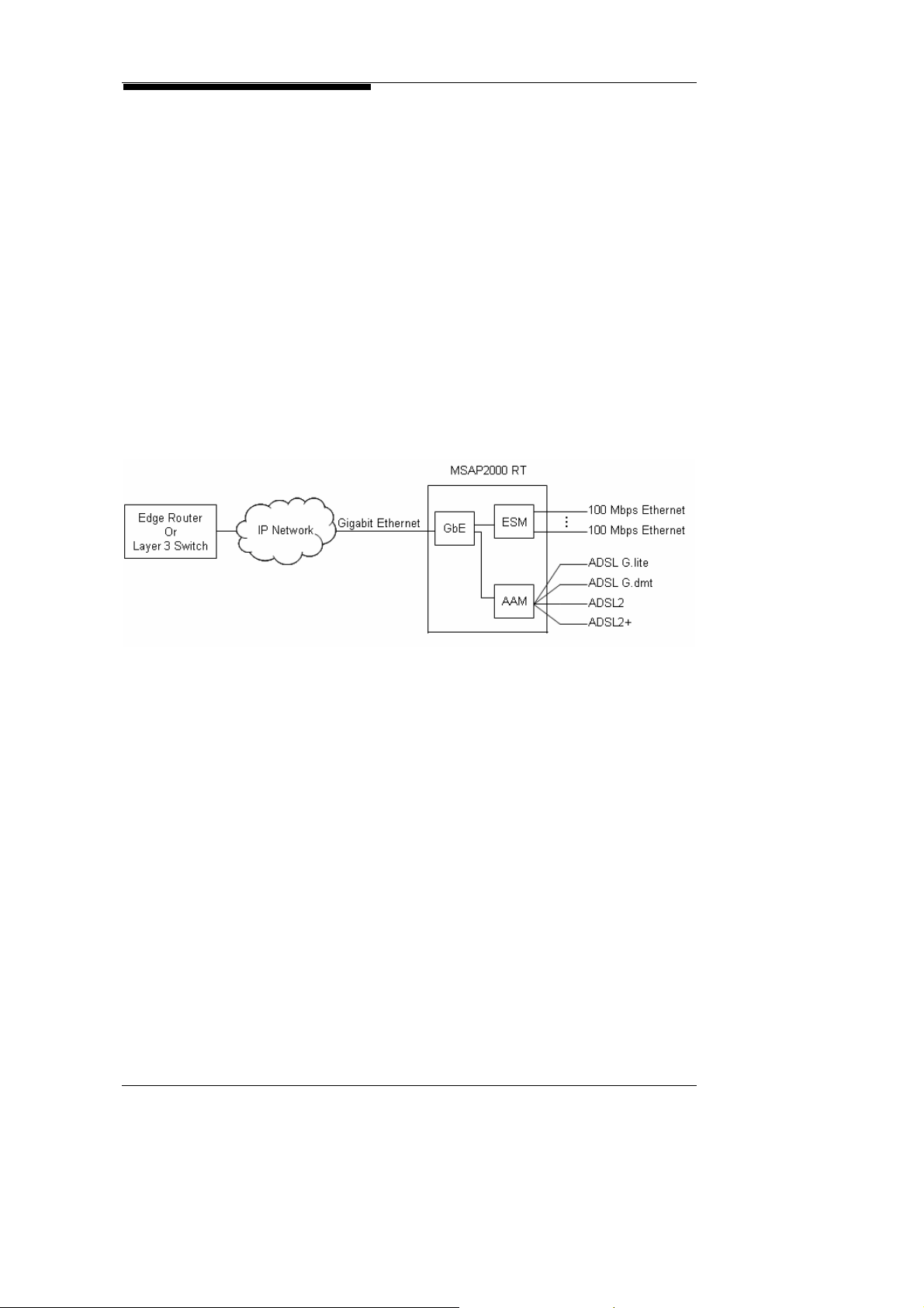
3. Application and Services
Optical Gigabit
Ethernet
MSAP2000 supports Gigabit Ethernet (GbE) optic transmission.
The AAM Module can directly connect the packet to the GbE via
an IP backplane bus; it is then directly connected to the Router,
or the Layer 3 Switch of the telecommunications server room,
via optic fiber transmission.
3.8. Ethernet over SDH Services
Because SDH was formerly widely used as a basis for network
construction, there is a surplus of unused SDH bandwidths.
MSAP2000 transmits Ethernet packets by SDH, using ITU-T
G.7041 transmission modes. This solution can allow network
Service Providers to utilize existing network bases, for Ethernet
service provision.
As shown in the following diagram, MSAP2000 can provide
each individual subscriber with simultaneous phone and
broadband access services.
MSAP2000 Technical Manual V3.0 3-9

3. Application and Services
3.9. Microwave radio application
STM-1 electrical
interface
PSTN
IP
Network
DDN
Ethernet
FE/GE
QE1M
CEoSM
E1 interface
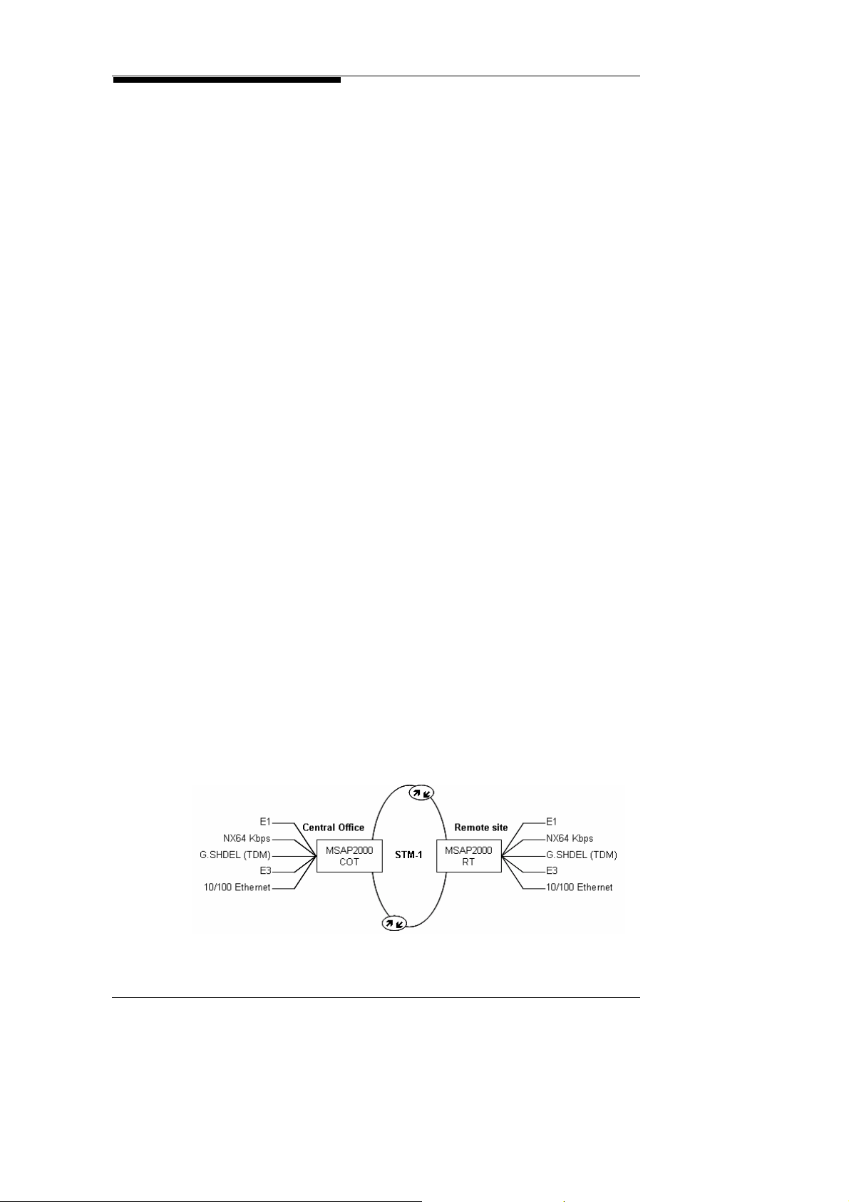
MSAP2000 supports microwave radio as transport media for areas
geographically not suitable or impossible for copper or fibe r opti c cabl es
deployment. SM1 modules provides electrical interface to connect to
STM-1 microwave radio for urgent deployment of voice, data leased line
and internet access service.
V5P
FXS
SM1
SM1
REoSM
AAM
QE1MQE1M
For areas with less demand in bandwidth capacity, MSAP2000 supports
E1 microwave radio links voice for PSTN network and narrowband data
leased line for GSM network. QE1C also supports up to 360 DS0 with
single E1 link. Multiple E1 links are also supported if multiple microwave
radio links are available.
1
12
Data
service
PSTN
GSM
Network
Ethernet
FE/GE
V5P
QE1M
FXS
QE1C QE1C
ETHETH
MSAP2000 Technical Manual V3.0 3-10

3. Application and Services
THIS PAGE IS LEFT BLANK
MSAP2000 Technical Manual V3.0 3-11

4. System Components
Table of Contents
4. System Components .............................................................................................................4-1
4.1. Overview................................................................................................................4-1
4.2. Terminal.................................................................................................................4-2
4.3. Shelf.......................................................................................................................4-3
4.4. Common Control Modules..... .... .... .... .... ........ .... .... .... .... .... ... .... .... ..... ........ .... .... ... .4-6
4.5. Trunk Interface Module..........................................................................................4-8
4.6. COT Network Interface Module.............................................................................4-9
4.7. Subscriber Interface Module................................................................................4-12
4.8. Subscriber End Facilities.....................................................................................4-15
4.9. Indoor Rack ........................................... ........ .... .... .... .... .... .... .... ....... .... .... .... .... ...4-16
4.10. Outdoor Cabinet..................................................................................................4-17
MSAP2000 Technical Manual V3.0 i

4. System Components
THIS PAGE IS LEFT BLANK
MSAP2000 Technical Manual V3.0 ii

4. System Components
4. System Components
4.1. Overview
MSAP is a next generation Broadband Loop Carrier (BLC),
composed of a Central Office Terminal (COT) and a Remote
Terminal (RT). The COT is installed in the Central Exchange
Station, and uses transmission media such as STM-1/4 optic
fibers, E1 circuits, or microwave, to connect to the RT installed in
metropolitan, suburban or remote areas. The subscriber may
also connect to the RT via GSH-R devices.
MSAP2000 uses advanced semiconductor devices and
microprocessors to enhance circuit density, and to reduce space
usage, making MSAP2000 ideal for installation in compact
metropolitan exchange stations, or in constricted outdoor cabinets.
MSAP2000 provides the following modular interfaces:
Voice Service Modules: FXS/FXO, Payphone, 2W/4W E&M,
ISDN BRI/PRI
Digital Leased Lines: NX64 Kbps, E1, G.SHDSL
DSL Services: ADSL G.dmt, G.lite, ADSL2/2+
Ethernet Module: ETH, ESM
IDLC Module: V5P(V5.1/V5.2 Interface)
Ethernet over SDH Module: EoSM
Trunk Interface Module: OIM(STM-1), QE1M(Quad E1),
GbE(Gigabit Ethernet)
VoIP Module: PVM
Common Modules: Power supply modules (RtPSM, CoPSM),
Main Processing Modules(MPM), Expansion Modules(ELM,
EPM)
Testing Module: Metallic Line Testing Module (MLTM)
All of MSAP200 0 ’s m o du les ar e de s i gn ed as plug-in cards with
ejectors for convenient removal. The modules are built-in into
the System, and can be hot-plugged and unplugged, without
interference to the System’s operation.
MSAP2000 Technical Manual V3.0 4-1

4. System Components
4.2. Terminal
Central Office
Terminal (COT)
Remote Terminal
(RT)
Node
Each network has only one Central Office Terminal (COT), and all
data from the various remote terminals will be converged onto this
COT. The various interfaces within the COT will then process
the received data, and transmit it to the corresponding devic es.
MSAP2000’s Timeslot Division and Cross-Connect functions will
not only efficiently utilize bandwidth, but will also reduce the need
for excess access ports. One MSAP2000 COT provides 1890
lines of 1:1 voice services, and a total bandwidth of 1 Gbps can be
achieved with use of GbE.
Each MSAP2000 supports up to 16 RTs; each RT can be installed
in proximity to the subscriber, to cut down on loop distance.
MSAP2000’s capacity can be expanded by shelf-stack ing, and its
COT/RT can provided a range of system capacities from 16, 30,
60, 120, 240, 360, 480, 600, 720, 960, to 1890 lines. The
maximum quantity of lines supported by the RT will only equal, or
be less than the quantity of lines supported by the COT. RTs
may be either housed in cabinets, or installed upon 19-inch,
23-inch, or any size rack which conform to ETSI ETR 300 119
standards. Based on different subscriber requirements, rack
placement can be ground-based, hung, or wall-mounted.
The MSAP2000 use the common shelf and each shelf can be
configured as the role of COT or RT by modifying the DIP switch
located at the rear side of the backplane. Detail setting can be
found on section 12.2.
When using the OptiCore Network Management System to
monitor MSAP2000 terminals, each terminal is termed a “node”
within the network topology.
MSAP2000 Technical Manual V3.0 4-2

4. System Components
4.3. Shelf
Main
Shelf
Extension Shelf
MSAP2000 can be encased within any 19 or 23-inch rack, or any
standard rack which conforms to ETSI ETR 300 119 standa rds. The
rack is composed of a backplane and an external case. All wires within
the MSAP2000 shelf are ready-to-use, apart from trunking wires and
subscriber lines, which will have to be deployed by the subscribers
themselves. Dus t covers will be provided for the unused slots within
the shelf. All of the subscribers’ copper lines are connected via wire
wrapping. Three connection ports: RS-232, Ethernet and RJ-11 are
located in the lower right hand corner of the shelf. These ports can
allow subscribers to connect to the LCT interface, the NMS interface,
and to Payphones/Order Wires.
Each MSAP2000 terminal includes a Main Shelf. Each Main Shelf is
composed of a shelf/chassis, power modules, main control modules,
trunking modules, and subscriber modules. The dip-switch on the
backplane of the main shelf will determine the function of this shelf,
within the overall network. Setup details will be listed in the
“Installation Procedure” section of this Manual.
Extension shelves are only used when the capacity of the main shelf is
insufficient. When adding an extension shelf, both the main shelf and
the extension shelf will need to have extension control modules
installed; the modules on both ends will then be linked by multi-module
optic fibers. The extension shelf itself is complete with its own shelf
case, power modules, extension control modules, and subscriber
modules. Within the Network Management System, the extension
shelf will be shown as a node within the network topology. For
example, if the main shelf is shown as 1, extension shelves can be
shown as any number from 2~8.
MSAP2000 Technical Manual V3.0 4-3

4. System Components
Slot
MSAP2000’s common shelf is as shown in Figure 4-A. Each shelf
includes 22 slots, and the slots are numbered as 1, 2, 3, ….19, 22. Slot
functions are as shown below (details can be found in Chapter 5 Slot
Chart):
Slots 21 & 22: for Power Supply Modules (PSM).
Slots 19 & 20: for MPM and EPM only.
Slot 18: GbE and REoSM
Slots 1~16: Modules that requires wiring at backplane, which include:
FXS, FXO, FXS-P, FXO-P, 2W/4W E&M, LULT/LUNT, QE1M, GSH,
V5P, N64M, V24M, ESM, AAM, MLTM.
Slots 2, 4, 6, 8, 10, 12, 14 & 16: AAM when using with REoSM.
Slots 1~18: CEoSM, OIM, ELM, PVM
Port
Channel
There is only one MSAP2000 chassis. The same chassis can serve as a
terminal shelf, remote shelf, or an extension shelf, simply by changing
the Hardware Address on the backplane PCB.
When a slot module is not based at 64Kbps (DS0) , the inter face access
is called a port. For example, MSAP2000’s QE1M has 4 physical ports,
so its assignation numbers are from 1~4.
When a slot module is based at 64kbps (DS0), the interface access can
be further divided by the designation of port and cha nnel. For example,
MSAP2000’s QE1M is a subscriber module; each interface will provide
30 time slots, so the effective assignation numbers are port-1~port-30.
For POTS, since there is only one channel in each port, the channel
designation is omitted. So for each FXS-P providing 8 voice circuits, the
effective assignation numbers are 1~8. Each FXS/FXO provides 16
lines of voice circuits, so that the effective assignation numbers are
1~16. Each E&M provides 4 lines of voice services, so the effective
assignation numbers ar e 1~4. When a FXO is inserted into the fifth slot
of a COT main shelf, its tenth port is displayed as COT-1-5-10.
MSAP2000 Technical Manual V3.0 4-4
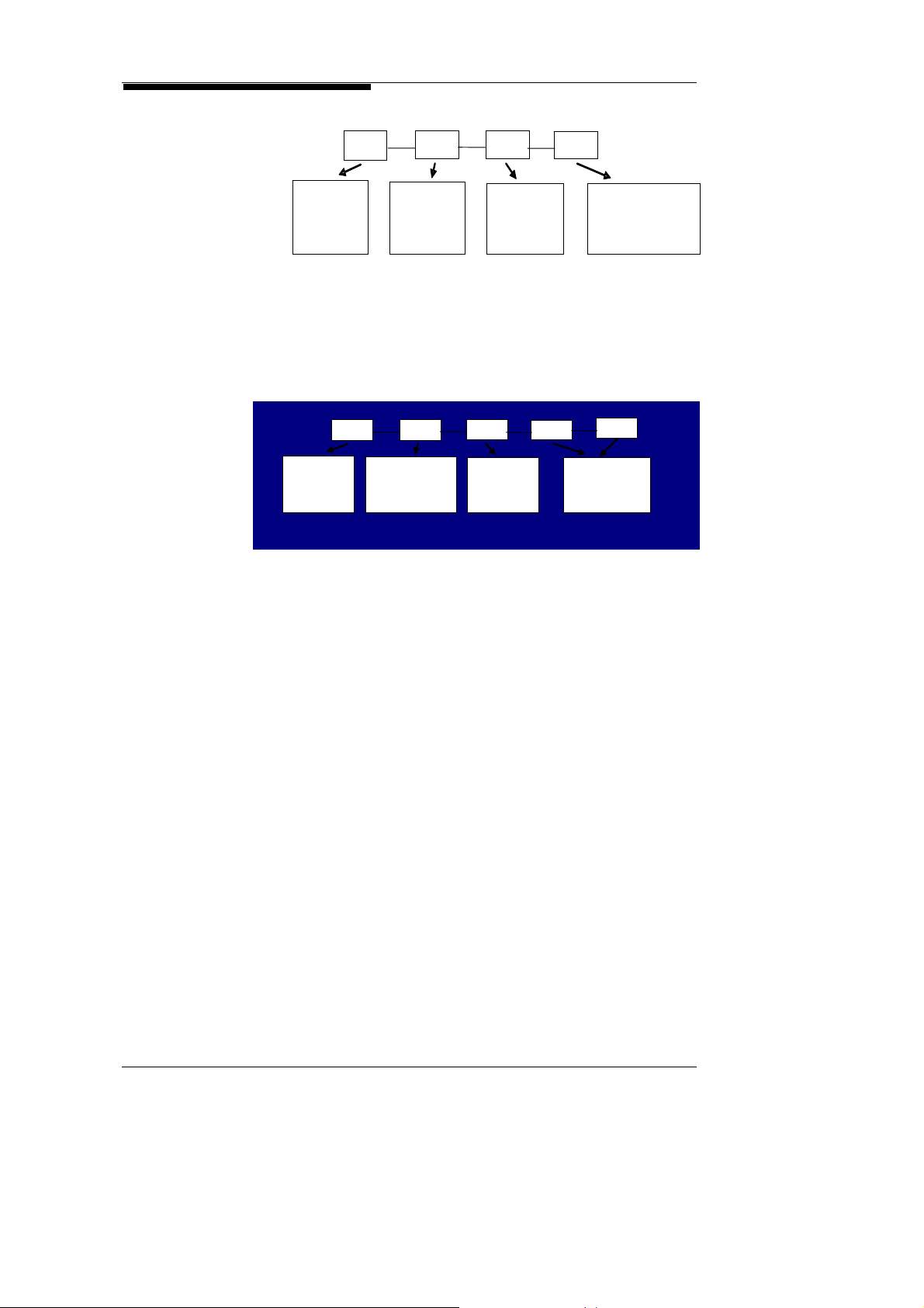
4. System Components
COT
1
5
4
NODE=
COT
When a QE1M is plugged into the 8
assigned to be used as a subscriber module, the 20
port is shown as RT5-2-8-4-20. (Note: The first extension shelf is
SHELF=2)
NODE=
RT5
RT5
SHELF=
SHELF=
Extension Shelf 1
SLOT= 5
port=4
th
slot of RT5’s extension shelf, and
2
8
SLOT= 8
th
channel in its 4th
4
PORT= 4
channel=20
20
MSAP2000 Technical Manual V3.0 4-5

4. System Components
4.4. Common Control Modules
CoPSM
RtPSM
MPM
ELM
MSAP2000’s Common Control Modules form the basis for the
MSAP2000 System Platform. Common Con trol Modul es include
Power Supply Modules (RtPSM, CoPSM), Main Processing
Modules (MPM), Expansion Link Modules (ELM), Expansion
Processing Modules (EPM), and Metallic Line Testing Modules
(MLTM).
Module Slot No. Function Note
CoPSM 21, 22 Power supply
RtPSM 21, 22 Power supply When RINGER is
needed.
MPM 19, 20 Main processing
ELM 1~ 18 Connection to
extension shelf
EPM 19, 20 Connection to Main
shelf
MLTM 1 ~ 16 External Subscriber
line testing
V5P 1 ~ 18 V5.2 Protocol
The COT Power Supply Module (CoPSM) on the COT end
collects -36 to -72 DC power supplied by the Exchange Station,
and converts it into various types of DC voltage for use by
MSAP2000’s modules. Each COT will need at least one
CoPSM; a second CoPSM may be installed as a precaution, for
standby support.
The RT Power Supply Module (RtPSM) receives -36 to -72 DC
power, and converts it into various types of DC/AC voltages for
use by MSAP2000’s modules. Each RT shelf will need at least
one RtPSM; a second RtPSM may be installed as a precaution,
for standby support. RtPSM differs from CoPSM in the RINGER
generation for the phone services. A Rectifier can be added to
the RtPSM, so that it can receive 90-240 volts of AC power.
Both the COT and RT include a Main Processing Module (MPM),
which is used to provide a Local Craft Interface (LCI) and SNMP
Agent, to perform management functions such as system startup,
setup, maintenance, circuit performance analysis, testing, and
fault analysis. The MPM uses a non-volatile memory device to
save System operation data. The MPM also provides a Local
Craft Terminal Interface, which can be connected via the RJ9 port,
and Order Wire functions, which can be connected through the
RS-232 port on the lower right corner of the shelf panel.
The Expansion Link Module (ELM) is located within the Main
Shelf, and its function is to provide connection to the Extension
processing
MSAP2000 Technical Manual V3.0 4-6

4. System Components
shelf’s EPM. The ELM’s Digital Cr oss Connect function can link
any subscriber channel within the System to the extension shelf.
When there are not enough slots in the main shelf, the ELM can
be used as a system extension shelf.
EPM
MLTM
V5P
The Expansion Processing Module’s (EPM) function is to provide
connection to the ELM within the Main Shelf, an d it c an b e placed
within slots 19 or 20 of the extension shelf. The EPM’s Digital
Cross Connect function will transmit the extension shelf data over
to the Main shelf.
The Metallic Line Testing Module (MLTM) connects the subscriber
to the Helpdesk via public Network, or Digital Leased Lines. The
MLTM first receives commands and messages sent from the
Helpdesk, then test the subscriber line within the carrier system,
and send the test results back to the Helpdesk.
V5P is a V5.2 Protocol Processing Module, which supports ITU-T
G.964, G.965 standards.
MSAP2000 Technical Manual V3.0 4-7

4. System Components
4.5. Trunk Interface Module
OIM/SM1/SM4
GSH
QE1M
MSAP2000’s Trunk Interface Module uses copper wires, optic
fibers, or wireless transmission, to connect the COT and RT.
Based on usage of different technologies, the Trunk Interface can
be divided into two types: TDM and IP. QE1M an d OIM (STM-1
Optical Interface) are TDM technology based, while GbE (Gigabit
Ethernet) is IP technology based. The Trunk Interface Module is
installed within the Main shelf, and multiple trunk interfaces can be
installed, based on different application purposes. QE1M and
OIM both support 1+1 Protection Switch mechanisms; the
System’s backplane wiring setup will not be affected by different
trunking methods.
Module Slot No. Line Capacities Note
OIM/SM1 1 ~ 18 1890 DS0
SM4 1 ~ 16 7560 DS0
QE1M 1 ~ 16 120 DS0 1+1
GSH 1 ~ 16 36 DS0 (*depends on
loop quality)
QEToP 1 ~ 16 120 DS0 1+1
GbE 18 1 Gbps Supports 756
OIM/SM1 is a STM-1 optic interface module and SM4 is a STM-4
optical interface module, which conforms to ITU-T G.957
standards. With OIM/SM1/SM4, MSAP2000 can form various
network topologies, such as Point-to-Point, Star, Linear, Tree and
Branch, and Ring. Total number of OIM/SM1/SM4 modules can
be up to 10 when used in star configuration on one shelf with
redundancy in consideration. OIM/SM1/SM4 provides automatic
protection switch functions, such as 1+1 Protection Switching for
Star topologies, and Protection for Ring topologies.
OIM/SM1/SM4 also supports enforced protection switching
mechanisms. The switch time is under 50ms, and ongoing
services will not be interrupted during switching.
When GSH is provisioned as the trunk interface for the DSL
pair-gain application, the M-bonding for the capacities expansion
is also provided. The remote power feeding option for 120~ 180V
is also provided and the concentration to allow more number of
subscribers. In low-density usage, other than MSAP2000 system
shelf, a small form factor shelf to allow poll or wall mounted to
work with GSH trunk.
QE1M is a MSAP2000 trunk interface, which connects the COT
and RT by copper wires. QE1M conforms to 2,048 Kbit/s ITU-T
G.703/G.704/G.706 interface standards and can be connected to
external microwave radio equipment where optic fibers are yet to
deployed or impossible to lay. The total number of QE1M for a
single shelf can be up to 16 for both trun k and service interface.
1+1, & Ring
Protection
Switching
Protection
M-Bonding.
Protection
ADSL
MSAP2000 Technical Manual V3.0 4-8

4. System Components
QE1M provides performance monitoring functions, and it will
generate Near and Far end performance parameters for the data it
collects, such as data for Error Second (ES), Severely Error
Second (SES), and Unavailable Second (US). The history data
will record the current ES, SES and UAS information, the ES, SES
and UAS information for the past 8 hours, and also the ES, SES
and UAS information for the past 7 days.
GbE
MSAP2000 provides one Gigabit Ethernet optic trunk interface
(GbE). Besides supporting various Protocols such as IEEE
802.3z, 802.1d, 802.1p, 802.1q, the GbE Module also collects
status, fault, alarms and performance information. The GbE
Module can connect the RT to Ethernet devices directly or serve
as the trunk interface between COT and RT when circuit
emulation for E1 is required, or it can serve as a trunk interface to
connect the COT and RT, to provide broadband services.
4.6. COT Network Interface Module
FXO
MSAP2000’s COT provides interfaces for PSTN, Digital Data
Networks, and IP Networks. Its modular de sign allows network
planning personnel to select the quantity and type of network
modules, based on their own individual requirements.
MSAP2000 can provide connection to PSTN interfaces via analog
2W interfaces (FXO) or V5.2 interfaces. Linkage to a Digital Data
Network is made via 2Mbps E1, and it also has a GbE interface for
connection to IP networks.
PSTN Interfaces
y FXO (POTS)
y FXO-P (Payphone)
y LUNT (ISDN BRI)
y E1 (V5.2)
Analog Leased Line Network Interfaces
y 2W E&M
y 4W E&M
Digital Data Network (DDN) Interfaces
y QE1M (Synchronous/Asynchronous E1, Fractional E1, ISDN
PRI)
y N64M (Nx64 Kbps with ITU-T V.35 Interface)
Asynchronous Data network Interfaces
y V24M (for computer asynchronous network like RS-232)
IP Network Interfaces
y ETH (Fast Ethernet over TDM, using HDLC bit
encapsulation)
y EoSM (Fast Ethernet over SDH, using GFP or X.85/86)
y GbE (Gigabit Ethernet)
Next Generation Network Interfaces for Soft-switch
y PVM (Packet Voice Module integrates VoIP Gateway with
SIP, H.248 and MGCP)
The FXO Module is normally installed within the COT Shelf, and it
provides 16 lines of 2-wire analog voice interfaces for connection
to PSTN Exchange Stations. The functions of FX O include Dial
Ring Detection, Busy tone detection, ringing tone detection, Loop
MSAP2000 Technical Manual V3.0 4-9

4. System Components
Current initiation, Voice Signaling transfer, and Tip-Ring Reversal
(Polarity Guard) for subscribers’ line. The FXO in the COT will
be associated with the FXS installed in the RT, to provide voice,
FAX, and modem dial-up services.
FXO-P
2W/4W E&M
LUNT
QE1M
ETH
EoSM
The FXO-P Module is installed within the COT Shelf, and provides
8 lines of 2-wire analog Payphone interfaces. FXO-P
automatically detects the charging signals sent from the Exchange
Station, and generates a corresponding charging signal on the RT
end, to initiate the Payphone’s charging mechanism. FXO-P
supports 12 KHz and 16 KHz charging signals (software
configurable) and battery reversal charging signal.
The 2W/4W E&M Module (2W/4W Ear and Mouth Module)
provides 4 lines of 2-Wire or 4-Wire subscriber services. The dip
switch on the module can be used determine either a 2-wire or
4-wire setting. Both 2W and 4W interfaces conform to ITU-T
G.712 standards. E&M supports circuit status detection as well
as signaling, and its voice frequency gain is configurable by
software. E&M supports Type V and Transmit Only (TO) modes.
Like NT1, LUNT works as a “Slave” Digital Subscriber Line
Transmitter. It is installed in the COT and connected to the
Exchange LT. LUNT receives 2B1Q DSL signals, and
multiplexes the signals into the 64 kbit/s timeslot chann el of the
trunk interface. Each ISDN Module will occupy 3 64kbit/s trunk
interface timeslots. LUNT conforms to ITU-T G.797, ETSI ETR
080, and ANSI T1.601-1992 standards.
QE1M provides 4 ITU-T G.703 E1 interfaces. QE1M can be
setup as the trunk interface module or the subscriber/network
testing module, via the LCT (Local Craft Terminal) or NMS.
QE1M can serve as the E1 interface for V5.2 Exchange Switch,
and it can also function as a Leased Line Network interface. As a
Leased Line Network interface, QE1M’s Grooming functions can
cross connect signals from the RT’s 2W/4W or E1 interface, at a
64 Kbit/s timeslot basis, to any E1 interface on the COT Network,
to form E1 signals. The same can be done for signals from
G.SHDSL GSH-R’s V.35 and E1 interface.
The ETH (Ethernet Interface Module) provides 10 Base-T and 100
Base-TX Auto-Negotiation Interfaces. ETH conforms to IEEE
802.3 Ethernet and IEEE 802.3u Fast Ethernet standard
regulations, and supports Full Duplex and Half Duplex
transmission. ETH p rovides Rate Limiting functions, and it can
support a transmission distance of up to 100 meters with Cat-5
UTP 10 copper cables. With a RJ-45 connector, its frequency
width can be configured to start at 1 Mbit/s, and increased up to 16
Mbit/s, at 1 Mbit/s per step. The final error rate is less than 10 %.
The technologies used in ETH is the HDLC bit encapsulation and
ETH must be with another ETH or GSH + GSH-R (ETH in terface)
to provide the leased line quality to the enterprise users.
There are two kinds of the EoSM Modules namely the CEoSM and
REoSM. CEoSM and REoSM provide Ethernet over SDH
functions. They conforms to ITU-T G.7041 Generic Framing
Procedure (GFP), and also supports IEEE 802.3u 10 /100
Ethernet interfaces. One port is provided for one uplink in a pair of
MSAP2000 Technical Manual V3.0 4-10

4. System Components
EoSM modules. Each shelf can have as many as 16 CEoSM to
be used as uplink to Edge router for DSL leased line service.
The REoSM differs from CEoSM in the access of the Ethernet bus
of the MSAP2000 backplane. REoSM can work with AAM or ESM
to provide more than one Ethernet interface to the subscribers.
MSAP2000 Technical Manual V3.0 4-11

4. System Components
4.7. Subscriber Interface Module
FXS
FXS-P
MSAP2000 is a broadband network access platform, with
integrated functions that can satisfy all customer needs. Its
subscriber interfaces include:
Analog Voice Interfaces: FXS (POT), FXS-P (Payphones), 2W/4W
E&M.
Digital Leased Line Interfaces: ISDN BRA/PRA, Nx64 Kbps, E1,
SDSL and G.SHDSL.
xDSL Interfaces: ADSL G.LITE, G.DMT, ADSL2/2+, and
G.SHDSL
Ethernet Interfaces: 10/100 Ethernet.
Analog Voice Interfaces:
y FXS (POTS)
y FXS-P (Payphones)
ISDN Interfaces
y LUNT (ISDN BRI)
y QE1M (ISDN PRI)
Analog Leased Line Interfaces
y 2W E&M
y 4W E&M
Digital Data Network Interfaces
y QE1M (ITU-G G.703 Full E1、Fractional E1、Asynchronous
E1)
y N64M (Nx64 Kbps with ITU-T V.35 Interface)
y GSH (HDSL, G.SHDSL with Nx64 Kbps N=1~36)
IP Network Interfaces
y ETH (Ethernet over TDM)
y ESM (8-Port Ethernet Switch)
xDSL Interfaces
y AAM (ADSL G.dmt、G.Lite、ADSL2、ADSL2+
High Speed Data Interfaces
y STM -1 Electrical Interface (In SM1)
FXS provides 16 POTS interfaces. It supports DP (Dial Pulse)
and DTMF (Dual Tone Multiple Frequency) dialing modes, and it
adapts ITU-T G.711 standard A-law Companding coding rules and
CAS (Channel Associated Signaling). Its Link Performance
conforms to ITU-T G.712 standards as well as Chunghwa
Telecom’s ME 2401-4 Specifications. With no concentration or
compression, the maximum number of subscriber ports in one
shelf is 256. The maximum number of subscriber lines in one
system, without having to consider concentration or compression
is 1,890, while the number can increase to 7,560 with
concentration or compression.
The FXS-P Module is usually installed within the RT Shelf, and
MSAP2000 Technical Manual V3.0 4-12

4. System Components
provides 8 lines of 2-Wire Analog Payphone Interfaces. FXS-P
generates 12 KHz or 16 KHz charge signals (software
configurable) on the RT end, to initiate the Payphones’ charging
functions. With no concentration or compression, the maximum
number of subscriber ports in one shelf is 128. Th e maximum
number of subscriber lines in one system, without having to
consider concentration or compression is 1024.
2W/4W E&M
LULT
N64M
QE1M
GSH
The 2W/4W E&M Module (2W/4W Ear and Mouth Module)
provides 4 lines of 2-Wire or 4-Wire subscriber line services. The
dip switch on the module can be used determine whether a 2-wire
or 4-wire setting is to be used. Both 2W and 4W interfaces
conform to ITU-T G.712 standards. E&M supports circuit status
detection as well as signaling, and its voice frequency gain is
configurable by software. E&M supports Type V and Transmit
Only (TO) modes.
The LULT Module provides 4 lines of 2B1Q ISDN basic rate
transmission. The digital subscriber loop signals in this module
consist of dual course 144kbit/s 2B+D subscriber data, plus
4kbit/s of operation bits, and a 12 kbit/s synchronous bit rate
frame. Like the ISDN Exchange LT, LULT works as a “Master”
Digital Subscriber Line transmitter. It is installed in the RT of
MSAP2000, and its bit frame architecture conforms to ITU-T
G.797, ETSI ETR080, ANDSI T1.601-1992 specifications.
N64M provides a Nx64 Kbps Digital Transmission Interface.
N64M uses a V.35 standard port to conduct Digital Leased Line
services for Nx64 Kbps (N=1~31). Subscriber transmission
bandwidth can be configured via the LCT.
QE1M provides 4 ITU-T G.703 E1 interfaces. It can be assigned
to work as a trunk interface module, or a subscrib er test/network
test module, via LCT of NMS settings. As a subscriber interface
module installed on the RT side, it can be software configured to
provide Fractional E1 functions. Its bandwidth can be set to 64
Kbit/s timeslot, and cross-connected to any E1 interface on the
COT end, to form/groom E1 signals.
GSH provides 1 G.SHDSL (TDM-based) leased digital interface.
It is installed within the RT, and can work with G.SHDSL Modem
GSH-R to support ITU-T V.35, G.703 E1, and Ethernet interfaces.
A single System can provide up to 63 lines of GSH interfaces.
GSH supports ITU-T G.99 1. 2 , G.994.1, and Chunghwa Telecom’s
MD6230-1 specifications. GSH supports Nx64 Frequency Width
adjustment. The signals from GSH-R’s subscriber V.35 and E1
interface can be cross-connected to any E1 interface on the COT
end, to form/groom E1 signals. Maximum number of G.SHDSL
line per shelf is 16, while the maximum number of G.SHDSL line
per system is 128.
MSAP2000 Technical Manual V3.0 4-13

4. System Components
ETH
ESM
AAM
The ETH (Ethernet Interface) Module provides 10 Base-T and 100
Base-T Auto-Negotiation Interfaces. ETH conforms to IEEE
802.3 Ethernet and IEEE 802.3u Fast Ethernet standard
regulations, and supports Full Duplex and Half Duplex
transmission. ETH p rovides Rate Limiting functions, and it can
support a transmission distance of up to 100 meters with Cat-5
UTP 10 copper cables. With a RJ-45 connector, its frequency
width can be configured to start at 1 Mbit/s, and increased up to 16
Mbit/s, at 1 Mbit/s per step. The final error rate is less than 10%.
ESM is an 8 port LAN switch Module; each module provides 8
IEEE 802.3 10/100 Auto-Negotiation Ethernet interfaces. ESM
supports IEEE802.1d STP, 802.1p, Port-based & tag-based
VLAN, and Static MAC address filtering.
The ADSL Access Module (AAM) provides 12 lines of ADSL
subscriber interfaces, and supports ITU-T G.992.1, G.992.2, ANSI
T1.413 issue 2, ADSL2 (G.992.3, G.992.4), ADSL2+(G.992.5),
ITU-T G.994.1 specifications. AAM is IP-based, and it s upports
802.3/3u/3x 100 Mbps Ethernet frequency width. AAM provides
VLAN, GVRP, IGMP snooping, PPPoE and DHCP functions.
Maximum number of ADSL subscriber lines per shelf is 96 while
maximum number of ADSL subscriber lines per shelf is 576.
MSAP2000 Technical Manual V3.0 4-14

4. System Components
4.8. Subscriber End Facilities
GSHDSL Modem
(GSH-R)
E1 Interface
V.35 Interface
Ethernet Interface
The GSH Module (G.SHDSL Line Card) is installed in MSAP2000
RT, and connected to the Client end facility (G.SHDSL mo dem)
via 2-wire copper lines. The GSH Module provides three types of
Digital Leased Line Interfaces:
(1) ITU-T G.703 E1 Interface
(2) ITU-T V.35 Interface
(3) 10/100 Base-TX Ethernet Interface
Complies with ITU-T G.703/G.704/G.706.
Please refer to Chapter 11 of this Manual for information on
technological details and interface parameters.
Supports N×64 Kbit/s subscriber data frequency. N=1~31.
Provides 10Base-T and 100Base-TX Auto-Negotiation
Interfaces.
Complies with IEEE 802.3 Ethernet and IEEE 802.3u Fast
Ethernet standard regulations, and supports F ull Duplex and
Half Duplex transmission. With Cat-5 UTP 10 copper cables,
its transmission distance can reach up to 100 meters.
Provides Rate Limiting func tions for receiving and transmitting
data. The frequency range can be set to anywhere from 192
Kbit/s to 2048 Kbit/s (adjusted at 64 Kbit/s per step). The
final error rate is less than 10%.
Uses a RJ-45 Connector
ADSL Modem
MSAP2000 Technical Manual V3.0 4-15
The AAM (ADSL Access Modem) Module is installed in the
MSAP2000 RT. It provides a subscriber bandwidth access
interface by connecting to the subscriber’s ATU-R (ADSL modem)
via 2-wire copper lines.

4. System Components
4.9. Indoor Rack
The MSAP2000 chassis can be installed upon any 19 or 23-inch
rack, or on any rack that complies with ETSI ETR 300 119
standards. A MSAP2000 shelf is 5U in height; the installed COT
shelf includes a Fuse Alarm Panel installed on top, and a
ventilation fan set. The MSAP2000 RT shelf also requires a
Fuse Alarm Panel installed on top; an Optic Fiber Distribution
Frame and a Digital Dist ributio n Frame c an be ad ded if necessary.
The main shelf is installed below the Digital Distribution Frame,
and comes with a ventilation fan set. An extension shelf and
additional fan set can be installed if required, but MSAP2000’s
extension shelf does not required fans, under normal
circumstances.
MSAP2000 Technical Manual V3.0 4-16

4. System Components
4.10. Outdoor Cabinet
Functions and
Accessories
The MSAP2000 RT can also be installed inside a cabinet. The
cabinet can be ground-based, hung, or wall-mounted, according to
different cabinet sizes and installation requirements. The RT
cabinet can house several accessories such as battery rectifiers
and standby batteries. The following example is the cabinet base
has six outlets for optic and electric cables; optic/electric power
lines and ground cables can be extended to the MDF via the
cabinet’s 3-inch outlet duct.
* There are several options of the out-door cabinet, please advise
with the ZyXEL
The dimension of the above MSAP2000 480 line outdoor
Remote Cabinet (RC) is 1600mm (length) x 800mm (width) x
1765mm (height). The RC is designed for anti-vibratory, and
conforms to FCC 68.302 and ETSI 300019 standards
The RC has removable panels and allows convenient
maintenance and setup.
The RC comes with a fan power source cooling, Fuse Alarm
panel, Order-wire, Monitoring panel. The ventilation facilities
are used for air circulation and come with a removable air filter.
The RC’s batteries can run for 8 hours, and can be
independently disconnected for repair or maintenance. The
battery re-charger can convert AC power to DC power (-48V),
for system operation and battery recharging. Either 110VAC
or 220VAC can be used.
The RC base is made of anti-rain, anti-dust and anti-corrosive
material.
The RC is equipped with handles for transportation
convenience.
The RC can generate open door warnings, AC power
disconnection alarms, stable temperature warning, and
temperature adjustment alarms. The RC’s alarm output is
connected to MSAP2000 alarm input, so that the NMS will
generate alarm reports in the event of an alarm occurrence.
The RC is equipped with wire-wrap pins, and
lightening-protection devices.
distributor for suggestions.
刪除: ZyFLEX
MSAP2000 Technical Manual V3.0 4-17

4. System Components
THIS PAGE IS LEFT BLANK
MSAP2000 Technical Manual V3.0 4-18

5. System Configuration
Table of Contents
5. System Configuration............................................................................................................5-1
5.1. Slot Chart...............................................................................................................5-2
5.2. Module Capacity....................................................................................................5-3
5.3. 120 Lines A/B wire System Configuration (STM-1)...............................................5-5
5.4. 240 Lines A/B wire System Configuration (STM-1)...............................................5-6
5.5. 360 Lines A/B wire System Configuration (STM-1)...............................................5-7
5.6. 480 Lines A/B wire System Configuration (STM-1)...............................................5-8
5.7. 600 Lines A/B wire System Configuration (STM-1)...............................................5-9
5.8. 720 Lines A/B wire System Configuration (STM-1).............................................5-10
5.9. 960 Lines System Configuration (STM-1)...........................................................5-11
5.10. 1890 Lines System Configuration (STM-1).........................................................5-12
5.11. 120 POTS + 24 ADSL System Configuration (STM-1) .......................................5-14
5.12. 240 POTS + 48 ADSL System Configuration (STM-1) .......................................5-15
5.13. 360 POTS + 72 ADSL System Configuration (STM-1) .......................................5-16
5.14. 480 POTS + 96 ADSL V5 System Configuration (STM-1)..................................5-17
5.15. 480 POTS + 96 ADSL + 6 G.SHDSL V5 System Configuration (STM-1)...........5-18
5.16. 960 POTS + 120 ADSL + 4 G.SHDSL V5 System Configuration (STM-1).........5-19
5.17. 1024 POTS + 96 ADSL + Single-ended V5 System Configuration.....................5-20
5.18. 480 POTS + 180 ADSL NGN System Configuration...........................................5-21
5.19. 900 POTS + 180 ADSL + 2 G.SHDSL NGN System Configuration....................5-22
5.20. 460 POTS + 256 ADSL Single-ended NGN System Configuration....................5-23
5.21. 944 POTS + 192 ADSL Single-ended NGN System Configuration....................5-24
MSAP2000 User Manual V3.0 i

5. System Configuration
This PAGE is LEFT BLANK INTETIONAL
MSAP2000 User Manual V3.0 ii

5. System Configuration
5. System Configuration
MSAP2000 Modules are the basic elements for service provision.
The modular design allows service providers to maintain control
over the use of Module type and quantity, based on actual needs.
Each module is design to support hot-swap, and ejection devices
on each module allows for easy insertion or extraction.
Because modules of MSAP2000 are designed for high-density
subscriber interface use, they can easily support a large
subscriber capacity. Less space in outdoor cabinets or building
basements are required to provide high-density services.
(Note: Dust Covers are provided for unused slots in MSAP2000.
There are three types of Dust covers:
Cover 1 can only be used for slots 1~18,
Cover 2 is used for slots 19~20, and
Cover 3 is used for slots 21~22.
MSAP2000 User Manual V3.0 5-1

5. System Configuration
5.1. Slot Chart
The following chart shows the module-slot allocation for MSAP2000 universal Shelf. The
grey block indicates the slot which the Module can be assigned to. For example, the
CoPSM Module can be installed in slot 21 or 22 of the COT’s main and extension shelf. The
EPM Module can only be installed in slot 19 and 20, of both the COT and RT, on the
extension shelf.
Module MSAP2000 Shelf Slot Numbers
E
CoPSM
RtPSM *
MPM
EPM
ELM
MLTM
V5P
PVM
SM1/OIM
SM4
QE1M **
GbE
OGS
FXO
FXO-P
2W/4W
E&M
LUNT
ETH
CEoSM
REoSM
FXS
FXS-P
LULT
N64M
V24M
GSH
ESM
AAM
M
C
R
O
T
T
A
N
X
1 2 3456789
T
I
.
10111213141516 17 18 19 20 212
2
z When the ringer is required in COT such as case to use FXS or FXS-P in the COT, RtPSM must be used.
** When used as trunk card, it cannot be installed in extension shelves.
MSAP2000 User Manual V3.0 5-2

5. System Configuration
5.2. Module Capacity
COT Side
Module Slot
Number
FXS 1~ 16 16 POTS connecting subscriber’s
FXS-P 1~ 16 8 Payphone
LULT 1~ 16 4 ISDN BRI for Line Terminal
FXO 1~ 16 16 POTS connecting to PSTN
FXO-P 1~ 16 8 Payphone
LUNT 1~ 16 4 ISDN BRI for network Terminal
QE1M 1~ 16 4 V5.2, Non-V5, ISDN PRI
E&M 1~ 16 4 2W/4W (analog leased line)
ETH 1~ 16 1 Ethernet over TDM
CEoSM 1~16 1 Ethernet over SDH
REoSM 18 8 Ethernet over SDH with 8-port
GbE 18 1 Gigabit Ethernet with 16 port
OGS 18 4 Optical Gigabit Ethernet
PVM 1 ~ 18 128/256 VoIP Gateway
AAM 1~ 16 12 ADSLG.Lite/G.dmt, ADSL2/2+
V5P 1~18 1890/7560 V5 protocol processing
N64M 1~16 1 V.35 interface leased line
V24M 1~16 1 V.24 interface leased line
GSH 1~16 1 G.SHDSL
Lines Note
CPE
Grooming E1, Fractional E1,
Asynchronous E1
(Proprietary)
switch
switch
Switch (used with SM4)
MSAP2000 User Manual V3.0 5-3

5. System Configuration
RT Side
Module Slot
FXS 1~ 16 16 POTS connecting subscriber’s
FXS-P 1~ 16 8 Payphone
E&M 1~ 16 4 2W/4W (analog leased line)
LULT 1~ 16 4 ISDN BRI for Line Terminal
N64M 1~ 16 1 Nx64 Kbps (N = 1 ~ 31)
QE1M 1~ 16 4 Sync E1/Async E1/ISDN PRI
GSH 1~ 16 1 G.SHDSL(TDM Leased Line)
ETH 1~ 16 1 Ethernet over TDM (8 Mbps)
ESM 1~ 16 8 8 Ports Ethernet Switch
REoSM 18 8 Ethernet over SDH with 8-port
AAM 1~ 16 12 ADSLG.Lite/G.dmt, ADSL2/2+
V5P 1~ 18 7560 V5 concentration
V24M 1~ 16 1 V24 interface leased line
Lines Note
Number
CPE
V.35 interface leased line
Provision-able by LCT or NMS
must paired with GSH-R CPE
plugged in even slot when used
with REoSM;
Plugged in slot 5~14 when used
with OGS
switch
Trunk
Module
Module Slot
Number
QE1M 1~ 16 30 ITU-T G.703
QE1C 1~ 16 Nx30 1:N Concentration
OIM/SM1 1~ 18 1890 STM-1
SM4 1~ 16 7560 STM-4
GSH 1~ 16 Nx30 1:N Concentration
GbE 18 756 756 ADSL Ports
Lines Note
MSAP2000 User Manual V3.0 5-4

5. System Configuration
5.3. 120 Lines A/B wire System Configuration (STM-1)
Module Quantity
Slot Allocation
COT RT
Module Qty Module Qty
Shelf 1 Shelf 1
CoPSM 2 RtPSM 2
MPM 1 MPM 1
OIM 2 OIM 2
MLTM 1 MLTM 1
FXO 8 FXS 8
Slot
No.
1 FXO FXS
2 FXO FXS
3 FXO FXS
4 FXO FXS
5 FXO FXS
6 FXO FXS
7 FXO FXS
8 FXO FXS
9
10
11
12
13
14
15
16 MLTM MLTM
17 OIM OIM
18 OIM OIM
19
20 MPM MPM
21 CoPSM RtPSM
22 CoPSM RtPSM
COT RT
Main Shelf Main Shelf
MSAP2000 User Manual V3.0 5-5

5. System Configuration
5.4. 240 Lines A/B wire System Configuration (STM-1)
Module Quantity
Slot Allocation
COT RT
Module Qty Module Qty
Shelf 1 Shelf 1
CoPSM 2 RtPSM 2
MPM 1 MPM 1
OIM 2 OIM 2
MLTM 1 MLTM 1
FXO 15 FXS 15
Slot
No.
1 FXO FXS
2 FXO FXS
3 FXO FXS
4 FXO FXS
5 FXO FXS
6 FXO FXS
7 FXO FXS
8 FXO FXS
9 FXO FXS
10 FXO FXS
11 FXO FXS
12 FXO FXS
13 FXO FXS
14 FXO FXS
15 FXO FXS
16 MLTM MLTM
17 OIM OIM
18 OIM OIM
19
20 MPM MPM
21 CoPSM RtPSM
22 CoPSM RtPSM
COT RT
Main Shelf Main Shelf
MSAP2000 User Manual V3.0 5-6

5. System Configuration
5.5. 360 Lines A/B wire System Configuration (STM-1)
Module Quantity
Slot
Allocation
COT RT
Module Qty Module Qty
Shelf 2 Shelf 2
CoPSM 4 RtPSM 4
MPM 1 MPM 1
OIM 2 OIM 2
MLTM 1 MLTM 1
FXO 23 FXS 23
ELM 1 ELM 1
EPM 1 EPM 1
Slot
COT RT
No.
Main
Shelf
1 FXO FXO FXS FXS
2 FXO FXO FXS FXS
3 FXO FXO FXS FXS
4 FXO FXO FXS FXS
5 FXO FXO FXS FXS
6 FXO FXO FXS FXS
7 FXO FXO FXS FXS
8 FXO FXO FXS FXS
9 FXO FXO FXS FXS
10 FXO FXS
11 FXO FXS
12 FXO FXS
13 FXO FXS
14 FXO FXS
15 ELM ELM
16 MLTM MLTM
17 OIM OIM
18 OIM OM
19
20 MPM EPM MPM EPM
21 CoPSM CoPSM RtPSM RtPSM
22 CoPSM CoPSM RtPSM RtPSM
Extension
Shelf
Main
Shelf
Extension
Shelf
MSAP2000 User Manual V3.0 5-7

5. System Configuration
5.6. 480 Lines A/B wire System Configuration (STM-1)
Module Quantity
Slot Allocation
COT RT
Module Qty Module Qty
Shelf 2 Shelf 2
CoPSM 4 RtPSM 4
MPM 1 MPM 1
OIM 2 OIM 2
MLTM 1 MLTM 1
FXO 30 FXS 30
ELM 1 ELM 1
EPM 1 EPM 1
Slot
No.
1 FXO FXO FXS FXS
2 FXO FXO FXS FXS
3 FXO FXO FXS FXS
4 FXO FXO FXS FXS
5 FXO FXO FXS FXS
6 FXO FXO FXS FXS
7 FXO FXO FXS FXS
8 FXO FXO FXS FXS
9 FXO FXO FXS FXS
10 FXO FXO FXS FXS
11 FXO FXO FXS FXS
12 FXO FXO FXS FXS
13 FXO FXO FXS FXS
14 FXO FXO FXS FXS
15 ELM FXO ELM FXS
16 MLTM FXO MLTM FXS
17 OIM OIM
18 OIM OM
19
20 MPM EPM MPM EPM
21 CoPSM CoPSM RtPSM RtPSM
22 CoPSM CoPSM RtPSM RtPSM
COT RT
Main
Shelf
Extension
Shelf
Main
Shelf
Extension
Shelf
MSAP2000 User Manual V3.0 5-8

5. System Configuration
5.7. 600 Lines A/B wire System Configuration (STM-1)
Module
Quantity
Slot
Allocation
COT RT
Module Qty Module Qty
Shelf 3 Shelf 3
CoPSM 6 RtPSM 6
MPM 1 MPM 1
OIM 2 OIM 2
MLTM 1 MLTM 1
FXO 38 FXS 38
ELM 2 ELM 2
EPM 2 EPM 2
Slot
COT RT
No.
Main
Shelf
1 FXO FXO FXO FXS FXS FXS
2 FXO FXO FXO FXS FXS FXS
3 FXO FXO FXO FXS FXS FXS
4 FXO FXO FXO FXS FXS FXS
5 FXO FXO FXO FXS FXS FXS
6 FXO FXO FXO FXS FXS FXS
7 FXO FXO FXS FXS
8 FXO FXO FXS FXS
9 FXO FXO FXS FXS
10 FXO FXO FXS FXS
11 FXO FXO FXS FXS
12 FXO FXO FXS FXS
13 FXO FXO FXS FXS
14 ELM FXO FXO ELM FXS FXS
15 ELM FXO FXO ELM FXS FXS
16 MLTM FXO FXO MLTM FXS FXS
17 OIM OIM
18 OIM OM
19
20 MPM EPM EPM MPM EPM EPM
21 CoPSM CoPSM CoPSM RtPSM RtPSM RtPSM
22 CoPSM CoPSM CoPSM RtPSM RtPSM RtPSM
Extension Shelf Extension Shelf
1 2
Main
Shelf
1 2
MSAP2000 User Manual V3.0 5-9

5. System Configuration
5.8. 720 Lines A/B wire System Configuration (STM-1)
Module
Quantity
Slot
Allocation
COT RT
Module Qty Module Qty
Shelf 3 Shelf 3
CoPSM 6 RtPSM 6
MPM 1 MPM 1
OIM 2 OIM 2
MLTM 1 MLTM 1
FXO 45 FXS 45
ELM 2 ELM 2
EPM 2 EPM 2
Slot
No.
1 FXO FXO FXO FXS FXS FXS
2 FXO FXO FXO FXS FXS FXS
3 FXO FXO FXO FXS FXS FXS
4 FXO FXO FXO FXS FXS FXS
5 FXO FXO FXO FXS FXS FXS
6 FXO FXO FXO FXS FXS FXS
7 FXO FXO FXO FXS FXS FXS
8 FXO FXO FXO FXS FXS FXS
9 FXO FXO FXO FXS FXS FXS
10 FXO FXO FXO FXS FXS FXS
11 FXO FXO FXO FXS FXS FXS
12 FXO FXO FXO FXS FXS FXS
13 FXO FXO FXO FXS FXS FXS
14 ELM FXO FXO ELM FXS FXS
15 ELM FXO FXO ELM FXS FXS
16 MLTM FXO FXO MLTM FXS FXS
17 OIM OIM
18 OIM OM
19
20 MPM EPM EPM MPM EPM EPM
21 CoPSM CoPSM CoPSM RtPSM RtPSM RtPSM
22 CoPSM CoPSM CoPSM RtPSM RtPSM RtPSM
COT RT
Main
Shelf
Extension Shelf Extension Shelf
1 2
Main
Shelf
1 2
MSAP2000 User Manual V3.0 5-10

5. System Configuration
5.9. 960 Lines System Configuration (STM-1)
Module
Quantity
Slot
Allocation
COT RT
Module Qty Module Qty
Shelf 4 Shelf 4
CoPSM 8 RtPSM 8
MPM 1 MPM 1
OIM 2 OIM 2
MLTM 1 MLTM 1
FXO 60 FXS 60
ELM 3 ELM 3
EPM 3 EPM 3
COT RT
Slot
No.
Main
Shelf
1 FXO FXO FXO FXO FXS FXS FXS FXS
2 FXO FXO FXO FXO FXS FXS FXS FXS
3 FXO FXO FXO FXO FXS FXS FXS FXS
4 FXO FXO FXO FXO FXS FXS FXS FXS
5 FXO FXO FXO FXO FXS FXS FXS FXS
6 FXO FXO FXO FXO FXS FXS FXS FXS
7 FXO FXO FXO FXO FXS FXS FXS FXS
8 FXO FXO FXO FXO FXS FXS FXS FXS
9 FXO FXO FXO FXO FXS FXS FXS FXS
10 FXO FXO FXO FXO FXS FXS FXS FXS
11 FXO FXO FXO FXO FXS FXS FXS FXS
12 FXO FXO FXO FXO FXS FXS FXS FXS
13 ELM FXO FXO FXO ELM FXS FXS FXS
14 ELM FXO FXO FXO ELM FXS FXS FXS
15 ELM FXO FXO FXO ELM FXS FXS FXS
16 MLTM FXO FXO FXO MLTM FXS FXS FXS
17 OIM OIM
18 OIM OM
19
20 MPM EPM EPM EPM MPM EPM EPM EPM
21 CoPSM CoPSM CoPSM CoPSM RtPSM RtPSM RtPSM RtPSM
22 CoPSM CoPSM CoPSM CoPSM RtPSM RtPSM RtPSM RtPSM
Extension Shelf Extension Shelf
1 2 3
Main
Shelf
1 2 3
MSAP2000 User Manual V3.0 5-11

5. System Configuration
5.10. 1890 Lines System Configuration (STM-1)
Module
Quantity
COT Slot
Allocation
COT RT
Module Qty Module Qty
Shelf 8 Shelf 8
CoPSM 16 RtPSM 16
MPM 1 MPM 1
OIM 2 OIM 2
MLTM 1 MLTM 1
FXO 119 FXS 119
ELM 7 ELM 7
EPM 7 EPM 7
COT
Slot
No.
Main
Shelf
1 FXO FXO FXO FXO FXO FXO FXO FXO
2 FXO FXO FXO FXO FXO FXO FXO FXO
3 FXO FXO FXO FXO FXO FXO FXO FXO
4 FXO FXO FXO FXO FXO FXO FXO FXO
5 FXO FXO FXO FXO FXO FXO FXO FXO
6 FXO FXO FXO FXO FXO FXO FXO FXO
7 FXO FXO FXO FXO FXO FXO FXO FXO
8 FXO FXO FXO FXO FXO FXO FXO FXO
9 ELM FXO FXO FXO FXO FXO FXO FXO
10 ELM FXO FXO FXO FXO FXO FXO FXO
11 ELM FXO FXO FXO FXO FXO FXO FXO
12 ELM FXO FXO FXO FXO FXO FXO FXO
13 ELM FXO FXO FXO FXO FXO FXO FXO
14 ELM FXO FXO FXO FXO FXO FXO FXO
15 ELM FXO FXO FXO FXO FXO FXO FXO
16 MLTM FXO FXO FXO FXO FXO FXO
17 OIM
18 OIM
19
20 MPM EPM EPM EPM EPM EPM EPM EPM
21 CoPSM CoPSM CoPSM CoPSM CoPSM CoPSM CoPSM CoPSM
22 CoPSM CoPSM CoPSM CoPSM CoPSM CoPSM CoPSM CoPSM
Extension Shelf
1 2 3 4 5 6 7
MSAP2000 User Manual V3.0 5-12

5. System Configuration
RT Slot
Allocation
RT
Slot
No.
Main
Shelf
1 FXS FXS FXS FXS FXS FXS FXS FXS
2 FXS FXS FXS FXS FXS FXS FXS FXS
3 FXS FXS FXS FXS FXS FXS FXS FXS
4 FXS FXS FXS FXS FXS FXS FXS FXS
5 FXS FXS FXS FXS FXS FXS FXS FXS
6 FXS FXS FXS FXS FXS FXS FXS FXS
7 FXS FXS FXS FXS FXS FXS FXS FXS
8 FXS FXS FXS FXS FXS FXS FXS FXS
9 ELM FXS FXS FXS FXS FXS FXS FXS
10 ELM FXS FXS FXS FXS FXS FXS FXS
11 ELM FXS FXS FXS FXS FXS FXS FXS
12 ELM FXS FXS FXS FXS FXS FXS FXS
13 ELM FXS FXS FXS FXS FXS FXS FXS
14 ELM FXS FXS FXS FXS FXS FXS FXS
15 ELM FXS FXS FXS FXS FXS FXS FXS
16 MLTM FXS FXS FXS FXS FXS FXS
17 OIM
18 OIM
19
20 MPM EPM EPM EPM EPM EPM EPM EPM
21 RtPSM RtPSM RtPSM RtPSM RtPSM RtPSM RtPSM RtPSM
22 RtPSM RtPSM RtPSM RtPSM RtPSM RtPSM RtPSM RtPSM
Extension Shelf
1 2 3 4 5 6 7
MSAP2000 User Manual V3.0 5-13
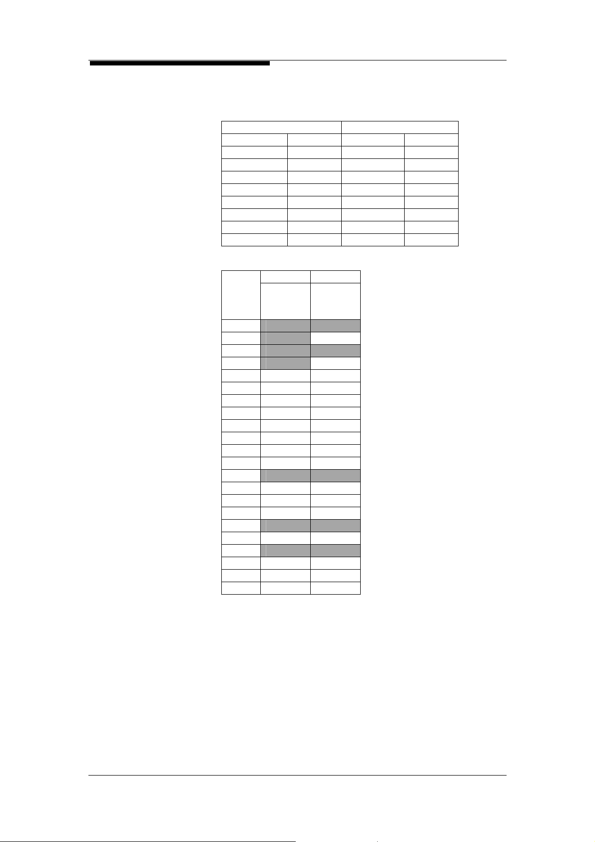
5. System Configuration
5.11. 120 POTS + 24 ADSL System Configuration (STM-1)
Module
Quantity
Slot Allocation
COT Main Shelf RT Main Shelf
Module Qty Module Qty
Shelf 1 Shelf 1
CoPSM 2 RtPSM 2
MPM 1 MPM 1
OIM 2 OIM 2
MLTM 1 MLTM 1
FXO 8 FXS 8
CEoSM 1 REoSM 1
AAM 2
Slot
No.
1
2 AAM
3
4 AAM
5 FXO FXS
6 FXO FXS
7 FXO FXS
8 FXO FXS
9 FXO FXS
10 FXO FXS
11 FXO FXS
12 FXO FXS
13
14 MLTM MLTM
15 OIM OIM
16 OIM OIM
17
18 CEoSM REoSM
19
20 MPM MPM
21 CoPSM RtPSM
22 CoPSM RtPSM
COT RT
Main
Shelf
Main
Shelf
MSAP2000 User Manual V3.0 5-14

5. System Configuration
5.12. 240 POTS + 48 ADSL System Configuration (STM-1)
Module
Quantity
Slot
Allocation
COT Main Shelf RT Main Shelf
Module Qty Module Qty
Shelf 2 Shelf 2
CoPSM 4 RtPSM 4
MPM 1 MPM 1
OIM 2 OIM 2
MLTM 1 MLTM 1
FXO 15 FXS 15
ELM 1 ELM 1
EPM 1 EPM 1
CEoSM 1 REoSM 1
AAM 4
Slot
No.
1 FXO FXS
2 FXO AAM FXS
3 FXO FXS
4 FXO AAM FXS
5 FXO FXS
6 FXO AAM FXS
7 FXO FXS
8 FXO AAM FXS
9 FXO FXS
10 FXO FXS
11 FXO FXS
12 FXO FXS
13 ELM FXO ELM FXS
14 MLTM FXO MLTM FXS
15 OIM FXO OIM FXS
16 OIM OIM
17
18 CEoSM REoSM
19
20 MPM EPM MPM EPM
21 CoPSM CoPSM RtPSM RtPSM
22 CoPSM CoPSM RtPSM RtPSM
COT RT
Main Shelf
Extension Shelf Extension Shelf
1
Main Shelf
1
MSAP2000 User Manual V3.0 5-15

5. System Configuration
5.13. 360 POTS + 72 ADSL System Configuration (STM-1)
Module
Quantity
Slot
Allocation
COT Main Shelf RT Main Shelf
Module Qty Module Qty
Shelf 2 Shelf 2
CoPSM 4 RtPSM 4
MPM 1 MPM 1
OIM 2 OIM 2
MLTM 1 MLTM 1
FXO 23 FXS 23
ELM 1 ELM 1
EPM 1 EPM 1
CEoSM 1 REoSM 1
AAM 6
Slot
No.
1 FXO FXO FXS FXS
2 FXO FXO AAM FXS
3 FXO FXO FXS FXS
4 FXO FXO AAM FXS
5 FXO FXO FXS FXS
6 FXO FXO AAM FXS
7 FXO FXO FXS FXS
8 FXO AAM FXS
9 FXO FXS FXS
10 FXO AAM FXS
11 FXO FXS FXS
12 ELM FXO AAM FXS
13 ELM FXO FXS FXS
14 MLTM FXO ELM FXS
15 OIM FXO MLTM FXS
16 OIM FXO OIM FXS
17 OIM
18 CEoSM REoSM
19
20 MPM EPM MPM EPM
21 CoPSM CoPSM RtPSM RtPSM
22 CoPSM CoPSM RtPSM RtPSM
COT RT
Main
Shelf
Extension
Shelf
1
Main
Shelf
Extension
Shelf
1
MSAP2000 User Manual V3.0 5-16

5. System Configuration
5.14. 480 POTS + 96 ADSL V5 System Configuration (STM-1)
Module
Quantity
concentration 1:4
Slot
Allocation
COT Main Shelf RT Main Shelf
Module Qty Module Qty
Shelf 1 Shelf 3
CoPSM 2 RtPSM 6
MPM 1 MPM 1
OIM 2 OIM 2
V5P 1 MLTM 1
QE1M 1 FXS 30
CEoSM 1 ELM 2
EPM 2
REoSM 1
AAM 8
Slot
No.
1 QE1M MLTM FXS FXS
2 AAM FXS FXS
3 FXS FXS
4 AAM FXS FXS
5 FXS FXS
6 AAM FXS FXS
7 FXS FXS
8 AAM FXS FXS
9 FXS FXS
10 AAM FXS FXS
11 FXS FXS
12 AAM FXS FXS
13 ELM FXS FXS
14 AAM FXS FXS
15 V5P OIM FXS
16 OIM AAM FXS
17 OIM OIM
18 CEoSM REoSM
19
20 MPM MPM EPM EPM
21 CoPSM RtPSM RtPSM RtPSM
22 CoPSM RtPSM RtPSM RtPSM
COT RT
Shelf 1 Shelf 1 Shelf 2 Shelf 3
MSAP2000 User Manual V3.0 5-17
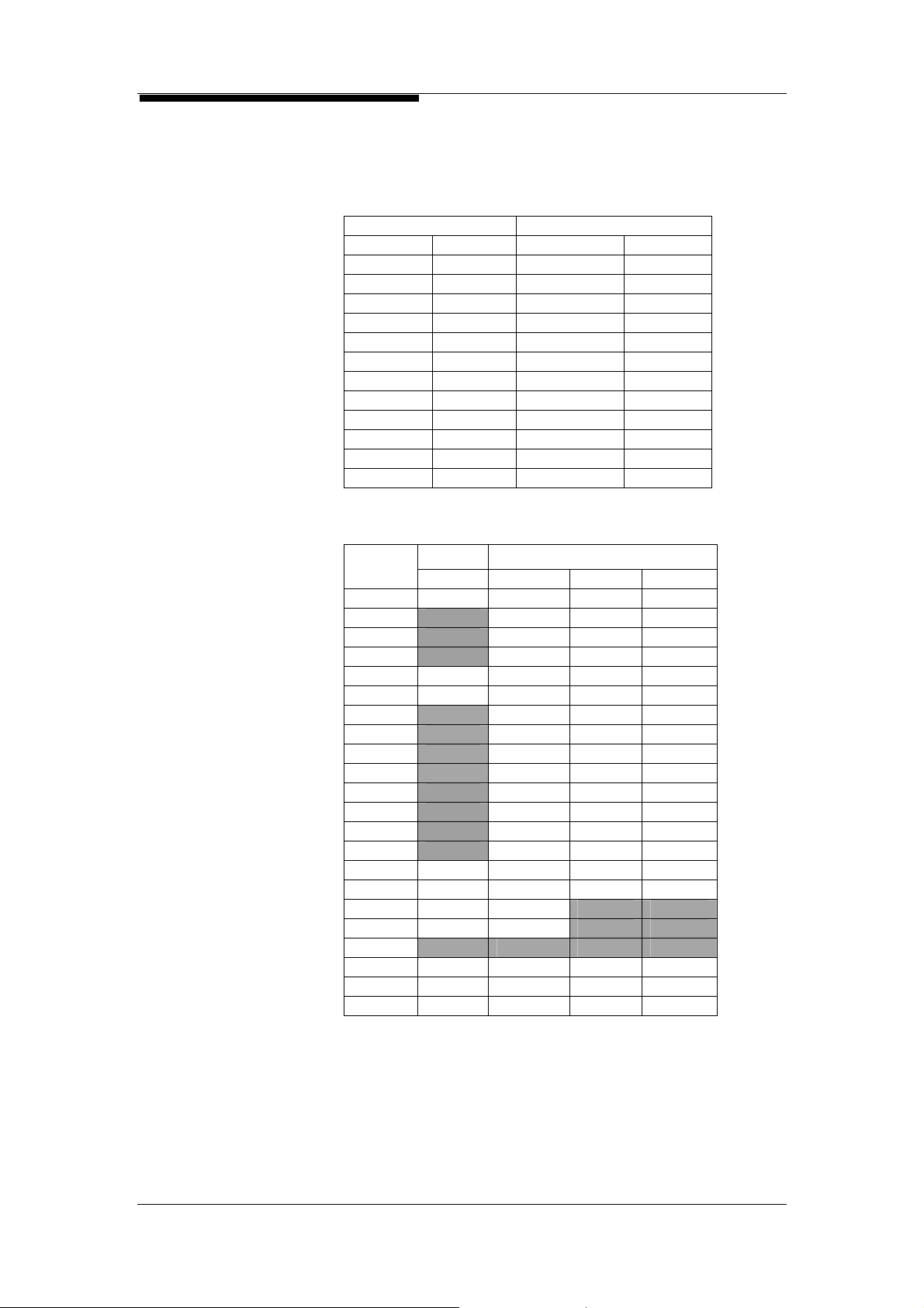
5. System Configuration
5.15. 480 POTS + 96 ADSL + 6 G.SHDSL V5 System
Configuration (STM-1)
Module
Quantity
concentration 1:4
Slot
Allocation
COT Main Shelf RT Main Shelf
Module Qty Module Qty
Shelf 1 Shelf 3
CoPSM 2 CoPSM 2
MPM 1 RtPSM 4
OIM 2 MPM 1
V5P 1 OIM 2
QE1M 3 MLTM 1
CEoSM 1 FXS 30
ELM 2
EPM 2
REoSM 1
AAM 8
GSH 6
Slot
No.
1 QE1M MLTM FXS FXS
2 AAM FXS FXS
3 GSH FXS FXS
4 AAM FXS FXS
5 QE1M GSH FXS FXS
6 QE1M AAM FXS FXS
7 GSH FXS FXS
8 AAM FXS FXS
9 GSH FXS FXS
10 AAM FXS FXS
11 ELM FXS FXS
12 AAM FXS FXS
13 ELM FXS FXS
14 AAM FXS FXS
15 V5P OIM GSH FXS
16 OIM AAM GSH FXS
17 OIM OIM
18 CEoSM REoSM
19
20 MPM MPM EPM EPM
21 CoPSM CoPSM RtPSM RtPSM
22 CoPSM CoPSM RtPSM RtPSM
COT RT
Shelf 1 Shelf 1 Shelf 2 Shelf 3
MSAP2000 User Manual V3.0 5-18

5. System Configuration
5.16. 960 POTS + 120 ADSL + 4 G.SHDSL V5 System
Configuration (STM-1)
Module
Quantity
concentration 1:4
Slot
Allocation
Slot
No.
1 QE1M MLTM GSH FXS FXS FXS
2 QE1M AAM AAM FXS FXS FXS
3 GSH GSH FXS FXS FXS
4 AAM AAM FXS FXS FXS
5 QE1M GSH FXS FXS FXS FXS
6 AAM FXS FXS FXS FXS
7 ELM FXS FXS FXS FXS
8 AAM FXS FXS FXS FXS
9 ELM FXS FXS FXS FXS
10 AAM FXS FXS FXS FXS
11 ELM FXS FXS FXS FXS
12 AAM FXS FXS FXS FXS
13 ELM FXS FXS FXS FXS
14 CEoSM AAM FXS FXS FXS FXS
15 V5P OIM FXS FXS FXS FXS
16 OIM AAM FXS FXS FXS FXS
17 OIM OIM
18 CEoSM REoSM REoSM
19
20 MPM MPM EPM EPM EPM EPM
21 CoPSM CoPSM RtPSM RtPSM RtPSM RtPSM
22 CoPSM CoPSM RtPSM RtPSM RtPSM RtPSM
COT Main Shelf RT Main Shelf
Module Qty Module Qty
Shelf 1 Shelf 5
CoPSM 2 CoPSM 2
MPM 1 RtPSM 8
OIM 2 MPM 1
V5P 1 OIM 2
QE1M 3 MLTM 1
CEoSM 2 FXS 60
ELM 4
EPM 4
REoSM 2
AAM 10
GSH/GSH-R 4
COT RT
Shelf 1 Shelf 1 Shelf 2 Shelf 3 Shelf 4 Shelf 5
MSAP2000 User Manual V3.0 5-19

5. System Configuration
5.17. 1024 POTS + 96 ADSL + Single-ended V5 System
Configuration
Module
Quantity
concentration 1:4
Slot
Allocation
Slot
No.
1 QE1M FXS FXS FXS FXS
2 AAM FXS FXS FXS FXS
3 QE1M FXS FXS FXS FXS
4 AAM FXS FXS FXS FXS
5 MLTM FXS FXS FXS FXS
6 AAM FXS FXS FXS FXS
7 FXS FXS FXS FXS
8 AAM FXS FXS FXS FXS
9 ELM FXS FXS FXS FXS
10 AAM FXS FXS FXS FXS
11 ELM FXS FXS FXS FXS
12 AAM FXS FXS FXS FXS
13 ELM FXS FXS FXS FXS
14 AAM FXS FXS FXS FXS
15 ELM FXS FXS FXS FXS
16 AAM FXS FXS FXS FXS
17 V5P
18 GbE
19
20 MPM EPM EPM EPM EPM
21 CoPSM RtPSM RtPSM RtPSM RtPSM
22 CoPSM RtPSM RtPSM RtPSM RtPSM
COT Main Shelf
Module Qty
Shelf 5
CoPSM 2
RtPSM 8
MPM 1
V5P 1
QE1M 2
ELM 4
EPM 4
GbE 1
MLTM 1
FXS 64
AAM 8
COT
Shelf 1 Shelf 2 Shelf 3 Shelf 4 Shelf 5
MSAP2000 User Manual V3.0 5-20

5. System Configuration
5.18. 480 POTS + 180 ADSL NGN System Configuration
Module
Quantity
Slot
Allocation
COT Main Shelf RT Main Shelf
Module Qty Module Qty
Shelf 1 Shelf 3
CoPSM 2 RtPSM 6
MPM 1 MPM 1
OIM 2 OIM 2
PVM 1 MLTM 1
CEoSM 2 FXS 30
ELM 2
EPM 2
REoSM 2
AAM 15
Slot
No.
1 MLTM FXS FXS
2 AAM AAM FXS
3 FXS FXS FXS
4 AAM AAM FXS
5 FXS FXS FXS
6 AAM AAM FXS
7 FXS FXS FXS
8 AAM AAM FXS
9 FXS FXS FXS
10 AAM AAM FXS
11 FXS FXS FXS
12 AAM AAM FXS
13 ELM FXS FXS
14 CEoSM AAM AAM FXS
15 PVM OIM FXS FXS
16 OIM AAM FXS FXS
17 OIM OIM
18 CEoSM REoSM REoSM
19
20 MPM MPM EPM EPM
21 CoPSM RtPSM RtPSM RtPSM
22 CoPSM RtPSM RtPSM RtPSM
COT RT
Shelf 1 Shelf 1 Shelf 2 Shelf 3
MSAP2000 User Manual V3.0 5-21

5. System Configuration
5.19. 900 POTS + 180 ADSL + 2 G.SHDSL NGN System
Configuration
Module
Quantity
Slot
Allocation
COT Main Shelf RT Main Shelf
Module Qty Module Qty
Shelf 1 Shelf 5
CoPSM 2 CoPSM 2
MPM 1 RtPSM 8
OIM 2 MPM 1
PVM 1 OIM 2
CEoSM 2 MLTM 1
QE1M 1 FXS 57
ELM 4
EPM 4
REoSM 2
AAM 15
GSH/GSH-R 2
Slot
COT RT
No.
Shelf 1 Shelf 1 Shelf 2 Shelf 3 Shelf 4 Shelf 5
1 QE1M MLTM FXS FXS FXS FXS
2 AAM AAM FXS FXS FXS
3 GSH FXS FXS FXS FXS
4 AAM AAM FXS FXS FXS
5 GSH FXS FXS FXS FXS
6 AAM AAM FXS FXS FXS
7 ELM FXS FXS FXS FXS
8 AAM AAM FXS FXS FXS
9 ELM FXS FXS FXS FXS
10 AAM AAM FXS FXS FXS
11 ELM FXS FXS FXS FXS
12 AAM AAM FXS FXS FXS
13 ELM FXS FXS FXS FXS
14 CEoSM AAM AAM FXS FXS FXS
15 PVM OIM FXS FXS FXS FXS
16 OIM AAM FXS FXS FXS FXS
17 OIM OIM
18 CEoSM REoSM REoSM
19
20 MPM MPM EPM EPM EPM EPM
21 CoPSM CoPSM RtPSM RtPSM RtPSM RtPSM
22 CoPSM CoPSM RtPSM RtPSM RtPSM RtPSM
MSAP2000 User Manual V3.0 5-22

5. System Configuration
5.20. 460 POTS + 256 ADSL Single-ended NGN System
Configuration
Module
Quantity
Slot
Allocation
COT Main Shelf
Module Qty
Shelf 3
RtPSM 6
MPM 1
GbE 2
MLTM 1
FXS 29
ELM 2
EPM 2
AAM 16
Slot
No.
1 MLTM FXS FXS
2 AAM AAM FXS
3 FXS FXS FXS
4 AAM AAM FXS
5 FXS FXS FXS
6 AAM AAM FXS
7 FXS FXS FXS
8 AAM AAM FXS
9 FXS FXS FXS
10 AAM AAM FXS
11 FXS FXS FXS
12 AAM AAM FXS
13 ELM FXS FXS
14 AAM AAM FXS
15 ELM FXS FXS
16 AAM AAM FXS
17 PVM
18 GbE GbE
19
20 MPM EPM EPM
21 RtPSM RtPSM RtPSM
22 RtPSM RtPSM RtPSM
COT
Shelf 1 Shelf 2 Shelf 3
MSAP2000 User Manual V3.0 5-23

5. System Configuration
5.21. 944 POTS + 192 ADSL Single-ended NGN System
Configuration
Module
Quantity
Slot
Allocation
COT Main Shelf
Module Qty
Shelf 5
RtPSM 10
MPM 1
GbE 2
MLTM 1
FXS 59
ELM 4
EPM 4
PVM 1
AAM 16
Slot
COT
No.
Shelf 1 Shelf 2 Shelf 3 Shelf 4 Shelf 5
1 MLTM FXS FXS FXS FXS
2 AAM AAM FXS FXS FXS
3 FXS FXS FXS FXS FXS
4 AAM AAM FXS FXS FXS
5 FXS FXS FXS FXS FXS
6 AAM AAM FXS FXS FXS
7 FXS FXS FXS FXS FXS
8 AAM AAM FXS FXS FXS
9 ELM FXS FXS FXS FXS
10 AAM AAM FXS FXS FXS
11 ELM FXS FXS FXS FXS
12 AAM AAM FXS FXS FXS
13 ELM FXS FXS FXS FXS
14 AAM AAM FXS FXS FXS
15 ELM FXS FXS FXS FXS
16 AAM AAM FXS FXS FXS
17 PVM
18 GbE GbE
19
20 MPM EPM EPM EPM EPM
21 RtPSM RtPSM RtPSM RtPSM RtPSM
22 RtPSM RtPSM RtPSM RtPSM RtPSM
MSAP2000 User Manual V3.0 5-24

6. System Design
Table of Contents
6. System Design ............................................... ........................................................................6-1
6.1. System Capacity........................................................................ .... .... ....... .... .... .... .6-1
6.2. Clock Synchronization...........................................................................................6-3
6.3. Redundancy and Protection Design......................................................................6-4
6.4. Reliability ...............................................................................................................6-6
6.5. Ethernet over SDH Design........................................................... .........................6-7
6.6. IP DSLAM Design..................................................................................................6-8
MSAP2000 Technical Manual V3.0 6-i

6. System Design
THIS PAGE IS LEFT BLANK
MSAP2000 Technical Manual V3.0 6-ii

6. System Design
6. System Design
6.1. System Capacity
Maximum
Telephone
Capacity
Maximum V5
Capacity
Maximum VoIP
Capacity
Maximum ADSL
Capacity
Maximum E1
Capacity
Combined
Analog/ADSL/E1
System
MSAP2000 is designed to provide both capabilities of the TDM based
on SDH and Packet based on ETHERNET. The SDH is based on
STM-1/STM-4 system architecture. Its system capacity can reach up
to 63/252 E1, which is equal to 1890/7560 lines of 64Kbps (DS0)
bandwidth. Each DS0 can independently transmit TDM or IP data.
Subscriber bandwidth can be increased based on a granularity of
64Kbps. MSAP2000’s built-in Digital Cross-Connect functions can
allow all DS0 Timeslots to be cross-connected.
Each FXS/FXO Module provides 16 telephone user interfaces.
When fully loaded, up to 16 FXS modules can provide 256 subsc riber
interfaces in one single shelf. And in one MSAP2000’s COT and RT,
each node can support up to 8 shelves and that will lead to 1890
telephone user interfaces without concentration.
One V5.2 System supports up to 16 E1 interfaces, and can pr ovide
1:N concentrated operation for up to 7560 voice subscribers. One
V5P Module supports 4 independent V5.2 Systems, meaning that one
MSAP2000 will support 4 V5.2 Systems, and provide 7560 voice
channels.
When interfacing the soft-switch, MSAP200 can be plugged w ith PVM
modules with N+1 protection scheme. Each PVM can provide up-to
256 G.711 simultaneous calls at the same time. The number of
subscriber lines can be up to 1890. Concentration ratio can be lower
by adding more PVM modules.
Each AAM (ADSL Access Module) supports 12 ADSL2/2+ interfaces,
and each shelf will hold 16 AAMs, to provide 192 ADSL subscriber
interfaces. One MSAP2000 can support up to 1536 ADSL subscriber
interfaces. The up-link can use GbE for higher bandwidth requirement.
Each QE1M supports 4 ITU-T G.703 E1 interfaces. Each self can
support 16 QE1M Modules, which will provide 63 E1 data subscriber
interfaces. When QE1M is setup as Fractional E1, the maximum
capacity for E1 data subscriber usage is 512Kbps (provided that the
average bandwidth for each Fractional E1 is 4 DS0s).
These modules may be randomly combined, to satisfy individual
requirements. Telephone, Data (E1) or ADSL Modules can be
added, until the System’s capacity 1890 (DS0) is full.
MSAP2000 Technical Manual V3.0 6-1

6. System Design
Module Name Subscriber
FXS 16 256 1890 (STM-1) /
FXS-P 8 128 1024 (STM-1)/
2W/4W E&M 4 64 512 (STM-1) /
QE1M 4 63 63 (STM-1) /
GSH 1 16 63 (STM-1) /
ETH 1 16 63 (STM-1)
CEoSM 1 16 63 (STM-1)
N64M 1 16 63 (STM-1)
LULT 4 64 512
AAM 12 96 756 (GbE uplink)*
ESM 8 128 512(GbE uplink)+
REoSM 8 128 128
*For xDSL services, the limitation of the ports per system will depend on the exact band-width
requirement. And there is a best effort method to increase the allowed port density. It is suggested
that user shall consult with ZyXEL
clear
Qty/Card
Subscriber
Subscriber Qty/System
Qty/Shelf
7560 (STM-4)
Non-Blocking
Non-Blocking
252(STM-4)
252 (STM-4)
2Mbps per port
2Mbps per port
2Mbps per port
2Mbps per port
2Mbps per port
2Mbps per port
support team to find out the best solution when the application is
刪除: ZyFLEX
+ Similar to xDSL, the total ETH ERNET port through ESM is also band -width dependent. Please
consult ZyXEL
support team to find best solution for deployment.
MSAP2000 Technical Manual V3.0 6-2
刪除: ZyFLEX

6. System Design
6.2. Clock Synchronization
COT Timing
Clock Priority
RT Timing
GSH-R Timing
Output
Synchronization
The MSAP2000 provides two Building Integrated Timing Supply
System (BITS) clock interfaces to connect with BITS equipment for
acquiring high precision clock. The BITS interface supports 2Mbit/s
and 2MHz clock inputs. It has clock detection and switchover functions.
The clock output with 2MHz is also provided. And without BITS, COT
can also have Line timing or internal timing to meet the precision of
clock.
External Timing (BITS): ITU-T G.703 square waves (2048 KHz) of
Framed E1 signals.
Line Timing: Selects any synchronous QE1M E1 interface input signals
from the COT network side/end
Internal Timing: MPM internal clock. Its frequency accuracy is <±
20 ppm.
MSAP2000 can select its synchronous time source via LCT or NMS.
When the main clock source fails, the System can switch to the
secondary clock source, based on previous setup priorities.
MSAP2000’s RT accepts the following two types of timing sources:
Line Timing: each RT automatically selects a synchronous signal
from any trunk interface/transmission link input signals from COT
whenever the link to RT has been established
Internal Timing: RT will run in MPM internal clock if transmission
links experiencing link failure. Its frequency accuracy is <± 32
ppm.
MSAP2000’s GSH Module can connect to the subscriber end GSH-R
(G.SHDSL modem), to provide data leased line services. GSH-R
supports Loop Timing and Internal Timing.
Loop Timing: GSH-R selects a synchronous clock from the Loop’s
input signals.
Internal Timing: GSH-R internal clock. Its frequency accuracy is
<±
32 ppm.
The Jumper on the MPM’s circuit board in MSAP2000 can be used to
setup output synchronization for 2048 KHz square waves or 2Mb/s and
Framed all “1” E1 signals. The Clock output provides the timing source
for other equipment to be synchronized to the networking timing.
MSAP2000 Technical Manual V3.0 6-3
 Loading...