


machine numbers |
A13P02D |
Thanks for choosing Zenith!
h o o k u p d i r e c t o r y
p a g e 3
y o u r o n - s c r e e n m e n u s |
14 |
p a g e |
i n d e x
p a g e 26
Thanks for choosing
p a g e
p a g e
3
14
p a g e 26
o p e r a t i n g g u i d e / w a r r a n t y
RECORD YOUR MODEL NUMBER (Now, while you can see it)
The model and serial number of your new TV are located on the back of the TV cabinet. For your future convenience, we suggest that your record these numbers here:
MODEL NO.____________________________________
SERIAL NO.____________________________________
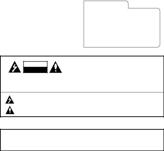
WARNING
RISK OF ELECTRIC SHOCK
DO NOT OPEN
The lightning flash with arrowhead symbol, within an equilateral triangle, is intended to alert the user to the presence of uninsulated “dangerous voltage” within the product’s enclosure that may be of sufficient magnitude to constitute a risk of electric shock to persons.
The exclamation point within an equilateral triangle is intended to alert the user to the presence of important operating and maintenance (servicing) instructions in the literature accompanying the appliance.
CAUTION: To Prevent Electric Shock, Match wide blade of plug to wide slot, fully insert.
ATTENTION: Pour éviter les chocs électriques, introduire la lame la plus large de la fiche dans la borne correspondante de la prise et pousser jusqu’au fond.
This reminder is provided to call the cable TV system installer’s attention to Article 820-40 of the National Electric Code (U.S.A.). The code provides guidelines for proper grounding and, in particular, specifies that the cable ground shall be connected to the grounding system of the building, as close to the point of the cable entry as practical.
This equipment has been tested and found to comply with the limits for a Class B digital device, pursuant to Part 15 of the FCC Rules. These limits are designed to provide reasonable protection against harmful interference when the equipment is operated in a residential installation. This equipment generates, uses and can radiate radio frequency
energy and, if not installed and used in accordance with the instruction manual, may cause harmful interference to radio communications. However, there is no guarantee that interference will not occur in a particular installation. If this equipment does cause harmful interference to radio or television reception, which can be determined by turning
the equipment off and on, the user is encouraged to try to correct the interference by one or more of the following measures: • Reorient or relocate the receiving antenna.
•Increase the separation between the equipment and receiver.
•Connect the equipment into an outlet on a circuit different from that to which the receiver is connected.
•Consult the dealer or an experienced radio/TV technician for help.
Do not attempt to modify this product in any way without written authorization from Zenith Electronics Corporation. Unauthorized modification could void the user’s authority to operate this product.
RECORD YOUR MODEL NUMBER (Now, while you can see it)
WARNING
RISK OF ELECTRIC SHOCK
DO NOT OPEN
WARNING:
TO REDUCE THE RISK OF ELECTRIC SHOCK DO NOT REMOVE COVER (OR BACK). NO USER SERVICEABLE PARTS INSIDE. REFER SERVICING TO QUALIFIED SERVICE PERSONNEL.
WARNING:
TO PREVENT FIRE OR SHOCK HAZARDS, DO NOT EXPOSE THIS PRODUCT TO RAIN OR MOISTURE.
POWER CORD POLARIZATION:
NOTE TO CABLE/TV INSTALLER:
REGULATORY INFORMATION:
CAUTION:
INSTALLATION |
GETTING STARTED |
P A G E 3 |
|
|
|
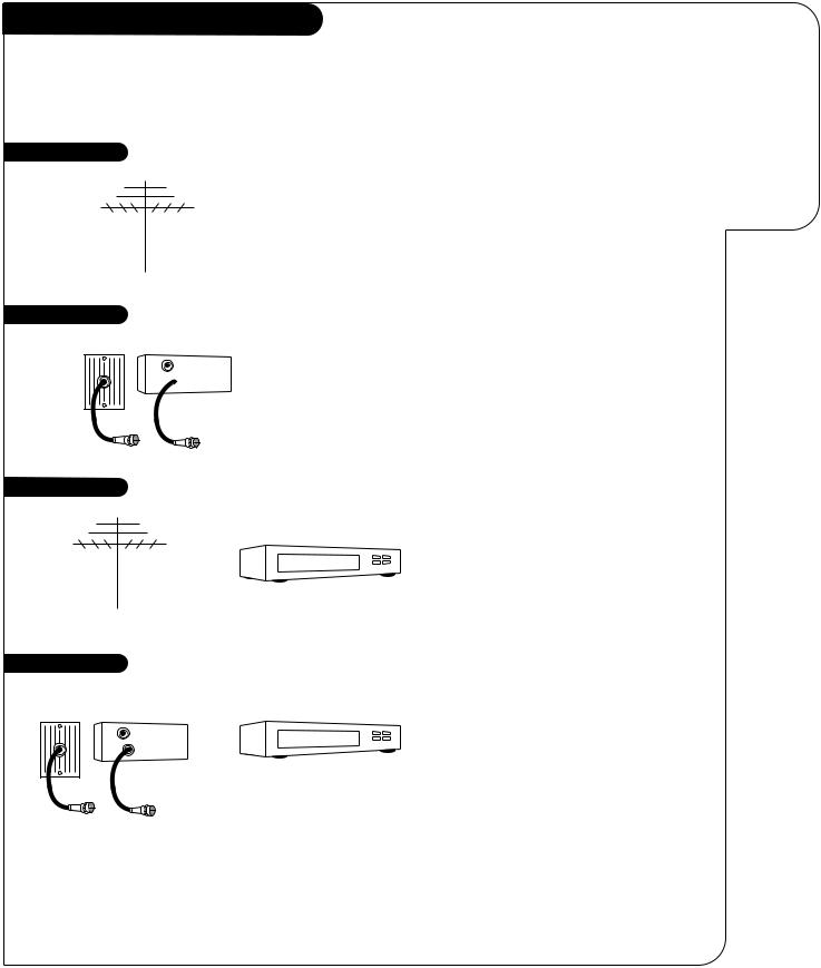
Hook-Up Directory
IMPORTANT!!
Use this page to decide where you need to begin your setup. First, find the line below that best describes what you want to do, then go to that page number. Note: Design and specifications are subject to change without prior notice.
If you are using an antenna and no other equipment, go to . . . . . . . . . . . . . . . . . . page 4
If you have cable and no other equipment, go to . . . . . . . . . . . . . . . . . . . . . . . . . page 5
Cable TV wall jack
In |
Cable box |
Out 
Antenna with VCR |
If you are using an antenna and have a VCR, go to . . . . . . . . . . . . . . . . . . . . . . . |
page 6 |
This page will direct you to which page to go to for proper hookup of your Entertainment Machine.
Cable and VCR |
If you have cable and a VCR, go to . . . . . . . . . . . . . . . . . . . . . . . . . . . . . . . . . . |
page 7 |
Cable TV |
|
|
wall jack |
|
|
In |
Cable box |
|
Out |
|
|
3369-o
Hook-Up Directory
IMPORTANT!!
Antenna only
Cable only
Cable TV wall jack
In |
Cable box |
Out
Antenna with VCR
Cable and VCR
Cable TV wall jack
In |
Cable box |
Out
This page direct you which page to go to f proper hoo up of your Entertainme Machine.
P A G E 4 |
INSTALLATION |
STANDARD |
|
|
|
Connect an
antenna
to your
Entertainment
Machine.
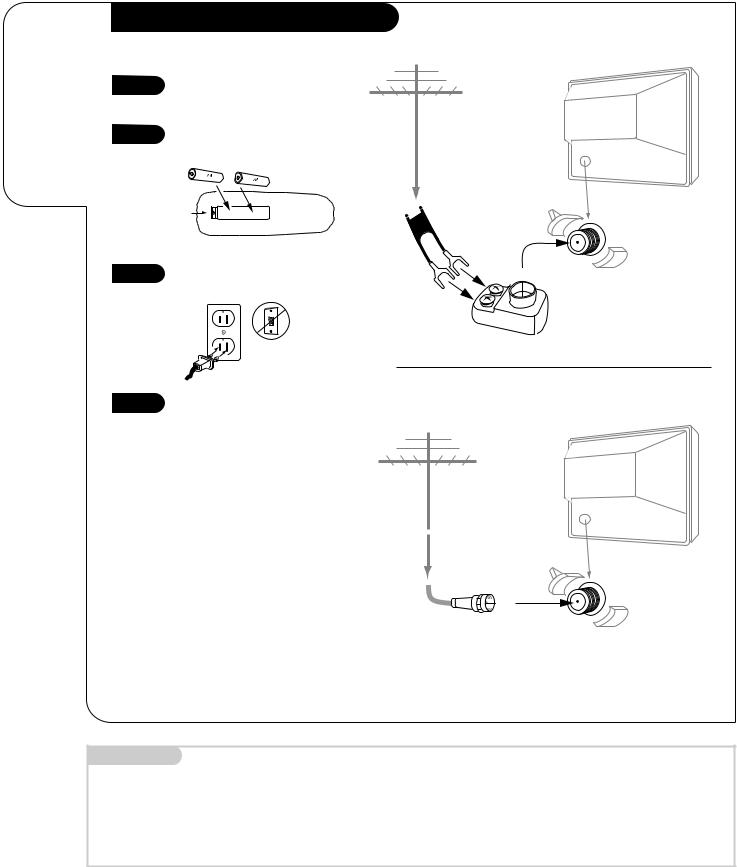
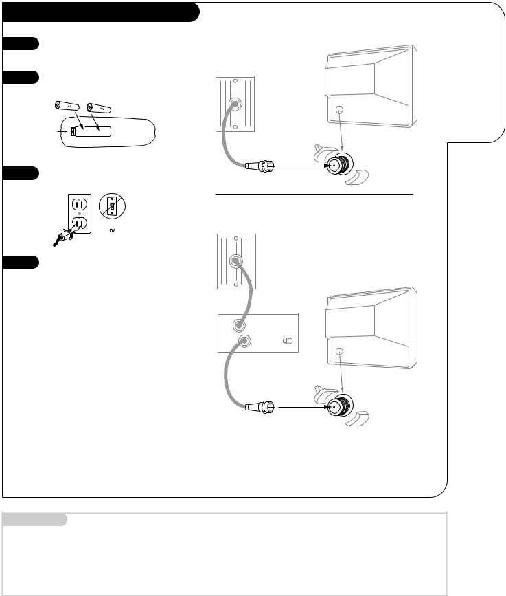
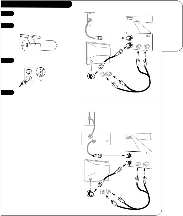
Hook Up Your Antenna to the TV
Flat-Wire Antenna to Adapter
1
2
Hook up your Entertainment Machine, see diagrams at right.
Remove the back of the remote and put in two AA batteries matching + with + and - with -.
Antenna |
Typical TV back |
|
back of |
|
remote |
3 |
Plug in your TV. Do not plug it |
|
into a switched outlet. |
120V
60Hz
Flat wire (300 ohm)
Antenna
300/75 ohm Adapter
Round Antenna Wire
4 |
Go to page 8 to select your |
|
|
Antenna setup and page 9 to |
|
|
Auto Program your Entertainment |
|
|
Machine. |
|
|
|
Typical TV back |
|
If you have a 75 ohm RF cable, |
Antenna |
|
|
|
|
then you don’t need any adapters! |
|
|
Remember, when screwing RF |
|
|
cables onto jacks, clockwise tight- |
|
|
ens, and counterclockwise loosens. |
|
A 300 to 75 ohm adapter is not |
RF coaxial wire |
TV back panel |
(75ohm) |
(expanded view) |
|
included with your Zenith |
|
|
Entertainment Machine. |
|
|
|
|
Antenna |
Mini glossary
75 OHM RF CABLE |
The wire that comes from an off-air antenna or cable service provider. Each end looks like a hex shaped nut with a wire |
|
sticking through the middle, and it screws onto the threaded jack on the back of your TV. |
300 TO 75 OHM ADAPTER |
A small device that connects a two-wire 300 ohm antenna to a 75 ohm RF jack. They are usually about an |
|
inch long with two screws on one end and a round opening with a wire sticking out on the other end. |
3368-O
Hook Up Your Antenna to the TV
Connect an antenna to your EntertainMachin 1
Antenna |
Typical TV back |
2
back of |
Flat wire |
remote |
(300 ohm) |
3 |
Antenna |
|
|
|
300/75 ohm |
|
Adapter |
120V
60Hz
4
Typical TV back
Antenna
If you have a 75 ohm RF cable, then you don’t need any adapters!
Remember, when screwing RF
cables onto jacks, clockwise tightens, and counterclockwise loosens.
RF coaxial wire
A 300 to 75 ohm adapter (75ohm)is not included with your Zenith 

 Entertainment Machine.
TV back panel (expanded view)
Antenna
Hook Up Your Cable (CATV) to the TV
1 |
Hook up your Entertainment |
|
Machine, see diagrams at right. |
2 |
Remove the back of the remote |
and put in two AA batteries |
|
|
matching + with + and - with -. |
|
back of |
|
remote |
3 |
Plug in your TV. Do not plug it |
|
into a switched outlet. |
|
120V |
|
60Hz |
4 |
Go to page 8 to select your |
|
Antenna setup and page 9 to |
|
Auto Program your Entertainment |
|
Machine. |
|
If you’re using a cable box, leave your |
|
TV on channel 3 or 4 and use your |
|
cable box to change channels. |
|
Remember, when screwing RF cables |
|
onto jacks, clockwise tightens, and |
|
counterclockwise loosens. |
|
If you’re using a cable box, Auto- |
|
Program (page 8) might only find the |
|
channel your cable service is on |
|
(usually channel 3 or 4). Don’t worry, |
|
that’s all you need! |
INSTALLATION |
STANDARD |
P A G E 5 |
|
|
|
Without Cable Box |
Connect |
|
cable to your |
|
Entertainment |
|
Machine. |
Cable TV |
|
wall jack |
Typical TV back |
|
RF coaxial wire (75ohm)
Antenna
With Cable Box
Cable TV wall jack
Typical TV back
In |
Cable box |
|
Out |
output |
3 4 |
|
switch |
|
RF coaxial wire (75ohm)
Antenna
Mini glossary
CABLE SERVICE The wire that supplies all your cable TV (CATV) stations.
3368-O
Hook Up Your Cable (CATV) to the TV
Connect cable to y
1 Entertainme Machine.
Cable TV wall jack
2 |
Typical TV back |
|
back of remote
RF coaxial wire (75ohm)
3
Antenna
Cable TV 120V wall jack
60Hz
4
|
|
|
If |
you’re |
using |
a cable box, leave yourTypical TV back |
||
|
|
|
|
|
|
|
In |
Cable box |
|
|
|
TV |
on |
channel 3 |
or 4 and use your |
||
|
|
|
||||||
|
|
|
cable |
box |
to change channelsOut output. |
|||
switch 3 4
Remember, when screwing RF cables onto jacks, clockwise tightens, and counterclockwise loosens.
If you’re using a cable boRF coax,ial wireAuto(75ohm) - Program (page 8) might only
 find the
 channel your cable service is on
Antenna
(usually channel 3 or 4). Don’t worry, that’s all you need!

P A G E 6 |
INSTALLATION |
STANDARD |
|
|
|
Connect your off-air antenna and VCR to your Entertainment Machine.
Hook Up Antenna and VCR to the TV |
Flat-Wire Antenna to Adapter and Audio/Video Cables |
1 |
Hook up your Entertainment |
|
Machine, see diagrams at right. |
2 |
Remove the back of the remote |
and put in two AA batteries |
|
|
matching + with + and - with -. |
|
back of |
|
remote |
3 |
Plug in your TV. Do not plug it |
|
into a switched outlet. |
Antenna |
Flat wire |
|
VCR back |
(300ohm) |
|
|
|
VCR back AV panel |
|
300/75 ohm |
In |
Output |
Adapter |
|
switch 3 4 |
|
Out |
Video Audio |
Typical
TV back
|
120V |
|
60Hz |
4 |
Go to page 8 to select your |
|
Antenna setup and page 9 to |
|
Auto Program your Entertainment |
|
Machine. |
|
Remember, when screwing |
|
RF cables onto jacks, clockwise |
|
tightens, and counterclockwise |
|
loosens. |
|
A/V cables or adapters are not |
|
included with your Zenith |
|
Entertainment Machine. |
Video |
Audio |
In |
|
Round Cable to VCR and Audio/Video Cables
Over-the-Air
Antenna
|
|
VCR back |
Cables not included with TV |
VCR back AV panel |
|
|
In |
Output |
|
|
switch 3 4 |
|
Out |
Video Audio |
Typical
TV back
Video |
Audio |
In |
|
3368-O
Hook Up Antenna and VCR to the TV
Connect off-air
antenna 1 VCR to
Entertainment
Machin 2
Antenna |
|
Flat wire |
VCR back |
(300ohm) |
|
|
VCR back AV panel |
back of |
300/75 ohm |
In |
Output |
|
remote |
||||
Adapter |
|
switch 3 4 |
||
|
|
|||
|
|
Out |
Video Audio |
|
3 |
|
Typical |
|
|
|
TV back |
|
120V
60Hz
4
Video |
Audio |
In |
|
Remember, when screwing
RF cables onto jacks, clockwise
tightens, and counterclockwise |
|
loosens. |
Over-the-Air |
|
Antenna |
A/V cables or adapters are not included with your Zenith Entertainment Machine.
Cables not included with TV
Typical
TV back
Video |
Audio |
In |
|
VCR back
VCR back AV panel
In Output 
switch 3 4
Out Video Audio
Hook Up Your Cable (CATV) and VCR
1 |
Hook up your Entertainment |
|
Machine, see diagrams at right. |
2 |
Remove the back of the remote |
and put in two AA batteries |
|
|
matching + with + and - with -. |
|
back of |
|
remote |
3 |
Plug in your TV. Do not plug it |
|
into a switched outlet. |
|
120V |
|
60Hz |
4 |
Go to page 8 to select your |
|
Antenna setup and page 9 to |
|
Auto Program your Entertainment |
|
Machine. |
|
Leave your VCR and your television |
|
tuned to channel three and use |
|
the cable box to change channels. |
|
Remember, when screwing in RF |
|
cables onto jacks, clockwise tight- |
|
ens, and counterclockwise loosens. |
|
No A/V cables are included with |
|
your Zenith Entertainment |
|
Machine. |
INSTALLATION |
STANDARD |
P A G E 7 |
|
|
|
Cable Service and Audio/Video Cables
Cable TV |
|
Connect |
wall jack |
|
your VCR and |
|
|
|
|
|
Cable to your |
|
VCR back |
Entertainment |
|
|
Machine. |
VCR back AV panel |
|
|
Round wire (75ohm) |
Output |
|
In |
4 |
|
|
switch 3 |
|
Out |
Video Audio |
|
Typical
TV back
Video |
Audio |
|
|
In |
|
Cable Service with a Cable Box and Audio/Video Cables
Cable TV wall jack
In |
Cable box |
VCR back |
Out |
output |
|
|
switch 3 4 |
|
|
VCR back AV panel |
|
|
Round wire (75ohm) |
Output |
|
In |
|
|
|
switch 3 4 |
|
Out |
Video Audio |
Typical
TV back
Video |
Audio |
In |
|
3368-O
Hook Up Your Cable (CATV) and VCR
Cable TV wall jack
1
2
Round wire (75ohm)
back of remote
Typical
TV back
3
Video |
Audio |
|
|
In |
|
120V
60Hz
4
Cable TV wall jack
Leave your VCR and your television tuned to channel three and use the cable box to change channels.
Remember, when screwing in RF
|
|
|
|
cables onto jacks, clockwise tight- |
|
|
|
|
|
||
|
|
|
|
In |
Cable box |
|
|
|
|
ens, and counterclockwise loosens. |
|
|
|
|
|
Out |
output |
|
|
|
|
|
swi ch 3 4 |
|
|
|
|
No A/V cables are included with |
|
|
|
|
|
||
|
|
|
|
your Zenith Entertainment |
|
|
|
|
|
Machine. |
Round wire (75ohm) |
Typical
TV back
Video |
Audio |
In |
|
VCR back
VCR back AV panel
In Output 
switch 3 4
Out Video Audio
VCR back
VCR back AV panel
In Output 
switch 3 4
Out Video Audio
Connect your VCR an Cable to yo Entertainme Machine.
P A G E 8 |
INSTALLATION |
SPECIFY TYPE OF SIGNAL |
|
|
|
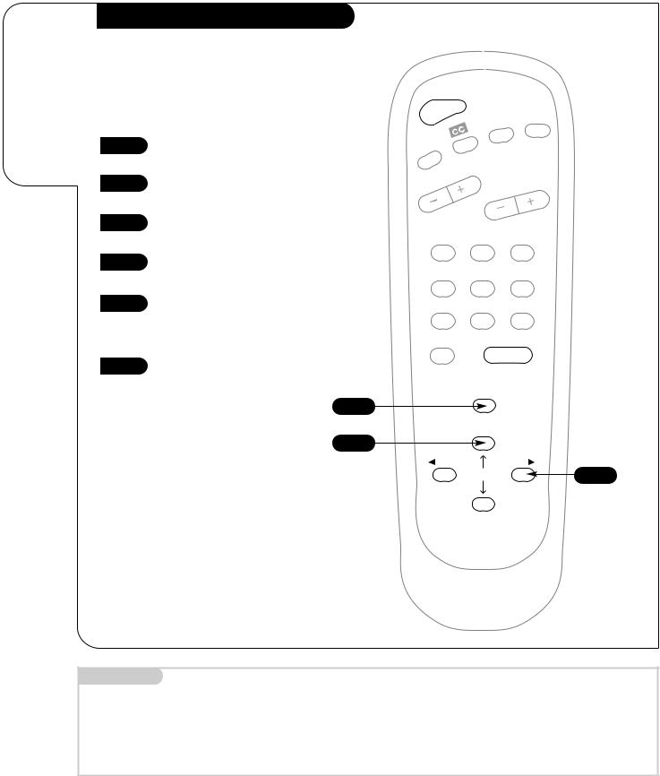
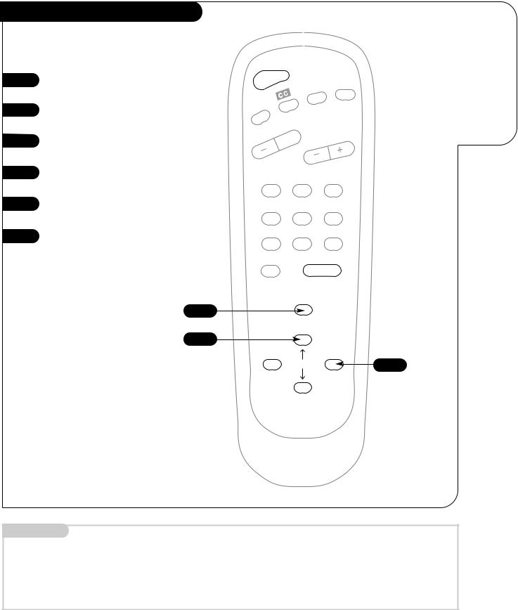
Select the type of signal your
Entertainment Machine will receive.
Antenna (Select Air or Cable Service)
Select your antenna setup before using
Auto Program (Channel Search).
1 |
Press MENU to access the feature |
|
selection Menu. |
||
|
||
2 |
Using the UP/DOWN Select |
|
|
||
|
arrows, choose Setup. |
|
3 |
Press the RIGHT Adj arrow to |
|
access the Setup Menu. |
||
|
||
4 |
Using the UP/DOWN Select |
|
arrows, choose Antenna. |
||
|
||
5 |
Press a RIGHT/LEFT Adj arrow to |
|
choose Off-Air-Antenna, or Cable |
||
|
||
|
TV if you subscribe to cable ser- |
|
|
vice. |
|
6 |
Go to page 9. |
|
|
1
2/4
POWER
|
|
MUTE |
|
FLSHBK |
|
TIMER |
|
|
VOLUME |
CHANNEL |
|
|
||
1 |
2 |
3 |
4 |
5 |
6 |
7 |
8 |
9 |
0 |
|
ENTER |
|
MENU |
|
ADJ |
ADJ |
3/5
Mini glossary
Antenna |
Specifies what type of incoming signal your TV will be receiving. |
AIR |
Signal is received by an over the air antenna. |
CABLE |
Pay TV Signal is provided by a cable service. |
3368-O
Select Antenna (Select Air or Cable Service)
type of signal your Entertainment Machine will receive.
1
2
3
4
POWER
TIMER
VOLUME
1
4
MUTE
FLSHBK
|
CHANNEL |
2 |
3 |
5 |
6 |
5 |
7 |
8 |
9 |
|
0 |
|
ENTER |
6 |
|
|
|
|
1 |
MENU |
|
|
|
|
|
|
2/4 |
|
|
|
ADJ |
|
ADJ |
SELECT |
3/5 |
|
INSTALLATION |
CHANNEL SEARCH |
P A G E 9 |
|
|
|
Auto Program
1 |
Press MENU to access the feature |
|
selection Menu. |
||
|
||
2 |
Using the UP/DOWN Select |
|
|
||
|
arrows, choose Setup. |
|
3 |
Press the RIGHT Adj arrow to |
|
access the Setup Menu. |
||
|
||
4 |
Using the UP/DOWN Select |
|
arrows, choose Auto Program. |
||
|
||
5 |
Press the RIGHT Adj arrow to |
|
begin the channel search. |
||
|
||
6 |
When the channel search is com- |
|
plete, you can choose a channel |
for TV viewing.
POWER
MUTE
FLSHBK
TIMER
VOLUME 
1
4
7
0
1
2/4
 ADJ
ADJ
|
CHANNEL |
2 |
3 |
5 |
6 |
8 |
9 |
|
ENTER |
MENU
ADJ
3/5
Use Auto Program to automatically find and store all of the stations available in your area.
Mini glossary
AUTOPROGRAM Auto Program is how your Entertainment Machine finds all the channels available in your area and stores them into memory.
3368-O
 Loading...