


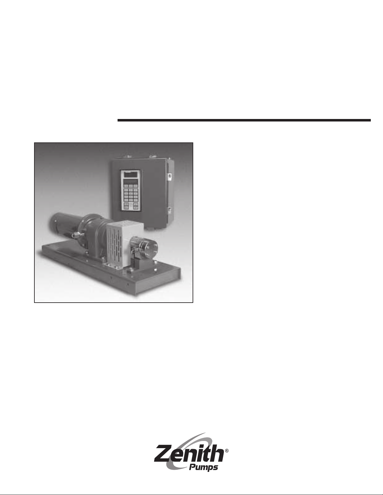
B-9000 Series
Zenith B-9000 Series, B-9000-.05, B-9000-.3, B-9000-.6, B-9000-2.4 Installation, Care And Maintenance
...
Zenith®Pumps
Installation,
Care and
Maintenance
Zenith
®
Chemical Duty
Gear Pumps
B-9000
Gear Pumps

2
Zenith
®
Thoroughly read and understand this entire manual
before installation and operation of pump.
Benefits
Specifications
In 1926, Zenith Pumps was approached
by the synthetic fiber industry to design
a pump that would provide precise,
pulseless and repeatable flow while
ensuring ultimate product quality. The
options then were the same as those in
the chemical process industry today—
diaphragm, lobe, coarse gear, piston,
plunger and screw pumps. Each has
problems with pulsation, flow inaccuracies, multiple seal areas and slip, which
require constant calibration, high maintenance and extended downtimes.
Zenith Pumps met the challenge
and designed a rotary external gear
pump of unique precision and simplicity.
Manufacturing techniques were developed to hold tolerances to ±.00005",
minimizing internal clearances and
assuring accurate and precise metering.
The pump’s simplistic design of only
three moving parts – two metering gears
and a drive shaft – provided long life
and reduced maintenance.
For years, engineers have relied on
Zenith to provide precision fluid handling solutions for their most difficult
pumping applications. Zenith gear
pumps can be found wherever precise,
pulseless, and repeatable metering of
fluids is required.
High Accuracy — Stable, repeatable
flows are assured even under varying
conditions of temperature, viscosity and
pressure.
Precision Construction — Ground and
lapped components allow for operating
clearances to .00015" and provide high
volumetric efficiency.
Minimum Pulsation — Unique design
offers virtually pulseless flow without
valves or flexible elements to hinder
performance.
Active Flowmeter Concept —
Unparalleled mechanical precision,
combined with the closed loop set point
accuracy, ensures an exact volume
per revolution without expensive flow
meters.
Low Cost of Ownership — With only
three moving parts and 400 series
stainless steel construction, the pump
provides excellent corrosion resistance
for most chemical processes, and is
through-hardened to 54 Rcor better for
maximum life.
Experience — Zenith has over 74
years of application experience with
engineers available 24 hours a day to
support your precision fluid metering
needs.
Capacities (cc/rev): 0.05, 0.3, 0.6, 1.2,
2.4, 4.5, 9.0, 15, 30, 45, 90
Recommended Speed:
.05 to 30 cc/rev, up to 500 RPM
45 & 90 cc/rev, up to 300 RPM
Flow Range:
up to 27,000 cc/Minute, (7 GPM)
Inlet Pressure: 300 psi (20 Bar) Max.
Outlet Pressure: 1000 psi (70 Bar) Max.
Differential Pressure:
20 to 1000 psi. (viscosity dependent)
Temperature:
0° F (-18° C) Minimum
400° F (205° C) Maximum (with magnetic
coupling seal)
645° F (340° C) Maximum (dependant on
shaft seal materials)
Seals:
Single Mechanical, Double Lip,
Packed or Magnetic
Rotation:
Clockwise (CW) facing drive shaft
Port Connections:
Metric thread or SAE 61 Standard
Optional Port Adapters:
M12 X 1/4" NPT . . . . . . . . . 0.05 – 2.4 cc/rev
1/2" SAE X 1/2" NPT
. . . . . . 4.5 – 9.0 cc/rev
3/4" SAE X 3/4" NPT
. . . . . . . 15 – 30 cc/rev
1-1/4" SAE X 1-1/4" NPT. . . 45 – 90 cc/rev
Optional Band heaters:
150 Watt, 115 VAC . . . . 0.05 – 2.4 cc/rev
325 Watt, 115 VAC . . . . 4.5 – 9.0 cc/rev
650 Watt, 230 VAC . . . . . 15 – 30 cc/rev
1500 Watt, 230 VAC . . . 45 – 90 cc/rev

3
Design
Zenith’s B-9000 Series precision metering pumps utilize a rotary external spur
gear which dispenses an exact volume
of fluid per shaft revolution (cc/rev).
Precision ground and lapped construction, including alignment dowels,
allows for close control of operating
clearances. This ensures precise,
pulseless and repeatable flow under
varying process conditions.
Integrated closed loop speed control and a compact motor driver system
maintains up to .01% accuracy of set
point speeds and also accepts automated interfaces.
The B-9000 Series is constructed of
400 series stainless steel, providing
excellent bearing qualities (hardness 54
Rc) and corrosion resistance for most
chemical processes. The pump offers
increased uptime while minimizing maintenance due to its simple design of only
three moving parts.
The B-9000 Series is a new generation of Zenith’s traditional B-Series pump.
While maintaining precise flow characteristics, its optimum gear design
reduces bearing loads, while increasing
speed capability. The pump allows
direct piping and shaft engagement and
includes a single mechanical shaft seal,
(other seal types available).
Operation
Fluid enters the pump through the inlet
port located in the front plate and fills
the gear pocket. As the gears rotate, a
precise amount of fluid is trapped by the
side walls of the gear pockets and gear
teeth.
The metered fluid is transported by
the rotation of the gears to the discharge
side of the pump where the gear teeth
come into mesh. This action forces the
fluid out of the gear teeth and through
the outlet port located in the front plate.
The pressure developed is determined
by the pump size, the gear clearances,
pump speed, fluid viscosity and impedance to flow.
Pump speed is limited by practical
considerations. If a high viscosity fluid is
being metered and pump speed is
increased beyond a certain point, the
fluid may not be able to fill the gear
teeth spaces, and the pump will not
obtain enough fluid to maintain normal
volumetric efficiency. Lack of sufficient
fluid is called starvation or cavitation.
This can be remedied by increasing the
inlet pressure or reducing pump speed.
See table 1 on page 5.
Metering of thin fluids requires a
different approach. Since the pump
depends upon the metered fluid for
lubrication of internal bearing surfaces,
speeds are normally limited. These
bearing surfaces include the bearing
areas in the front and rear plates, and
the driver gear turning about the arbor.
Accelerated wear and even seizure may
be the result of high speeds, especially
if attended by low lubricity or a fluid
containing abrasive particles. In certain
applications, it is recommended to use a
pump of larger capacity operated at a
lower speed. Contact our Applications
Engineering Department for assistance.
Pump efficiency depends on four
basic variables: fluid viscosity, gear
clearances, differential pressure and
pump speed. The less viscous the fluid,
the more likely it is to flow through a
given orifice. In a Zenith pump, this
orifice is the gear clearance. Differential
pressure forces the fluid through this
clearance at a steady rate, regardless
of the pump speed. Thus, the slip is
constant for a given amount of time. The
actual delivery of fluid is the measured
delivery minus the slip. If we increase
the pump speed we increase the measured delivery, while the slip remains
constant, causing the pump to become
more efficient. Likewise, if we slow the
pump down, the pump becomes less
efficient. Slip is repeatable and predictable, and pump operation can be
adjusted to compensate and, thus,
accuracy is very high. See Graph 1 on
page 5.
Zenith B-9000 Series pumps are
designed for operating temperatures
less than 645°F. When operating at
temperatures above ambient, heat
jackets should be used, and pumps
should be heated slowly and uniformly
to avoid warpage and internal component
interference.
The 400-Series stainless steels used
in the construction of the B-9000 Series
pumps provide sufficient corrosion
resistance for most standard chemical
processes. The material hardness will
provide a high degree of wear resistance
as well. However, processes involving
corrosive or abrasive fluids should
always be reviewed by Zenith.

4
Operation
(continued)
Magnetic Coupling Pumps
In normal operation, the magnetic poles
of the outer drive magnet remain aligned
with the magnetic poles of the inner
pump magnet. The motion of the motor
is smoothly transferred to the pump
shaft. If the torque load on the pump
exceeds the magnetic coupling
strength, then the outer magnets will
rotate past the inner magnets and the
magnetic poles will misalign. The outer
magnet will increase to a no-load motor
speed while the inner magnet remains
relatively motionless. Excessive noise
and vibration can be observed as the
poles of a decoupled magnet move past
one another.
The pump should be stopped
immediately if the magnets decouple.
Continued operation of the motor with
the magnets decoupled will reduce the
future strength of the coupling. The
magnets will not properly realign until
the motor has been stopped. Before
restarting the motor, one should determine the cause of the decoupling and
remedy the problem. Decoupling does
not necessarily indicate a pump failure.
It indicates that an instantaneous torque
requirement of the pump has exceeded
the strength of the magnetic coupling
supplied with the system.
Without disassembly of the pump it
can be difficult to determine whether the
magnetic coupling or the pump internals
are operating incorrectly. The following
is a list of examples that could result in
magnet decoupling:
• Blockage or restriction in the discharge side of the system
• Discharge pressure in excess of
nominal conditions
• Too rapid acceleration or deceleration of the drive system
• An increase in fluid viscosity
• Foreign particles impinging upon
pump internal components
• Increased friction due to a poorly
lubricating process fluid
The decoupling characteristic of magnets can be a safety feature, preventing
inadvertent pump/motor overloads.
Magnets should be chosen so that their
decoupling torque is greater than the
pump input torque. This should include
any transient, starting, and stopping
conditions in addition to steady state
values.
The decoupling torque can vary with
different fluids, temperatures, operating
pressures, and magnet sizes. Accurate
sizing of magnets for a specific application
requires precise knowledge of several
operating conditions. Check with your
Zenith representative to see which 9000MD system is appropriate.
General Magnetic Coupling
Precautions
Both the inner and outer magnetic
rotors are very powerful. Handle them
with care.
Danger! Persons with cardiac pacemakers
should stay at least 8 feet from the
magnetic product at all times.
Do not position hands or fingers so that
they may become trapped between the
two magnetic rotors, or between one
magnet and a metal object.
Do not position the magnets near one
another unless assembling the pump to
the system. Both rotors should be fastened to their respective shafts before
bringing them into proximity.
Do not place the magnets near any electronic equipment or media that is sensitive to magnetic fields (computers,
diskettes, credit cards, etc.)
When storing and assembling the
magnetic coupling, make sure that no
small metallic fasteners, pieces or other
foreign objects adhere to the rotors or
barrier cap.
If the magnets de-couple, stop the drive
system for the pump immediately.
Determine the cause of the excessive
torque requirement and remedy the
problem prior to re-starting the system.
WARNING
 Loading...