


machine numbers |
A27A23W |
A25A23W |
thanks for choosing zenith
let’s watch your entertainment machine
h o o k u p d i r e c t o r y |
3 |
p a g e |
o p e r a t i n g g u i d e / w a r r a n t y
RECORD YOUR MODEL NUMBER (Now, while you can see it)
The model and serial number of your new TV are located on the back of the TV cabinet. For your future convenience, we suggest that you record these numbers here:
MODEL NO.____________________________________
SERIAL NO.____________________________________
WARNING
RISK OF ELECTRIC SHOCK
DO NOT OPEN
WARNING:
TO REDUCE THE RISK OF ELECTRIC SHOCK DO NOT REMOVE COVER (OR BACK). NO USER SERVICEABLE PARTS INSIDE. REFER TO QUALIFIED SERVICE PERSONNEL.
The lightning flash with arrowhead symbol, within an equilateral triangle, is intended to alert the user to the presence of uninsulated “dangerous voltage” within the product’s enclosure that may be of sufficient magnitude to constitute a risk of electric shock to persons.
The exclamation point within an equilateral triangle is intended to alert the user to the presence of important operating and maintenance (servicing) instructions in the literature accompanying the appliance.
WARNING:
To prevent fire or shock hazards, do not expose this product to rain or moisture.
POWER CORD POLARIZATION:
CAUTION: To Prevent Electric Shock, Match wide blade of plug to wide slot, fully insert.
ATTENTION: Pour éviter les chocs électriques, introduire la lame la plus large de la fiche dans la borne correspondante de la prise et pousser jusqu’au fond.
NOTE TO CABLE/TV INSTALLER:
This reminder is provided to call the cable TV system installer’s attention to Article 820-40 of the National Electric Code (U.S.A.). The code provides guidelines for proper grounding and, in particular, specifies that the cable ground shall be connected to the grounding system of the building, as close to the point of the cable entry as practical.
REGULATORY INFORMATION:
This equipment has been tested and found to comply with the limits for a Class B digital device, pursuant to Part 15 of the FCC Rules. These limits are designed to provide reasonable protection against harmful interference when the equipment is operated in a residential installation. This equipment generates, uses and can radiate radio frequency
energy and, if not installed and used in accordance with the instruction manual, may cause harmful interference to radio communications. However, there is no guarantee that interference will not occur in a particular installation. If this equipment does cause harmful interference to radio or television reception, which can be determined by turning
the equipment off and on, the user is encouraged to try to correct the interference by one or more of the following measures: • Reorient or relocate the receiving antenna.
•Increase the separation between the equipment and receiver.
•Connect the equipment into an outlet on a circuit different from that to which the receiver is connected.
•Consult the dealer or an experienced radio/TV technician for help.
CAUTION:
Do not attempt to modify this product in any way without written authorization from Zenith Electronics Corporation. Unauthorized modification could void the user’s authority to operate this product.
INSTALLATION |
GETTING STARTED |
P A G E 3 |
|
|
|
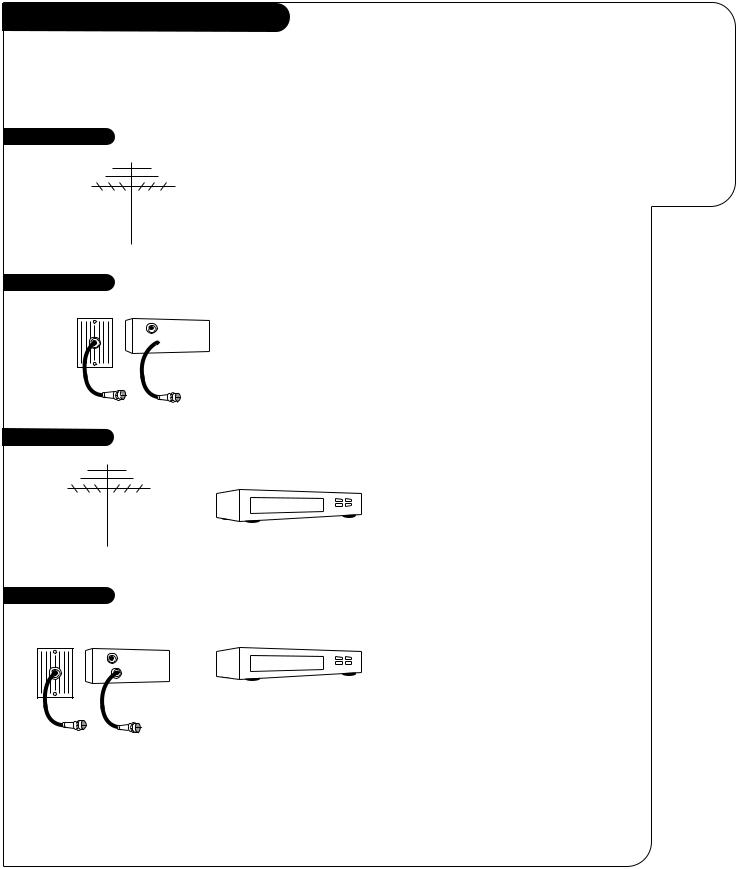
Hook-Up Directory
IMPORTANT
Use this page to decide where you need to begin your setup. First, find the setup option below that best describes what you want to do, then go to that page number.
If you are using an antenna and no other equipment, go to . . . . . . . . . . . . . . . . . . page 4
If you have cable and no other equipment, go to . . . . . . . . . . . . . . . . . . . . . . . . . page 5
Cable TV wall jack
In |
Cable box |
Out 
This page will direct you to which page to go to
for proper hook-up of your
Entertainment Machine.
Antenna with VCR |
If you are using an antenna and have a VCR, go to . . . . . . . . . . . . . . . . . . . . . . . |
page 6 |
Cable and VCR |
If you have cable and a VCR, go to . . . . . . . . . . . . . . . . . . . . . . . . . . . . . . . . . . |
page 7 |
Cable TV |
|
|
wall jack |
|
|
In |
Cable box |
|
Out |
|
|
3373-O
P A G E 4 |
INSTALLATION |
STANDARD |
|
|
|
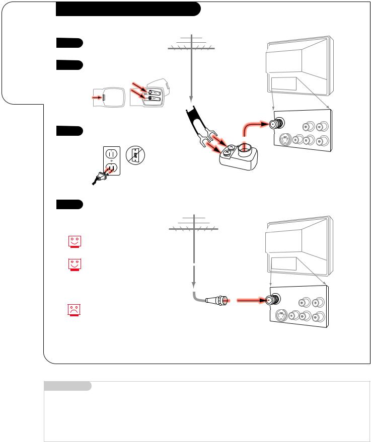
Connect an off-air antenna to your
Entertainment Machine.
Hook Up Your Antenna to the TV
1 |
Hook up your Entertainment |
|
|
|
|
Machine. |
|
|
|
|
|
|
|
|
|
|
|
2 |
Remove the back of the remote |
Antenna |
TV back |
|
|
|
|
|
|||
|
|
|
|
||
and insert two AAA batteries. |
|
|
|
|
|
|
|
|
|
|
|
|
back of |
|
|
|
|
|
remote |
|
|
|
|
|
|
Flat wire |
|
|
|
|
|
(300 ohm) |
Antenna |
Variable |
|
|
|
|
|||
|
|
|
/Cable |
Audio Out |
|
|
|
|
|
R |
L |
3 |
Plug in your TV into a standard |
|
S-Video |
Video |
TV back panel |
120V, 60 Hz power outlet. Do not |
|
(expanded view) |
|||
|
|
|
|||
|
|
|
|
|
|
|
plug it into a switched outlet. |
|
|
R-Audio |
L/Mono |
|
|
|
|
||
|
|
|
300/75 ohm |
|
|
|
|
|
Adapter |
|
|
4 |
Go to page 11 to Auto Program |
your Entertainment Machine. |
If you have a 75 ohm RF cable, then you don’t need any adapters!
Remember, when screwing RF cables into jacks, clockwise tightens, and counterclockwise loosens.
Antenna |
TV back |
A 300 to 75 ohm adapter
is not included with your Zenith Entertainment Machine, but can be purchased in most consumer electronics stores.
RF coaxial wire (75ohm)
Antenna |
Variable |
|
/Cable |
Audio Out |
|
|
R |
L |
S-Video |
Video |
|
|
R-Audio |
L/Mono |
TV back panel (expanded view)
Mini glossary
75 OHM RF CABLE |
The wire that comes from an off-air antenna or cable service provider. Each end looks like a hex shaped nut with a wire |
|
sticking through the middle, and it screws onto the threaded jack on the back of your TV. |
300 TO 75 OHM ADAPTER |
A small device that connects a two-wire 300 ohm antenna to a 75 ohm RF jack. They are usually about an inch long |
|
with two screws on one end and a round opening with a wire sticking out on the other end. |
3373-O
INSTALLATION |
STANDARD |
P A G E 5 |
|
|
|
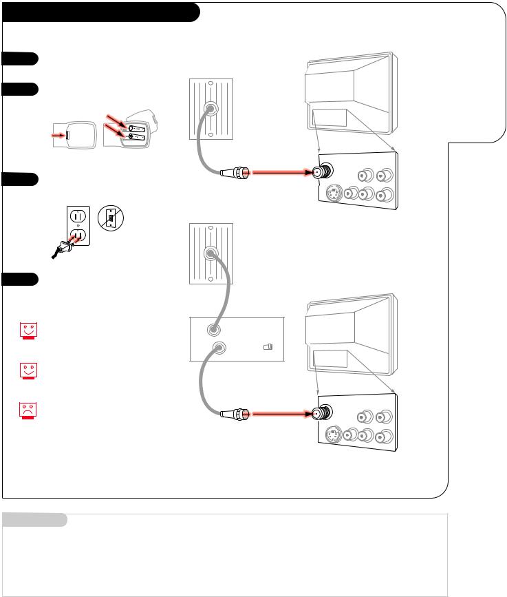
Hook Up Your Cable (CATV) to the TV
1 |
Hook up your Entertainment |
|
Machine. |
||
|
||
2 |
Remove the back of the remote |
|
and insert two AAA batteries. |
||
|
||
|
back of |
|
|
remote |
|
3 |
Plug in your TV into a standard |
|
120V, 60 Hz power outlet. Do not |
||
|
||
|
plug it into a switched outlet. |
4 |
Go to page 11 to Auto Program |
|
your Entertainment Machine. |
||
|
Cable TV wall jack
TV back
|
Antenna |
Variable |
|
|
/Cable |
Audio Out |
|
|
|
R |
L |
RF coaxial wire (75ohm) |
S-Video |
Video |
|
Cable TV |
|
R-Audio |
L/Mono |
|
|
|
|
wall jack
TV back panel (expanded view)
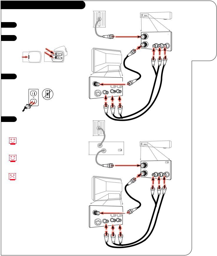
Connect cable to your Entertainment Machine.
If you’re using a cable box, leave your TV on channel 3 or 4 and use your cable box to change channels.
Remember, when screwing RF cables into jacks, clockwise tightens, and counterclockwise loosens.
If you’re using a cable box, Auto Program might only find the channel your cable service is on (usually channel 3 or 4). Don’t worry, that’s all you need!
In |
Cable box |
TV back |
|
|
|||
Out |
output |
|
|
switch |
3 4 |
|
|
|
|
||
|
Antenna |
Variable |
|
|
/Cable |
Audio Out |
|
|
|
R |
L |
RF coaxial wire (75ohm) |
S-Video |
Video |
|
|
|
R-Audio |
L/Mono |
TV back panel (expanded view)
Mini glossary
CABLE SERVICE The wire that supplies all your cable TV (CATV) stations.
3373-O

P A G E 6 |
INSTALLATION |
STANDARD |
|
|
|
Connect an off-air antenna and VCR to your Entertainment Machine.
Hook Up Your Antenna and VCR to TV
Antenna
1 |
Hook up your Entertainment |
Flat wire |
|
VCR back |
|
Machine. |
|
|
|||
|
(300 ohm) |
|
|
|
|
2 |
Remove the back of the remote |
|
|
|
|
and insert two AAA batteries. |
|
VCR back AV panel |
|||
|
|
||||
|
|
300/75 ohm |
In |
output |
|
|
|
switch |
3 4 |
||
|
|
Adapter |
|
Output |
|
|
|
|
Out |
Audio |
Video |
|
back of |
|
L R |
|
|
|
remote |
|
|
|
|
|
|
TV back |
RF coaxial wire |
|
|
|
|
|
|
|
|
3 |
Plug in your TV into a standard |
|
(75ohm) |
|
|
|
not included |
|
|
||
120V, 60 Hz power outlet. Do not |
|
with TV |
|
|
|
|
|
|
|
|
|
|
plug it into a switched outlet. |
|
|
|
|
4 |
Go to page 11 to Auto Program |
|
your Entertainment Machine. |
||
|
Antenna |
|
Variable |
/Cable |
Audio Out |
|
|
||
|
R |
L |
S-Video Video |
|
TV back panel |
|
|
(expanded view) |
R-Audio L/Mono
A/V cables not included with TV
Remember, when screwing
RF cables into jacks, clockwise tightens, and counterclockwise loosens.
No A/V cables are included with your Zenith Entertainment Machine, but can be purchased in most consumer electronics stores.
Without A/V cables, most VCRs will not play videocassettes in stereo sound.
VCR back
Antenna
Round wire (75ohm) |
VCR back AV panel |
|
In |
output |
|
|
switch 3 4 |
|
|
|
|
Output
Out Audio Video
L R
TV back
RF coaxial wire (75ohm)
not included with TV
Antenna |
|
Variable |
|
/Cable |
|
||
Audio Out |
|||
|
|||
|
R |
L |
|
S-Video Video |
TV back panel |
|
(expanded view) |
||
|
R-Audio L/Mono
A/V cables not included
3373-O
Hook Up Your VCR and Cable (CATV)
1 |
Hook up your Entertainment |
|
Machine. |
||
|
||
2 |
Remove the back of the remote |
|
and insert two AAA batteries. |
||
|
||
|
back of |
|
|
remote |
|
3 |
Plug in your TV into a standard |
|
120V, 60 Hz power outlet. Do not |
||
|
||
|
plug it into a switched outlet. |
4 |
Go to page 11 to Auto Program |
|
your Entertainment Machine. |
||
|
Leave your VCR and your television tuned to channel 3 and use the cable box to change channels.
Remember, when screwing in RF cables into jacks, clockwise tightens, and counterclockwise loosens.
No A/V cables are included with your Zenith Entertainment Machine, but can be purchased in most consumer electronics stores. Without A/V cables, most VCRs will not play videocassettes in stereo sound.
INSTALLATION |
STANDARD |
P A G E 7 |
|
|
|
Cable TV wall jack
VCR back
VCR back AV panel Round wire (75ohm) In output 
switch 3 4
Output Out Audio Video
L R
|
TV back |
RF coaxial wire |
|
|
(75ohm) |
|
|
not included |
|
|
with TV |
Antenna |
Variable |
|
/Cable |
Audio Out |
|
S-Video Video |
|
TV back panel |
|
|
(expanded view) |
L/Mono
A/V cables
not included with TV
Cable TV wall jack
In |
|
Cable box |
|
VCR back |
|
|
|
|
|
|
|
||
Out |
output |
|
|
|
|
|
switch 3 4 |
|
|
|
|
||
|
|
|
|
|
||
|
Round wire |
VCR back AV panel |
||||
|
In |
|
output |
|
||
|
|
|
|
switch |
3 4 |
|
|
|
|
|
|
||
|
|
|
|
|
Output |
|
|
|
|
Out |
Audio Video |
||
|
|
|
L |
R |
|
|
|
|
|
|
|
||
|
TV back |
RF coaxial wire |
|
|
|
|
|
|
|
|
|
|
|
|
|
|
(75ohm) |
|
|
|
|
|
|
not included |
|
|
|
|
|
|
with TV |
|
|
|
Antenna |
|
Variable |
|
|
|
|
/Cable |
|
|
|
|
|
|
|
Audio Out |
|
|
|
|
|
|
|
|
|
|
|
|
S-Video |
Video |
|
panel |
|
|
|
|
(expanded view) |
|
|
|
||
|
|
|
|
|
|
|
|
R |
L/Mono |
|
|
|
|
|
|
|
A/V cables |
|
|
|
|
|
|
not included |
|
|
|
|
|
|
with TV |
|
|
|
Connect your VCR and Cable to your Entertainment Machine.
3373-O
P A G E 8 |
INSTALLATION |
CUSTOM |
|
|
|
Connecting an
S-VHS player
to your
Entertainment
Machine.
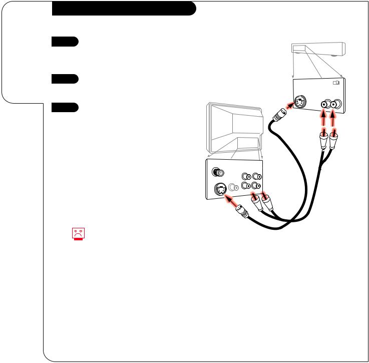
Hook Up Your TV to a Super VHS VCR
1 |
Locate the S-Video Out to TV jack |
|
on the back of your S-VHS VCR. |
||
|
||
|
Connect the S-VHS cable directly |
|
|
to this jack. |
|
2 |
Connect this cable from |
|
the Out to TV jack to the S-Video |
|
jack on the back of your TV. |
|
3 |
Find the audio and S-Video jacks |
|
on the back of your S-VHS player, |
||
|
||
|
and connect them following the |
|
|
instructions provided with your |
|
|
equipment. |
No S-Video cables are included with your Zenith Entertainment Machine, but can be purchased in most consumer electronics stores.. Without an S-Video cable, you will not receive the Super VHS quality picture.
|
VCR back |
|
|
VCR back AV panel |
|
|
output |
|
S-Video cable |
switch 3 |
4 |
S-Video Out Audio Out |
||
not included |
R |
L |
with TV
TV back
Antenna |
|
Variable |
|
/Cable |
|
||
Audio Out |
|||
|
|||
|
R |
L |
|
|
TV back panel |
S-Video Video |
(expanded view) |
|
R-Audio L/Mono |
A/V cables not included with TV
3373-O
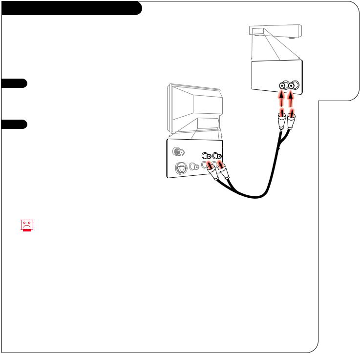
Hook Up Your TV to Stereo Amplifier
For added audio depth and clarity, you can connect your Entertainment Machine to a stereo amplifier!
1 |
Locate the Left/Right Audio |
|
Input jacks on the back of your |
||
|
||
|
stereo amplifier. Connect the |
|
|
Audio cables directly to these |
|
|
jacks. |
|
2 |
Connect these cables from |
the Left/Right Variable Audio Input jacks to the corresponding Left/Right Audio Out jacks on the back of your TV.
No Audio cables are included with your Zenith Entertainment Machine, but can be purchased in most consumer electronics stores.
INSTALLATION |
CUSTOM |
P A G E 9 |
|
|
|
|
Connecting your |
|
Entertainment |
Stereo back |
Machine to a |
|
stereo amplifier. |
Stereo Amplifier back panel
Audio Input
R L
TV back
Antenna |
|
|
TV back panel |
|
|
Variable |
(expanded view) |
||
/Cable |
|
|||
Audio Out |
||||
|
|
|||
|
R |
L |
|
|
S-Video |
Video |
|
|
|
|
R- |
|
|
|
A/V cables not included with TV
3373-O
P A G E 1 0 |
OPERATION |
BUTTON FUNCTIONS |
|
|
|
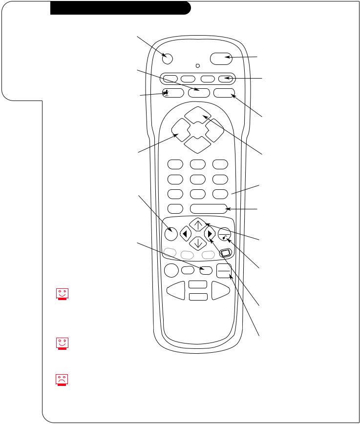
A quick list of all the buttons on your remote and what they do.
Remote Control Button Functions
PRG(PROGRAM) |
|
|
|
|
|
Used to begin |
|
|
|
|
|
programming procedure. |
|
|
|
|
|
|
PRG |
|
|
POWER |
|
FLASHBK(FLASHBACK) |
|
|
|
|
|
Return to the last |
CABLE VCR |
AUX |
TV |
||
channel viewed. |
|||||
|
|
|
|
||
SURF |
SURF |
FLASHBK |
MUTE |
||
Activates custom channel select |
|
|
|
|
|
mode on your Entertainment |
|
CHANNEL |
|
||
Machine. When Surf mode is |
|
|
|||
active, CHANNEL UP/DOWN keys |
|
|
|
|
|
”Surf” through the channels |
VOLUME |
|
VOLUME |
||
you’ve selected. |
|
|
|
|
|
|
|
CHANNEL |
|
||
POWER
Turns TV On and Off.
(MODES)
CABLE/VCR/AUX/TV
Selects mode of operation for Remote Control
MUTE
Turns sound down (Soft) or off (Mute) while the picture remains.
VOLUME (LEFT/RIGHT ARROWS)
Adjusts the sound level on your Entertainment Machine.
MENU
Displays on-screen menus. Press repeatedly to cycle through other menus.
TIMER
Displays the Sleep Timer Menu. See page 21 for more information.
If your remote has Night Vision Glow-In-The-Dark keys, it must be exposed to light before the keys will glow in the dark. Longer exposure—longer glow.
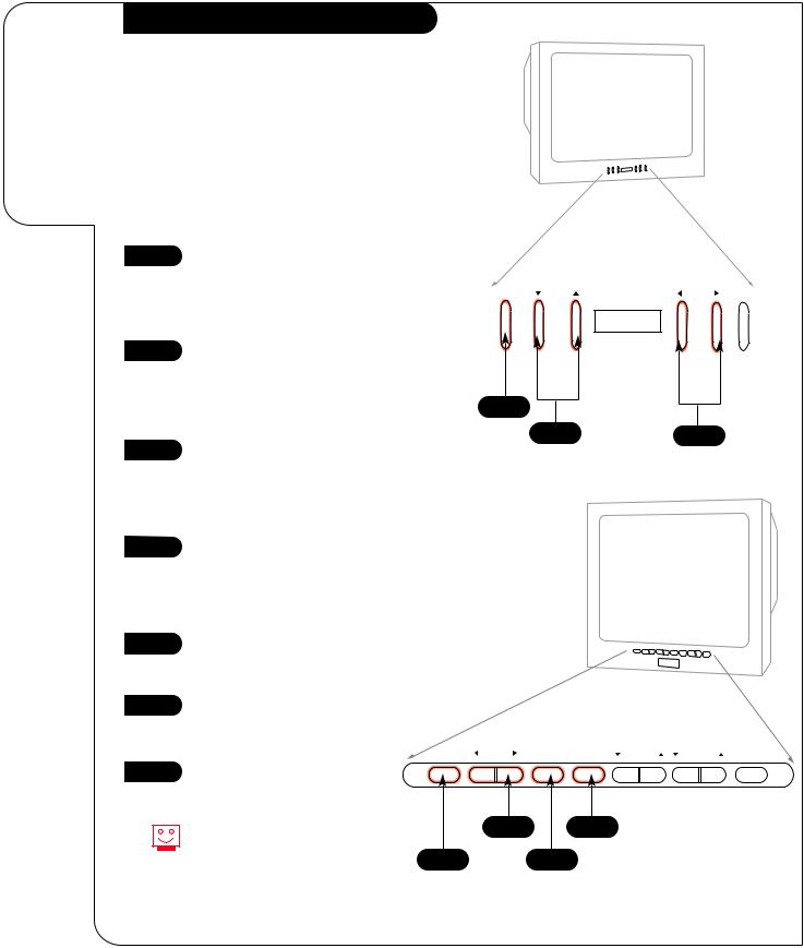
Keys dedicated to VCR functions will still operate your VCR while the remote is in TV mode.
Grey keys indicate that they do not function on your model of TV.
CHANNEL (UP/DOWN)
1 2 3 Cycles through available channels.
4 5 6
NUMBER KEY PAD
7 8 9  Key-in numbers for direct channel tuning.
0 |
|
ENTER |
||
MENU |
|
|
QUIT |
|
|
|
|
||
A |
B |
C |
CC |
|
|
||||
|
|
|||
RECORD PAUSE |
TIMER |
TV/VCR |
||
SOURCE |
||||
|
|
|
||
|
|
PLAY |
|
|
REWIND |
|
|
FFWD |
|
|
|
STOP |
|
|
ENTER
Shows the Channel/Time display. Press after channel numbers for instant selection.
UP/DOWN ARROW
The UP/DOWN arrows select options.
QUIT/
Escape from most Menu options and toggle between Audio features.
remote control part number
MBR3447
LEFT/RIGHT ARROW
The LEFT/RIGHT arrows adjust options.
TV/VCR SOURCE
Switches between watching TV via the available sources, that is ANTENNA/CABLE and VIDEO IN.
3373-O
OPERATION
Auto Program
1
2
3
4
5
6
7
With the remote control in hand, |
1 |
|
press the POWER key to turn on |
||
|
||
your Entertainment Machine. |
|
|
Press the MENU key so the Setup |
|
|
menu appears. |
|
|
Using the UP/DOWN arrows on |
|
|
the remote control, select Auto |
|
|
Program on your screen. (The first |
|
|
selection at the top.) |
|
|
Press a RIGHT or LEFT arrow to |
|
|
reach the Auto Program screen. |
|
|
Using the UP/DOWN arrows, |
|
|
choose either Cable TV or Off-Air |
|
|
Antenna on your screen. |
|
|
Press a RIGHT or LEFT arrow to |
|
|
begin Auto Program. |
|
|
TV viewing. |
|
CABLE |
VCR |
AUX |
TV |
SURF |
FLASHBK |
MUTE |
|
CHANNEL
VOLUME VOLUME
CHANNEL
1 2 3
4 5 6
7 8 9
A |
B |
C |
CC |
|
|||
|
|
RECORD PAUSE TIMER
TV/VCR
SOURCE
|
PLAY |
REWIND |
FFWD |
|
STOP |
AUTO PROGRAM P A G E 1 1
Select your input source, then automatically find and store all the stations available in your area.
7
3/5
4/6
Mini glossary
AUTO PROGRAM Auto Program is how your Entertainment Machine finds all the channels available in your area and stores them into memory.
3373-O
P A G E 1 2 |
OPERATION |
FRONT PANEL CONTROLS |
|
|
|
An example of using the panel on the front of your Entertainment Machine.
Front Panel Diagram
The front keypads on your Entertainment Machine vary from model to model. Examine the front panel and follow the directions which apply to your machine.
When using the on-screen menus, the buttons on the front keypad correspond to the buttons on the remote control as follows:
VOLUME = Adjust Left/Right
CHANNEL = Select Up/Down
1
2
3
To access the on-screen menus, push the MENU button on the panel. Cycle through the various menus by pushing the button repeatedly.
Choose the function you wish to change using the CHANNEL UP/DOWN buttons. The Channel buttons act as a “Select”
The VOLUME buttons “adjustment” (Left/Right) function. Use the VOLUME buttons to make changes or adjustments.
menu |
channel |
power |
1
3
1 |
To access the on-screen menus, |
|
|
|
|
push the MENU button on the |
|
|
|
|
|
|
|
|
|
|
|
|
panel. Cycle through the various |
|
|
|
|
|
menus by pushing the MENU but- |
|
|
|
|
|
ton repeatedly. |
|
|
|
|
2 |
Press the SELECT button |
|
|
|
|
repeatedly to highlight the option |
|
|
|
|
|
|
|
|
|
|
|
|
you want to modify. |
|
|
|
|
3 |
Press either Right or Left on the |
|
|
|
|
ADJUST button to modify the |
|
|
|
|
|
|
|
|
|
|
|
|
option you have chosen. |
|
|
|
|
|
ENTER |
ADJUST |
SELECT MENU |
VOLUME |
CHANNEL OFF-ON |
4 |
Push the ENTER button to return |
|
|
|
|
to normal TV viewing. |
|
|
|
|
|
|
|
|
|
|
|
|
Menus disappear after five seconds. |
3 |
1 |
|
|
|
To get them back, push the MENU |
|
|
|
|
4 2
3373-O
OPERATION |
TV FUNDAMENTALS |
P A G E 1 3 |
|
|
|
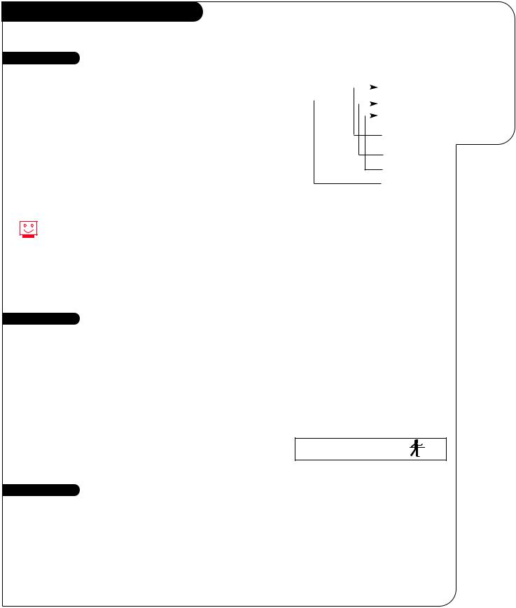
Basic Television Operation
Source
The source button (TV/VCR/Source) on the remote switches between Video input and Cable/Antenna input. On some models A/V input is designated as a channel that is one below the lowest/one above the highest.
You’ll have to use the Channel Up/Down buttons to access it. The Time/Channel display will read “Video” in place of a channel number.
Cable/Antenna Input: This setting allows you to change cable or
antenna channels and to view videocassettes on channel 3 (or 4) in mono sound.
Video Input: This setting allows stereo playback of videocassettes. The television cannot change channels in the Video mode, but the VCR can.
To view the current input source, press ENTER on your remote. The Time/Channel display should appear in the upper right-hand corner of the screen. If the display reads ‘Video,’ then the source is an A/V input. If the display reads a channel number, then the source is your Cable or Antenna.
Introducing you to the basics of your Entertainment Machine.
DEC/11/98 |
|
|
|
|
|
|
CH 12-FOX |
||
|
|
|
|||||||
|
|
|
|
|
|
|
|
|
10:55 |
|
|
|
|
|
|
|
|
|
|
|
|
|
|
|
|
|
|
|
|
|
|
|
|
|
|
|
|
|
|
|
|
|
|
|
|
|
|
|
STEREO |
|
|
|
|
|
|
|
|
|
|
|
|
|
|
|
|
|
|
|
|
Channel or Video (Indicates Source)
Time
Audio Mode
Date
This is an example of the Time/Channel display that appears in the top right and left corners of your screen.
Channel Changing
CHANNEL UP/DOWN arrows: Use these arrows to change the channels. Auto Program will have found all channels available to you.
NUMBER Key Pad: To skip to any channel, enter the number of the channel using the NUMBER key pad, then press ENTER.
FLASHBACK: To instantly return to the last channel viewed, press FLASHBACK.
SURF: Switches between the primary channel selection and your customized surf menus. The surf mode will appear in the lower right corner of your screen.
Audio
SURF 1
Volume Right/Left: To adjust the volume level, use the volume Right/Left arrows. To soften the volume of your TV, press MUTE once. To silence your TV instantly, press MUTE twice. To get the sound back, press MUTE again.
3373-O
 Loading...