


SAFETY PRECAUTIONS
SERVICE WARNING
Only qualified service technicians who are familiar with safety checks and guidelines should perform service work. Before replacing parts, disconnect power source to protect electrostatically sensitive parts. Do not attempt to modify any circuit unless so recommended by the manufacturer. When servicing the receiver, use an isolation transformer between the line cord and power receptacle.
SERVICING THE HIGH VOLTAGE AND CRT
Use EXTREME CAUTION when servicing the high voltage circuits. To discharge static high voltage, connect a 10K ohms resistor in series with a test lead between the receiver ground and CRT anode lead. DO NOT lift the CRT by the neck. Always wear shatterproof goggles when handling the CRT to protect eyes in case of implosion.
X-RAY RADIATION AND HIGH VOLTAGE LIMITS
Be aware of the instructions and procedures covering X-ray radiation. In solid-state receivers and monitors, the CRT is the only potential source of X-rays. Keep an accurate high voltage meter available at all times. Check meter calibration periodically. Whenever servicing a receiver, check the high voltage at various brightness levels to be sure it is regulating properly. Keep high voltage at rated value, NO HIGHER. Excessive high voltage may cause X-ray radiation or failure of associated components. DO NOT depend on protection circuits to keep voltage at rated value. When troubleshooting a receiver with excessive high voltage, avoid close contact with the CRT. DO NOT operate the receiver longer than necessary. To locate the cause of excessive high voltage, use a variable AC transformer to regulate voltage. In present receivers, many electrical and mechanical components have safety related characteristics which are not detectable by visual inspection. Such components are identified by a
# on both the schematic and the parts list. For SAFETY, use only equivalent replacement parts when replacing these components.
GENERAL GUIDELINES
Perform a final SAFETY CHECK before returning receiver to customer. Check repaired area for poorly soldered connections, and check entire circuit board for solder splashes. Check board wiring for pinched wires or wires contacting any high wattage resistors. Check that all control knobs, shields, covers, grounds, and mounting hardware have been replaced. Be sure to replace all insulators and restore proper lead dress.
SAFETY CHECKS — FIRE AND SHOCK HAZARD
Cold Leakage Checks for Receivers with Isolated Ground
Unplug the AC cord, connect a jumper across the plug prongs, and turn the power switch on (if applicable). Use an ohmmeter to measure the resistance between the jumped AC plug and any exposed metal cabinet parts such as antenna screw heads, control shafts, or handle brackets. Exposed metal parts with a return path should measure between 1M ohms and 5.2M ohms. Parts without a return path must measure infinity.
Hot Leakage Current Check
Plug the AC cord directly into an AC outlet. DO NOT use an isolation transformer. Use a 1500 ohms, 10W resistor in parallel with a .15µF capacitor to connect between any exposed metal parts on the receiver and a good earth ground. (See figure below.) Use an AC voltmeter with at least 5000 ohms per volt sensitivity to measure the voltage across the resistor. Check all exposed metal parts and measure voltage at each point. Voltage measurements should not exceed .75VAC, 500µA. Any value exceeding this limit constitutes a potential shock hazard and must be corrected. If the AC plug is not polarized, reverse the AC plug and repeat exposed metal part voltage measurement at each point.
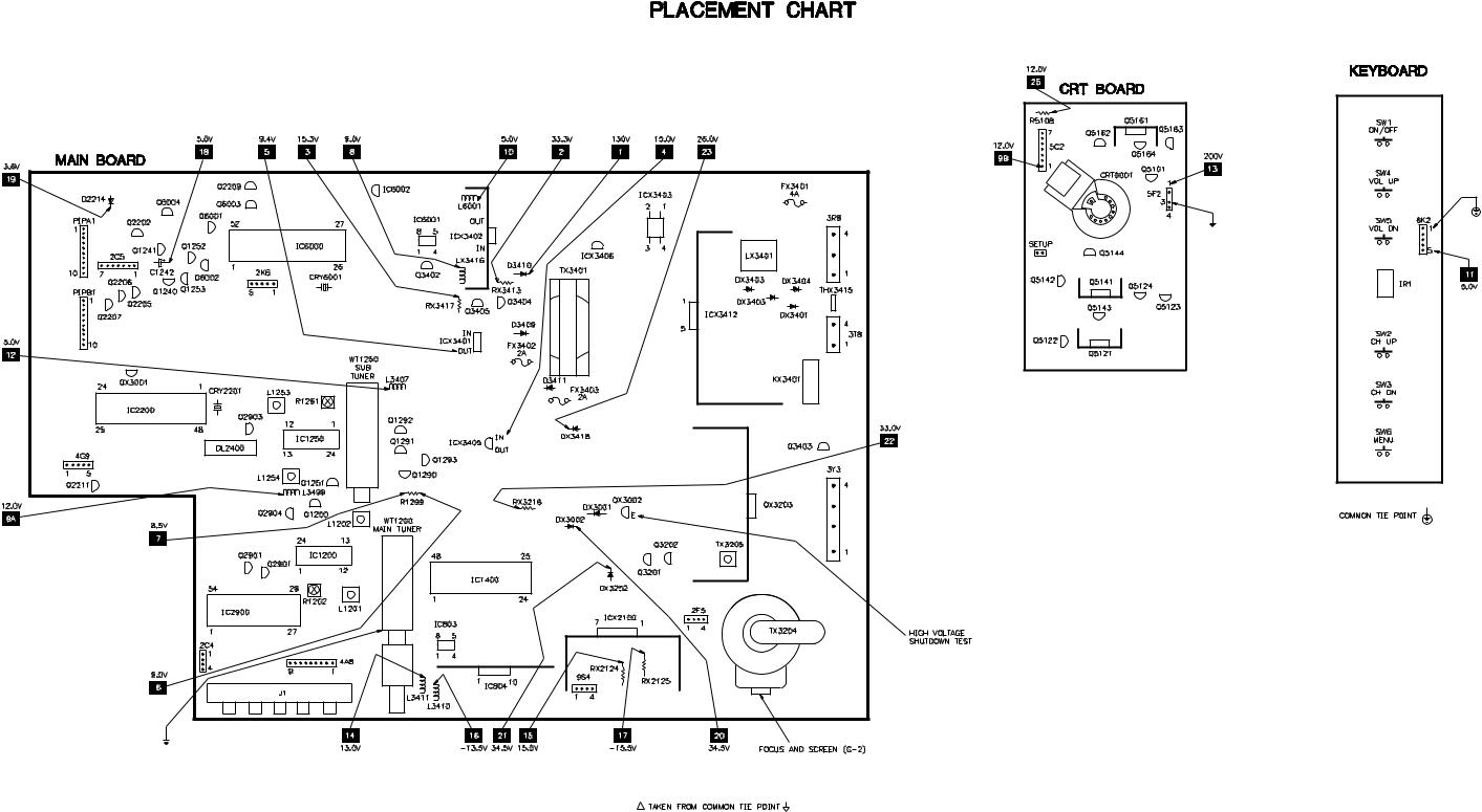
HIGH VOLTAGE SHUTDOWN TEST
Turn receiver on, adjust customer controls for normal operation. Temporarily apply an external bias of 14.0V to the emitter of QX3002. The receiver should lose raster. If the receiver does not lose raster the shutdown circuit should be repaired. Remove AC power, wait 30 seconds and test for normal operation.
The listing of any available replacement part herein in no case constitutes a recommendation, warranty, or guarantee by SAMS Technical Publishing as to the quality and suitability of such replacement part. The numbers of the listed parts have been compiled from information furnished to SAMS Technical Publishing by the manufacturers of the specific type of replacement part listed.
Reproduction or use, without express permission, of editorial or pictorial content, in any manner, is prohibited. No patent liability is assumed with respect to the use of the information contained herein.
© 2003
|
|
|
UPC |
5436 West 78th |
Street |
|
HERE |
Indianapolis, IN |
46268-4149 |
|
|
Printed in the United States of America 5 4 3 2 1 |
03PF02083 |
|
|
Page 1 SET 4703 |
|
|
|
|
|
||
SET 4703
MODEL B27B40Z
4703
ZENITH
INDEX |
|
High Voltage Shutdown Test .................. |
1 |
IC Functions ........................................... |
4 |
Important Parts Information ................... |
3 |
Miscellaneous Adjustments .................... |
1 |
Parts List ................................................. |
4 |
Placement Chart ..................................... |
1 |
Safety Precautions .................................. |
1 |
Schematic Component Location ............ |
3 |
Schematic Notes ..................................... |
3 |
Schematics |
|
A/V .................................................. |
3 |
Audio ............................................... |
2 |
PIP IF .............................................. |
3 |
Power Supply .................................. |
2 |
System Control ................................ |
3 |
Television ........................................ |
2 |
Service Mode Adjustment Chart ............ |
1 |
Test Equipment ....................................... |
3 |
Tuner Information .................................. |
1 |
For Supplier Address,
See PHOTOFACT Annual Index
4703
Technical Service Data
ZENITH
Model B27B40Z
Representative Model
Essential coverage
for servicing a television receiver...
•Schematics
•Component locations
•Parts list
4703
MARCH 2003 SET 4703
Page 1 SET 4703
TUNER INFORMATION
|
|
MAIN TUNER VOLTAGE CHART |
|
|
Pin |
VHF Low Band |
VHF High Band |
UHF Band |
|
(1) AGC |
2.2V |
2.0V |
1.7V |
|
(2) TU |
1.2V |
4.1V |
6.0V |
|
(3) |
EN/AS |
1.2V |
1.2V |
1.2V |
(4) |
CLK |
4.8V |
4.8V |
4.8V |
(5) |
DATA |
4.8V |
4.8V |
4.8V |
(6) |
9V |
0V |
0V |
0V |
(7) |
5V |
5.0V |
5.0V |
5.0V |
(8) LOCK |
0V |
0V |
0V |
|
(9) |
33V |
33.5V |
33.5V |
33.5V |
(10) IF2 |
0V |
0V |
0V |
|
(11) IF OUT |
0V |
0V |
0V |
|
NOTE: |
VHF Low Band voltages taken on channel 2. |
|
||
|
|
VHF High Band voltages taken on channel 7. |
|
|
|
|
UHF Band voltages taken on channel 14 |
|
|
|
|
SUB TUNER VOLTAGE CHART |
|
|
Pin |
VHF Low Band |
VHF High Band |
UHF Band |
|
(1) AGC |
2.3V |
2.1V |
1.8V |
|
(2) TU |
1.2V |
4.0V |
6.0V |
|
(3) |
EN/AS |
1.2V |
1.2V |
1.2V |
(4) |
CLK |
4.8V |
4.8V |
4.8V |
(5) |
DATA |
4.8V |
4.8V |
4.8V |
(6) |
9V |
0V |
0V |
0V |
(7) |
5V |
5.0V |
5.0V |
5.0V |
(8) LOCK |
0V |
0V |
0V |
|
(9) |
33V |
33.3V |
33.3V |
33.3V |
(10) IF2 |
0V |
0V |
0V |
|
(11) IF OUT |
0V |
0V |
0V |
|
NOTE: VHF Low Band voltages taken on channel 2.
VHF High Band voltages taken on channel 7.
UHF Band voltages taken on channel 14
MAIN TUNER TERMINAL GUIDE
|
τ |
(1) |
(2) |
τ |
|
|
|
|
|
τ |
(3) |
(4) |
τ |
|
|
|
|
|
τ |
(5) |
(6) |
τ |
|
|
|
|
|
τ |
(7) |
(8) |
τ |
|
|
|
|
|
τ |
(9) |
(10) |
τ |
|
|
|
|
|
τ |
(11) |
SUB TUNER TERMINAL GUIDE
|
τ |
(1) |
(2) |
τ |
|
|
|
|
|
τ |
(3) |
(4) |
τ |
|
|
|
|
|
τ |
(5) |
(6) |
τ |
|
|
|
|
|
τ |
(7) |
(8) |
τ |
|
|
|
|
|
τ |
(9) |
(10) |
τ |
|
|
|
|
|
τ |
(11) |
MISCELLANEOUS ADJUSTMENTS
This receiver employs digital customer controls which are accessed through the service menu. All adjustments were performed at reset unless otherwise indicated. Record all the data values for all functions in the service menu before making any changes.
HIGH VOLTAGE CHECK
Tune in a picture. Set brightness and color to minimum. Connect a high voltage probe to CRT anode. High voltage should read from 27kV to 29kV.
SERVICE MENU
To access the service menu adjustments by using the remote transmitter keypad, press and hold the menu button until the menu display disappears from the screen. Key in 9, 8, 7, 6, and press the enter button.
To access the service menu adjustments by using the receiver keypad, press the menu button until the display disappears from the screen. Without releasing the menu button simultaneously press the adjust right and channel up buttons.
The receiver is now in service menu mode with function 03 H Pos 16 displayed. The first line on the service menu is a version number of the software used in the receiver. On the bottom is a date the module went through the factory. Use the select up and down buttons to select function. Use the adjust buttons to make changes to selected function. The function 00 F Mode (Factory Mode) is always set to 0. Only the first seven items in the service menu can be brought up. Use the select key to select the 00 F Mode function and change the adjustment to 1, now all the menu items will be accessible.
NOTE: Set value of function 00 F Mode (Factory Mode) to 0 before exiting the service menu mode. If not set to 0 the receiver will not shut off with the remote or power button on the receiver.
HORIZONTAL SIZE
Tune in a crosshatch pattern. Call up service menu, select function 11, set data value for slight overscan on both sides.
RF AGC
Tune in a picture. Adjust R1202 to a point where snow appears in picture, then to a point where snow disappears.
COLOR TEMPERATURE
Tune in a crosshatch pattern. Set brightness, picture, and color to minimum. Call up service menu, select functions 27, 28, and 29, set data values to 0. Adjust data values for functions 30, 31, and 32 of the two least predominate colors to obtain a white pattern. Tune in an active black and white channel and adjust functions 27, 28, and 29 for best white to black tracking at high and low brightness.
COLOR PURITY / CONVERGENCE
CRT and yoke are bonded. Color purity and convergence adjustments are not recommended.
SET 4703 Page 1
SERVICE MODE ADJUSTMENT CHART
FUNCTION |
DATA |
ON-SET |
VALUE |
|
FUNCTION |
DATA |
ON-SET |
VALUE |
|
||||
221-01389 |
VALUE |
VALUE |
RANGE |
NOTES |
221-01389 |
VALUE |
VALUE |
RANGE |
NOTES |
||||
00 |
F Mode |
0 |
0 |
0 |
- 1 |
Factory Mode. Normal setting is 0, when set to 1, all other functions are accessible. |
47 |
PIP X1 |
17 |
20 |
0 |
- 254 |
Horizontal position on left side. |
01 |
Pre Px |
0 |
1 |
0 |
- 1 |
Stores customer video menu picture preference (P RESET). 0 is custom, |
48 |
PIP Y1 |
25 |
23 |
0 |
- 254 |
Vertical position on left side. |
|
|
|
|
|
|
1 is preset stored. |
49 |
PIP X2 |
113 |
117 |
0 |
- 254 |
Horizontal position on right side. |
02 V Pos |
15 |
16 |
0 |
- 30 |
Vertical position of On Screen Displays (Menus & Captions). |
50 |
PIP Y2 |
143 |
151 |
0 |
- 254 |
Vertical position on right side. |
|
03 |
H Pos |
42 |
42 |
0 |
- 80 |
Horizontal position of On Screen Displays (Menus & Captions). |
51 |
PIP Adj |
2 |
3 |
0 |
- 15 |
Picture In Picture Adjustment. |
04 |
Level |
1 |
1 |
0 |
- 2 |
- |
52 |
PIP Y DL |
4 |
1 |
0 |
- 15 |
Picture In Picture Y Delay. |
05 |
Band |
0 |
0 |
0 |
- 7 |
This setting depends upon input signal. 0 Broadcast Fixed, 1 CATV AFC, |
53 |
PIP Y Off |
31 |
31 |
0 |
- 31 |
Picture In Picture Y Offset. |
|
|
|
|
|
|
3 ICC AFC, 4 Broad cast AFC, 5 CATV F ixed, 6 HRC Fixed, 7 ICC Fixed. |
54 PIP ACC |
20 |
20 |
0 |
- 63 |
Picture In Picture ACC Level. |
|
06 AC On |
0 |
0 |
0 |
- 1 |
Enables AC Power On feature. |
55 |
P BGST |
10 |
10 |
0 |
- 63 |
Picture In Picture BG Stat Level. |
|
07 |
RF Brt |
15 |
14 |
0 |
- 31 |
RF Brightness. |
56 |
PIP HX |
22 |
25 |
0 |
- 63 |
Picture In Picture HX. |
08 Ax Brt |
15 |
14 |
0 |
- 31 |
Auxiliary Brightness. |
57 |
PIP VXS |
37 |
38 |
0 |
- 63 |
Picture In Picture VXS. |
|
09 |
Max Con |
63 |
35 |
0 |
- 63 |
Maximum Contrast. |
58 |
PIP R Con |
50 |
14 |
0 |
- 63 |
Picture In Picture Red Contrast. |
10 V Size |
38 |
24 |
0 |
- 63 |
Vertical Size. |
59 |
PIP G Con |
50 |
15 |
0 |
- 63 |
Picture In Picture Green Contrast. |
|
11 |
H Size |
63 |
31 |
0 |
- 63 |
Horizontal Size. |
60 |
PIP B Con |
50 |
17 |
0 |
- 63 |
Picture In Picture Blue Contrast. |
12 V Phase |
42 |
46 |
0 |
- 63 |
Vertical Phase. |
61 |
PIP Comp |
2 |
2 |
0 |
- 3 |
Picture In Picture Comp. |
|
13 |
H Phase |
0 |
13 |
0 |
- 63 |
Horizontal Phase. |
62 YUV Brt |
10 |
0 |
0 |
- 31 |
YUV Sub-Brightness. |
|
14 |
H Osc |
7 |
9 |
0 |
- 31 |
Horizontal Osc. |
63 |
Min Con |
10 |
25 |
0 |
- 31 |
Minimum Contrast Value. |
15 |
S Corr |
7 |
7 |
0 |
- 31 |
S Correction. |
64 |
F Jacks |
1 |
1 |
0 |
- 1 |
Front Jacks. |
16 V Linea |
7 |
7 |
0 |
- 15 |
Vertical Linearity. |
65 |
PIP Brt |
200 |
201 |
0 |
- 254 |
Picture In Picture Brightness. |
|
17 Pin Amp |
63 |
23 |
0 |
- 63 |
Pin Amp. |
66 |
Xtal |
0 |
0 |
0 |
- 1 |
Select Crystal or RC circuit Oscillator for OSD. |
|
18 |
C Pin |
63 |
30 |
0 |
- 63 |
Corner Pin. |
67 |
Min Brt |
25 |
25 |
0 |
- 63 |
Custom Minimum Brightness. |
19 Trapez |
15 |
7 |
0 |
- 15 |
Trapezium. |
68 |
Max Brt |
35 |
35 |
0 |
- 63 |
Custom Maximum Brightness. |
|
20 |
EHT Com |
7 |
15 |
0 |
- 15 |
EHT Comp. |
69 |
GM PIP X |
15 |
15 |
0 |
- 50 |
PIP X position for gemstar. |
21 AFC Bow |
7 |
7 |
0 |
- 15 |
AFC Bow. |
70 |
GM PIP Y |
17 |
17 |
0 |
- 30 |
PIP Y position for gemstar. |
|
22 AFC Ang |
7 |
7 |
0 |
- 15 |
AFC Angle. |
71 |
GM Pos X |
36 |
36 |
0 |
- 60 |
OSD X position for gemstar. |
|
23 |
Up V Lin |
6 |
6 |
0 |
- 15 |
Upper Vertical Linearity. |
72 |
GM Pos Y |
13 |
13 |
0 |
- 36 |
OSD Y position for gemstar. |
24 |
Lo V Lin |
0 |
0 |
0 |
- 15 |
Lower Vertical Linearity. |
73 |
GM Siz X |
110 |
110 |
0 |
- 152 |
OSD X Size for gemstar. |
25 AFC G |
1 |
0 |
0 |
- 3 |
AFC Gain. |
74 |
GM Siz Y |
100 |
100 |
0 |
- 233 |
OSD Y Size for gemstar. |
|
26 |
EWDC |
1 |
0 |
0 |
- 1 |
EWDC. |
75 |
Mut Brt |
20 |
20 |
0 |
- 63 |
Level Brightness when mute. |
27 |
R Cut |
0 |
8 |
0 |
- 15 |
Red Cutoff. |
76 |
Mut Con |
20 |
20 |
0 |
- 63 |
Level Contrast when mute. |
28 |
G Cut |
0 |
1 |
0 |
- 15 |
Green Cutoff. |
77 |
GMVSize |
30 |
30 |
0 |
- 63 |
GMVSize. |
29 |
B Cut |
0 |
0 |
0 |
- 15 |
Blue Cutoff. |
|
|
|
|
|
|
|
30 |
R Gain |
31 |
48 |
0 |
- 63 |
Red Gain. |
|
|
|
|
|
|
|
31 |
G Gain |
31 |
35 |
0 |
- 63 |
Green Gain. |
|
|
|
|
|
|
|
32 |
B Gain |
31 |
30 |
0 |
- 63 |
Blue Gain. |
|
|
|
|
|
|
|
33 |
Dynam C |
0 |
0 |
0 |
- 1 |
Dynamic C Video. |
|
|
|
|
|
|
|
34 Gamma |
0 |
0 |
0 |
- 3 |
Gamma Register. |
|
|
|
|
|
|
|
|
35 |
DCTran |
1 |
1 |
0 |
- 1 |
DCTran Video. |
|
|
|
|
|
|
|
36 |
C Bpf |
1 |
0 |
0 |
- 1 |
C Bpf Video. |
|
|
|
|
|
|
|
37 |
C Trap |
1 |
1 |
0 |
- 1 |
C Trap Off Video. |
|
|
|
|
|
|
|
38 |
FSC Sw |
0 |
0 |
0 |
- 1 |
FSC Sw Video. |
|
|
|
|
|
|
|
39 ABL Mode |
1 |
1 |
0 |
- 1 |
ABL Mode Video. |
|
|
|
|
|
|
|
|
40 ABLVTH |
1 |
1 |
0 |
- 1 |
ABLVTH Video. |
|
|
|
|
|
|
|
|
41 |
6 Keys |
1 |
1 |
0 |
- 1 |
Set to 0 for the 10 key keyboard, set to 1 for the 6 key keyboard. |
|
|
|
|
|
|
|
42 A Att |
9 |
7 |
0 |
- 15 |
Audio Input Attenuator. |
|
|
|
|
|
|
|
|
43 A VCO |
31 |
31 |
0 |
- 63 |
Audio Voltage Controlled Oscillator. |
|
|
|
|
|
|
|
|
44 A Filter |
31 |
27 |
0 |
- 63 |
Audio Filter. |
|
|
|
|
|
|
|
|
45 ASpectral |
31 |
12 |
0 |
- 63 |
High Frequency Separation. |
|
|
|
|
|
|
|
|
46 W Band |
31 |
31 |
0 |
- 63 |
Low Frequency Separation. |
|
|
|
|
|
|
|
|
ZENITH
B27B40Z MODEL
SET 4703 Page 1

Page 2 SET 4703
 Loading...