

yaskawa MX2 Maintenance Manual
m
lYASKAWA
J*kl?ECTRIG
TOE-C843-8
’
INSTRUCTIONS
35
A
@C3S
:
.
(H2IS
CJatSSXIIxIK®
•
wnMmmzmsi
.
m
.
i
':
@U301MSÿ5
’v'
Mr
read
V
thoroughly,
tor
future
8e/o'e
initial
these
reference
operation
instructions
and
retain
Jk
A
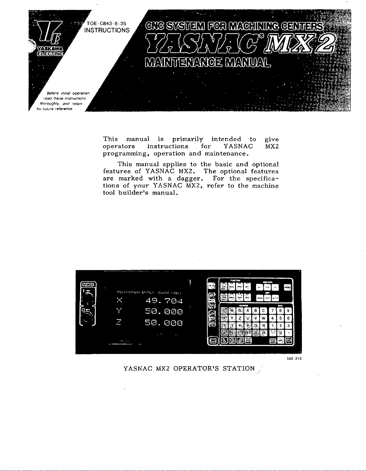
This
operators
programming,
features
are
tions
tool
manual
This
marked
your
of
builder's
instructions
manual
YASNAC
of
is
operation
applies
with
YASNAC
manual.
primarily
MX2.
a
dagger.
and
to
MX2,
intended
for
maintenance.
the
The
For
refer
YASNAC
basic
optional
to
the
and
specifica¬
the
to
give
MX2
optional
features
machine
KlSi,
]&%
—MB
-Ggaa
b«-
T
z>;
•
cus
>:AL,
:
-£s
00000
>
49.
50.
50.
foot:
704
000
000
OPERATOR'S
MX2
M
a
H
m
r
©
IT
a?
ail
STATION
*5*
P
1
A
U,
9
8
7
B
c
V
w
5
6
4
1.
3
2
R;
9.
0
-
F-
K'
H
582-216
t
i
r
T
X
V
z
YASNAC


TABLE
OF
CONTENTS
GENERAL
1.
COMPONENT
1.1
YASNAC
BLOCK
1.2
CONTROL
MAINTENANCE
1.3
ROUTINE
1.4
Tape
1.4.1
Control
1.4.2
Servomotor
1.4.3
Battery
1.4.4
TROUBLESHOOTING
2.
TROUBLE
2.1
Nature
2.1.1
Operations
2.1.2
NC
2.1.3
TROUBLESHOOTING
2.2
List
2.2.1
Counteracting
2.2.2
TROUBLESHOOTING
2.3
CODES
2.4
ACGC
ACGC
2.4.1
ACGC
2.4.2
Faults
2.4.3
Indication
Software
2.4.4
1
CONTROL
DIAGRAM
SYSTEM
INSPECTION
Reader
Panel
ISOLATION
and
Unit
of
Alarm
31
MAINTENANCE
Trouble
Alarm
not
39
ARRANGEMENT
SYSTEM
OF
4
INSTRUMENTS
6
6
and
7
Check
DC
Circumstances
and
Programming
9
Codes
Alarms
Service
Indication
Displayed
Version
Indication
1
YASNAC
SCHEDULE
Motor
8
8
ALARM
BY
11
22
WITHOUT
38
Activity
38
ACGC
by
OF
for
of
5
Spindle
Trouble
Checks
CODES
ALARM
38
Alarm
40
SUPPLY
2.5
2.5.1
Input
DC
2.5.2
STATUS
2.6
DIAGNOSTICS
Outline
2.6.1
Operating
5
6
8
8
10
2.6.2
Input
/Output
2.6.3
List
ADJUSTMENTS
3.
ADJUSTMENT
3.1
POWER
3.2
3.2.1
Tap
(IT)
DISPLAYING
3.3
3,3.1
Parameter
3.3.2
Parameter
3.3.3
Parameter
3.3.4
Tape
Data
3.3.5
Punching-Out
Parameter
3.3.6
Setting
Parameter
3.3.7
APPENDIX
VOLTAGE
Power
Power
of
TRANSFORMER
Changing
54
Input
56
Data
STORED
Supply
DISPLAY
FUNCTION
Displays
Procedure
Signals
Standard
Types
Data
Data
Numbers
Numbers
COMPENSATION
CHECK
Supply
Voltage
BY
42
42
Input/Output
UPON
PROCEDURES
AND
INSTALLATION
Control
on
WRITING
55
Display
Writing
of
Setting
Setting
of
56
and
LEADSCREW
83
40
Voltage
Check
Check
ON-LINE
<DCN)
to
42
Display
52
CONNECTIONS
Transformer
PARAMETERS
55
55
and
Data
and
Data
Their
Contents
and
Their
Contents
ERROR
41
Signals
52
Parameter
40
43
54
55
57
59
-binSb-
i

INDEX
Subject
ACGC
A
ACGC
ACGC
ADJUSTMENT
ADJUSTMENTS
APPENDIX
COMPENSATION
Battery
B
BLOCK
C
COMPONENT
SYSTEM
Control
Counteracting
D
F
G
I
L
Power
DC
DISPLAYING
Faults
Indication
GENERAL
Input
of
List
List
of
Alarm
MAINTENANCE
Trouble
not
Power
Indication
Service
PROCEDURES
STORED
DIAGRAM
ARRANGEMENT
Panel
Alarm
Standard
Alarms
Supply
AND
Displayed
Supply
Codes
UPON
Input/Output
Activity
INSTALLATION
LEADSCREW
YASNAC
OF
.....
by
Voltage
Check
ACGC
Voltage
WRITING
.
....
ERROR
CONTROL
OF
YASNAC
.
PARAMETERS
Alarm
Check
Signals
SYSTEM
CONTROL
•
.
Chapter
2
2
2
3
3
1
1
1
1
2
2
3
2
1
2
2
2
Section
2.4.2
2.4
2.4.1
3.1
1.4.4
1.2
1.1
1.4.2
2.2.2
2.5.2
3.3
2.4.3
2.5.1
2.2.1
2.6.3
..
.
.
.
.
.
.
.
.
.
.
.
Page
38
38
38
52
52
83
7
4
1
6
22
41
55
39
1
40
11
43
M
MAINTENANCE
N
Nature
NC
0
Operating
Input/Output
Operations
Outline
P
Parameter
Parameter
Parameter
Parameter
POWER
Punching-Out
Data
ROUTINE
R
S
Servomotor
Setting
Software
STATUS
DIAGNOSTICS
SUPPLY
Setting
T
Tap
Tape
Data
Tape
TROUBLE
TROUBLESHOOTING
and
Unit
Check
Displays
TRANSFORMER
Numbers
VOLTAGE
Numbers
Changing
Input
Reader
INSTRUMENTS
Circumstances
Procedure
Signals
Programming
and
Data
Display
Writing
Data
Numbers
Types
Setting
of
INSPECTION
DC
and
FUNCTION
on
of
Setting
and
and
Version
DISPLAY
ISOLATION
to
and
SCHEDULE
Motor
Their
Indication
ON-LINE
BY
CHECK
Their
Control
Data
of
Trouble
Display
Checks
Their
CONNECTIONS
Contents
and
Data
Spindle
for
Contents
.
.
(DCN)
.
.
Contents
Transformer
and
Parameter
.
.
.
Parameter
1
2
2
2
.
.
.
.
(IT)
2
2
3
3
3
3
3
3
1
1
3
2
2
2
3
3
3
1
2
2
1.3
2.1.1
2.1.3
2.6.2
2.1.2
2.6.1
3.3.2
3.3.3
3.3.7
3.3.1
3.2
3.3.5
1.4
1.4.3
3.3.6
2.4.4
2.6
2.5
3.3.6
3.2.1
3.3.4
1.4.
2.1
-
1
5
8
9
.
42
8
.
42
55
.
.
55
.
59
55
.
54
.
56
.
5
.
.
6
.
57
.
40
.
42
.
40
.
57
.
54
.
56
6
8
8
.
TROUBLESHOOTING
TROUBLESHOOTING
ALARM
BY
WITHOUT
CODES
ALARM
.
.
CODES
2
2
2.2
2.3
10
.
31
ii

1.
GENERAL
YASNAC
The
simultaneously
a
of
axes
high-speed
on
capability.
When
character
character
Graphics
functions
created
be
constitutes
before
1.
available.
COMPONENT
1
u—
V
W
—
MX2
controlling
machining
the
control
display,
display,
Computer),
required
and
an
epoch-making
MACHINE
CONTROL
STATION
MINI
|
PURPOSE
MODULE
TIONAL)
TAPE
COMPOSITE
POWER
UNIT
r
POWER
INPUT
1
is
high-performance
a
basically
center,
machining,
with
uses
instead
called
for
provided
of
ACGC
the
machine
for
ARRANGEMENT
GENERAL-
1/0
(OP¬
I
READER
V
+5
+
V
12
V
+24
V
±15
SUPPLY
V
+5
V
+24
UNIT
3
and
emphasis
and
14"
programming
color
9"
monochromatic
(Advanced
sophisticated
requirements
customers.
NC
system
OF
&
MDI
CRT
DATA
CONTROL
STANDARD
GENERAL-
PURPOSE
MODULE
I/O
TRANSFORMER
230
TRANSFORMER
CNC
for
to
up
placed
graphics
Color
NC
can
This
never
YASNAC
V
V
100
expanded
5
320
up
maximum
greatly
16,000
CONTROL
ACGC
(OPTIONAL)
POSITION
CONTROL
POWER
SUPPLY
UNIT
FOR
SERVO
CON-
UNIT
TROL
TAPE
REEL
(OPTIONAL)
Part
m,
640
Built-in
to
steps)
extended
program
and
is
m,
and
PC
process
approximately
memory
.
SYSTEM
SERVO
UNIT
capacity
available
1280
of
sequence
to
up
has
in
tape
m
time
2.7
64K
bytes
0
0
0
CONTROL
CABINET
been
m,
40
80
lengths.
has
been
yseconds/step
program
(approximately
SERVOMOTOR
TACHOMETER
GENERATOR
POSITION
drastically
m,
150
increased
has
been
CODER
m,
and
Fig.
1,1
200
Component
V
FAN
Arrangement
UNIT
YASNAC
of
Control
System
1

•*
,
«£5fe
:>
1.1
COMPONENT
ARRANGEMENT
STANDARD
GENERAL-PURPOSE
MODULE
I/O
(2)
MDI
MDI
(Cont’d
&
UNIT
MODULE
CRT
/
si
CONTROL
SYSTEM
KEYBOARD
LJ_
/
7
OF
YASNAC
COMPOSITE
SUPPLY
POWER
(CPS-25N)
rx
I
l
X
I
UNIT
s
CPU
RACK
(SEE
NEXT
PAGE)
CRT
UNIT
)
TAPE
!
READER
I
•s
**
4
GENERAL-
PURPOSE
MODULE
I/O
(1)
POW:
INPU
r
TAPE
REELS
*
COVER
OUTLET
TAPE
1
Fig*
1*2
Attached
Type
with
f
Door
Open
POWER
JZNC-TU05
f
(
i
»
'N.
i
1
I
i
i
k
POWER
JZNC-TU06
Fig,
INPUT
(I)
SUPPLY
J
GENERAL-
PURPOSE
MODULE
GENERAL-
PURPOSE
MODULE
INPUT
(2)
Unbundled
1.3
UNIT
COMPOSITE
(CPS-25N)
Cl)
(2)
UNIT
UNIT
I/O
I/O
POWER
Type,
with
CPU
(SEE
1.1.4.)
o
RACK
Door
FIG.
o
Open
Fig.
1.4
CPU
Rack
<71
F
H
J
<71
K
M
<71
E
F
H
J
K
L
M
E
F
<71
H
•
J
K
<71
I.
<7
M
M/
K
N
DATA
SERVO
ADDITIONAL
MEMORY
CPU
CPU
MODULE
MODULE
MODULE
AXIS
MEMORY
JANCD-MM06
(I)
JANCD-CP07
JANCD-CP02
SERVO
JAN
CD
MODULE
MODULE
-MHO
9
JANCD-SR01
(2)
2

;
Component
Power
Power
Composite
Unit
Reader
Tape
Reels
Tape
CPU
Data
Servo
CPU
Memory
Memory
Input
Control
Power
Module
Module
Module
Unit
Module
Module
Name
Supply
(1)
(2)
Table
1.1
Type
Name
JZNC-TU04
JZNC-TU17
JZNC-TU06
JANCD-TU01
CPS-25N
MODEL
MODEL
MODEL
2401-1
1500
1402-1
JANCD-CP07C
JANCD-CP02
JANCD-MM09-03
JANCD-MM06
List
of
Major
Component
Component
DUN
4330
DUN
5610
DUN
4700
DTN
3570
AVR
808
16
RED
RED
14
RED
13
4260
DTN
DTN
3510
DTN
4280
DTN
3630
Code
Units
Remarks
Attached
Free-standing
Unbundled
Included
unit
input
inches
6
8
inches
320M
type
in
type
the
1
type
power
Battery
Additional
Module
Control
CRT
9"
Keyboard
MDI
Module
Standard
I/O
Module
Mini
I/O
Component
14"
CRT
Keyboard
Keyboard
Power
CPU
Module
Graphic
Bubble
Bubble
Bubble
Unit
Axis
Control
Panel
Unit
Display
Unit
Unit
General-purpose
1,
2
Module
Name
Unit
(M)
Unit
(S)
Unit
Supply
Unit
Module
Memory
Memory
Memory
Module
Module
Module
(1)
(2)
(4)
JZNC-GBA02
JANCD-SR01
JZNC-OP01
TR-9DD1B
HMK-3993-02
JANCD
J
ANCD-IO01B
JANCD-1O0Z
Table
SP01
1.2
Type
C-5470YE
HMK-9993-02
HMK-9993-20
VST-5-522/ST
JANCD-CG01C
JANCD-CG02
FBC-501M4P
FBC-502M4P
FBC-504M4P
ACGC
Name
Major
DUN
650
DTN
3600
DUN
4210
4
CRT
SW
651
DTN
3560
DTN
3580
DTN
3680
Components
Component
CRT
SW
SW
AVR
DTN
DTN
MEM
MEM
677
679
31
6
378
4470
4490
30
Code
Remarks
Main
Soft
120K
256K
512K
.*
key
key
bytes
bytes
bytes
3
1.
2
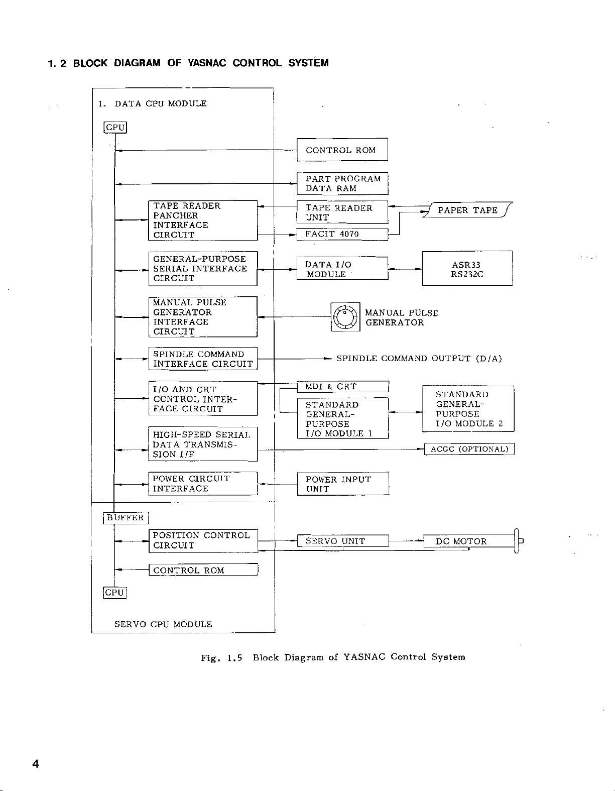
BLOCK
DIAGRAM
1.
DATA
CPU
CPU
YASNAC
OF
MODULE
CONTROL
SYSTEM
CONTROL
PART
DATA
TAPE
READER
PANCHER
INTERFACE
CIRCUIT
GENERAL-PURPOSE
SERIAL
CIRCUIT
MANUAL
GENERATOR
INTERFACE
CIRCUIT
I
SPINDLE
INTERFACE
I/O
CONTROL
FACE
HIGH-SPEED
DATA
SION
INTERFACE
PULSE
COMMAND
AND
CRT
INTER¬
CIRCUIT
TRANSMIS¬
I/F
CIRCUIT
i
SERIAL
TAPE
UNIT
FACIT
DATA
MODULE
MDI
STANDARD
GENERAL-
PURPOSE
MODULE
I/O
ROM
PROGRAM
RAM
READER
4070
I/O
'
o
SPINDLE
CRT
&
MANUAL
GENERATOR
1
PULSE
COMMAND
PAPER
ASR33
RS232C
OUTPUT
STANDARD
GENERAL-
PURPOSE
MODULE
I/O
(OPTIONAL)
ACGC
TAPE
(D/A)
7
2
POWER
BUFFER
I
'
INTERFACE
POSITION
CIRCUIT
CONTROL
CIRCUIT
CONTROL
ROM
POWER
UNIT
SERVO
INPUT
UNIT
DC
MOTOR
CPU
SERVO
CPU
MODULE
Fig.
1.5
Block
Diagram
YASNAC
of
Control
System
4

MAINTENANCE
1.
3
(1)
Measuring
INSTRUMENTS
instruments
(2)
•
Phillips
•
Standard
1.
4
The
Tools
screwdriver:
ROUTINE
following
Name
AC
voltmeter
DC
voltmeter
Oscilloscope
DC
ammeter
screwdrivers:
INSPECTION
table
shows
Items
Capable
Tolerance:
Maximum
Tolerance:
(A
2-channe]
range
Maximum
Tolerance:
large,
medium
SCHEDULE
the
of
digital
of
medium
and
minimum
Specifications
measuring
-2%
range:
-2%
voltmeter
type,
5
MHz
range:
i2%
and
small
Table
or
less
10
V,
or
less
may
with
or
higher
A,
10
or
less
small
require-
1.3
AC
power
30
V
be
a
frequency
A,
30
Inspection
Frequency
voltage
required.)
50
A
(3)
•
Cleaning
alcohol)
ments
order
for
To
To
To
waveforms,
To
through
Chemicals
to
to
keep
an
extended
Schedule
*4-*
5
E
5
O
as
as
%
s
sr
measure
measure
measure
measure
agent
be
C
E
<o
r
Purpose
AC
DC
tape
etc.
currents
DC
motors
observed
the
equipment
period.
power
power
for
reader
for
voltages
voltages
output
flowing
tape
Remarks
reader
maintenance
in
optimum
(absolute
time
condition
'
in
Tape
Reader
Control
Panel
Servomotor
Cleaning
head
Cleaning
tumble
Lubrication
arm
shaft
Tight
closing
doors
Checking
and
gaps
and
worn
Vibration
Motor
contamination
and
breakage
Burned
wear,
of
brushes
Roughened
surface
Dirt
in
motor
Battery
box
spots,
and
interior
of
reading
of
tape
of
end
of
for
loose
of
side
door
and
pressure
commutator
tension
gaskets
noise
cracks,
of
fit
plates
Daily
Weekly
As
Daily
Monthly
Daily
Daily
required
Every
three
Daily
required
or
months
O
Including
light
source
part.
O
O
O
O
by
hand,
and
do
Feel
O
audible
as
o
O
O
O
O
O
O
Inspect
Check
brushes.
Check
and
Clean
See
displayed
inspection.
visually.
the
dark
grooving
with
if
alarm
length
bar,
of
compressed
for
on
CRT
the
_
of
threading
commutator.
air.
BATTERY
screen.
is
5

4.
1.
(1)
(a)
glass,
stained
gauze
clean
1
TAPE
Cleaning
Remove
with
with
or
the
a
soft
tape
READER
the
tape
tape
rubbish
blower
or
oil
cloth
guide
reader
oily
with
and
brush.
dust,
absolute
the
head
and
tape
(Daily)
dust
If
wipe
alcohol.
retainer.
the
it
from
glass
using
the
Also
(b)
After
inspecting
close
door)
YE001).
is
key
a
it
key
position
all
clicks
can
the
securely
when
the
(approximately
be
.
door
way
and
using
opening
into
removed
the
fasten
the
control
the
or
keyhole
a
from
door
key
closing,
quarter-turn).
an
with
locks
provided
and
open
door
insert
turn
or
open,
(2
closed
per
(No.
the
until
The
(b)
source)
(2)
(a)
clean,
(b)
1.2)
the
brush.
(3)
For
reels,
when
1.
4.
(1)
(a)
proof,
so
door
Remove
Cleaning
Clean
soft
Remove
by
bottom
Lubricating
the
lubricate
the
(In
When
winding
open
dust
blower
a
2
CONTROL
Checks
The
sheet-steel
as
to
tightly
on
top
of
the
cloth.
loosening
of
control
tension
V
\
the
trouble
tape
the
around
brush.
on
control
keep
closed
the
with
tape
braided
the
the
of
Q
case
front
the
doors
off
dust,
a
tumble
tape
two
tape
tension
with
shaft
the
arm
TENSION
of
NOTE
occurs
8
with
door
photo-coupler
PANEL
for
panel
enclosure
dust
at
if
blower
nylon
outlet
mounting
tumble
inch
6
does
8-inch
inch
tight
is
constructed
and
times.
all
any,
box
on
brush.
(Weekly)
leading
cover
screws
box
shaftt
arm
or
8
of
end
move
not
LUBRICATING
ARM
diameter
feeding
in
diameter
and
brush
by
closing
with
gasketed
oil
mists.
LED
tape
(See
and
with
inch
tension
smoothly.
reel)
reels,
away
using
(Daily)
as
Keep
(light
with
Fig.
clean
cloth
diameter
arm,
or
.
dust-
a
doors
each
a
or
CLOSED
POSITION
If
is
the
operations.
(c)
Check
doors.
(d)
See
Clean
(e)
the
it,
Check
doors
1.4.3
SPINDLE
(1)
Vibration
Vibration
motors,
the
stick
found,
ately
(2)
Check
damage
by
machine
is
.
Motor
removing
0
CLOSED
With
lock
side
door
Hinged
the
provided,
main
if
if
shut
SERVOMOTOR
can
recommended.
contact
the
should
tool
T
OPEN
the
door
on
right
of
the
(Left-hand
Door)
optional
opening
power
gaskets
the
inside
necessary.
for
any
tightly.
and
noise
checked
be
and
maintenance
contamination
motor
be
the
machine
builder's
exterior
POSITION
NOTE
door
supply
on
the
opening
AND
(Daily)
noise,
for
and
observed,
manual.
OPEN
With
lock
side
door
Hinged
interlocking
the
door
and
rims
of
enclosure
the
in
DC
by
resting
using
any
If
personnel
impairment
visually.
inspect
cover.
POSITION
©
the
on
of
(Right-hand
shuts
stops
of
front
door
MOTOR
abnormality
Refer
CLOSED
_
_
door
left
the
Door)
switch
and
is
base
the
listening
a
(Daily)
If
the
CLOSED
POSITION
off
all
rear
dusty.
with
FOR
on
hand
immedi¬
dirt
or
motor
to
the
is
tTension
6
arm
shaft
available
as
an
option.

(3)
Carbon
(a)
around
cause
The
carbon
the
motor
armature
worst
the
avoid
this,
commutators
months.
power
Under
wear
check
off
inspecting
unit
fatal
by
is
Double
turning
before
(Disconnecting
supply
off
cause
(b)
wears
If
contaminated
overcurrent
(c)
When
those
shown
one.
If
brush
.
When
consult
motor
either
Minertia
(d)
the
unit
brushes
commutator,
troubles
the
and
case,
sure
be
and
to
both
the
for
completely).
or
serious
normal
2
to
excessive,
armature
flows
brush
below,
junior
the
assembly
PIGTAIL
replacing
YASNAC
dust
it
control
brushes
servo
4
may
brushes
mm
through
length
(Quareerly)
from
such
flashover
lead
to
have
be
sure
power
circuit
control
injury.
operating
per
check
surface,
replace
series:
brush,
must
c
NOTE
the
service
brushes,
inside
as
the
of
to
fatal
an
least
at
power
and
servomotor
breaker
Failure
conditions,
1000
to
motor
becomes
the
6
or
pigtail
be
replaced
'
---
BRUSH
LENGTH
brush
personnel.
accumulated
the
motor,
layer
commutator.
damage.
inspection
every
is
and
servo
of
cannot
unit
to
do
operating
see
or
if
circuit.
shorter
brush
mm
with
or
is
1
assembly,
short
OFF
the
if
abnormal
below
broken,
as
a
on
three
power
inside.
power
shut
so
brush
hours.
oil
than
a
whole
may-
may
new
To
the
by
has
of
In
(4)
Commutator
(a)
Visually
commutator
After
100
should
chocolate
ideal
other
(b)
ing)
is
Threading
may
blackened
commutator
than
See
is
observed,
be
commutator
sparkings.
blackened
cloth
dry
occurs,
(5)
Motor
(a)
Visually
inspection
dried
The
running,
parts
brushes
(air
pressure:
(b)
If
due
to
contact
(6)
Servomotor
As
the
is
5000
company
the
If
possible,
hours
1.44
Make
position
is
sure
blinking,
battery
month.
a
through
to
200
take
color.
to
a
if
blackened
the
on
investigate
or
due
bar
slots,
If
bar,
to
contact
inside
window.
carbon
but
such
oily
be
as
cleaned
carbon
poor
YASNAC
life
expectancy
hours,
should
yearly
recommended.
BATTERY
that
CRT
of
contact
must
surface
check
inspection
operating
a
on
The
film
be
kept
commutator.
grooving
to
too
is
the
the
wipe
smooth
the
maintenance
(dirty)
check
is
it
commutator,
kg/cm2,
2-4
dust
oil
seal
service
with
the
inspection
inspection
"BAT”
screen
maintenance
be
replaced
(Quarterly)
surface
hours,
polished
motor
and
clean.
bar,
threading
cause
the
on
the
result
accidentally
commutator
the
motor
exists
or
of
dust
surface.
will
a
defective
small
or
carbon
the
the
dust
recommended
with
personnel.
oil
seal
of
oil
done
be
or
"A/B"
does
with
roughness
window.
the
light
has
needs
If
developed
any
of
commutator
motor
a
of
carbon
is
representative.
interior
not
that
brush-holders
dry
compressed
28.5-56.5
inside
seals
and
maintenance
every
taking
on
not
blink.
personnel.
new
a
commutator
brown
no
attention
(or
of
the
trouble.
load.
dust
produced
cause
a
with
If
sparking
through
affect
the
ps)
the
enclosure,
and
brushes
5000
less
the
right-low
one
of
the
groov¬
above
surface
clean
a
motor
inner
and
motor
hours.
than
If
it
The
within
or
an
A
in
of
air
by
8
is
7
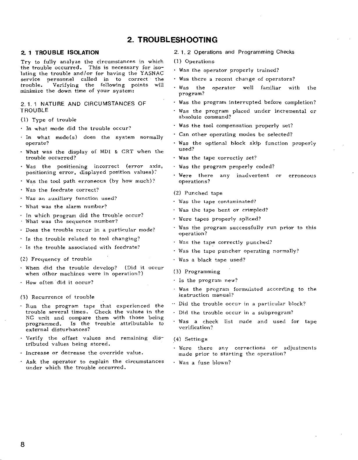
2.
TROUBLESHOOTING
1
TROUBLE
2.
fully
to
Try
trouble
the
lating
the
service
trouble.
minimize
2.1.1
NATURE
TROUBLE
(1)
Type
•
In
what
In
what
operate?
•
•
-
•
•
•
•
•
•
•
(2)
•
•
(3)
•
•
•
•
was
What
trouble
Was
the
positioning
the
Was
the
Was
Was
an
What
was
In
which
What
was
Does
the
the
Is
the
Is
Frequency
When
when
How
Run
did
other
often
Recurrence
the
trouble
NC
unit
programmed.
external
Verify
tributed
Increase
the
Ask
under
analyze
occurred.
trouble
personnel
Verifying
down
the
trouble
of
mode
mode(s)
the
occurred?
positioning
error,
tool
path
feedrate
auxiliary
the
program
the
trouble
trouble
trouble
of
the
machines
did
program
several
and
disturbances?
the
offset
values
or
decrease
operator
which
the
ISOLATION
the
This
and/or
called
the
of
time
CIRCUMSTANCES
AND
trouble
the
did
does
displayed
erroneous
correct?
function
number?
did
recur
were
occur?
trouble
tape
the
values
to
trouble
of
the
to
develop?
stored.
the
explain
display
alarm
sequence
related
associated
trouble
trouble
it
of
times.
compare
Is
being
circumstances
necessary
is
for
having
in
to
following
your
system:
occur?
the
system
&
MDI
incorrect
position
(by
used?
trouble
number?
a
particular
in
changing?
tool
feedrate?
with
in
operation?)
experienced
that
Check
them
the
with
trouble
and
override
the
occurred.
in
YASNAC
the
correct
points
OF
normally
CRT
when
(error
values)?
much)?
how
occur?
mode?
(Did
it
values
those
attributable
remaining
value.
circumstances
for
which
iso¬
axis,
occur
in
being
dis¬
the
will
the
the
the
operators?
familiar
Checks
with
the
(1)
•
•
2.
1.
Was
Was
V/
Operations
2
Operations
the
there
the
as
operator
recent
a
operator
Programming
and
properly
change
trained?
of
well
program?
•
Was
•
Was
absolute
Was
Can
•
Was
the
the
the
other
the
program
program
command?
tool
operating
optional
interrupted
placed
compensation
modes
block
under
properly
skip
before
be
function
incremental
set?
selected?
completion?
or
properly
used?
•
•
*
Was
Was
Were
the
the
tape
program
there
correctly
properly
any
set?
coded?
inadvertent
or
erroneous
operations?
(2)
•
•
•
Punched
Was
Was
Were
Was
the
the
the
tapes
tape
tape
tape
properly
program
contaminated?
or
bent
spliced?
successfully
crimpled?
run
prior
to
this
operation?
•
Was
the
tape
correctly
•
Was
the
tape
puncher
•
(3)
•
••
•
•
to
(4)
•
•
a
Was
black
Programming
the
program
the
Is
Was
instruction
Did
the
Did
the
Was
a
verification?
Settings
Were
made
Was
a
there
prior
fuse
program
manual?
trouble
trouble
check
to
blown?
tape
new?
occur
occur
list
any
starting
operating
used?
formulated
in
in
made
corrections
punched?
a
particular
a
subprogram?
and
the
operation?
normally?
according
used
or
to
block?
for
tape
adjustments
the
8

•
Was
•
Was
•
Was
What
•
Was
board)
•
Was
Was
•
Was
Was
(5)
External
•
Was
justed?
Was
adjusted?
•
Was
•
Is
frequency
machine,
range?
•
Was
nearby?
•
Is
similar
Has
inside
•
Has
this
(6)
•
What
•
Was
•
Was
•
Was
the
•
Were
•
Was
2.
.
1
(1)
Control
•
Was
Was
•
Was
•
Was
Did
interior?
an
the
an
was
the
?
the
the
the
the
the
the
the
there
there
there
the
the
the
unit?
Ambient
was
there
the
there
immediate
there
the
3
NC
the
the
the
the
any
emergency
machine
the
state
alarm
alarm
alarm
MODE
override
machine
hold
feed
factors
machine
control
NC
unit
any
sewing
welding
any
other
any
failures
user
NC
same
conditions
the
temperature?
any
reader
tape
any
any
system
UNIT
unit
ft
MDI
tape
reader
tape
reader
unit
operated
machining
tool
lamp
switch
set
lock
set?
tool
cabinet
recently
noise
new
in
your
made
unit?
trouble
abrupt
oil
area?
vibrations?
exposed
CHECK
exterior
CRT
stop
maintained?
ready
in
effect?
number?
on
lit
in
normal
to
"0"?
set?
recently
source
machine,
machine)
machine
NC
unit
factory?
attempt
an
occured
change
contaminated?
or
cutting
to
unit
normal?
clean?
kept
door
closed?
with
chips
operate?
to
a
module
recently
repaired
(e,g.,
electrical
within
recently
that
in
fluid
the
its
enter
(on
position?
repaired
repaired
or
crane,
interference
has
at
adjustments
previously
temperature?
splashed,
direct
door
open?
the
printed
ad¬
or
adjusted?
high
discharge
installed
developed
with
sunlight?
cabinet
(2)
•
V/
as
What
from
(3)
•
Was
•
Was
the
normal?
•
Was
(4)
Was
’
•
Were
or
+24
Was
•
Was
•
Was
•
Was
•
Was
reader
Tape
the
were
the
Control
the
the
flow
air
)
the
Composite
the
the
V,
±15
each
fuse
a
the
the
the
tape
the
tape
unit
control
fan
interior
input
output
V)?
voltage
blown?
circuit
shield
wiring
reader
characteristics
reader?
interior
unit
motor
from
the
damaged
power
supply
voltage
voltages
within
breaker
properly
properly
contaminated?
of
interior
contaminated?
operating
cooling
by
corrosive
unit
normal?
normal
tolerance?
tripped?
grounded?
inside
the
normally?
air
exhaust
(+5
the
waveforms
(Was
port
gas?
V,
+12
control
V,
cabinet?
•
How
much
did
the
input
•
Was
there
any
voltage
significant
fluctuate?
drop
in
input
voltage?
•
Was
interlock
•
there
Is
amount
ing
(5)
Grounding
•
Was
•
Was
(6)
in
Cables
Were
•
Was
•
Was
•
Was
front
the
in
of
machine,
grounding
shield
the
cable
internal
any
external
any
cable
any
effect)?
any
current
electrical
connectors
broken
or
rear
machine
in
properly
grounding
cable
cable
that
the
discharge
connected?
securely
damaged?
damaged?
or
open
door
consumes
factory
proper?
contaminated?
(with
(e.g.,
machine)?
inserted?
a
door
large
weld¬
9

1.
2.
3
(7)
Modules
•
Were
•
Were
•
What
•
Were
modules
(8)
MDI
•
Can
normally?
(9)-
Parameters
Did
the
parameter
(10)
Interface
•
Were
installed?
•
Was
Were
equipped
•
Were
DGN
(11)
ACGC
Can
the
normally?
rear
panel
NC
UNIT
(on
modules
all
connectors
plug
the
was
connections
correct?
&
CRT
the
power
actual
table
power
the
cable
the
the
relay,
with
I/O
the
(diagnostic)
(option)
power
Is
in
printed
revision
unit
parameters
attached
positively
a
signals
the
tact?
CHECK
securely
supply
cable
solenoid,
noise
function?
supply
5A
(Cont’d)
circuit
installed?
properly
letter?
(on
flat
be
turned
match
to
the
NC
and
shielded?
suppressor?
normally
be
turned
glass-encased
board)
secured?
cable)
NC
cable
motor,
generated
those
unit?
on
fuse
between
on
and
separately
etc.
and
in
by
on
the
each
the
off
the
off
1.
ALARM
338:
310:
201:
013:
l
Depress
This
and
importance,
top.
an
In
appears
display.
.PAGE.
the
(
(ALM)
the
cause
will
alarm
messages
with
alarm
taking
state,
priority
There
key.
>
i
EMERGENCY
(X)
ERROR
Alarm
OFF
Codes
SERVO
0T
PROG
up
the
NOTE
is
STOP
key
to
no
(NO
4
to
most
the
and
of
pairs
appear
serious
alarm
over
any
need
to
00010
ADDRESS)
BUF
Messages
alarm
in
order
one
screen
other
operate
ALM
codes
the
at
N0017
of
2.2
TROUBLESHOOTING
If
an
"A/B"
line
of
function
the
alarm
following
alarm
(for
CRT
the
In
.
condition
operations:
condition
battery
this
000
100
200
300
400
500
600
700to799
800
900to999
screen
Alarm
to
to
to
to
to
to
to
to
occurs,
alarm)
case,
No.
099
199
299
399
499
599
699
899
BY
regardless
detailed
will
ALARM
a
blinks
be
displayed
Spindle
Stop
Stop
Decelerated
Decelerated
Decelerated
Immediate
NG
system
display
on
of
information
Operation
block
at
at
block
stop
CODE
"ALM"
the
the
end
end
to
stop
to
stop
to
stop
stop
bottom
mode
by
or
or
of
the
Table
Tape
Macro,
sequence
Overtravel,
machine
Servo,
Sequence
Sequence
Sequencer
CPU
Contact
Off-line
2.
2.1
format
operation,
ready
emergency
error,
YASNAC
error
Eliminate
the
the
the
and
selected
The
error
error
reference
error
error
message
RAM
(RESET)
alarm
alarm
"840"
function
alarm
Type
alarm
external
(1)
stop,
(2)
(3)
error,
service
the
display
codes
are
codes
of
point
overload
ROM
personnel.
cause
key,
"800,"
displayed
key.
are
Alarm
input/output
return,
error
the
of
and
be
will
categorized
positioning,
FG,
the
"810,
error.
RPG
alarm
alarm
reset.
"
regardless
and
Notice
"820,
as
depress
state
"830"
"
of
follows:
and
that
the
10

:
2.
Code
2.
000
001
002
003
004
LIST
1
POWER
SETTING
REQUIRING
ZR
REFERENCE
COMPLETED
ZR
REFERENCE
COMPLETED
ZR
REFERENCE
COMPLETED
ZR
REFERENCE
COMPLETED
ALARM
OF
OFF
THE
UNREADY
UNREADY
UNREADY
UNREADY
CODES
Causes
PARAMETER
TURNING
(X)
POINT
X.
(Y)
POINT
Y.
(Z)
POINT
Z.
(4)
POINT
4.
OFF
RETURN
RETURN
RETURN
RETURN
Table
POWER.
NOT
NOT
NOT
NOT
2.2
List
of
Code
Alarm
014
015
016
017
020
Codes
PROG
SIGN
PROG
ERROR
ERROR
UNUSABLE
"0"
CHARACTER
INSIGNIFICANT
PROG
INPUT
AS
PROG
INPUT
CHARACTERS)
PROG
INCLUDED
ERROR
OF
ADDITIONAL
ERROR
DATA
ERROR
UNUSABLE
A,
G
IN
Causes
"0")
CORRECTLY
NOT
(UNUSABLE
DATA
(UNUSABLE
V,
C,
U,
B,
OR
AXIS
DIGITS)
(8
OVERFLOW
.
(G)
CODE
ORGCODE
OPTIONS
USED.
CH)
PROGRAMMED
AREA.
AXIS)
DEFINED
NOT
W
FUNCTION.
B-
(MORE
THAN
NOT
PROGRAMMED.
IN
8
005
010
011
012
013
NOTES:
No
1.
at
MOO
2.
3.
Rise
UNREADY
ZR
REFERENCE
COMPLETED
ERROR
TH
TAPE
TV
TAPE
HORIZONTAL
ERROR
VERTICAL
OVERFLOW
BUFFER
BLOCK
PROG
XD
ADDRESS
PLUS
move
G41
commanded
at
CAPACITY
(128
ERROR
DRESS'
DATA.
command
(G42)
circular
(5)
POINT
RETURN
5.
PARITY
PARITY
CH)
(128
(NO
OVERFLOW
ADDRESS)
15
ATA"
CHARACTERS).
PLUS'NS
COMMANDED.
three
in
command,
rise.
when
interpolation
NOT
ERROR.
ERROR.
IN
ATJD~NEXT'
NO
block.
ADDRESS
in
OR
blocks
A
series
021
022
023
024
025
IN
(G)
4,
1,
PROG
CODE
G
ERROR
SIMULTANEOUSLY
PROG
G43,
ERROR
G44
(G02/03,
COMMANDED
INTERPOLATION
CODE
G
CYCLE.
CODE
(G)
(G.
PROG
UNUSABLE
CANNED
PROG
ERROR
ERROR
UNUSABLE
COMPENSATION
PROG
G70
TO
CANNED
ERROR
G72
(G70/71/72)
COMMANDED
CYCLES.
GROUP
*
IN
MODE
COMMANDED
G41/42)
PROGRAMMED
BLOCK.
A
G43/44)
CIRCULAR
IN
(G02,
COMMANDED
MODE.
EXCEPT
.
G03)
IN
DURING
IN
.
11

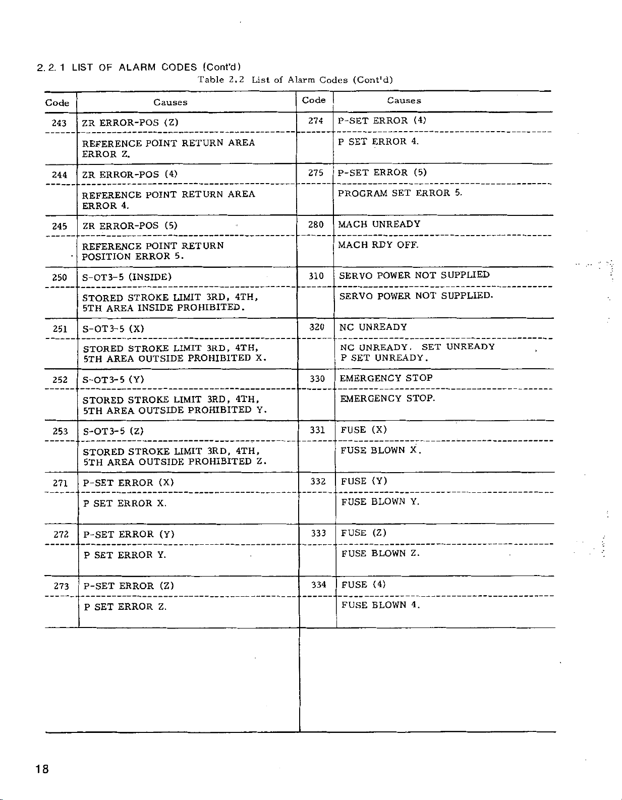
2.2.1
LIST
OF
ALARM
CODES
(Cont’d)
Table
2.2
List
of
Alarm
Codes
(Cont'd)
Code
026
027
030
031
032
033
034
PROG
RISE
WHICH
RECTLY
PROG
ERROR
IN
PROG
NO
PROG
CIRCLE
IN
PROG
COMMANDS
ARC
PROG
ERROR
"ERROR”
CANNOT
IN
ERROR
AT
CIRCULAR
ERROR
F-COMMAND
ERROR
WITH
CIRCULAR
ERROR
COMMAND
ERROR
ajMMffiffiS
CULAR
ARC
SELECTED
PROG
ERROR
Causes
(G41/42)
a5ÿENSA7fiON
AT
ACCOMODATED
BE
COMPENSATION
(G41/42)
COMPENSATION
INTERPOLATION
(F)
IN
FEED
0)
(R
=
RADIUS
ARC
(G02/03)
THREE
ON
0
COMMAND
AXES
WITHOUT
(G02/03)
T
MORE"
ON
PLANE
FROM
(G02/03)
WHOSE
THE
HAN
COMMAND
"(COMMAND
~C
COR¬
MODE)
C
C
SEE
(ERROR
MODE)
COMMAND
COMMANDED
CIRCULAR
IN
HELICAL
“TO
UR
AXES
CANNOT
ARC
NOTES
OPTION
OR'-
"IN"
BE
Code
038
;
040
041
042
044
045
NOT
P
P
DIFFERENT
G25
CIRCLE
US
R
ERROR
LARGE
IS
ERROR
PROGRAMMED
AND
M98/M99
ERROR
"NO"."
WHEN
G65,
M99,
ERROR
NESTED.
ERROR
SMALLER
IS
ERROR
PROG
TOOL
SYSTEM
PROG
•
•
•
PROG
PROGRAM
FOUND
M98,
PROG
SUBPROGRAM
FIVE-
PROG
IN
CAL
Causes
G10)
(P,
P
WHEN
WORK
PROGRAM-INPUT
G65/66)
(M98,
G65,
M98,
IN
Q
FROM
(M08/09,
NO.
IN
PROGRAMMED
G65/66)
IN
SIMULTANEOUSLY.
"(SEQUENCE
PROGRAM
G66,
(M98,
(G25)
(G12)13)
CUTTING,
(G41/42)
IS
G,
G25,
NEST)
OR
MACRO
PROGRAMMED
THAN
COMPENSATION
COORDINATE
G66,
G25.
G25MODE.
"NO".")"
CALLED
M,
NOT
BY
T
CALL
""
RADI¬
D.
035
036
037
CIRCULAR
PROG
TO
TOOL
6“
LA
ERROR
RADIUS
LENGTH
PROG
TOO"!
TION)
ERROR
ARGE
WHEN
-INPUT
PROG
TOOL
ERROR
LARGE
SYSTEM
ARC
"N
GE
R
DESIGNATION
R
H)
(D,
"
d~.
0"F
COMPENSATION
COMPENSATION
G10)
(P,
"("NUMBER"
"P
OFFSET
(P
GI0)
,
WHEN
R
IS
PROGRAM-INPUT
"6
"H
IS
WORK
R"
ODE
C
D'
AND
DESIGN
A-
PROGRAM
COORDINATE
ERROR
-FOR
TOOL
"“"
046
047
048
PROG
I
ARC
N“
CO
ERROR
N
SAT
MPE
OUTSIDE
PROGRAMMED.
PROG
ERROR
COMPENSATION
COMPENSATION
PROG
ERROR
INTERSECTION
INTERSECTION
(G41/42)
~C
O
I
OF
(G41/42)
(G41/42)
MOD
N
COMPENSATION
PLANE
C
POINT
CHANGED
MODE
NOT
COMPUTATION
”
E",
CIRC
OBTAINED
ULA
R"
PLANE
DURING
BY
"
12

Table
2.2
List
of
Alarm
Codes
(Cont'd)
Code
049
050
051
055
056
058
PROG
ERROR
REVERSE
MANDED
SCALING
BLE
USA
UN
TO
G36
MODE.
SCALING
ERROR
FORMAT.
PROG
M,”
IN
BE
PROG
AXIS
G21
ERROR
”f
S7
WHICH
COMMANDED
ERROR
COMMAND
BLOCKS.
MIRROR
Causes
(G41/42)
ALMOST
OR
IN
ERROR
G38,
ERROR
IN
“B
7
IMAGE
MODE.
M97
OD
“G
”C
E~
G70
TO
AND
G51
AUNG
SC
(M.
S,
"COMMANDS
M,
T.
S.
(AXIS)
IN
(G28)
REVERSE
(
G
9
27
G72)
BLOCK
G50
FACTOR
B)
T,
"FN
CODE
B
G04,
~G
IN
_T
G20,
28~
COM¬
TO
“G
SCALING
ZERO.
LOCK
HE
B
CANNOT
AND
Code
070
6
3
7
075
076
077
PROG
MEMORY
NOT
RS232C
RS232C
NO.
RS232C
DATA
THROUGH
RS232C
“MORE
MITTED
080
084
ERROR
GIVEN.
OF
TRANSMISSION
THAN
IN
READ
PROG
G10,
AXIS
MIRROR
ERROR
G22,
DATA.
OPERATION
INTERFACE
BITS
AFTER
THROUGH
IMAGE
Causes
(M02/30/99)
NO.
AND
RS232C
TO
AND
INTERFACE.
CHÿCTÿS'HAW
STOP
RS232C
(G10,
G23
(G36/37/38)
FINISH
DISAGREEMENT
FAILURE
CODE
G22/23)
COMMANDED
COMMAND
BAUD
OF
HAS
INTERFACE.
BEEN
OF
RATES.
BEEN
TRANS¬
WITH
059
066
068
COMMANDED
G28
IMAGE.
UNREADY
ZR
G28
NOT
COMMAND
G29
RETURN
RESET
EDITING
EDIT
INHIBIT
COMPLETED
UNREADY
NOT
COMPLETED
BEING
OR
EXECUTED
AREA.
DURING
ON
THE
REFERENCE
(AFTER
MIRROR
AXIS
WHICH
POINT
ON
THE
EDITING)
IN
THE
AXIS.
HAS
085
086
087
088
MIRROR
IMAGE
G38.
PROG
ERROR
COMMAND
AT
AXIS
PROG
COMMAND
PROG
TOUCH”
REACHES
TO
PROG
TOUCH
AT
ERROR
ERROR
S
COMMANDS.
G38
ERROR
SWITCH
G36
TO
(G36/37)
I
OF
(G37).
G36
(G38)
OTHER
(G31/36/37/38)
WIT
CH
END
AT
(G36/37/38)
G38
IS
(J)
“NOT
WITH
ON
ON
THAN
“ON“
POINT
MORE
K
WHEN
BY
CALCULATION
COMMANDS.
G36
AT
TO
THAN
G38.
MOTfO
G31,
ERROR
ONE
N
G36
13

2.2.1
LIST
OF
ALARM
CODES
(Cont’d)
Table
2.2
List
of
Alarm
Codes
(Cont'd)
Code
100
101
102
103
104
105
106
MACRO
CONSTANTS
EXCEEDING
MACRO
CAL
ERROR
MAGNITUDE
EXCEEDING
CAL
ERROR
EXPONENT
OF
EXCEEDING
ERROR
CAL
CALCULATION
OVERFLOW
CAL
ROOT
PROG
SAME
BLOCK.
ERROR.
ERROR
VALUE
(-)
ERROR
ADDRESS
ERROR
ERROR
Causes
(FIXED
OF
UPPER
(FLOATING)
POINT)
FIXED
LIMIT
FLOATING
ALLOWABLE
(DIVISION)
DIVISOR
(SQUARE
IS
A
NEGATIVE
(DOUBLE
REPEATED
(CONSTANT)
USABLE
THE
IN
LIMIT.
POINT
POINT
RANGE
ZERO
ROOT)
ADD)
USER
IN
DATA
DATA
OR
A
MACRO
Code
114
115
116
117
118
120
121
MACRO
NO.
MACRO
NO.
OF
OF
ERROR
DOs
ERROR
LEFT
BRACKETS
MACRO
ERROR
CONDITION
NOT
ESTABLISHED
MACRO
CONDITION
OR
PRTN
SEQUENCE
NO
ERROR
ERROR
SEQUENCE
PROGRAM.
ERROR
PRTN
(DO-FORMAT)
AND
((
BRACKETS
NOT
THE
(DO-END
l<n<3
(GOTO
0<nS9999
(NOT
NOT
NO.
(G92)
Causes
ENDs
•]
IN
NO.
FOUND)
NOT
UNMACH)
AND
SAME.
NO.)
DOn.
N)
NOT
ESTABLISHED
GO
IN
FOUND
THE
TO
IN
SAME.
RIGHT
n.
PART
TOO
FOR
107
MACRO
ERROR
EQUATION.
MACRO
108
UNDEFINED
DESIGNATED.
MACRO
109
COMMANDED
AS
SIDE
110
MACRO
MULTIPLE
EXCEEDING
111
MACRO
MOVE
MAND
112
MACRO
MANY
G
CODES
CANCELLING
ERROR
IN
THE
ERROR
VARIABLE
ERROR
PROHIBITED
SUBSTITUTION
OF
THE
EQUATION.
ERROR
LAYERS
THE
ERROR
COMMAND
MACRO
OF
ERROR
COMMANDED
G67.
(FORMAT)
FORMAT
(UNDEFIN#NO)
(
#NO
([
UPPER
(MOVE
IN
CALLED
(5)
AND
NO.
LEFT)
NOT
IN
]5
OF
VARIABLE
LEFT-HAND
LIMIT)
PARENTHESIS
LIMIT
G66-M99)
FINISHING
M99
BY
(5).
G66.
COM¬
G92
ATION
PRTN
122
G54
OPERATION
123
PRTN
COORDINATE
DEPRESSING
PROGRAM
124
PRTN
AXIS
PROGRAM
PROG
125
ERROR
T,
PROG
126
TOOL
COMMANDS
127
LIFE
COMMANDED
DURING
ERROR
TO
COMMANDED
G59
DURING
ERROR
RESTART.
ERROR
OPERATED
RESTART.
ERROR
EXISTS
L,
H,
AND
ERROR
LIFE
CONTROL
EXCEEDED
ERROR
CTRL
THROUGH
PROGRAM
(G54-G59)
PROGRAM
(ORG)
SYSTEM
ORG
THE
(MDI
MOVE)
BY
MDI
(G122/123/124)
IN
SPECIFICATION
D
WITH
(G122
DATA
DATA
(T5
MDI
RESTART.
THROUGH
RESTART.
CHANGED
BUTTON
AFTER
COMMANDS
OVR)
CAPACITY
T9999)
&
OPER¬
MDI
BY
DURING
OF
G122/123.
P,
I,
14
LEVEL
FOR
EXCEEDING
CALLING
FOUR
MACRO
LEVELS.
ENTERED
COMMAND
REGISTERING
ERROR
IN
THE
THE
T9999L
FOR
GROUP
AAA
T5
DIGITS
OR
THERE
COMMAND.
WITHOUT
IS
AN

Table
2.2
List
of
Alarm
Codes
(Cont’d)
Code
128
129
CTRL
LIFE
ENTERED
ALTHOUGH
OF
THE
GROUP
ENTERED
OR
OUT
REGISTERING
AND
H-NO
PROG
ERROR
SPECIFIED
WORK
THE
MODE
WAS
Causes
ERROR
(T5&H9999)
COMMAND
OF
ALL
WERE
H(D)999
D-NO.
AN
TOOL
(G54
TO
EXCESSIVELY
COORDINATE
OTHER
THAN
FOR
T5
CONTENTS
THE
SKP
IN
COMMAND
NUMBERS
G59
SYSTEM
GOO/GOl.
DIGITS
J)
STATUS,
WITH¬
LARGE
OR
J
THE
IN
Code
145
146
147
170
172
173
PROG
ERROR
HIGH-SPEED
G102
NOT
ERROR
OR
PROG
PARAMETER
HIGH-SPEED
MEM
ERROR
TOOL
OFFSET
ERROR
MEM
SETTING
MEM
AREA
ERROR
PARAMETER
Causes
(G100)
CUTTING
CANCELLED
(PARAMETER
(D7)
#6008
CUTTING
(OFS)
TOTAL
(SET)
TOTAL
(PRM)
TOTAL
AREA
COMMAND
BY
G100.
ON)
TO
SET
COMMAND.
CHECK
ERROR
CHECK
CHECK
G101
1
AT
ERROR
ERROR
!
!
;
140
141
142
G
G03
REGISTERED
CUTTING
143
144
PROG
ERROR
NO
AXIS
CUTTING
CUTTING
PROG
ERROR
NO.
OF
PROGRAM
VALUE
PROG
IN
ERROR
CODE
OR
PROG
ERROR
ADDRESS
G100,
G101
(P
COMMAND
PROGRAM
COMMAND.
(FILE
BLOCKS
EXCEEDING
HIGH-SPEED
(GOO/GOl
OTHER
S,
M,
T
PROGRAM
COMMAND.
(G101/G100)
OTHER
,
G
1
02
NG)
IN
AT
OVER)
IN
REGISTERED
THAN
CODE
THAN
BLOCK.
HIGH-SPEED
HIGH-SPEED
SPECIFIED
THE
CUTTING.
/G02)
GOO,
G01,
G02
COMMANDED
AT
HIGH-SPEED
COMMANDED
P
IN
AND
IN
174
175
179
180
MEM
ERROR
TOTAL
CHECK
VARIABLES.
MEM
ERROR
TOTAL
OVER
PANEL
HIGH
SEQ
SEQUENCE
CHECK
TEMP
INSIDE
ERROR
(KEEP)
ERROR
(MACR)
ERROR
TEMPERATURE
ERROR
(1)
OF
OF
MACRO
KEEP
TOO
MEMORY.
15

2.2.1
LIST
OF
ALARM
CODES
(Cont’d)
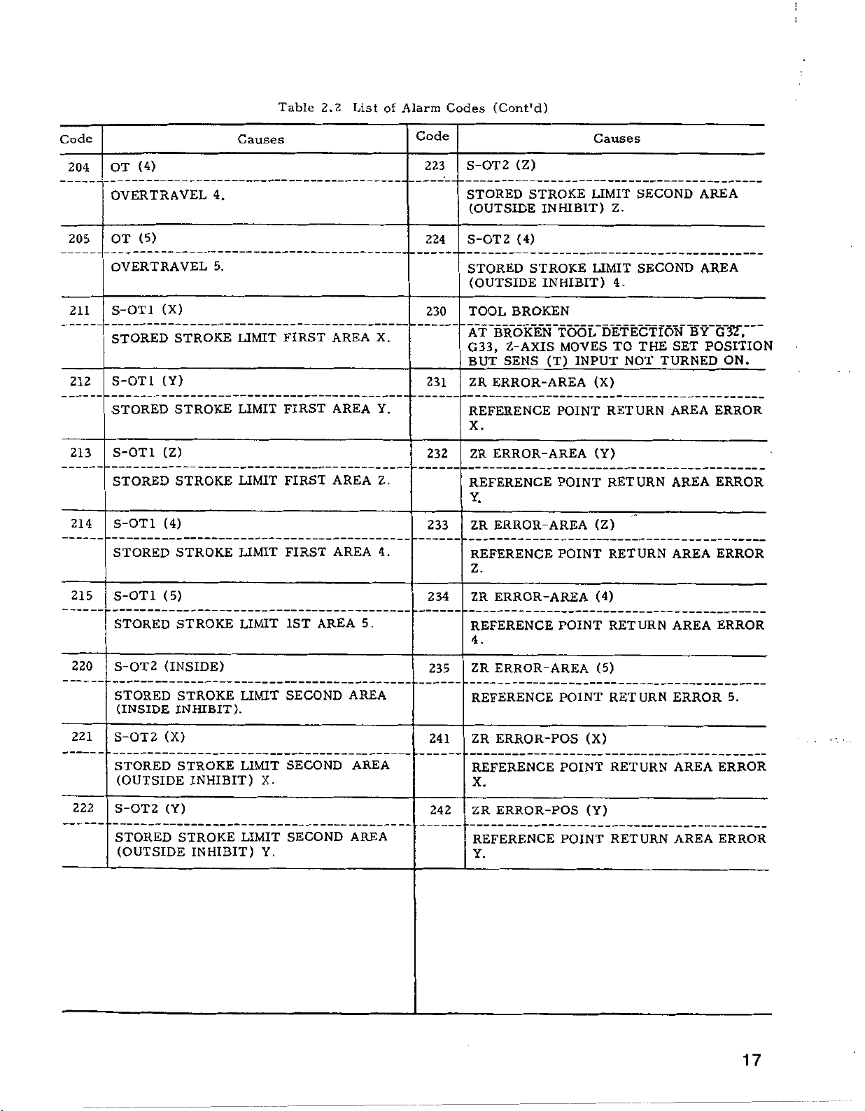
Table
2.2
List
of
Alarm
Codes
(Cont'd)
Code
Causes
Code
Causes
16
OT
201
OVERTRAVEL
OT
202
OVERTRAVEL
203
OT
OVERTRAVEL
(X)
X
<Y)
Y
(Z)
Z
!
Code
204
205
211
212
213
214
(4)
OT
OVERTRAVEL
(5)
OT
OVERTRAVEL
S-OT1
STORED
S-OT1
STORED
S-OT1
STORED
S-OT1
(X)
STROKE
(Y)
STROKE
(Z)
STROKE
(4)
4.
5.
Causes
LIMIT
LIMIT
LIMIT
Table
FIRST
FIRST
FIRST
2.2
AREA
AREA
AREA
List
X.
Y.
Z.
of
Alarm
Code
223
224
230
231
232
233
Codes
(Cont'd)
S-OT2
STORED
(OUTSIDE
S-OT2
STORED
(OUTSIDE
TOOL
'BROKEN
AT
G33,
BUT
ZR
ERROR-AREA
REFERENCE
X.
ZR
ERROR-AREA
REFERENCE
Y.
ERROR-
ZR
(Z)
STROKE
INHIBIT)
(4)
STROKE
INHIBIT)
BROKEN
Z-AXIS
SENS
"TOOL,'
MOVES
(T)
INPUT
POINT
POINT
AREA
Causes
LIMIT
LIMIT
SECOND
Z.
SECOND
4.
DETECTION'
TO
NOT
(X)
RETURN
(Y)
RETURN
(Z)
THE
TURNED
SET
AREA
AREA
AREA
AREA
G3T,
Y"
B
POSITION
ON.
ERROR
ERROR
215
220
221
222
STORED
S-OT1
STORED
S-OT2
STORED
(INSIDE
S-OT2
STORED
(OUTSIDE
S-OT2
STORED
(OUTSIDE
STROKE
(5)
STROKE
(INSIDE)
STROKE
INHIBIT).
(X)
STROKE
INHIBIT)
(Y)
STROKE
INHIBIT)
LIMIT
LIMIT
LIMIT
LIMIT
X.
LIMIT
Y.
FIRST
1ST
AREA
SECOND
SECOND
SECOND
AREA
AREA
AREA
AREA
.
4
234
5.
235
241
REFERENCE
Z.
ZR
ERROR-AREA
REFERENCE
4.
ZR
ERROR-AREA
REFERENCE
ZR
ERROR-POS
REFERENCE
POINT
POINT
POINT
POINT
(4)
(5)
(X)
RETURN
RETURN
RETURN
RETURN
AREA
AREA
ERROR
AREA
ERROR
ERROR
5.
ERROR
X.
242
ERROR-POS
ZR
REFERENCE
Y.
(Y)
POINT
RETURN
AREA
ERROR
17
2.2.1
LIST
OF
ALARM
CODES
(Cont’d)
Table
2.2
List
of
Alarm
Codes
(Cont'd)
Code
243
244
245
250
251
252
ERROR-POS
ZR
REFERENCE
ERROR
ZR
Z.
ERROR-POS
REFERENCE
ERROR
ZR
REFERENCE
4.
ERROR-POS
POSITION
S-OT3-5
STORED
5TH
S-OT3-5
STORED
5TH
S-OT3-5
(INSIDE)
STROKE
AREA
(X)
STROKE
AREA
(Y)
Causes
(Z)
POINT
(4)
POINT
(5)
POINT
ERROR
INSIDE
OUTSIDE
RETURN
RETURN
RETURN
5.
LIMIT
3RD,
PROHIBITED.
LIMIT
3RD,
PROHIBITED
AREA
AREA
4TH,
4TH,
X.
Code
274
275
280
310
320
330
Causes
P-SET
P
P-SET
PROGRAM
MACH
MACH
SERVO
SERVO
NC
NC
P
ERROR
ERROR
SET
ERROR
UNREADY
RDY
UNREADY
UNREADY.
SET
UNREADY.
POWER
POWER
EMERGENCY
SET
OFF.
(4)
4.
(5)
ERROR
NOT
NOT
STOP
SUPPLIED
SUPPLIED.
SET
5.
UNREADY
253
271
272
273
STORED
5TH
AREA
S-OT3-5
STORED
AREA
5TH
P-SET
P
SET
P-SET
SET
P
P-SET
SET
P
STROKE
OUTSIDE
(Z)
STROKE
OUTSIDE
ERROR
ERROR
ERROR
ERROR
ERROR
ERROR
(X)
X.
(Y)
Y.
(Z)
Z.
LIMIT
3RD,
PROHIBITED
LIMIT
3RD,
PROHIBITED
4TH,
4TH
,
Y.
Z.
331
332
333
334
EMERGENCY
(X)
FUSE
BLOWN
FUSE
FUSE
FUSE
FUSE
FUSE
FUSE
FUSE
(Y)
BLOWN
(Z)
BLOWN
(4)
BLOWN
STOP.
X.
Y.
Z.
4.
18

:
Code
335
341
342
343
344
FUSE
FUSE
SERVO
SERVO
SERVO
SERVO
SERVO
SERVO
SERVO
SERVO
{5)
BLOWN
ERROR
ERROR
ERROR
ERROR
ERROR
ERROR
ERROR
ERROR
5.
Causes
(X)
X.
(Y)
Y.
(Z)
Z.
(4)
.
4
Table
2.2
List
/
of
Alarm
Code
355
357
361
362
363
OL
(Cont'd)
(5)
Codes
OVERLOAD
(OTHERS)
OL
OVERLOAD
ERROR
PG
ERROR
PG
ERROR
PG
ERROR
PG
ERROR
PG
ERROR
PG
(1)
(2).
(X)
X.
(Y)
Y.
(Z)
Z.
n
Causes
5.
345
351
352
353
354
SERVO
SERVO
OL
ERROR
ERROR
(X)
OVERLOAD
(Y)
OL
OVERLOAD
(Z)
OL
OVERLOAD
(4)
OL
OVERLOAD
(1)
(1)
(1)
(1)
(5)
5.
X.
Y.
Z.
ERROR
365
371
372
373
PG
PG
PG
PG
FG
FG
FG
FG
FG
FG
ERROR
ERROR
ERROR
ERROR
ERROR
ERROR
ERROR
ERROR
ERROR
364
4.
(4)
4
(5)
5.
(X)
X.
(Y)
Y-
(Z)
Z.
.
19

2.2.1
LIST
OF
ALARM
CODES
(Cont’d)
Table
2.2
List
of
Alarm
Codes
(Cont'd)
Code
374
375
381
382
383
384
FG
FG
FG
FG
RPG
RPG
RPG
RPG
RPG
RPG
RPG
ERROR
ERROR
ERROR
ERROR
ERROR
ERROR
ERROR
ERROR
ERROR
ERROR
ERROR
4.
(5)
5.
(4)
(X)
1.
(Y)
2.
(Z)
3.
(4)
Causes
Code
•
394
395
400
419
500
519
ERROR
TG
TG
LEAD
ERROR
TG
TG
LEAD
SEQ
ERROR
SEQUENCE
SEQ
ERROR
SEQUENCE
SEQ
ERROR
SEQUENCE
SEQ
ERROR
Causes
(4)
DISCONNECTION.
(5)
DISCONNECTION.
ERROR
ERROR
ERROR
(2).
(2).
(3).
385
391
392
393
ERROR
RPG
ERROR
RPG
PROGRAM
TG
ERROR
TG
LEAD
ERROR
TG
TG
LEAD
TG
ERROR
TG
LEAD
4.
5
ERROR
(X)
5.
DISCONNECTION.
(Y)
DISCONNECTION.
(Z)
DISCONNECTION.
800
801
802
803
SEQUENCE
ERROR
MEM
BUBBLE
INPUT
MEM
BUBBLE
INITIAL
MEM
BUBBLE
FAILURE
/OUTPUT
ERROR
FAILURE
ERROR.
ERROR
FAILURE
UNDEFINED
MEM
ERROR
BUBBLE
TRANSFER
FAILURE
ERROR
(3).
FAILURE.
COMMAND.
MISSING.
20

Table
2.2
List
of
Alarm
Codes
(Cont'd)
Code
804
805
806
810
820
830
ERROR
MEM
BUBBLE
ERROR
MEM
BUBBLE
ERROR
MEM
BUBBLE
MANY
ERROR
RAM
CHECK
RAM
ROM
ERROR
CHECK
ROM
CPU
ERROR
FAILURE.
FAILURE.
FAILURE.
DEFECT
Causes
LOOPS.
ERROR.
ERROR.
PARITY
NO
MARKER.
ERROR.
Code
Causes
;
840
910
920
CPU
ERROR
CPU
ERROR
CPU
ERROR
TAPE
MEMORY
TAPE
TAPE
MEM
(OFF-LINE).
ERROR
READING-IN
(1).
(2).
ERROR
VERIFYING
ERROR
ERROR
(OFF-LINE).
21

2.2.2
(1)
Alarm
The
checked
when
Even:
Odd:
(The
code.
COUNTERACTING
(Tape
010
of
EIA
ISO
the
data
NC
is:
tape
tape
that
number
on
number
the
for
for
description
)
ALARMS
Horizontal
holes
tape.
follows
for
Parity
each
An
applies
(Cont’d)
alarm
Error)
character
is
to
the
is
issued
EIA
o
OO
o
M
Fig.
o
G
0
o
o
O
O
3
0
CE
R
R
2.1
Battery
module
j
Check
and
faulty.
tape
modify
of
memory
puncher
NC
tape.
*4
holes
EIA)
OO
O
o
5
.
.
O
O
o
o
C
6
R
j
CODE
CODE
80
7
0
6
O
50
4
O
o
3
2
O
1
o
LSK
(IGNORED)
ALM
010
(
from
Tape
lit.
The
operating
punched
tape?
YES
faulty.
)
0
o
o
O
o
o
O
o
EC01CN
NO
YES
o
°
OOO
OOO
R
L
EOB:
EOR:
o
OOO
O
1G
1-BLOCK
128
OR
O
O
O
OO
OO
O
0
2
3
X
1
DATA
CHARACTERS
LESS
BLOCK
OF
END
is
(for
(for
sharp.
STOP
operable.
of
ISO)
holes
REWIND
-
MEM
Number
odd
Numberofholes
even
Punched
not
22
reader
Tape
data
is
min
CPU
faulty.
Tape
head
at
reader
NO
conta-
ed
NO
module
is
Tape
Clean
or
USE
(EIA
8-CHANNEL
RS-277,
ISO
Fig.
tape
BLACK
contaminated.
reader.
OR
11S4,
JIS
2.2
GREY
C6246)
PAPER
TAPES.
Create
another
tape.

1
Tape
Reader
Connections
TAPE
INTERFACE
PTR
(
INTERFACE
o
—
6
245
JL_
244
12
READER
)
.
V
+5
25P
S
y3CY
V
0
11RY
a
11CY
y
V
0
100
AC
TRO
C8
it
C33
it
TRl
C9
C32
CIO
TR2
C31
TR3
Cll
it
C30
it
C12ÿTR4
_
£2£ÿ
TR5
C13
at
C28ÿ
C14
TR6
C27
C13JfTR7
_
£26ÿ
C19
STRB
C22
RUN
TR
C16
it
C25
REV
TR
C17
C24
rB
V
tB
<-
M
<
-
—s—
P
*<r
JJ
IT
<-
P
<-
u
-
i
*
-
—
P
1
P
P
1
r"
8
33
9
32
10
31
11
30
12
29
13
28
14
27,
13
26
19
22
16
g
24
HND
I
'2
PTR
MODEL
>
if
r
i
(TAPE
(TAPE
2400-1
DATA
READ
SPROCKET
START
SIGNAL
DIRECTION
SIGNAL
REELS)
READER)
:
!
SIGNAL
SELECT
Fig.
2.3
+5
0
+24
Tape
37j
1
40
3
4
b
CONTROL
SUPPLY
MOTOR
SUPPLY
POWER
VDC)
(5
POWER
(24
VDC)
V
V
V-
V
0
C3
C4
C38
C37
Cl
Cl
it
it-
&
pj
P
P
H
C40,
Reader
C39
it
Connection
3
Diagram
23

2.2.2
(2)
075:
076:
077:
COUNTERACTING
076,
Alarm
075,
interface;
232C
RS
of
no.
232C
RS
232C
RS
read-in
were
FACIT
No
effective
'’0-9999"
and
OUT
-ÿoetting
data
—
Cable
jtions
Detailed
gation
RS
No
effective
,,0-99991'
and
OUT
bits
interface;
interface;
4070
punching
with
keyed-in
depressing
key.
written
ctl
YES
connect
properÿ
YES
investi¬
is
required.
232C
punching
with
keyed-in
depressing
key.
and
ALARMS
(RS
077
232C
disagreement
of
no.
baud
transmission
10
characters
code
stop
after
_
-
cor-
NO
—
NO
Fig.
faulty)
rates
#6003
D4
Check
(Cont’d)
failure
was
D7
-
wiring.
2.4
between
or
issued.
0
=
more
SELECTION
Select
the
numbers.
(a)
Selection
Input
Interface
to
be
used
PTR
interface*
RS232C
(b)
Output
to
FACIT
interface
Current
interface,
interface
Common
Indepen¬
dent
Baud
rate
value
interface
Selection
Interface
be
used
4070
for
loop
OF
interface
of
tape
RS232C
Input/
Output
Input
Output
50
100
no
150
200
300
600
1200
2400
4800
9600
INTERFACES
input
#6003D1
IDVCE1
(option)
unit
output
of
#6003D5
ODVCE1
D3
#6026
D3
#6026
D3
#6028
0
0
0
0
0
0
0
0
1
1
1
to
interface
0
0
interface
0
0
#6026
#6026
#6028
be
only.
0
0
0
0
1
1
1
1
0
0
0
D2
D2
D2
used
#6026D1
#6026
#6028
sitting
by
E60O3D0
IDVCE0
0
1
#6003D4
ODVCEO
0
1
#6026
D1
#6026
#6028
D1
0
0
1
1 1
o
0
1
1
0
0
1
DO
DO
DO
0
1
0
0
1
0
I
0
1
0
24
data
eter
‘"-\ÿerly
Cable
tions
Detailed
gation
Settingÿ-ÿ.
written
c
1
1
YES
Param-ÿ"""'-
written
YES
connec¬
correctÿ,
YES
investi¬
required.
is
cor-
prop
NO
NO
—
NO
#6003
D4
=
DO
=
#6026
rates,
control
Check
Fig.
1
1
OUT
IN
sets
2.5
stop
code.
wiring.
baud
bit
Setting
Setting
of
Common
Indepen¬
dent
of
Common
Indepen¬
dent
stop
Input
Output
Input
Output
control
Input
Output
Input’
Output
bit
length
code
#6026
#6026
#6028
output
#6026
#6026
#6028
D4
D4
D4
D5
D5
D5
Two
1
:
=
stop
”
0:
One
stop
Does
1:
=
control
Sends
0:
=
code.
bits
bit
bit
bit
not
for
for
send
code.
control
 Loading...