


PC9501N
Table of contents
 Loading...
EN
POWER AMPLIFIER
Owner’s Manual
The above warning is located on the top of the unit.
Explanation of Graphical Symbols
The lightning flash with arrowhead symbol within
an equilateral triangle is intended to alert the user to
the presence of uninsulated “dangerous voltage”
within the product’s enclosure that may be of
sufficient magnitude to constitute a risk of electric
shock to persons.
The exclamation point within an equilateral triangle
is intended to alert the user to the presence of
important operating and maintenance (servicing)
instructions in the literature accompanying the
product.
IMPORTANT SAFETY INSTRUCTIONS
1 Read these instructions.
2Keep these instructions.
3 Heed all warnings.
4 Follow all instructions.
5 Do not use this apparatus near water.
6 Clean only with dry cloth.
7 Do not block any ventilation openings. Install in
accordance with the manufacturer’s instructions.
8 Do not install near any heat sources such as radiators, heat
registers, stoves, or other apparatus (including amplifiers)
that produce heat.
9 Do not defeat the safety purpose of the polarized or
grounding-type plug. A polarized plug has two blades with
one wider than the other. A grounding type plug has two
blades and a third grounding prong. The wide blade or the
third prong are provided for your safety. If the provided plug
does not fit into your outlet, consult an electrician for
replacement of the obsolete outlet.
10 Protect the power cord from being walked on or pinched
particularly at plugs, convenience receptacles, and the
point where they exit from the apparatus.
11 Only use attachments/accessories specified by the
manufacturer.
12 Use only with the cart, stand, tripod,
bracket, or table specified by the
manufacturer, or sold with the
apparatus. When a cart is used, use
caution when moving the cart/
apparatus combination to avoid
injury from tip-over.
13 Unplug this apparatus during
lightning storms or when unused for long periods of time.
14 Refer all servicing to qualified service personnel. Servicing
is required when the apparatus has been damaged in any
way, such as power-supply cord or plug is damaged, liquid
has been spilled or objects have fallen into the apparatus,
the apparatus has been exposed to rain or moisture, does
not operate normally, or has been dropped.
(98-6500)
CAUTION: TO REDUCE THE RISK OF
ELECTRIC SHOCK, DO NOT REMOVE
COVER (OR BACK). NO USER-SERVICEABLE
PARTS INSIDE. REFER SERVICING TO
QUALIFIED SERVICE PERSONNEL.
CAUTION
RISK OF ELECTRIC SHOCK
DO NOT OPEN
WARNING
TO REDUCE THE RISK OF FIRE OR ELECTRIC SHOCK, DO NOT EXPOSE THIS APPARATUS TO RAIN OR MOISTURE.
1. IMPORTANT NOTICE: DO NOT MODIFY THIS UNIT!
This product, when installed as indicated in the instructions con-
tained in this manual, meets FCC requirements. Modifications not
expressly approved by Yamaha may void your authority, granted by
the FCC, to use the product.
2. IMPORTANT: When connecting this product to accessories and/
or another product use only high quality shielded cables. Cable/s
supplied with this product MUST be used. Follow all installation
instructions. Failure to follow instructions could void your FCC
authorization to use this product in the USA.
3. NOTE:
This product has been tested and found to comply with the
requirements listed in FCC Regulations, Part 15 for Class “B” digital
devices. Compliance with these requirements provides a reason-
able level of assurance that your use of this product in a residential
environment will not result in harmful interference with other elec-
tronic devices. This equipment generates/uses radio frequencies
and, if not installed and used according to the instructions found in
the users manual, may cause interference harmful to the operation
of other electronic devices. Compliance with FCC regulations does
* This applies only to products distributed by YAMAHA CORPORATION OF AMERICA. (class B)
not guarantee that interference will not occur in all installations. If
this product is found to be the source of interference, which can be
determined by turning the unit “OFF” and “ON”, please try to elimi-
nate the problem by using one of the following measures:
Relocate either this product or the device that is being affected by
the interference.
Utilize power outlets that are on different branch (circuit breaker or
fuse) circuits or install AC line filter/s.
In the case of radio or TV interference, relocate/reorient the
antenna. If the antenna lead-in is 300 ohm ribbon lead, change the
lead-in to co-axial type cable.
If these corrective measures do not produce satisfactory results,
please contact the local retailer authorized to distribute this type of
product. If you can not locate the appropriate retailer, please con-
tact Yamaha Corporation of America, Electronic Service Division,
6600 Orangethorpe Ave, Buena Park, CA90620
The above statements apply ONLY to those products distributed by
Yamaha Corporation of America or its subsidiaries.
FCC INFORMATION (U.S.A.)
(5)-2 1/2
PRECAUTIONS
PLEASE READ CAREFULLY BEFORE PROCEEDING
* Please keep this manual in a safe place for future reference.
WARNING
Always follow the basic precautions listed below to avoid the possibility of serious injury or even death from electrical
shock, short-circuiting, damages, fire or other hazards. These precautions include, but are not limited to, the following:
• Only use the voltage specified as correct for the device. The required voltage is
printed on the name plate of the device.
• Use only the included power cord.
• Do not place the power cord near heat sources such as heaters or radiators, and
do not excessively bend or otherwise damage the cord, place heavy objects on
it, or place it in a position where anyone could walk on, trip over, or roll anything
over it.
• Do not open the device or attempt to disassemble the internal parts or modify
them in any way. The device contains no user-serviceable parts. If it should
appear to be malfunctioning, discontinue use immediately and have it inspected
by qualified Yamaha service personnel.
• Do not expose the device to rain, use it near water or in damp or wet conditions,
or place containers on it containing liquids which might spill into any openings.
• Never insert or remove an electric plug with wet hands.
• If the power cord or plug becomes frayed or damaged, or if there is a sudden
loss of sound during use of the device, or if any unusual smells or smoke
should appear to be caused by it, immediately turn off the power switch,
disconnect the electric plug from the outlet, and have the device inspected by
qualified Yamaha service personnel.
• If this device should be dropped or damaged, immediately turn off the power
switch, disconnect the electric plug from the outlet, and have the device
inspected by qualified Yamaha service personnel.
CAUTION
Always follow the basic precautions listed below to avoid the possibility of physical injury to you or others, or damage
to the device or other property. These precautions include, but are not limited to, the following:
• Remove the electric plug from the outlet when the device is not to be used for
extended periods of time, or during electrical storms.
• When removing the electric plug from the device or an outlet, always hold the
plug itself and not the cord. Pulling by the cord can damage it.
• Before moving the device, remove all connected cables.
• If several of the devices are mounted in an EIA-compliant rack, carefully read the
section “Rack Mounting” on page 10.
• Do not use the device in a confined, poorly-ventilated location. If this device is
to be used in a small space other than an EIA-standard rack, make sure that
there is adequate space between the device and surrounding walls or other
devices: at least 5cm at the sides, 10cm behind and 10cm above. Inadequate
ventilation can result in overheating, possibly causing damage to the device(s),
or even fire.
• Do not expose the device to excessive dust or vibrations, or extreme cold or heat
(such as in direct sunlight, near a heater, or in a car during the day) to prevent
the possibility of panel disfiguration or damage to the internal components.
• Do not place the device in an unstable position where it might accidentally fall
over.
• Do not block the vents. This device has ventilation holes at the front and rear to
prevent the internal temperature from becoming too high. In particular, do not
place the device on its side or upside down. Inadequate ventilation can result in
overheating, possibly causing damage to the device(s), or even fire.
• Do not use the device in the vicinity of a TV, radio, stereo equipment, mobile
phone, or other electric devices. Doing so may result in noise, both in the device
itself and in the TV or radio next to it.
Power supply/Power cord
Do not open
Water warning
If you notice any abnormality
Power supply/Power cord
Location
(5)-2 2/2
• Before connecting the device to other devices, turn off the power for all devices.
Before turning the power on or off for all devices, set all volume levels to
minimum.
• Use only speaker cables for connecting speakers to the speaker jacks. Use of
other types of cables may result in fire.
• Be sure to connect to a properly grounded power source. A ground screw is
provided on the rear panel of this device for maximum safety and shock
prevention. If the mains outlet is not grounded, be sure to connect the ground
screw to a confirmed ground point before plugging the device into the mains.
Improper grounding can result in electrical shock.
• When turning on the AC power in your audio system, always turn on the device
LAST, to avoid speaker damage. When turning the power off, the device should
be turned off FIRST for the same reason.
• Do not insert your fingers or hands in any gaps or openings on the device
(vents, etc.).
•Avoid inserting or dropping foreign objects (paper, plastic, metal, etc.) into any
gaps or openings on the device (vents, etc.) If this happens, turn off the power
immediately and unplug the power cord from the AC outlet. Then have the
device inspected by qualified Yamaha service personnel.
• Do not use the device for a long period of time at a high or uncomfortable
volume level, since this can cause permanent hearing loss. If you experience
any hearing loss or ringing in the ears, consult a physician.
• Do not rest your weight on the device or place heavy objects on it, and avoid use
excessive force on the buttons, switches or connectors.
• Do not use this device for any purpose other than driving loudspeakers.
Always turn the power off when the device is not in use.
The performance of components with moving contacts, such as switches, volume controls, and connectors, deteriorates over time. Consult qualified Yamaha service
personnel about replacing defective components.
Illustrations in this manual are for explanatory purposes only, and may not match the actual appearance of the product during operation.
Company names and product names used in this Owner’s Manual are trademarks or registered trademarks of their respective owners.
Connections Handling caution
Use only Neutrik NL4FC plugs for connecting Speakon connectors.
Yamaha cannot be held responsible for damage caused by improper use or modifications to the device.

5
Introduction
Thank you for purchasing a Yamaha PC9501N, PC6501N, PC4801N, PC3301N, or PC2001N Series Power
Amplifier.
The PC Series of power amplifiers was developed from Yamaha’s wealth of experience in building PA
equipment and its tradition of careful attention to every detail of circuit design. These power amplifiers feature
high power and superb quality together with superior reliability and stability, guaranteeing the highest
possible audio performance.
Main features include
• Three modes are provided to support a broad range of applications: STEREO mode which can be driven by
two independent sources, PARALLEL mode in which a monaural source drives both channels, and BRIDGE
mode in which the two internal amps function as a single mono amp.
• Balanced XLR connector and Euroblock connector inputs, and Speakon connector and five-way binding
post outputs are provided.
•A high pass filter switch that cuts frequencies below 20 Hz, and detented attenuators and level meters for
channels A and B are provided.
• Metering and indicators include easily visible two-channel level meters, a PROTECTION indicator that
shows the state of various protection systems (power on/off detection, output protection, DC detection), a
TEMP indicator that indicates heat sink overheating, and a REMOTE indicator that indicates the external
remote status.
•Variable-speed low-noise fans ensure high reliability.
• The PC3301N enables parallel connection of multiple high-impedance speakers that support 100 V line
output.
• An optional external amp control unit, such as the ACU-16C, enables you to monitor or control the amplifier
via a network. For the latest information about amp control units, please visit our website:
http://www.yamahaproaudio.com/
This Owner’s Manual applies to the PC9501N, PC6501N, PC4801N, PC3301N, and PC2001N power
amplifier. In order to take full advantage of your power amplifier and enjoy long and trouble-free operation,
please read this Owner’s Manual carefully before using your Power Amplifier.
Contents
Introduction ............................................................ 5
Controls and Functions......................................... 6
Front Panel.......................................................... 6
Rear Panel .......................................................... 7
Speaker connections........................................... 8
Connection ............................................................. 9
Using a Euroblock connector .............................. 9
Speaker Connection............................................ 9
Air Flow ................................................................. 10
Rack Mounting ..................................................... 10
Specifications....................................................... 11
General Specifications ...................................... 11
Block Diagram................................................... 12
Dimensions ....................................................... 13
Troubleshooting................................................... 14
Performance graph .............................................. 14
6
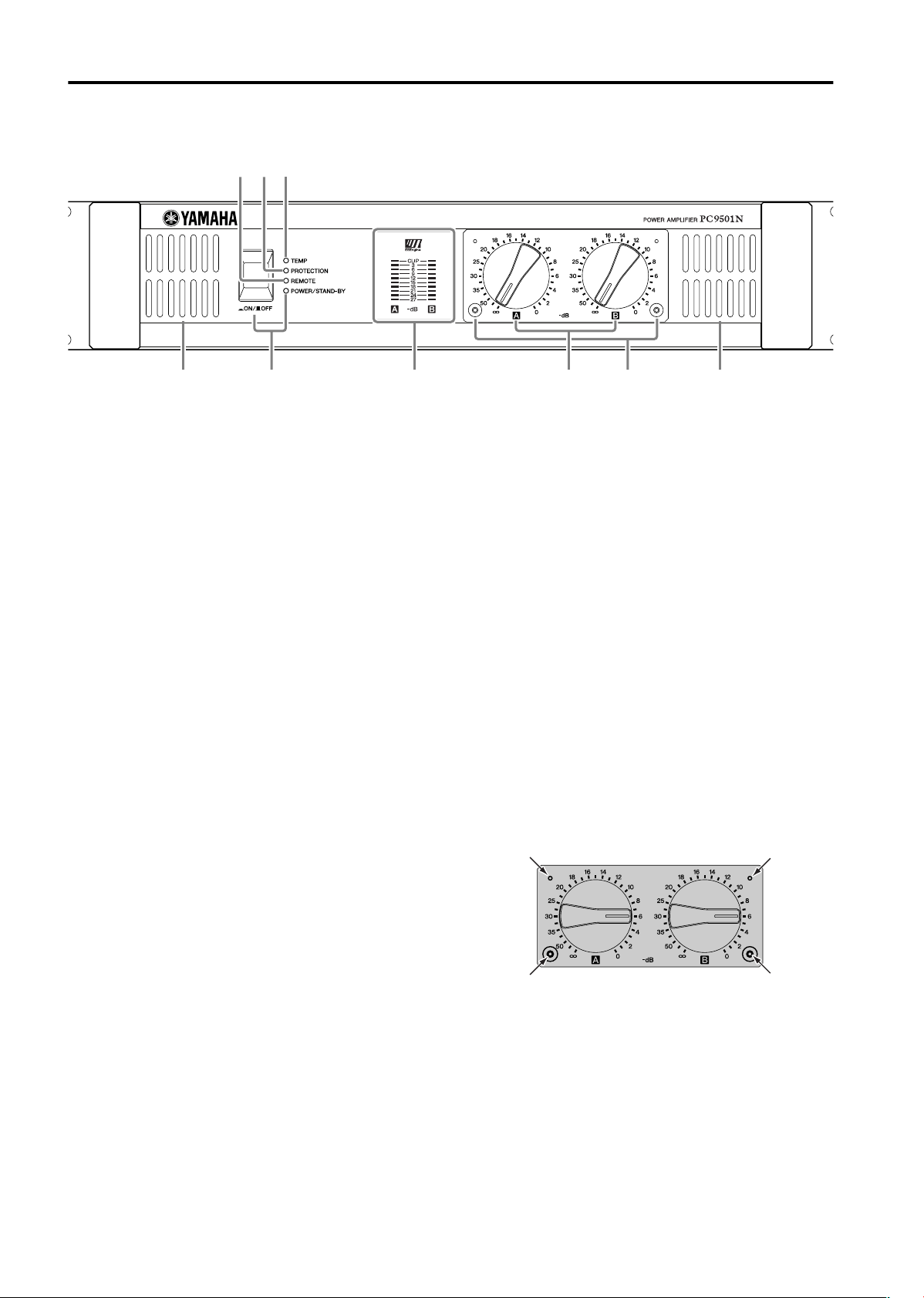
Controls and Functions
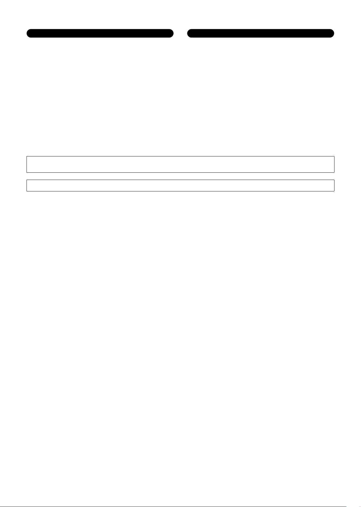
■ Front Panel
1 POWER/STAND-BY switch and indicator
This turns the power of the amplifier on/off. When you
press the switch to turn on the power, the indicator will
light green.
If the amplifier is connected to an amp control unit
ACU16-C and the amplifier has been commanded to
enter STAND-BY mode, this indicator will light orange.
2 REMOTE indicator
This indicator will light green if the amplifier is being
controlled from an external device connected to the
DATA port located on the rear panel.
3 PROTECTION indicator
This indicator lights up red when the protection circuit
is operating. During this time, the amp will be
disconnected from the speaker system, and no sound
will be output from the speaker.
The protection system activates in the following
situations:
• When the amplifier is turned on
The protection system activates for approximately ten
seconds when the amplifier is turned on. After ten
seconds, the protection system deactivates
automatically and the amplifier is ready for normal
operation.
• If a DC voltage is detected at the amplifier’s outputs
Turn off the power, and then turn the power back on
again.
• If the amplifier overheats
When this occurs, the TEMP indicator will be lit.
You should turn off the amplifier and allow it time to
cool down. See the Precautions section of this Owner’s
Manual for ways to prevent the amplifier overheating.
4 TEMP indicator
This indicator will light red if the heat sink temperature
exceeds 85 degrees Celsius.
5 Level meters
These are nine-segment level meters that indicate the
output level of output jacks A and B. If the distortion of
the output signal exceeds 1%, the red CLIP indicator
will light.
6 Volume knobs
These are detented volume knobs that attenuate the
input signals of channels A and B over a range of –∞
– 0 dB.
In BRIDGE mode, only the channel A knob is used.
7 Air intakes
The amplifier has a forced-air cooling fan that takes in
air from the front and exhausts it from the rear. You
must make sure that these intakes are not obstructed.
8 Security cover
If you want to keep the volume settings from being
modified, attach the included security cover using the
screw holes shown below, so that the volume controls
are inaccessible.
1 8
234
5 776
Loading...