


 Loading...
POWER AMPLIFIER
Owner’s Manual
E
Downloaded from: http://www.usersmanualguide.com/
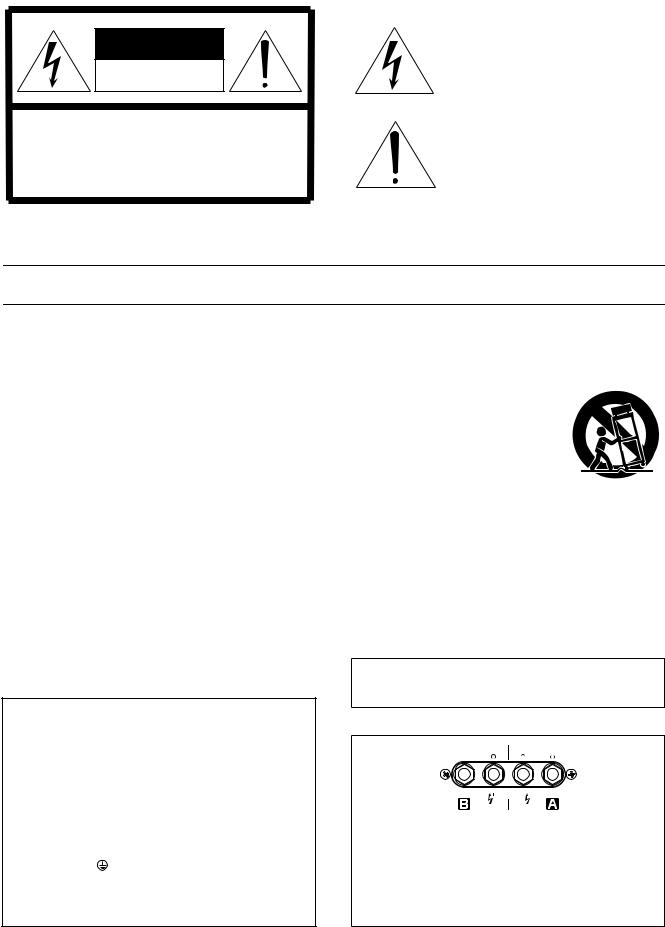
CAUTION
RISK OF ELECTRIC SHOCK
DO NOT OPEN
CAUTION: TO REDUCE THE RISK OF ELECTRIC SHOCK, DO NOT REMOVE COVER (OR BACK). NO USER-SERVICEABLE PARTS INSIDE. REFER SERVICING TO QUALIFIED SERVICE PERSONNEL.
The above warning is located on the top of the unit
• Explanation of Graphical Symbols
The lightning flash with arrowhead symbol within an equilateral triangle is intended to alert the user to the presence of uninsulated Òdangerous voltageÓ within the productÕs enclosure that may be of sufficient magnitude to constitute a risk of electric shock to persons.
The exclamation point within an equilateral triangle is intended to alert the user to the presence of important operating and maintenance (servicing) instructions in the literature accompanying the product.
IMPORTANT SAFETY INSTRUCTIONS
1Read these instructions.
2Keep these instructions.
3Heed all warnings.
4Follow all instructions.
5Do not use this apparatus near water.
6Clean only with dry cloth.
7Do not block any ventilation openings. Install in accordance with the manufacturer’s instructions.
8Do not install near any heat sources such as radiators, heat registers, stoves, or other apparatus (including amplifiers) that produce heat.
9Do not defeat the safety purpose of the polarized or grounding-type plug. A polarized plug has two blades with one wider than the other. A grounding type plug has two blades and a third grounding prong. The wide blade or the third prong are provided for your safety. If the provided plug does not fit into your outlet, consult an electrician for replacement of the obsolete outlet.
10Protect the power cord from being walked on or pinched particularly at plugs, convenience
IMPORTANT NOTICE FOR THE UNITED KINGDOM |
|
Connecting the Plug and Cord |
|
WARNING: THIS APPARATUS MUST BE EARTHED |
|
IMPORTANT. The wires in this mains lead are coloured in accordance |
|
with the following code: |
|
GREEN-AND-YELLOW : EARTH |
|
BLUE |
: NEUTRAL |
BROWN |
: LIVE |
As the colours of the wires in the mains lead of this apparatus may not |
|
correspond with the coloured markings identifying the terminals in |
|
your plug proceed as follows: |
|
The wire which is coloured GREEN-and-YELLOW must be connected |
|
to the terminal in the plug which is marked by the letter E or by the |
|
safety earth symbol |
or colored GREEN or GREEN-and-YELLOW. |
The wire which is coloured BLUE must be connected to the terminal |
|
which is marked with the letter N or coloured BLACK. |
|
The wire which is coloured BROWN must be connected to the termi- |
|
nal which is marked with the letter L or coloured RED. |
|
• This applies only to products distributed by Yamaha-Kemble Music (U.K.) Ltd. (3 wires)
receptacles, and the point where they exit from the apparatus.
11Only use attachments/accessories specified by the manufacturer.
12Use only with the cart, stand, tripod, bracket, or table spec-
ified by the manufacturer, or sold with the apparatus. When a cart is used, use caution when moving the cart/ apparatus combination to avoid injury from tip-over.
13Unplug this apparatus during lightning storms or when unused for long periods of time.
14Refer all servicing to qualified service personnel. Servicing is required when the apparatus has been damaged in any way, such as powersupply cord or plug is damaged, liquid has been spilled or objects have fallen into the apparatus, the apparatus has been exposed to rain or moisture, does not operate normally, or has been dropped.
WARNING
TO REDUCE THE RISK OF FIRE OR ELECTRIC SHOCK,
DO NOT EXPOSE THIS APPARATUS TO RAIN OR MOISTURE.
- |
1 |
+ |
+ |
1 |
- |
|
|
(-) |
(+) |
|
|
|
|
|
BRIDGE |
|
|
This  mark indicates a dangerous electrically live terminal. When connecting an external wire to this terminal, it is necessary either to have “a person who have received appropriate guidance on handling” make the connection or to use leads or a cord that have been manufactured in such a way that the connection can be made simply and without problem.
2
Downloaded from: http://www.usersmanualguide.com/

Precautions
— For safe operation —
 WARNING
Installation
●Connect this unitÕs power cord only to an AC outlet of the type stated in this OwnerÕs Manual or as marked on the unit. Failure to do so is a Þre and electrical shock hazard.
●Do not allow water to enter this unit or allow the unit to become wet. Fire or electrical shock may result.
●Do not place a container with liquid or small metal objects on top of this unit. Liquid or metal objects inside this unit are a Þre and electrical shock hazard.
●Do not place heavy objects, including this unit, on top of the power cord. A damaged power cord is a Þre and electrical shock hazard. In particular, be careful not to place heavy objects on a power cord covered by a carpet.
Operation
●Do not scratch, bend, twist, pull, or heat the power cord. A damaged power cord is a Þre and electrical shock hazard.
●Do not remove the unitÕs cover. You could receive an electrical shock. If you think internal inspection, maintenance, or repair is necessary, contact your dealer.
●Do not modify the unit. Doing so is a Þre and electrical shock hazard.
●If lightning begins to occur, turn off the power switch of the unit as soon as possible, and unplug the power cable plug from the electrical outlet.
●If there is a possibility of lightning, do not touch the power cable plug if it is still connected. Doing so may be an electrical shock hazard.
In case an abnormality occurs during operation
●If the power cord is damaged (i.e., cut or a bare wire is exposed), ask your dealer for a replacement. Using the unit with a damaged power cord is a Þre and electrical shock hazard.
●Should this unit be dropped or the cabinet be damaged, turn the power switch off, remove the power plug from the AC outlet, and contact your dealer. If you continue using the unit without heeding this instruction, Þre or electrical shock may result.
●If you notice any abnormality, such as smoke, odor, or noise, or if a foreign object or liquid gets inside the unit, turn it off immediately. Remove the power cord from the AC outlet. Consult your dealer for repair. Using the unit in this condition is a Þre and electrical shock hazard.
 CAUTION
Installation
●Keep this unit away from the following locations:
-Locations exposed to oil splashes or steam, such as near cooking stoves, humidiÞers, etc.
-Unstable surfaces, such as a wobbly table or slope.
-Locations exposed to excessive heat, such as inside a car with all the windows closed, or places that receive direct sunlight.
-Locations subject to excessive humidity or dust accumulation.
●Do not place the power cord close to a heater. It may melt, causing Þre or electrical shock.
●Hold the power cord plug when disconnecting it from an AC outlet. Never pull the cord. A damaged power cord is a potential Þre and electrical shock hazard.
●Do not touch the power plug with wet hands. Doing so is a potential electrical shock hazard.
●This unit has ventilation holes at the front and rear to prevent the internal temperature rising too high. Do not block them. Blocked ventilation holes are a Þre hazard.
In particular, do not
-place the unit on its side or upside down,
-place the unit in any poorly-ventilated location such as a bookcase or closet (other than on the dedicated rack),
-cover the unit with a table cloth or place it on a carpet or bed.
●Allow enough free space around the unit for normal ventilation. This should be: 5 cm at the sides, 10 cm behind, and 10 cm above.
If the airßow is not adequate, the unit will heat up inside and may cause a Þre.
●To mount several of these units in a standard EIA rack, refer to the rack mounting instructions on page 11.
●To relocate the unit, turn the power switch off, remove the power plug from the AC outlet, and remove all connecting cables. Damaged cables may cause Þre or electrical shock.
Operation
●Use only speaker cables when connecting speakers to ampliÞer outputs. Using other types of cables is a Þre hazard.
●Turn off all musical instruments, audio equipment, and speakers when connecting to this unit. Use the correct connecting cables and connect as speciÞed.
●Always lower the volume control to minimum before turning on the power to this unit. A sudden blast of sound may damage your hearing.
●Do not use this ampliÞer for any purpose other than driving loudspeakers.
●If you know you will not use this unit for a long period of time, such as when going on vacation, remove the power plug from the AC outlet. Leaving it connected is a potential Þre hazard.
3
Downloaded from: http://www.usersmanualguide.com/

— For correct operation —
Connector pin assignments |
|
Interference from Cell Phones |
|
|
|
● XLR-type connectors are wired as follows |
|
● Use of a mobile phone near this unit may induce noise. If noise |
Pin 1: ground; Pin 2: hot (+); Pin 3: cold (Ð). |
|
occurs, move the phone further from the unit. |
Always turn the power off when the ampliÞer is not in use.
Illustrations in this manual are for explanatory purposes only, and may not match the actual appearance of the product during operation. Company names and product names used in this Owner's Manual are trademarks or registered trademarks of their respective owners.
FCC INFORMATION (U.S.A.)
1.IMPORTANT NOTICE: DO NOT MODIFY THIS UNIT!
This product, when installed as indicated in the instructions contained in this manual, meets FCC requirements. ModiÞcations not expressly approved by Yamaha may void your authority, granted by the FCC, to use the product.
2.IMPORTANT: When connecting this product to accessories and/or another product use only high quality shielded cables. Cable/s supplied with this product MUST be used. Follow all installation instructions. Failure to follow instructions could void your FCC authorization to use this product in the USA.
* This applies only to products (P7000S, P5000S) distributed by YAMAHA CORPORATION OF AMERICA.
4
Downloaded from: http://www.usersmanualguide.com/

Introduction
Thank you for your purchase of the YAMAHA P7000S, P5000S, P3500S or P2500S power ampliÞer. These P-series ampliÞers fully incorporate YamahaÕs renown technological expertise, and offer high reliability, rock-solid stability, and superb acoustic characteristicsÑall in a trim, 2U-sized package.
FEATURES
¥With two types of input jacks (balanced XLR and balanced phone) and three types of output jacks (Speakon, 5-way binding post, and phone), the P series is suitable for a wide variety of applications and installed systems.
¥The unit offers three operating modes: STEREO (where Channels A and B operate independently), PARALLEL (where the unit outputs a mono source through twin ampliÞer systems), and BRIDGE (where the unit operates as a single high-power amp).
¥Each channel is equipped with an independent OFF/LOW CUT/SUBWOOFER switchÑwhere LOW CUT engages a high-pass Þlter, and SUBWOOFER engages a low-pass Þlter. With LOW CUT or SUBWOOFER selected, you can adjust the cutoff frequency from 25 to 150 Hz.
¥Each channel has its own SIGNAL and CLIP indicators.
¥The PROTECTION indicator lights upÑand sound output is automatically mutedÑwhenever the unitÕs protective circuitry is operating. The TEMP indicator lights up if the unit is running hot.
¥Variable-speed low-noise fans ensure high reliability.
This OwnerÕs Manual covers the four models: P7000S, P5000S, P3500S and P2500S power ampliÞers. Please read through this manual carefully before beginning use, so that you will be able to take full advantage of the ampliÞerÕs superlative features and enjoy trouble-free operation for years to come. After reading through the manual, please store it in a safe place.
Contents |
|
Controls and Functions |
..................................... 6 |
Front Panel .......................................................... |
6 |
Rear Panel ........................................................... |
7 |
Speaker Connections ........................................ |
9 |
Speaker impedance ............................................. |
9 |
Wiring ................................................................ |
10 |
Rack Mounting ................................................ |
11 |
SpeciÞcations .................................................. |
12 |
General Specifications ....................................... |
12 |
Block Diagram ................................................... |
13 |
Dimensions ........................................................ |
14 |
Performance Graphs ......................................... |
14 |
Troubleshooting ............................................... |
15 |
5
Downloaded from: http://www.usersmanualguide.com/
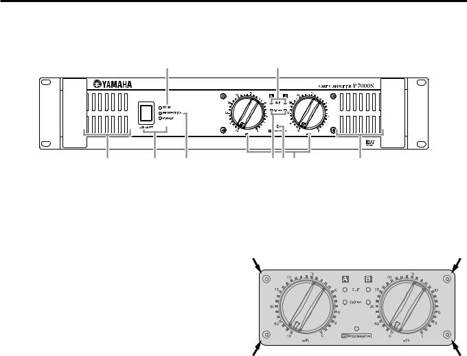
Controls and Functions
■ Front Panel
2
8 |
1 |
3 |
4 |
576 |
8 |
1POWER switch and indicator
Press to toggle the power on or off. The POWER indicator lights up green when the power is ON.
2TEMP indicator
Lights up red if the heat sink temperature exceeds 85¡C (185¡F).
3PROTECTION indicator
Lights up red to indicate that protection is in effect. SpeciÞcally, lights up if the heat sink overheats, or if a DC voltage is detected at the ampliÞer outputs. Also lights up for about three seconds at time of power-on, as the amp gets ready to operate. To provide protection, the unit will not output any sound from the speakers while this indicator is lit up. When start-up is completed or the problem is corrected, the indicator goes off and normal operation resumes.
4CLIP indicator
Lights up red when the output signal distortion on the corresponding channel rises above 1%Ñindicating that ÒclippingÓ has occurred because the signal level is too high.
5SIGNAL indicator
Lights up green when the corresponding channelÕs output level exceeds 2 Vrms (equivalent to 1/2 W into an 8 Ω load, or 1 W into a 4 Ω load).
6Volume control knobs
Each control knob adjusts the volume of the corresponding channel, in 31 steps from Ð∞ dB to 0 dB.
NOTE:
If you wish to lock in the knob settings, you can fasten the supplied security cover over the knobs so that the settings will not be disturbed.
How to install the security cover
(1)Use the supplied hex wrench to remove the four attachment screws from the ampliÞer.
(2)Adjust the security cover to the position of screw holes. Fasten it into place using the same screws.
7  indicator
Lights up yellow if the YS PROCESSING switch on the rear panel is set ON. (See page 7.)
8Air intakes
The ampliÞer uses forced-air cooling. The cooling fans draw air in from the front and exhaust it through the rear. Please be sure that you do not block the air intakes or exhaust vents.
NOTE:
The fans do not come on at initial power-on, but will switch on automatically when the temperature of the heat sink rises above 50¡C (122¡F). The fan speed will then vary automatically as the temperature changes.
6
Downloaded from: http://www.usersmanualguide.com/
Loading...