


Multitrack Cassette Recorder
User’s Guide
Manuel de l’utilisateur
Bedienungsanleitung
Guía del Usuario
|
1 |
|
2 |
|
3 |
4 |
|
|
MASTER |
|
|
|
|
|
|
|
|
|
|
|
|
|
MIC/LINE |
MIC/LINE |
MIC/LINE |
MIC/LINE |
|
|
|
|
|
|
|
|
|
|
|
|
|
|
|
||||
GAIN |
|
GAIN |
|
GAIN |
|
GAIN |
|
|
AUX RETURN |
|
|
|
|
|
|
|
|
|
|
|
|
|
|
|
|
|
|
|
|
|
|
1 |
|
2 |
|
|
|
|
|
|
|
|
|
|
|
|
|
|
|
|
|
|
|
1 |
2 |
1 |
2 |
|
|
|
|
|
|
|
|
|
|
|
LINE |
MIC |
LINE |
MIC |
LINE |
MIC |
LINE |
MIC |
ASSIGN |
ASSIGN |
|
|
|
|
|
|
|
|
|
|
|
||
HIGH |
|
HIGH |
|
HIGH |
|
HIGH |
|
|
|
|
|
|
|
|
|
|
|
|
|
|
|
|
|
|
|
|
|
|
|
|
3 |
4 |
3 |
4 |
|
|
|
|
|
|
|
|
|
|
|
|
|
|
|
|
|
|
|
|
LEVEL |
|
|
|
|
|
|
|
|
|
|
|
|
|
-12 |
+12 |
-12 |
+12 |
-12 |
+12 |
-12 |
+12 |
|
|
|
|
|
|
|
|
|
|
|
|
|
|
|
MID |
|
MID |
|
MID |
|
MID |
|
|
|
|
|
|
|
|
|
|
|
|
|
|
|
|
|
|
|
|
|
|
|
|
0 |
10 |
0 |
10 |
|
|
|
|
|
|
|
|
|
|
|
-12 |
+12 |
-12 |
+12 |
-12 |
+12 |
-12 |
+12 |
|
|
|
|
|
|
|
|
|
|
|
|
|
|
|
LOW |
|
LOW |
|
LOW |
|
LOW |
|
|
|
CUE LEVEL |
|
|
|
|
|
|
|
|
|
|
|
|
|
|
|
|
|
|
|
|
|
|
|
|
|
|
|
|
|
|
|
|
|
||
|
|
|
|
|
|
|
|
MONITOR |
1 |
|
|
|
|
|
|
|
|
|
|
|
|
|
|
|
|
|
|
|
|
|
SELECT |
|
|
|
|
|
|
|
|
|
|
|
|
|
|
-12 |
+12 |
-12 |
+12 |
-12 |
+12 |
-12 |
+12 |
|
|
|
|
|
|
|
|
|
|
|
|
|
|
|
AUX |
|
AUX |
|
AUX |
|
AUX |
|
1 |
3 |
|
|
|
|
|
|
|
|
|
|
|
|
|
|
|
|
|
|
|
|
|
|
GROUP |
0 |
10 |
|
|
|
|
|
|
|
|
|
|
|
|
|
|
|
|
|
|
|
|
2 |
|
|
|
|
|
|
|
|
|
|
|
|
|
|
|
|
|
|
|
|
|
2 |
4 |
|
|
|
|
|
|
|
|
|
|
|
|
|
AUX 1 |
AUX 2 |
AUX 1 |
AUX 2 |
AUX 1 |
AUX 2 |
AUX 1 |
AUX 2 |
STEREO |
|
|
|
|
|
|
|
|
|
|
|
|
|
|
|
|
|
|
|
|
|
|
|
|
|
|
|
|
|
|
|
|
|
|
|
||
1 |
2 |
1 |
2 |
1 |
2 |
1 |
2 |
|
|
0 |
10 |
|
|
|
|
+9 |
|
|
|
|
+9 |
|
|
|
3 |
|
|
TAPE |
|
|
|
|
|
|
|
||||||||||
|
|
|
|
|
|
|
|
|
|
|
|
|
|
|
6 |
|
|
|
|
6 |
|
|
ASSIGN |
ASSIGN |
ASSIGN |
ASSIGN |
|
CUE |
|
|
|
|
|
|
3 |
|
|
|
|
3 |
|
||||
|
|
|
|
9.5 4.8 |
|
|
0 |
|
|
|
|
0 |
|
|||||||||
3 |
4 |
3 |
4 |
3 |
4 |
3 |
4 |
|
|
|
|
|
|
|
|
3 |
|
|
|
|
3 |
|
|
|
|
|
|
|
|
|
6 |
|
|
|
|
6 |
|
||||||||
|
|
|
|
|
|
|
|
|
|
|
|
|
AUTO PUNCH |
|
1 |
10 |
|
|
|
|
10 |
|
|
C |
|
C |
|
C |
C |
|
|
|
0 |
10 |
|
|
MEMO |
REPEAT |
-20 |
|
|
|
|
-20 |
|
PAN |
PAN |
PAN |
|
MONITOR/PHONES |
|
SYNC START IN OUT |
|
2 |
REC |
1 |
2 |
3 |
4 |
L |
R |
|||||||
|
|
|
PAN |
|
|
|
|
|||||||||||||||
|
|
|
|
|
|
|
|
|
|
4 |
|
|
|
|
|
|
1 |
2 |
3 |
4 |
STEREO |
|
|
|
|
|
|
|
|
|
|
|
|
|
NOISE REDUCTION SYSTEM |
|
|
|
|||||||
|
|
|
|
|
|
|
|
|
|
|
|
|
|
|
|
TRACK |
|
|
|
|||
L |
R |
L |
R |
L |
R |
L |
R |
MIN |
MAX |
0 |
10 |
TAPE SPEED CONTROL |
|
|
|
|
REC SELECT |
|
||||
PITCH |
|
|
|
|
|
|
|
|
|
|
||||||||||||
ODD |
EVEN |
ODD |
EVEN |
ODD |
EVEN |
ODD |
EVEN |
|
|
|
|
|
|
|
|
|
|
|
|
|
|
|
TAPE |
MIC/ |
TAPE |
MIC/ |
TAPE |
MIC/ |
TAPE |
MIC/ |
|
|
|
|
|
4.8 / 9.5 |
|
|
|
|
|
|
|
|
|
|
LINE |
|
LINE |
|
LINE |
|
LINE |
|
|
|
|
O |
|
|
1 |
|
|
2 |
|
|
3 |
4 |
|
|
|
|
|
|
|
|
|
|
|
|
|
|
|
|
|
|
|||||
|
|
|
|
|
|
|
|
|
|
|
|
|
|
|
|
|
|
|
|
|
RETURN |
|
|
|
|
|
|
|
|
|
|
|
|
|
|
|
|
|
|
REPEAT |
|
|
TO ZERO |
|
|
10 |
|
10 |
|
10 |
|
10 |
|
|
10 |
|
10 |
|
|
|
|
|
|
|
|
|
|
|
9 |
|
9 |
|
9 |
|
9 |
|
|
9 |
|
9 |
|
|
|
|
|
|
|
|
|
|
|
8 |
|
8 |
|
8 |
|
8 |
|
|
8 |
|
8 |
|
AUTO |
|
|
|
|
|
|
|
|
COUNTER |
7 |
|
7 |
|
7 |
|
7 |
|
|
7 |
|
7 |
|
PUNCH I/O |
CHECK |
|
MEMO 1 |
|
LOCATE |
RESET |
|||
6 |
|
6 |
|
6 |
|
6 |
|
|
6 |
|
6 |
|
|
|
|
|
|
|
|
|
|
|
5 |
|
5 |
|
5 |
|
5 |
|
|
5 |
|
5 |
|
|
|
|
|
|
|
|
|
|
|
4 |
|
4 |
|
4 |
|
4 |
|
|
4 |
|
4 |
|
|
|
|
|
|
|
|
|
|
|
3 |
|
3 |
|
3 |
|
3 |
|
|
3 |
|
3 |
SYNC |
CLEAR |
|
|
|
MEMO 2 |
|
|
LOCATE |
|
|
2 |
|
2 |
|
2 |
|
2 |
|
|
2 |
|
2 |
|
|
|
|
|
|
|
|
|
|
|
1 |
|
1 |
|
1 |
|
1 |
|
|
1 |
|
1 |
|
|
|
|
|
|
|
|
|
|
|
0 |
|
0 |
|
0 |
|
0 |
|
|
0 |
|
0 |
|
|
|
|
|
|
|
|
|
|
|
|
|
|
|
|
|
|
|
|
|
|
|
REHE |
REC/PAUSE |
|
PLAY |
|
|
REW |
|
|
FF |
STOP |
|
|
MULTITRACK CASSETTE RECORDER |
|
|
|
PHONES |
|
PUNCH I/O |
|
|
|
|
|
|
|
|
|
|
|
|||
Downloaded from: http://www.usersmanualguide.com/

FCC INFORMATION (U.S.A.)
1.IMPORTANT NOTICE: DO NOT MODIFY THIS UNIT!
This product, when installed as indicated in the instructions contained in this manual, meets FCC requirements. Modifications not expressly approved by Yamaha may void your authority, granted by the FCC, to use the product.
2.IMPORTANT: When connecting this product to accessories and/or another product use only high quality shielded cables. Cable/s supplied with this product MUST be used. Follow all installation instructions. Failure to follow instructions could void your FCC authorization to use this product in the USA.
3.NOTE: This product has been tested and found to comply with the requirements listed in FCC Regulations, Part 15 for Class “B” digital devices. Compliance with these requirements provides a reasonable level of assurance that your use of this product in a residential environment will not result in harmful interference with other electronic devices. This equipment generates/uses radio frequencies and, if not installed and used according to the instructions found in the users manual, may cause interference harmful to the operation of other electronic devices. Compliance with FCC regulations does not guarantee that interference will not occur in all installations. If this product is found to be the source of interference, which can be determined by turning the unit “OFF” and “ON”, please try to eliminate the problem by using one of the following measures:
Relocate either this product or the device that is being affected by the interference.
Utilize power outlets that are on different branch (circuit breaker of fuse) circuits or install AC line filter/s.
In the case of radio or TV interference, relocate/reorient the antenna. If the antenna lead-in is 300 ohm ribbon lead, change the lead-in to coaxial type cable.
If these corrective measures do not produce satisfactory results, please contact the local retailer authorized to distribute this type of product. If you can not locate the appropriate retailer, please contact Yamaha Corporation of America, Electronic Service Division, 6600 Orangethorpe Ave, Buena Park, CA 90620
*This applies only to products distributed by YAMAHA CORPORATION OF AMERICA.
IMPORTANT NOTICE FOR
THE UNITED KINGDOM
Connecting the Plug and Cord
IMPORTANT: The wires in this mains lead are coloured in accordance with the following code:
BLUE : NEUTRAL
BROWN : LIVE
As the colours of the wires in the mains lead of this apparatus may not correspond with the coloured markings identifying the terminals in your plug proceed as follows:
The wire which is coloured BLUE must be connected to the terminal which is marked with the letter N or coloured BLACK.
The wire which is coloured BROWN must be connected to the terminal which is marked with the letter L or coloured RED.
Making sure that neither core is connected to the earth terminal of the three pin plug.
*This applies only to products distributed by YAMAHA - KEMBLE MUSIC (U.K.) LTD.
Dette apparat overholder det gaeldende EF-direktiv vedrørende radiostøj.
Cet appareil est conforme aux prescriptions de la directive communautaire 87/308/CEE.
Diese Geräe entsprechen der EG-Richtlinie 82/499/EWG und/oder 87/308/EWG.
This product complies with the radio frequency interference requirements of the Council Directive 82/499/EEC and/or 87/308/EEC.
Questo apparecchio é conforme al D.M.13 aprile 1989 (Direttiva CEE/87/308) sulla soppressione dei radiodisturbi.
Este producto está de acuerdo con los requisitos sobre interferencias de radio frequencia fijados por el Consejo Directivo 87/308/CEE.
YAMAHA CORPORATION
CANADA
THIS DIGITAL APPARATUS DOES NOT EXCEED THE “CLASS B” LIMITS FOR RADIO NOISE EMISSIONS FROM DIGITAL APPARATUS SET OUT IN THE RADIO INTERFERENCE REGULATION OF THE CANADIAN DEPARTMENT OF COMMUNICATIONS.
LE PRESENT APPAREIL NUMERIQUE N’EMET PAS DE BRUITS RADIOELECTRIQUES DEPASSANT LES LIMITES APPLICABLES AUX APPAREILS NUMERIQUES DE LA “CLASSE B” PRESCRITES DANS LE REGLEMENT SUR LE BROUILLAGE RADIOELECTRIQUE EDICTE PAR LE MINISTERE DES COMMUNICATIONS DU CANADA.
*This applies only to products distributed by YAMAHA CANADA MUSIC LTD.
Downloaded from: http://www.usersmanualguide.com/

1 |
Precautions |
Precautions
1Avoid excessive heat, humidity, dust, and vibration.
Keep the MT4X away from locations where it is likely to be exposed to high temperatures or humidity, such as direct sunlight, near radiators, stoves, etc. Also avoid locations which are subject to excessive dust accumulation or vibration which could cause mechanical damage.
2Avoid physical shocks
Strong physical shocks can cause damage. Handle the unit with care.
3Clean with a soft dry cloth
Never use solvents such as benzine or thinner to clean the MT4X. Wipe it clean with a soft dry cloth.
4Do not open the case or attempt repairs or modiÞcation yourself
The MT4X contains no user-serviceable parts. For other than routine cleaning, refer all maintenance to qualiÞed YAMAHA service personnel. Opening the case and/or tampering with the internal circuitry will void the warranty.
5Make sure power is off before making or removing connections
Always turn the power OFF prior to connecting or disconnecting cables. This will prevent damage to the MT4X as well as other connected equipment.
6Handle cables carefully
Always plug and unplug cables Ñ including the AC cord Ñ by gripping the connector, not the cord.
7Always use the correct power supply
The MT4X is sold conÞgured to the appropriate power speciÞcations for the local area. The power supply voltage and power consumption are listed on the bottom panel. If you move
Contents
Precautions1
Introduction2
Features2
Structure of the MT4X3
1Controls and Connections5 Channel Modules6
Master Module7 Recorder Controls8 Transport Controls10 Multi-function Display10
Front Panel Connections11 Rear Panel Connections12 Power Connections13
2 Example System14
3Recording Functions15 Monitoring15
Initial recording16 Overdubbing19
to an area with a different AC mains voltage, be sure to check with your nearest YAMAHA dealer before using the unit.
8Keep the heads and tape path clean
To ensure consistent high performance and sound quality from the MT4X, it is important to clean the heads and tape path regularly Ñ ideally before each recording session. Use a cleaning kit speciÞcally designed to use with cassette tape equipment.
9Use only high-quality chrome cassette tape
The MT4X is designed to be used with Chrome tape (CrO2 tape Ñ Bias: HIGH or TYPEII position; EQ: 70μs). It will not work properly with Ferrichrome tape formulations. You may experience high frequency distortion if you use such tapes.
The use of tapes longer than 90 minutes (C-120 and longer) is not recommended. These tapes are much thinner and therefore prone to poor performance or failure.
TDK SA 46 Ð 90 and Maxell XLII 46 Ð 90 are recommended.
10Handle the cassette tapes properly
You should fast forward and rewind new tapes before you record on them. This will prevent any possible binding that could be caused by the tape being tightly wound at the factory. It is best not to use the Þrst and last 20 seconds of a tape. The splice between the leader and the tape can cause distortion. When loading a cassette, check that the tape is not loose, then load the tape Þrmly into the cassette compartment. If the tape is not loaded properly, the unit may jam or otherwise malfunction.
11Use the dbxª switch correctly
To obtain the best possible sound quality, you should always use the dbxª noise reduction system to playback tapes that were recorded with the dbxª system on. If the tape was recorded without dbxª, turn the noise reduction system off.
The dbxª noise reduction system was manufactured based on a patent licence from THAT Corporation. dbx is a trademark of Carillion Electronics Corporation.
Punch-in/out recording21
Ping-pong recording29
Mixdown32
4Synchronization34 FSK recording35 Synchronized playback36 Synchronized mixdown39
5Memory Functions41 Memo Function41 Repeat Function42
Recording Levels Function42
Appendix44
Troubleshooting44
Maintenance45
Specifications46
Block Diagram48
Dimensions49
Tracking Sheet49
Glossary51
UserÕs Guide
Downloaded from: http://www.usersmanualguide.com/

Introduction |
2 |
Introduction
Your MT4X Multitrack Cassette recorder is a powerful recording tool that will allow you to capture your music at a very high level of sound quality. It is an advanced technology, easy-to-use four-track cassette tape recorder with a comprehensive four-channel mixer.
In order to make use of the many features of the MT4X and to obtain the best performance, please read this manual thoroughly Ñ and keep it in a safe place for future reference.
Features
General
The MT4X consists of a four-channel mixer section and a four-track cassette tape recorder section inside a compact enclosure. Independent recording and playback is possible for each track. This allows you to create high-quality multi-track recordings.
Mixer
¥The mixer section is equipped with independent stereo buses for greater ßexibility.
¥Continuously variable gain controls are provided for each input channel. These can be used with any input source, from microphones to electronic instruments.
¥Each channel has a three band equalizer (HIGH, MID, and LOW) giving you ßexible tone-shaping capabilities.
¥Dual AUX SEND and AUX RETURN (stereo) connectors allow you to add effects from external signal processors. You can assign the AUX RETURN signal to each channel as required.
Recorder
¥The dbx™ noise reduction system provides substantial noise reduction and a wide dynamic range.
¥An automatic punch-in/out recording function and a rehearsal function make recording easier and more accurate. Locate functions, such as memory and return-to-zero are provided for additional convenience.
¥A large, multi-functional display shows the recording and playback levels, along with a tape counter and other indicators, giving you immediate and helpful information about the status of the MT4X.
¥The pitch control allows you to vary the tape speed with in a range of approximately ±10%. This can be useful when you have to compensate for pitch variations during an overdub.
¥The tape transport is a full-logic mechanism, making recording and playback operation smooth and simple.
¥The transport offers two speeds: 9.5 cm/sec and 4.8 cm/sec.
UserÕs Guide
Downloaded from: http://www.usersmanualguide.com/
com/.usersmanualguide.http://www from: Downloaded
Guide UserÕs
|
MONITOR OUT |
|
STEREO OUT |
|
TAPE OUT |
|
|||
|
R |
L |
AUX RETURN |
R |
L |
SYNC/4 |
3 |
2 |
1 |
MIC/LINE INPUT |
AUX SEND |
|
|
|
|
|
|
|
|
2 |
1 |
2 |
|
1 |
|
|
|
|
|
|
|
|
|
|
|
|
|
||
|
|
|
L/MONO |
L/MONO |
|
|
|
|
|
|
3 |
|
|
MASTER |
|
|
|
|
|
MIC/LINE |
|
|
|
|
|
|
|
||
GAIN |
|
|
|
AUX RETURN |
|
|
|
|
|
|
|
|
|
|
|
|
|
||
|
|
|
|
1 |
|
2 |
|
|
|
|
|
|
1 |
2 |
1 |
2 |
|
|
|
LINE |
0 |
MIC |
ASSIGN |
ASSIGN |
|
|
|
||
HIGH |
|
|
|
|
|||||
|
|
|
|
|
|
|
|
|
|
|
|
|
3 |
4 |
3 |
4 |
|
|
|
|
|
|
|
LEVEL |
|
|
|
|
|
-12 |
0 |
+12 |
|
|
|
|
|
|
|
MID |
|
|
|
|
|
|
|
|
|
|
|
|
|
|
|
|
|
|
|
|
|
|
0 |
10 |
0 |
10 |
|
|
|
-12 |
0 |
+12 |
|
|
|
|
|
|
|
LOW |
|
|
|
|
|
|
|
|
|
|
|
|
|
CUE LEVEL |
|
|
|
||
|
|
|
|
|
|
|
|
||
|
|
|
MONITOR |
1 |
|
|
|
|
|
|
|
|
SELECT |
|
|
|
|
|
|
-12 |
|
+12 |
|
|
|
|
|
|
|
AUX |
|
|
1 |
3 |
0 |
10 |
|
|
|
|
|
|
|
GROUP |
|
|
|
||
|
|
|
|
2 |
|
|
|
|
|
|
|
|
|
|
|
|
|
|
|
|
|
|
2 |
4 |
|
|
|
|
|
AUX 1 |
|
AUX 2 |
STEREO |
|
|
|
|
|
|
|
|
|
|
|
|
|
|
||
1 |
|
2 |
|
|
0 |
10 |
|
REC SELECT |
|
|
|
|
3 |
|
|
|
|
||
ASSIGN |
|
|
|
|
|
|
|||
|
CUE |
|
|
|
|
|
|||
|
|
|
|
|
|
|
|
|
|
3 |
|
4 |
|
|
|
1 |
2 |
3 |
4 |
|
C |
|
|
|
|
||||
PAN |
|
MONITOR/PHONES |
0 |
10 |
|
|
|
||
|
|
|
|
|
|||||
|
|
|
|
|
4 |
|
|
|
|
L |
|
R |
MIN |
MAX |
0 |
10 |
|
|
|
ODD |
|
EVEN |
|
|
|
|
|
|
|
TAPE |
MIC/ |
|
LINE |
10 |
10 |
10 |
9 |
9 |
9 |
8 |
8 |
8 |
7 |
7 |
7 |
6 |
6 |
6 |
5 |
5 |
5 |
4 |
4 |
4 |
3 |
3 |
3 |
2 |
2 |
2 |
1 |
1 |
1 |
0 |
0 |
0 |
PHONES
MT4X the of Structure |
Introduction 3 |
|
|

Introduction |
4 |
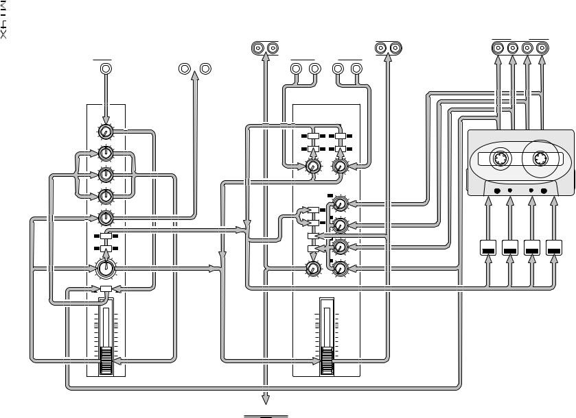
Structure of the MT4X
The MT4X can be divided into three basic sections Ð the mixer, the recorder, and the bus lines which connect them:
Mixer
The mixer has four input channels. It adjusts the input signals at each respective channel and sends them to the bus lines.
The signals input to each channel of the mixer can be switched to either input signals (MIC/LINE) or playback signals (TAPE). When TAPE is selected, the playback signal from each track is input to the corresponding channel. The tone of the signal is adjusted through the equalizer and the volume at the channel faders. It is then sent to the bus lines using the ASSIGN keys and PAN control.
Bus Lines
There are four main bus lines (group buses) which receive the input signals from each respective channel of the mixer. If signals from two or more input channels are sent to a bus line, these signals are overlaid or mixed.
There is also a STEREO bus (L, R), an AUX bus (1, 2), and a CUE bus.
Recorder
The signals from the bus lines are recorded by the cassette recorder. It also sends the signal to the TAPE OUT connectors and back to the mixer (including the CUE bus).
Also refer to the "Block Diagram" on page 48.
UserÕs Guide
Downloaded from: http://www.usersmanualguide.com/

5 |
Controls and Connections |
1Controls and Connections
Power Connections
|
|
|
|
|
|
|
|
|
|
|
|
|
|
|
|
|
ONOFF |
ACIN |
|
|
|
|
|
|
|
|
|
|
|
|
|
|
|
|
|
POWER |
|
|
|
1 |
2 |
|
3 |
SYNC/4 |
1 |
|
2 |
|
L/MONO |
R |
L/MONO |
|
R |
|
|
|
|
|
|
|
|
|
|
|
|
|
|
|
1 |
|
|
2 |
|
|
|
|
|
|
TAPEOUT |
|
|
|
AUXSEND |
|
|
|
AUXRETURN |
|
|
|
|
|
||
|
|
1 |
|
|
2 |
|
|
3 |
|
|
4 |
L |
R |
L |
|
R |
|
|
|
|
|
|
|
|
MIC/LINEINPUT |
|
|
|
|
STEREOOUT |
MONITOROUT |
|
|
||||
|
|
|
|
Rear Panel Connections |
|
|
|
|
|
|||||||||
|
|
Channel Modules |
|
Master Module |
Recorder Controls |
|||||||||||||
|
1 |
|
|
2 |
|
|
3 |
|
|
4 |
|
|
MASTER |
|
|
|
||
MIC/LINE |
MIC/LINE |
MIC/LINE |
MIC/LINE |
|
|
|
|
|
|
|
||||||||
GAIN |
|
|
GAIN |
|
|
GAIN |
|
|
GAIN |
|
|
|
AUX RETURN |
|
|
|
||
|
|
|
|
|
|
|
|
|
|
|
|
1 |
|
|
|
2 |
|
|
|
|
|
|
|
|
|
|
|
|
|
|
1 |
2 |
1 |
|
2 |
|
|
LINE |
0 |
MIC |
LINE |
0 |
MIC |
LINE |
0 |
MIC |
LINE |
0 |
MIC |
ASSIGN |
|
ASSIGN |
|
|
||
HIGH |
|
HIGH |
|
HIGH |
|
HIGH |
|
|
|
|
||||||||
|
|
|
|
|
|
|
|
|
|
|
|
|
|
|
||||
|
|
|
|
|
|
|
|
|
|
|
|
3 |
4 |
3 |
|
4 |
|
|
|
|
|
|
|
|
|
|
|
|
|
|
|
LEVEL |
|
|
|
|
|
-12 |
0 |
+12 |
-12 |
0 |
+12 |
-12 |
0 |
+12 |
-12 |
0 |
+12 |
|
|
|
|
|
|
|
MID |
|
MID |
|
MID |
|
MID |
|
|
|
|
|
|
|
|
||||
|
|
|
|
|
|
|
|
|
|
|
|
|
|
|
||||
|
|
|
|
|
|
|
|
|
|
|
|
0 |
10 |
|
0 |
10 |
|
|
-12 |
0 |
+12 |
-12 |
0 |
+12 |
-12 |
0 |
+12 |
-12 |
0 |
+12 |
|
|
LOW |
|
LOW |
|
LOW |
|
LOW |
|
|
|
||||
|
|
|
|
|
|
|
|
CUE LEVEL |
|||||
|
|
|
|
|
|
|
|
|
|
|
|
||
|
|
|
|
|
|
|
|
|
|
|
MONITOR |
1 |
|
|
|
|
|
|
|
|
|
|
|
|
SELECT |
|
|
-12 |
|
+12 |
-12 |
|
+12 |
-12 |
|
+12 |
-12 |
|
+12 |
|
|
AUX |
|
|
AUX |
|
|
AUX |
|
|
AUX |
|
1 |
3 |
|
|
|
|
|
|
|
|
|
|
|
|
GROUP |
0 |
10 |
|
|
|
|
|
|
|
|
|
|
|
2 |
|
|
|
|
|
|
|
|
|
|
|
|
|
2 |
4 |
|
AUX 1 |
|
AUX 2 |
AUX 1 |
|
AUX 2 |
AUX 1 |
|
AUX 2 |
AUX 1 |
|
AUX 2 |
|
|
|
|
|
|
|
|
|
|
|
|
|
STEREO |
|
|
Multi-function Display
1 |
2 |
1 |
2 |
1 |
2 |
1 |
2 |
|
|
0 |
10 |
|
|
|
+9 |
|
|
|
|
+9 |
|
|
|
|
|
|
|
|
|
|
|
3 |
|
|
TAPE |
|
6 |
|
|
|
|
6 |
|
|
ASSIGN |
|
ASSIGN |
|
ASSIGN |
|
ASSIGN |
CUE |
|
|
|
|
|
|
3 |
|
|
|
|
3 |
|
|
|
|
|
|
|
|
|
|
|
|
|
9.5 4.8 |
|
0 |
|
|
|
|
0 |
|
|
3 |
4 |
3 |
4 |
3 |
4 |
3 |
4 |
|
|
|
|
|
|
|
3 |
|
|
|
|
3 |
|
|
|
|
|
|
|
|
6 |
|
|
|
|
6 |
|
||||||||
|
|
|
|
|
|
|
|
|
|
|
|
|
AUTO PUNCH |
1 |
10 |
|
|
|
|
10 |
|
|
C |
|
C |
|
C |
|
C |
MONITOR/PHONES |
0 |
10 |
|
|
MEMO REPEAT |
-20 |
|
|
|
|
-20 |
|
|
PAN |
PAN |
PAN |
PAN |
|
SYNC START IN OUT |
2 |
REC |
1 |
2 |
3 |
4 |
L |
R |
||||||||
|
|
|
|
|
|||||||||||||||||
|
|
|
|
|
|
|
|
|
|
|
|
|
|
||||||||
|
|
|
|
|
|
|
|
|
|
4 |
|
|
|
|
|
1 |
2 |
3 |
4 |
STEREO |
|
|
|
|
|
|
|
|
|
|
|
|
|
NOISE REDUCTION SYSTEM |
|
|
|||||||
|
|
|
|
|
|
|
|
|
|
|
|
|
|
|
TRACK |
|
|
|
|||
L |
R |
L |
R |
L |
R |
L |
R |
MIN |
MAX |
0 |
10 |
TAPE SPEED CONTROL |
|
|
|
REC SELECT |
|
||||
PITCH |
|
|
|
|
|
|
|
|
|
||||||||||||
ODD |
EVEN |
ODD |
EVEN |
ODD |
EVEN |
ODD |
EVEN |
|
|
|
|
|
|
|
|
|
|
|
|
|
|
TAPE |
MIC/ |
TAPE |
MIC/ |
TAPE |
MIC/ |
TAPE |
MIC/ |
|
|
|
|
|
4.8 / 9.5 |
|
|
|
|
|
|
|
|
|
LINE |
|
LINE |
|
LINE |
|
LINE |
|
|
|
|
O |
|
1 |
|
|
2 |
|
|
3 |
4 |
|
|
|
|
|
|
|
|
|
|
|
|
|
|
|
|
|
|||||
|
|
|
|
|
|
|
|
|
|
|
|
|
|
|
|
|
|
|
|
RETURN |
|
|
|
|
|
|
|
|
|
|
|
|
|
|
|
|
|
REPEAT |
|
|
TO ZERO |
|
|
10 |
|
10 |
|
10 |
|
10 |
|
10 |
|
|
10 |
|
|
|
|
|
|
|
|
|
|
9 |
|
9 |
|
9 |
|
9 |
|
9 |
|
|
9 |
|
|
|
|
|
|
|
|
|
|
8 |
|
8 |
|
8 |
|
8 |
|
8 |
|
|
8 |
|
AUTO |
|
|
|
|
|
|
|
COUNTER |
|
|
|
|
|
|
|
|
7 |
|
|
7 |
|
|
|
|
|
|
|
|
||
7 |
|
7 |
|
7 |
|
7 |
|
|
|
|
PUNCH I/O |
CHECK |
|
MEMO 1 |
|
LOCATE |
RESET |
||||
6 |
|
6 |
|
6 |
|
6 |
|
6 |
|
|
6 |
|
|
|
|
|
|
|
|
|
|
5 |
|
5 |
|
5 |
|
5 |
|
5 |
|
|
5 |
|
|
|
|
|
|
|
|
|
|
4 |
|
4 |
|
4 |
|
4 |
|
4 |
|
|
4 |
|
|
|
|
|
|
|
|
|
|
3 |
|
3 |
|
3 |
|
3 |
|
3 |
|
|
3 |
SYNC |
CLEAR |
|
|
MEMO 2 |
|
LOCATE |
|
||
2 |
|
2 |
|
2 |
|
2 |
|
2 |
|
|
2 |
|
|
|
|
|
|
|
|
|
|
1 |
|
1 |
|
1 |
|
1 |
|
1 |
|
|
1 |
|
|
|
|
|
|
|
|
|
|
0 |
|
0 |
|
0 |
|
0 |
|
0 |
|
|
0 |
|
|
|
|
|
|
|
|
|
|
|
|
|
|
|
|
|
|
|
|
|
|
REHE |
REC/PAUSE |
PLAY |
|
|
REW |
|
|
FF |
STOP |
|
|
MULTITRACK CASSETTE RECORDER |
|
|
|
PHONES |
|
|
PUNCH I/O |
|
|
|
|
|
|
|
|
|
|
||
|
|
|
|
|
|
|
|
Front Panel |
|
Transport Controls |
|||||||||||
|
|
|
|
|
|
|
|
Connections |
|
|
|
|
|
|
|
|
|
|
|||
UserÕs Guide
Downloaded from: http://www.usersmanualguide.com/
Controls and Connections |
6 |
Channel Modules
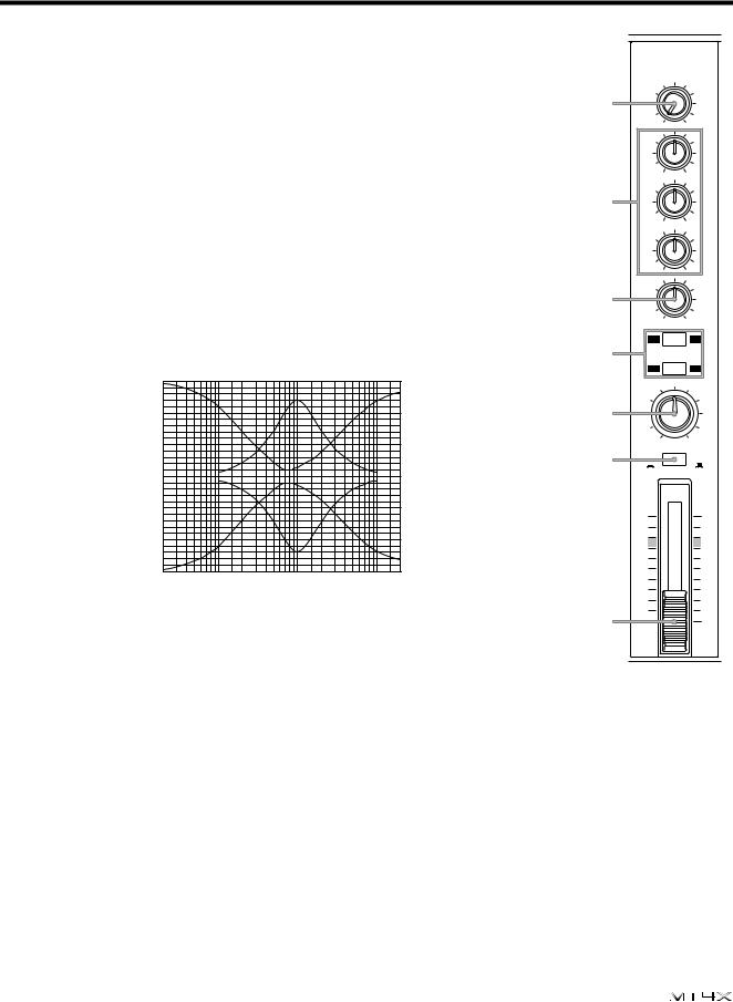
1 GAIN control
This rotary control adjusts the level of the signal from a microphone or instrument plugged into the MIC/LINE INPUT connector (H).
2 Equalizer controls
These rotary controls are used to adjust the high, middle and low band frequency levels. To help you select the ÒßatÓ setting easily, each control has a centre-detent at the Ò0Ó position.
HIGH |
±12 dB at 12kHz - shelving |
MID |
±12 dB at 1kHz - peaking |
LOW |
±12 dB at 80Hz - shelving |
|
15 |
|
|
|
|
|
|
|
|
|
|
10 |
|
|
|
|
|
|
|
|
|
(dB) |
5 |
|
|
|
|
|
|
|
|
|
RESPONSE |
0 |
|
|
|
|
|
|
|
|
|
|
|
|
|
|
|
|
|
|
|
|
|
–5 |
|
|
|
|
|
|
|
|
|
|
–10 |
|
|
|
|
|
|
|
|
|
|
–1520 |
50 |
100 |
200 |
500 |
1k |
2k |
5k |
10k |
20k |
FREQUENCY (Hz)
3 AUX controls
1
2
3
4
5
6
7
1
MIC/LINE
GAIN
LINE 0 MIC
HIGH
-12 |
0 |
+12 |
MID |
|
|
|
|
|
-12 |
0 |
+12 |
LOW |
|
|
|
|
|
-12 |
0 |
+12 |
AUX |
|
|
|
|
|
AUX 1 |
|
AUX 2 |
1 |
|
2 |
ASSIGN |
||
3 |
|
4 |
PAN |
C |
|
|
|
|
L |
|
R |
ODD |
|
EVEN |
TAPE |
|
MIC/ |
|
|
LINE |
10
9
8
7
6
5
4
3
2
1
0
This rotary control is used to send the channel signal after the fader (7) to the auxiliary send buses. Rotated fully counter-clockwise sends the signal to the AUX 1 bus, fully clockwise to the AUX 2 bus. In the centre-detent Ò0Ó position, no signal is sent to either bus.
4 ASSIGN keys
These keys are used to select the group bus.
1-ASSIGN-2
3-ASSIGN-4
|
|
|
|
|
1 |
|
|
|
2 |
|
|
|
|
|
|
|
|
|
|
3 |
|
|
|
4 |
|
|
|
|
|
selects the Þrst track group - groups 1 and 2.
selects the second track group - groups 3 and 4.
Use the PAN control (5) to select the individual track groups.
5 PAN control
This rotary control sets the stereo pan position of the channel signal. It is also used to select the individual track groups for recording.
UserÕs Guide
Downloaded from: http://www.usersmanualguide.com/
7 |
Controls and Connections |
ODD/L: Rotated fully counter-clockwise sends the signal to the odd (1 or 3) numbered track of the selected track group (ASSIGN keys 4) and to the left channel of the STEREO bus.
EVEN/R: Rotated fully clockwise sends the signal to the even (2 or 4) numbered track of the selected track group (ASSIGN keys) and to the right channel of the STEREO bus.
6 Input select (TAPE - MIC/LINE) key
This key selects the input source for the channel. Pressed in (  ), it selects the tape track corresponding to the channel module (for example, the channel 1 key selects track 1). In the out position (
  ), the source is the MIC/LINE INPUT connector (H).
7 Channel fader
This linear control is used to set the channel level. For optimal performance and signal balance, the fader should be positioned between 7 and 8.
Master Module
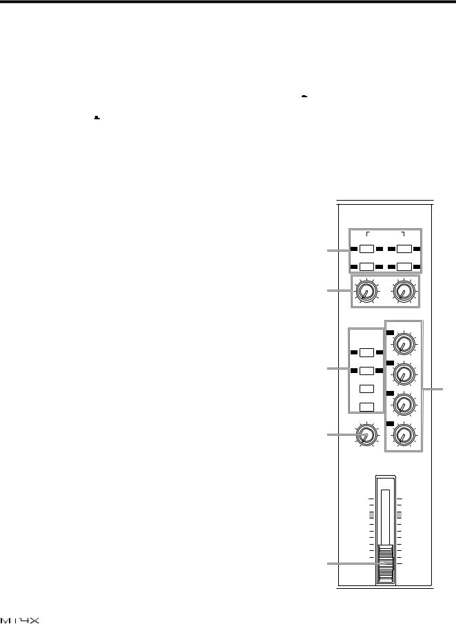
8 AUX RETURN - ASSIGN keys
These keys assign the signal from the AUX RETURN connectors |
|
(I) to the selected group bus. |
8 |
|
|
9 Auxiliary return LEVEL controls |
|
These rotary controls adjust the level of the auxiliary return |
9 |
signal. |
0 MONITOR SELECT keys
These keys are used to select the group buses, the stereo bus, |
|
and the cue bus signals. The signals are routed to the |
|
MONITOR OUT (F) connectors on the rear panel and the |
|
stereo PHONES (D) connector on the front of the MT4X. |
0 |
|
|
GROUP: These keys select groups 1 and 3 and groups 2 and 4 |
|
respectively. If you select both keys, groups 1 and 3 will be sent |
|
to the left channel and groups 2 and 4 will be sent to the right |
|
channel. |
|
STEREO: This key selects the stereo bus signal. |
B |
|
|
CUE: This key selects the cue bus signals. These are the playback |
|
signals direct from the cassette tracks. When you are recording, |
|
the record signal is monitored. |
|
MASTER
|
AUX RETURN |
|
|
||
|
1 |
|
|
2 |
|
1 |
2 |
1 |
|
2 |
|
ASSIGN |
|
ASSIGN |
|
||
3 |
4 |
3 |
|
4 |
|
|
LEVEL |
|
|
|
|
0 |
10 |
|
0 |
10 |
|
|
|
CUE LEVEL |
|
||
MONITOR |
1 |
|
|
|
|
SELECT |
|
|
|
|
|
1 |
3 |
|
0 |
10 |
|
GROUP |
|
|
|||
2 |
|
|
|
||
|
|
|
|
|
|
2 |
4 |
|
|
|
|
STEREO |
|
0 |
10 |
A |
|
|
|
3 |
|||
|
CUE |
|
|
|
|
MONITOR/PHONES |
0 |
10 |
|
||
|
|
4 |
|
|
|
MIN |
MAX |
|
0 |
10 |
|
A CUE LEVEL controls
These rotary controls adjust the level of the signal from each track before it is sent to the cue bus.
B MONITOR/PHONES level control
This rotary control adjusts the volume level of the stereo
PHONES (D) connector and the MONITOR OUT (F) C connectors.
10 |
10 |
9 |
9 |
8 |
8 |
7 |
7 |
6 |
6 |
5 |
5 |
4 |
4 |
3 |
3 |
2 |
2 |
1 |
1 |
0 |
0 |
UserÕs Guide
Downloaded from: http://www.usersmanualguide.com/
Controls and Connections |
8 |
C Master fader
This linear control is used to set the level of the master stereo bus. For optimal performance and signal balance, the fader should be positioned between 7 and 8.
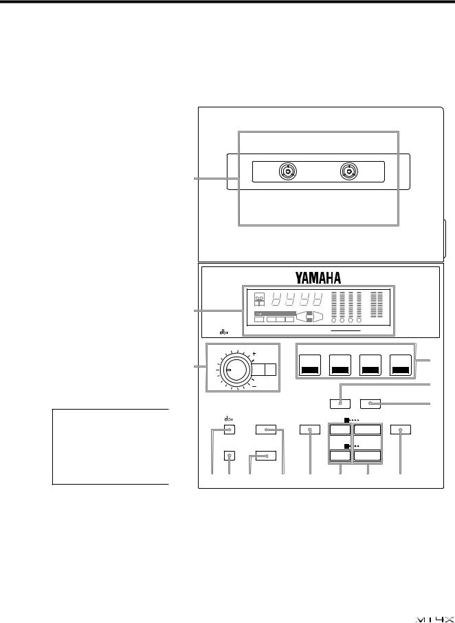
Recorder Controls
DCassette tape compartment
EMulti-function display
This FLD (Fluorescent Light Display) shows the operating modes and signal levels of the MT4X. See "Multi-function Display" on page 10.
F TAPE SPEED CONTROL
These controls consist of a rotary PITCH control and a tape speed (4.8/9.5) select key.
The PITCH control can adjust the tape speed by approximately ±10%.
The tape speed (4.8/9.5) select key is used to switch the tape speed between 9.5 cm/sec and 4.8 cm/sec. 9.5 cm/sec will be selected automatically when the power is turned on.
Note: The tape speed cannot be changed while the tape transport is in motion. Press the STOP key (W), then press the tape speed select key.
G REC SELECT keys
D
|
TAPE |
|
|
+9 |
|
|
|
|
+9 |
|
|
|
|
|
6 |
|
|
|
|
6 |
|
||
|
|
|
|
|
|
|
|
|
|
||
|
|
|
|
|
3 |
|
|
|
|
3 |
|
|
9.5 |
4.8 |
|
|
0 |
|
|
|
|
0 |
|
E |
|
|
|
|
3 |
|
|
|
|
3 |
|
|
|
|
|
6 |
|
|
|
|
6 |
|
|
|
AUTO PUNCH |
|
1 |
10 |
|
|
|
|
10 |
|
|
|
MEMO |
REPEAT |
-20 |
|
|
|
|
-20 |
|
||
|
SYNC START IN OUT |
|
2 |
REC |
1 |
2 |
3 |
4 |
L |
R |
|
|
NOISE REDUCTION SYSTEM |
|
|
|
1 |
2 |
3 |
4 |
STEREO |
||
|
|
|
|
|
TRACK |
|
|
|
|||
|
TAPE SPEED CONTROL |
|
|
|
|
REC SELECT |
|
||||
|
PITCH |
|
|
|
|
|
|
|
|
|
G |
F |
|
4.8 / 9.5 |
|
|
|
|
|
|
|
|
|
|
|
|
|
|
|
|
|
|
|
||
O |
|
|
1 |
|
|
2 |
|
|
3 |
4 |
|
|
|
|
|
|
|
|
|
|
|
RETURN |
H |
|
|
|
|
|
|
REPEAT |
|
|
TO ZERO |
|
|
|
|
|
|
|
|
|
|
|
|
|
I |
|
|
AUTO |
CHECK |
|
MEMO 1 |
|
LOCATE |
COUNTER |
|||
|
PUNCH I/O |
|
|
RESET |
|||||||
|
SYNC |
CLEAR |
|
|
|
MEMO 2 |
|
LOCATE |
|
||
|
J K L |
M |
N |
|
O |
|
|
P |
Q |
||
These keys are used to arm the tracks for recording. When you press a REC SELECT key, the record select indicator (C) for the corresponding track ßashes on the multi-function display (E).
H REPEAT key
This key is used to start and cancel the repeat function. When the repeat function is active, the MT4X will repeatedly playback a selection between two memory points set with the MEMO keys (O). See "Repeat Function" on page 42.
UserÕs Guide
Downloaded from: http://www.usersmanualguide.com/
9 |
Controls and Connections |
When the automatic punch-in/out function is active, the REPEAT key causes the MT4X to immediately start the rehearsal mode. See "Using the automatic punch-in/out function" on page 21.
Note: The repeat interval must be more than three counts on the tape counter (Y).
I RETURN TO ZERO key
This key rewinds the tape to the point where the tape counter (Y) reads Ò0000Ó. The tape counter ßashes while the tape rewinds.
J dbx key
This key is used to turn the dbxÔ noise reduction system on and off. By default, the dbxª system is turned on when the MT4X is Þrst powered on.
The dbxª system has no effect on track 4 when the SYNC key (K) is on. See "FSK recording" on page 35.
K SYNC key
This key defeats the dbxª noise reduction system on track 4. This allows you to record FSK signals onto the track. See "FSK recording" on page 35.
L CLEAR key
This key clears the stored memory points. When automatic punch-in/out is active (the
AUTO PUNCH indicator ^is illuminated), this key clears the current setting (but does not clear the memory points).
M AUTO PUNCH I/O key
This key is used to start and cancel the automatic punch-in/out function. See "Using the automatic punch-in/out function" on page 21.
N CHECK key
This key is used to verify the memory points. Press and hold this key and the press one of the MEMO keys (O). The corresponding MEMO indicator (A) will ßash and the stored value will be shown on the tape counter (Y).
O MEMO (1, 2) keys
These keys store the current tape counter (Y) value as memory points. When you press one of these keys, the corresponding MEMO indicator (A) will light and the point stored.
You can clear the memory points by pressing the CLEAR key (L), removing the cassette tape, or turning off the power.
P LOCATE (1, 2) keys
These keys locate to the stored memory points. When you press one of these keys, the MT4X will fast forward or rewind to the corresponding memory point.
Note: The locate interval must be more than three counts on the tape counter (Y).
Q COUNTER RESET key
This key resets the tape counter (Y) to Ò0000Ó.
UserÕs Guide
Downloaded from: http://www.usersmanualguide.com/
Controls and Connections |
10 |
Transport Controls
R REHE key and indicator
This key is used to perform a recording rehearsal. While the LED indicator over the key is illuminated, you can simulate a recording session. This allows you to check recording levels or practice punch-in/out without actually recording.
REHE |
REC/PAUSE |
PLAY |
REW |
FF |
STOP |
R S T U V W
S REC/PAUSE key and indicator
This key is used to record. Before you can actually record, you must arm the tracks with the
REC SELECT keys (G). Press this key to place the MT4X in record standby mode. Once you press the PLAY key (T), recording will begin.
Press the key again to pause the recording.
T
U
V
W
PLAY key and indicator
REW key
This key is used to rewind the cassette tape.
FF key
This key is used to fast forward the cassette tape.
STOP key
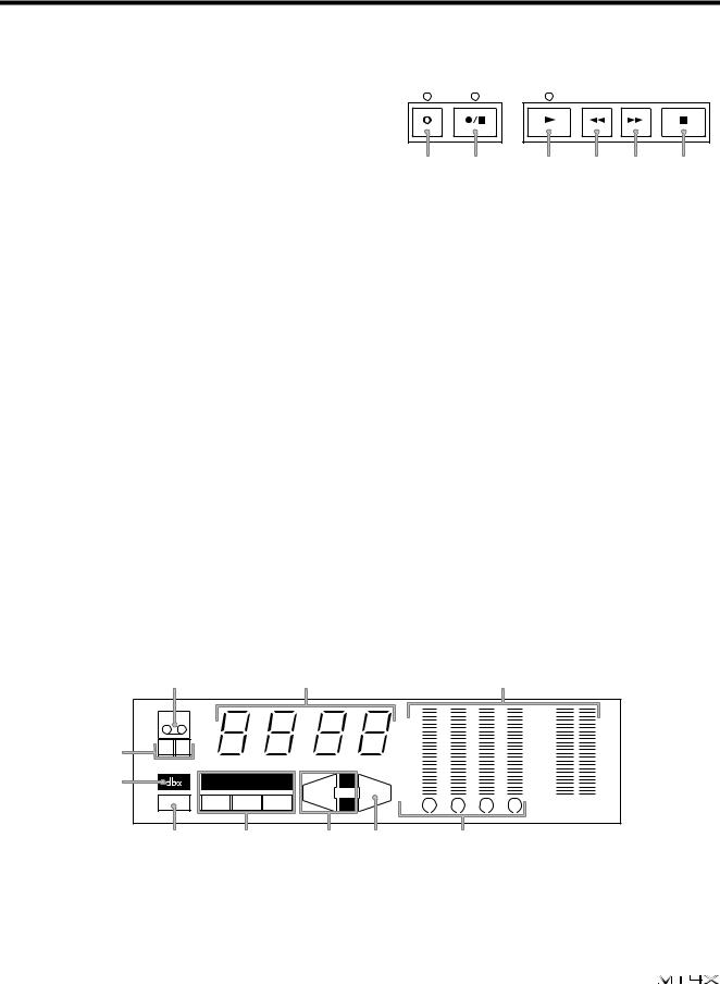
Multi-function Display
This section details the indicators of the FLD (Fluorescent Light Display) multi-function display
(E). |
|
|
|
|
|
|
|
|
|
|
|
|
X |
|
|
Y |
|
|
|
|
Z |
|
|
|
TAPE |
|
|
|
|
+9 |
|
|
|
+9 |
|
|
|
|
|
|
6 |
|
|
|
6 |
|
|
|
|
|
|
|
|
|
|
|
|
||
|
|
|
|
|
|
3 |
|
|
|
3 |
|
[ |
9.5 4.8 |
|
|
|
|
0 |
|
|
|
0 |
|
|
|
|
|
3 |
|
|
|
3 |
|
||
\ |
|
|
|
|
|
6 |
|
|
|
6 |
|
|
AUTO PUNCH |
1 |
|
10 |
|
|
|
10 |
|
||
|
MEMO |
REPEAT |
-20 |
|
|
|
-20 |
|
|||
|
|
|
|
|
|
|
|
||||
|
SYNC |
START IN |
OUT |
2 |
|
REC 1 |
2 |
3 |
4 |
L |
R |
|
] |
^ |
|
A |
B |
|
C |
|
|
|
|
X TAPE indicator
This indicator illuminates when a cassette tape is inserted in the cassette tape compartment. If you press any of the transport keys before you have inserted a tape, the indicator will ßash.
UserÕs Guide
Downloaded from: http://www.usersmanualguide.com/

11 Controls and Connections
Y
Z
Tape counter
This indicator displays tape position.
Level meters
These indicators display the signal level within a range of -20 dB to +9 dB. The individual tracks and the stereo bus are displayed.
¥When dbxª is off, the normal signal limit is approximately 0 dB.
¥When dbxª is on, the normal signal limit is approximately +6 dB.
Note: The meters can be switched to peak hold. To switch peak hold on or off, press the COUNTER RESET key (Q) while holding down the STOP key (W).
[ Tape speed indicator
These indicators show the current tape speed selection, either 9.5 cm/sec or 4.8 cm/sec. When the MT4X is Þrst powered on, it defaults to 9.5 cm/sec.
\
]
^
dbx indicator
This indicator illuminates when the dbxª noise reduction system is turned on.
SYNC indicator
This indicator illuminates when SYNC key (K) has been switched on.
AUTO PUNCH indicators
These indicators show the status of the automatic punch-in/out function. See "Using the automatic punch-in/out function" on page 21.
A MEMO indicators
These indicators illuminate when their respective memory points have been set.
B REPEAT indicator
This indicator illuminates while the repeat function is active.
C REC SELECT - TRACK indicators
These indicators ßash when you arm the corresponding track by pressing one of the REC SELECT keys (G). The armed indicators switch from ßashing to illuminated when you press the REC/ PAUSE key (S).
Front Panel Connections
D PHONES connector
This 1/4Ó phone connector is used for a pair of stereo headphones (8 Ω to 40 Ω).
E PUNCH I/O footswitch connector
This connector is used to plug in an optional footswitch (FC5) for punch-in/out recording. See "Using the optional footswitch" on page 28.
PHONES |
PUNCH I/O |
||||
|
|
|
|
|
|
|
|
|
|
|
|
|
|
|
|
|
|
D E
UserÕs Guide
Downloaded from: http://www.usersmanualguide.com/
Controls and Connections |
12 |
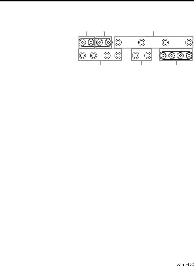
Rear Panel Connections
FMONITOR OUT connections
¥Output impedance: 1 kΩ
¥Nominal output level:
-10 dB (at 10 kΩ load)
These RCA/Phono connectors are used to plug in a monitor ampliÞer or powered loudspeakers. The same signal which is output from the PHONES connector (D) is also output from these connectors.
|
F |
G |
|
|
|
|
H |
|
|
|
MONITOR OUT |
STEREO OUT |
|
|
MIC/LINE INPUT |
|
|
|
|||
R |
L |
R |
L |
4 |
|
3 |
2 |
|
|
1 |
|
AUX RETURN |
|
|
|
AUX SEND |
|
TAPE OUT |
|
||
|
2 |
|
|
1 |
|
|
|
|
|
|
R |
L/MONO |
R |
|
L/MONO |
2 |
1 |
SYNC/4 |
3 |
2 |
1 |
|
|
|
|
|
||||||
|
|
I |
|
|
|
J |
|
|
K |
|
GSTEREO OUT connections
¥Output impedance: 1 kΩ
¥Nominal output level: -10 dB (at 10 kΩ load)
These RCA/Phono connectors are used to output the Þnal stereo mixdown to the master recorder Ñ typically, a stereo tape deck.
HMIC/LINE INPUT connections
¥Input impedance: 10 kΩ
¥Nominal input level: -10 dB to -50 dB
These 1/4Ó phone connectors are used to input microphones, electronic instruments, and line-level sources.
IAUX RETURN (1, 2) connections
¥Input impedance: 10 kΩ
¥Nominal input level: -10 dB (AUX RETURN - LEVEL control nominal)
These 1/4Ó phone connectors are used to input the signals from external effects devices and other signal processors. If the external device is monaural, plug it into one of the L/MONO connectors.
JAUX SEND (1, 2) connections
¥Output impedance: 1 kΩ
¥Nominal output level: -10 dB (at 10 kΩ load)
These 1/4Ó phone connectors are used to output signals to external effects devices and other signal processors.
KTAPE OUT (1 to 4/SYNC) connections
¥Output impedance: 1 kΩ
¥Nominal output level: -10 dB (at 10 kΩ load)
These RCA/Phono connectors are used to output the individual tracks directly from the recorder section of the MT4X.
UserÕs Guide
Downloaded from: http://www.usersmanualguide.com/
13 Controls and Connections
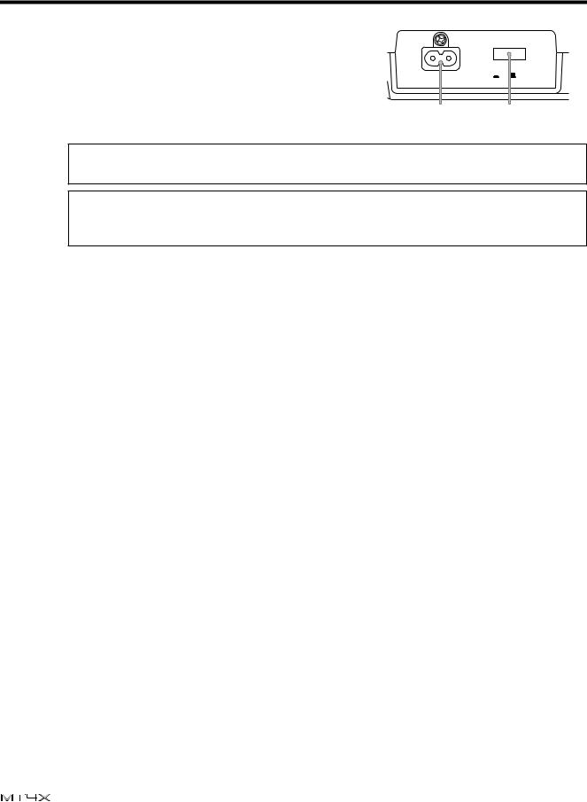
Power Connections
L AC IN inlet |
|
POWER |
Connect the supplied power cord here. |
IN |
ON OFF |
|
|
|
M POWER switch |
L |
M |
This switch turns the power on and off.
Note: Always make sure the Master fader (C) is set to “0” and the MONITOR/PHONES level control is set to “MIN” when turning the MT4X on or off.
CAUTION (FOR CANADIAN MODEL)
TO PREVENT ELECTRIC SHOCK, MATCH WIDE BLADE OF PLUG TO WIDE SLOT, FULLY INSERT.
UserÕs Guide
Downloaded from: http://www.usersmanualguide.com/

http://www from: Downloaded |
Guide UserÕs |
com/.usersmanualguide. |
|
|
|
|
|
|
|
|
|
MIDI |
|
|
OUT |
MIDI OUT |
MIDI IN |
MIDI IN |
Sequencer
Rhythm
Programmer
MIDI IN
Synthesizer
Multi-effect Signal Processor |
|
|
|
|
|
|
|
||||
Delay Processor |
|
|
|
|
|
|
STUDIO |
STUDIO |
|||
|
|
|
|
|
|
|
|
|
|
NS-10M |
NS-10M |
FSK Signal |
|
|
|
|
|
|
|
|
|
|
|
MIDI |
|
|
|
|
|
|
|
|
|
|
|
OUT |
|
|
|
|
|
|
|
|
|
|
|
1 |
2 |
3 |
SYNC/4 |
1 |
2 |
L/MONO |
|
R |
L/MONO |
R |
|
|
|
|
|
|
|
||||||
|
|
|
|
|
|
1 |
|
|
|
2 |
|
|
TAPEOUT |
|
|
|
AUXSEND |
|
|
AUXRETURN |
|
|
|
1 |
|
|
2 |
|
3 |
4 |
L |
R |
L |
R |
|
MIDI Converter |
|
|
MIC/LINEINPUT |
|
|
STEREOOUT |
MONITOROUT |
Amplifier |
|||
Master Recorder
System Example 2
Bassguitar
Bass Effect Processor
Microphone
FC5 Footswitch
Compressor
Headphones
System Example
14

15 Recording Functions
3Recording Functions
The basic functions of multitrack recording are as follows:
Monitoring
Initial recording Overdub recording
Punch-in/out recording Ping-pong recording Mixdown
Monitoring the recording or playback to listen for mistakes or unwanted distortion.
Recording the Þrst instrument or part.
Recording additional instruments or parts while monitoring the previously recorded tracks.
Correct mistakes or add short segments to an existing track.
Bounce several existing tracks onto another track.
Mix the results of your multitrack recording onto a stereo master tape.
Monitoring
The MT4X offers you a great deal of ßexibility in monitoring the status of your recordings. You can monitor the individual channel groups, the stereo bus, the cue bus, or any combination.
You control monitoring with the MONITOR SELECT keys 0:
GROUP The GROUP keys allow you to monitor the group bus signals. If you only press one key, you will hear monaural output. If you press both keys, you will hear groups 1 and 3 in the left channel and groups 2 and 4 in the right channel.
MONITOR
SELECT
1 |
3 |
|
The signals on the group buses go directly to the recorder. |
STEREO |
The STEREO key allows you to monitor the stereo bus signal. You can monitor |
|
the signals from the four input channels as well as the AUX RETURN signal. |
|
Some of these signals may not have been assigned to the group bus, allowing |
|
you to listen to signals that will not be recorded. |
CUE |
The CUE key allows you to monitor the playback signals directly from the |
|
cassette tracks. You can set the volume for each track with the CUE LEVEL |
|
controls. The cue bus is monaural. |
|
When you are recording, the record signal is monitored. |
GROUP
2 |
4 |
STEREO
CUE
MONITOR/PHONES
MIN MAX
Of these three monitor sources, you will probably Þnd the cue bus is the most useful. This bus allows you to monitor the previously recorded tracks as well as new material independently of the mixer section. It is sometimes very important to be able to listen directly to the tracks, for example, to compare different mixer settings to the original signal.
You adjust the overall monitoring level with the MONITOR/PHONES control.
UserÕs Guide
Downloaded from: http://www.usersmanualguide.com/
Recording Functions |
16 |
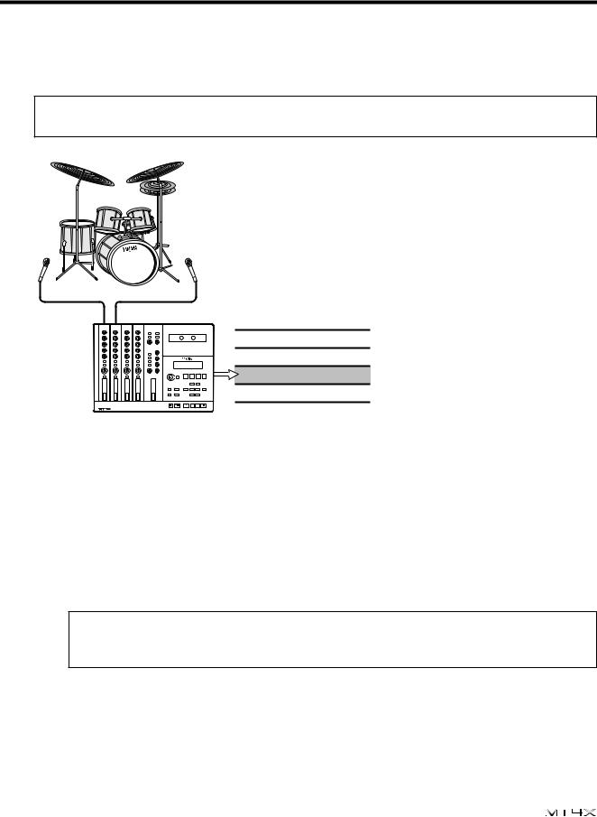
Initial recording
The Þrst step in multitrack recording is to record the initial tracks. Usually, these are your rhythm tracks: bassguitar, rhythm guitar, and drums.
Note: Before you record anything, you must connect the MT4X to both an input source and a monitoring system. See "Example System" on page 14.
|
|
a |
|
|
b n |
|
|
a |
d |
|
|
|
o |
||
el |
p |
n |
|
|
|
eop |
|
Track 1
Track 2
Track 3
Track to be recorded
Track 4
Preparations for recording
1)Insert a cassette tape into the cassette tape compartment (D).
2)Connect the input source to the corresponding MIC/LINE INPUT connector for each channel.
3)Set the input select key (6) to the MIC/LINE position.
4)Rotate the GAIN control (1) to adjust the initial level of the input signal.
If you have plugged a microphone into the corresponding connector, rotate the control fully clockwise to the MIC setting.
If you have plugged a synthesizer into the connector, or are running a bassguitar or guitar through a signal processor (line level output), rotate the control fully counter-clockwise to the LINE setting.
Note: This level setting is temporary — just to get a rough signal level based on the type of input you have connected. Be aware that you could easily be sending a signal that is overloading the gain amplifier and causing distortion. To set the final level, see steps 10 and 11.
UserÕs Guide
Downloaded from: http://www.usersmanualguide.com/
 Loading...