


 Loading...
MIXING CONSOLE
OWNER'S MANUAL
|
PHANTOM +48V |
OFF ON |
|
|
|
|
|
RTN |
SEND |
|
ST OUTPUT |
|
|
INPUT |
INPUT |
INPUT |
INPUT |
INPUT |
INPUT |
INPUT |
INPUT |
L(MONO) |
MONI |
|
|
|
|
MIC |
MIC |
MIC |
MIC |
MIC |
MIC |
MIC |
MIC |
|
1 |
|
|
|
|
|
|
|
|
|
|
||||||||
|
|
|
|
|
|
|
|
R |
EFFECT |
MONI |
|
|
|
|
|
|
|
|
|
|
|
|
|
2 |
L |
R |
|
|
|
|
|
|
|
|
|
|
|
|
|
||
|
|
|
|
|
|
|
|
|
|
|
1 |
|
|
LINE |
LINE |
LINE |
LINE |
LINE |
LINE |
LINE |
LINE |
9 L(MONO) |
11 L(MONO) |
|
3 |
|
|
|
|
|
|
|
|
|
|
|
|
|
2 |
|
C-R OUT |
INS |
INS |
INS |
INS |
|
|
|
|
10 R |
12 R |
|
|
|
|
I ⁄ O |
I ⁄ O |
I ⁄ O |
I ⁄ O |
INSERT I/O |
|
|
|
|
|
4 |
MIXING CONSOLE |
||
|
|
|
|
OUT IN |
|
|
|
|
|
|
GROUP |
|
PHONES |
|
1 |
2 |
3 |
4 |
5 |
6 |
7 |
8 INPUT |
|
|
|
||
|
INPUT |
|
OUTPUT |
|
|
||||||||
GAIN |
GAIN |
GAIN |
GAIN |
GAIN |
GAIN |
GAIN |
GAIN |
GAIN |
GAIN |
|
|
|
|
+10 |
-34 |
+10 |
-34 |
+10 |
-34 |
+10 |
-34 |
+10 |
-34 |
+10 |
-34 |
+10 |
-34 |
+10 |
-34 |
+10 |
-34 |
+10 |
-34 |
|
|
PHANTOM |
POWER |
0 |
10 |
-16 |
-60 |
-16 |
-60 |
-16 |
-60 |
-16 |
-60 |
-16 |
-60 |
-16 |
-60 |
-16 |
-60 |
-16 |
-60 |
|
L |
R |
|
||||||
PEAK |
|
PEAK |
|
PEAK |
|
PEAK |
|
PEAK |
|
PEAK |
|
PEAK |
|
PEAK |
|
PEAK |
|
PEAK |
L |
R |
|
C-R•PHONES |
|||
|
|
|
|
|
|
|
|
|
|
TAPE IN |
|
REC OUT |
|
|
|
||||||||||
HIGH |
|
HIGH |
|
HIGH |
|
HIGH |
|
HIGH |
|
HIGH |
|
HIGH |
|
HIGH |
|
HIGH |
|
HIGH |
|
|
|
|
|
METER |
|
|
|
|
|
|
|
|
|
|
|
|
|
|
|
|
|
|
|
|
|
|
|
RTN |
SEND |
|
|
|
|
|
|
|
|
|
|
|
|
|
|
|
|
|
|
|
|
|
|
|
|
C-R•PHONES |
|||
|
|
|
|
|
|
|
|
|
|
|
|
|
|
|
|
|
|
|
|
|
MONI |
|
|
|
|
-15 |
+15 |
-15 |
+15 |
-15 |
+15 |
-15 |
+15 |
-15 |
+15 |
-15 |
+15 |
-15 |
+15 |
-15 |
+15 |
-15 |
+15 |
-15 |
+15 |
|
|
|
|
MONI |
|
|
MONI 1 |
TAPE IN |
|
MID |
|
MID |
|
MID |
|
MID |
|
MID |
|
MID |
|
MID |
|
MID |
|
MID |
|
MID |
|
|
|
|
|
|
|
|
|
|
|
|
|
|
|
|
|
|
|
|
|
TAPE IN |
|
|
|
|
|
|
|
|
|||||||||||
|
|
|
|
|
|
|
|
|
|
|
|
|
|
|
|
|
|
|
|
|
|
0 |
10 |
0 |
|
10 |
0 |
10 |
ST |
-15 |
+15 |
-15 |
+15 |
-15 |
+15 |
-15 |
+15 |
-15 |
+15 |
-15 |
+15 |
-15 |
+15 |
-15 |
+15 |
-15 |
+15 |
-15 |
+15 |
ST |
|
ST |
|
ST |
|
|
EFFECT ⁄ MONI 2 |
EFFECT |
|
LOW |
|
LOW |
|
LOW |
|
LOW |
|
LOW |
|
LOW |
|
LOW |
|
LOW |
|
|
|
|
|
|
|
|
|
|
|
|
|
|
⁄ MONI |
|
|
|
|
|
|
|
|
LOW |
|
LOW |
|
|
|
|
|
|
|
|
|
|
|
||||||||
|
|
|
|
|
|
|
|
|
|
|
|
|
|
|
|
|
|
|
|
|
|
|
|
|
|
|
|
MONI 1 |
EFFECT |
|
|
|
|
|
|
|
|
|
|
|
|
|
|
|
|
|
|
|
|
0 |
10 |
0 |
10 |
0 |
|
10 |
0 |
/ MONI 2 |
|
|
|
|
|
|
|
|
|
|
|
|
|
|
|
|
|
|
|
|
|
|
10 |
|
|||||||
-15 |
+15 |
-15 |
+15 |
-15 |
+15 |
-15 |
+15 |
-15 |
+15 |
-15 |
+15 |
-15 |
+15 |
-15 |
+15 |
-15 |
+15 |
-15 |
+15 |
|
|
|
|
|
|
|
|
L |
R |
|
|
|
|
|
|
|
|
|
|
||||||||||||||||||||
MONI 1 |
|
MONI 1 |
|
MONI 1 |
|
MONI 1 |
|
MONI 1 |
|
MONI 1 |
|
MONI 1 |
|
MONI 1 |
|
MONI 1 |
|
MONI 1 |
|
|
|
|
|
|
|
|
|
PEAK |
|
|
|
|
|
|
|
|
|
|
|
|
|
|
|
|
|
|
|
|
|
DIGITAL |
|
|
|
|
|
|
|
|
+5 |
|
|
|
|
|
|
|
|
|
|
|
|
|
|
|
|
|
|
|
|
|
|
|
|
|
|
|
|
|
|
0 |
10 |
0 |
10 |
0 |
10 |
0 |
10 |
0 |
10 |
0 |
10 |
0 |
10 |
0 |
10 |
0 |
10 |
0 |
10 |
EFFECT |
VOCAL |
L HALL |
S HALL |
ON |
|
|
EFFECT |
+3 |
|
|
|
|
|
|
|
|
|
+1 |
|||||||||||||||||||||
EFFECT |
|
EFFECT |
|
EFFECT |
|
EFFECT |
|
EFFECT |
|
EFFECT |
|
EFFECT |
|
EFFECT |
|
EFFECT |
|
EFFECT |
|
|
|
|
|
|
|
|
|
MONI2 |
0 |
|
|
|
|
|
|
|
|
|
|
|
|
|
|
|
|
|
|
|
|
|
|
|
|
|
|
|
|
|
|
|
|
|
|
|
|
|
|
|
|
|
|
|
|
|
|
|
|
|
|
125 |
250 |
500 |
|
1k |
2k |
4k |
|
8k |
-1 |
|
|
|
|
|
|
|
|
|
|
|
|
|
|
|
|
|
|
|
|
|
|
|
|||||||
0 |
10 |
0 |
10 |
0 |
10 |
0 |
10 |
0 |
10 |
0 |
10 |
0 |
10 |
0 |
10 |
0 |
10 |
0 |
10 |
|
|
|
|
|
|
|
|
|
-3 |
|
|
|
|
|
|
|
|
|
|
||||||||||||||||||||
1 |
2 |
1 |
2 |
1 |
2 |
1 |
2 |
1 |
2 |
1 |
2 |
1 |
2 |
1 |
2 |
1 |
2 |
1 |
2 |
+12 |
+12 |
-5 |
|
6 |
6 |
-7 |
|||||||||||||||||||||
|
|
|
|
|
|
|
|
|
|
|
|
|
|
|
|
|
|
|
|
||||
|
|
|
|
|
|
|
|
|
|
|
|
|
|
|
|
|
|
|
|
0 |
0 |
-10 |
|
3 |
4 |
3 |
4 |
3 |
4 |
3 |
4 |
3 |
4 |
3 |
4 |
3 |
4 |
3 |
4 |
3 |
4 |
3 |
4 |
6 |
6 |
-15 |
|
|
|
|
|
|
|
|
|
|
|
|
|
|
|
|
|
|
|
|
|
-12 |
-12 |
-20 |
PAN |
PAN |
PAN |
PAN |
PAN |
PAN |
PAN |
PAN |
BAL |
BAL |
|
|
|
|
|
|
|
|
|
|
|
|
|
|
|
|
|
|
|
|
|
ST GRAPHIC EQUALIZER |
|
|
1 3 |
2 4 |
1 3 |
2 4 |
1 3 |
2 4 |
1 3 |
2 4 |
1 3 |
2 4 |
1 3 |
2 4 |
1 3 |
2 4 |
1 3 |
2 4 |
1 3 |
2 4 |
1 3 |
2 4 |
|
|
|
ST |
|
|
|
GROUP 3 4 |
||||||||||||||||||||
10 |
|
10 |
|
10 |
|
10 |
|
10 |
|
10 |
|
10 |
|
10 |
|
10 |
|
10 |
10 |
10 |
10 |
10 |
10 |
5 |
|
5 |
|
5 |
|
5 |
|
5 |
|
5 |
|
5 |
|
5 |
|
5 |
|
5 |
5 |
5 |
5 |
5 |
5 |
0 |
|
0 |
|
0 |
|
0 |
|
0 |
|
0 |
|
0 |
|
0 |
|
0 |
|
0 |
0 |
0 |
0 |
0 |
0 |
5 |
|
5 |
|
5 |
|
5 |
|
5 |
|
5 |
|
5 |
|
5 |
|
5 |
|
5 |
5 |
5 |
5 |
5 |
5 |
10 |
|
10 |
|
10 |
|
10 |
|
10 |
|
10 |
|
10 |
|
10 |
|
10 |
|
10 |
10 |
10 |
10 |
10 |
10 |
15 |
|
15 |
|
15 |
|
15 |
|
15 |
|
15 |
|
15 |
|
15 |
|
15 |
|
15 |
15 |
15 |
15 |
15 |
15 |
20 |
|
20 |
|
20 |
|
20 |
|
20 |
|
20 |
|
20 |
|
20 |
|
20 |
|
20 |
20 |
20 |
20 |
20 |
20 |
30 |
|
30 |
|
30 |
|
30 |
|
30 |
|
30 |
|
30 |
|
30 |
|
30 |
|
30 |
30 |
30 |
30 |
30 |
30 |
40 |
|
40 |
|
40 |
|
40 |
|
40 |
|
40 |
|
40 |
|
40 |
|
40 |
|
40 |
40 |
40 |
40 |
40 |
40 |
00 |
|
00 |
|
00 |
|
00 |
|
00 |
|
00 |
|
00 |
|
00 |
|
00 |
|
00 |
00 |
00 |
00 |
00 |
00 |
1 |
2 |
3 |
4 |
5 |
6 |
7 |
8 |
9 10 |
11 12 |
GROUP 1 |
GROUP 2 |
GROUP 3 |
GROUP 4 |
ST |
E
Downloaded from: http://www.usersmanualguide.com/

PRECAUTIONS
1.Avoid Excessive Heat, Humidity, Dust and Vibration
Keep the unit away from locations where it is likely to be exposed to high temperatures or humidity — such as near radiators, stoves, etc. Also avoid locations which are subject to excessive dust accumulation or vibration which could cause mechanical damage.
2.Ventilation
The unit has ventilation slots on the rear and bottom panels. Do not block these vents.
3.Avoid Physical Shocks
Strong physical shocks to the unit can cause damage. Handle it with care.
4.Do Not Open the Case or Attempt Repairs or Modifications Yourself
This product contains no user-serviceable parts. Refer all maintenance to qualified Yamaha service personnel. Opening the case and/or tampering with the internal circuitry voids the warranty.
FCC INFORMATION (U.S.A.)
1.IMPORTANT NOTICE: DO NOT MODIFY THIS UNIT! This product, when installed as indicated in the instructions contained in this manual, meets FCC requirements. Modifications not expressly approved by Yamaha may void your authority, granted by the FCC, to use the product.
2.IMPORTANT: When connecting this product to accessories and/or another product use only high quality shielded cables. Cable/s supplied with this product MUST be used. Follow all installation instructions. Failure to follow instructions could void your FCC authorization to use this product in the USA.
3.NOTE: This product has been tested and found to comply with the requirements listed in FCC Regulations, Part 15 for Class “B” digital devices. Compliance with these requirements provides a reasonable level of assurance that your use of this product in a residential environment will not result in harmful interference with other electronic devices. This equipment generates/uses radio frequencies and, if not installed and used according to the instructions found in the users manual, may cause interference harmful to the operation of other electronic devices. Compliance with FCC regulations does not guarantee that interference will not occur in all installations. If this product is found to be the source of interference, which can be determined by turning the unit “OFF” and “ON”, please try to eliminate the problem by using one of the following measures: Relocate either this product or the device that is being affected by the interference. Utilize power outlets that are on different branch (circuit breaker or fuse) circuits or install AC line filter/s. In the case of radio or TV interference, relocate/reorient the antenna. If the antenna lead-in is 300 ohm ribbon lead, change the lead-in to coaxial type cable. If these corrective measures do not produce satisfactory results, please contact the local retailer authorized to distribute this type of product. If you can not locate the appropriate retailer, please contact Yamaha Corporation of America, Electronic Service Division, 6600 Orangethorpe Ave, Buena Park, CA 90620
*This applies only to products distributed by YAMAHA CORPORATION OF AMERICA.
5.Always power off before making connections
Always turn the power OFF before connecting or disconnecting cables. This is important to prevent damage to the unit itself as well as other connected equipment.
6.Handle Cables Carefully
Always plug and unplug cables — including the AC power cord — by gripping the connector, not the cord.
7.Clean With a Soft Dry Cloth
Never use solvents such as benzine or thinner to clean the unit. Wipe clean with a soft, dry cloth.
8.Always Use the Correct Power Supply
Make sure that the power supply voltage specified on the rear panel matches your local AC mains supply. Also make sure that the AC mains supply can deliver more than enough current to handle all equipment used in your system.
IMPORTANT NOTICE FOR
THE UNITED KINGDOM
Connecting the Plug and Cord
WARNING: THIS APPARATUS MUST BE EARTHED
IMPORTANT: The wires in this mains lead are coloured in accordance with the following code:
GREEN-AND-YELLOW : EARTH
BLUE |
: NEUTRAL |
BROWN |
: LIVE |
As the colours of the wires in the mains lead of this apparatus may not correspond with the coloured markings identifying the terminals in your plug, proceed as follows:
The wire which is coloured GREEN and YELLOW must be connected to the terminal in the plug which is marked by the letter E or by the safety earth symbol or coloured GREEN and YELLOW.
The wire which is coloured BLUE must be connected to the terminal which is marked with the letter N or coloured BLACK.
The wire which is coloured BROWN must be connected to the terminal which is marked with the letter L or coloured RED.
*This applies only to products distributed by YAMAHA KEMBLE MUSIC (U.K.) LTD.
MX12/4—OWNER’S MANUAL
Downloaded from: http://www.usersmanualguide.com/

MX12/4 1
Thank you for purchasing the Yamaha MX12/4 mixing console. The MX12/4 is a 12 in/4 group out mixer that provides an ideal balance of operability, functionality, and simplicity.
In order to take full advantage of the MX12/4's functionality and to enjoy long and trouble-free use, please read this owner’s manual before use, and keep it for future reference.
Features
•The MX12/4 provides 12 input channels, and mixes them to stereo or to four group outputs.
•A C-R OUT jack is provided for convenient connection to a sub amp for monitoring. You can monitor the main stereo output, the TAPE IN input, and the effect/monitor signals.
•A digital effect unit is built-in, allowing you to create a polished mix without the need for additional equipment.
•Two SEND jacks are provided: the MONO 1 jack (pre fader) and the EFFECT/MONO 2 jack (post/ pre fader). These can be used as sends for external effects or a monitor system.
•Phantom power is provided, so that condenser microphones requiring an external power supply can be easily connected.
•INS I/O jacks are provided for input channels 1-4, allowing individual effects to be inserted into each channel.
•Input channels 1-8 provide both XLR type mic inputs and TRS phone line inputs. Channels 9-12 provide stereo line inputs. The MX12/4 accommodates a wide range of sources, from microphones to line level devices and stereo output synthesizers.
•TAPE IN jacks and REC OUT jacks make it easy to connect tape decks for playback and recording.
Contents |
|
Front panel ................................................. |
2 |
Channel control section .............................. |
2 |
Master control section................................. |
4 |
Connector section ....................................... |
6 |
Rear panel.................................................. |
8 |
Application Example................................... |
9 |
Specifications ........................................... |
10 |
General specifications............................... |
10 |
Input specifications ................................... |
11 |
Output specifications................................. |
11 |
Dimensions ............................................... |
12 |
Block and Level diagram........................... |
13 |
MX12/4—OWNER’S MANUAL
Downloaded from: http://www.usersmanualguide.com/
2 Front panel
Front panel
Channel control section
Channels 1~8
(monaural)
GAIN
+10 |
|
-34 |
|
-16 |
-60 |
||
PEAK |
|
|
|
HIGH |
|
|
|
-15 |
|
|
+15 |
MID |
|
|
|
-15 |
|
|
+15 |
LOW |
|
|
|
-15 |
|
|
+15 |
MONI |
|
|
|
0 |
|
|
10 |
EFFECT |
|
|
|
0 |
|
|
10 |
1 |
|
|
2 |
3 |
|
|
4 |
PAN |
|
|
|
1 |
3 |
2 |
4 |
10 |
|
|
|
5 |
|
|
|
0 |
|
|
|
5 |
|
|
|
10 |
|
|
|
15 |
|
|
|
20 |
|
|
|
30 |
|
|
|
40 |
|
|
|
00 |
|
|
|
1
Channels 9~12
(stereo)
GAIN
1
+10 -34
2 PEAK
PEAK
|
HIGH |
|
|
|
|
-15 |
|
+15 |
|
|
MID |
|
|
|
3 |
|
|
|
|
|
-15 |
|
+15 |
|
|
LOW |
|
|
|
|
-15 |
|
+15 |
|
|
MONI |
|
|
|
4 |
|
|
|
|
|
0 |
|
|
10 |
|
EFFECT |
|
|
|
5 |
|
|
|
|
|
0 |
|
|
10 |
|
1 |
|
|
2 |
6 |
|
|
|
|
|
3 |
|
|
4 |
|
BAL |
|
|
|
7 |
|
|
|
|
|
1 |
3 |
2 |
4 |
|
10 |
|
|
|
|
5 |
|
|
|
|
0 |
|
|
|
|
5 |
|
|
|
|
10 |
|
|
|
|
15 |
|
|
|
|
20 |
|
|
|
8 |
30 |
|
|
|
40 |
|
|
|
|
|
00 |
|
|
|
9 10
10
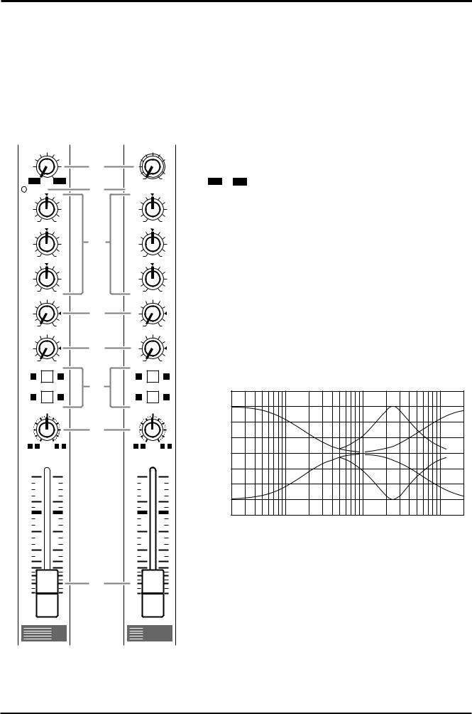
1 GAIN control
Use this knob to adjust the sensitivity according to the input signal level, so that the input level is appropriate.
For the best balance of S/N ratio and dynamic range, adjust this knob so that the peak indicator 2 lights occasionally.
–60 ~ –16 indicates the MIC input adjustment level, and –34~
+10 indicates the LINE input adjustment level.
2 PEAK indicator
This detects the peak level post EQ.
The indicator will light red 3dB before clipping, warning that clipping level is near.
3 Equalizer
This provides ± 15dB of control over the high, mid and low ranges at the following center frequencies.
HIGH : |
12kHz (shelving) |
MID : |
2.5kHz (peaking) |
LOW : |
80Hz (shelving) |
The frequency response will be flat when the knob is in the “▼” position.
|
+20 |
|
|
|
|
|
+15 |
|
|
|
|
|
+10 |
|
|
|
|
[dB] |
+5 |
|
|
|
|
Response |
0 |
|
|
|
|
–5 |
|
|
|
|
|
|
|
|
|
|
|
|
–10 |
|
|
|
|
|
–15 |
|
|
|
|
|
–20 |
100 |
1k |
10k |
20k |
|
20 |
Frequency [Hz]
4 MONI (monitor) control
This knob controls the level of the signal that is sent from each channel to the MONI bus.
Since this control is placed before the channel fader, it controls the level independently from the channel fader setting.
5 EFFECT control
This knob controls the level of the signal that is sent from each channel to the EFFECT bus.
Since this control is placed after the channel fader, the signal level will be affected by the channel fader setting.
MX12/4—OWNER’S MANUAL
Downloaded from: http://www.usersmanualguide.com/
Channel control section |
3 |
|
|
6Group select switches
These switches send the signal of each channel to GROUP buses 1~4.
When the 1 / 2 switches are on (pressed in), the signal will be sent to the GROUP buses 1/2. When the 3 / 4 switches are on (pressed in), the signal will be sent to the GROUP buses 3/4. When both switches are on, the signal will be sent to GROUP buses 1/2 and 3/4.
7PAN (panpot) control BAL (balance) control
The PAN knobs (channels 1~8) set the stereo position of the signal that is sent to the GROUP buses 1/2 or 3/4.
The BAL knobs (channels 9~12) set the balance between the left/right channels, and assign the signals received at inputs 9 L (MONO) and 11 L (MONO) to the GROUP buses 1/3, and the signals received at inputs 10 R and 12 R to the GROUP buses 2/4.
If signals are input monaurally to input 9 L (MONO) or 11 L (MONO), the same signal will be sent to groups 1~4.
8Channel fader
This controls the output level of the input channel signal, adjusting the volume balance between channels. The faders of unused channels should be lowered.
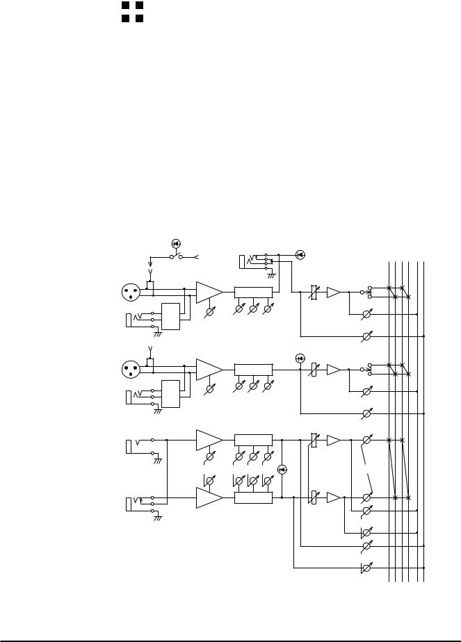
PHANTOM
PHANTOM
MASTER
MIC |
HA |
INPUT |
|
|
1-4 |
|
|
LINE |
PAD |
|
GAIN |
||
|
MIC |
HA |
|
INPUT |
|
|
5-8 |
|
|
LINE |
PAD |
|
GAIN |
||
|
||
L(MONO) |
HA |
|
|
||
INPUT |
GAIN |
|
9/10 |
|
|
11/12 |
|
|
|
HA |
|
R |
|
INS |
|
|
1 |
2 3 4 |
EFFECT MONI |
|
|
|
PEAK |
|
|
|
|
|
GROUP |
|
|
I/O |
|
|
|
|
|
|
EQ |
|
|
|
|
|
|
|
PAN |
|
|
LOW |
MID |
HIGH |
EFFECT |
|
|
|
|
|
MONI |
|
|
|
|
|
PEAK |
|
|
|
EQ |
|
|
|
|
|
|
|
PAN |
|
|
LOW |
MID |
HIGH |
EFFECT |
|
|
|
|
|
|
|
|
|
|
|
MONI |
|
|
|
EQ |
|
|
|
|
LOW MID HIGH |
BAL |
|
|
||
|
|
|
PEAK |
|
|
|
EQ |
|
|
|
|
|
|
|
EFFECT |
|
|
|
|
|
MONI |
|
|
|
|
|
MX12/4—OWNER’S MANUAL |
||
Downloaded from: http://www.usersmanualguide.com/
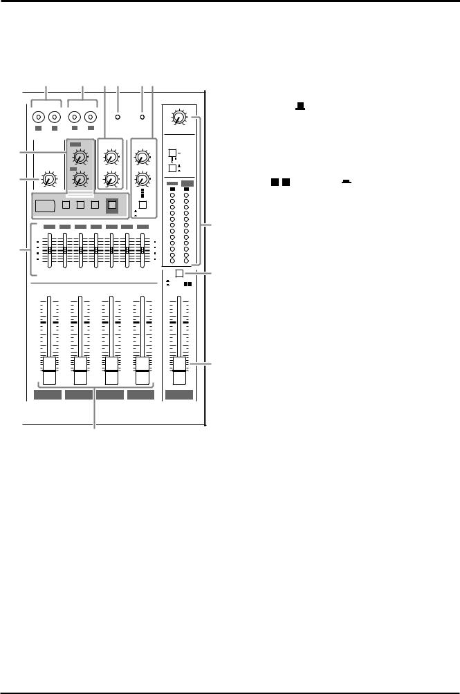
4 Front panel
Master control section
|
|
|
|
|
|
|
|
|
|
|
1 ST OUT output select switch |
|||
|
5 |
|
|
6 A7 |
8B |
|
|
This switch selects the signal which is output via the ST |
||||||
|
|
|
|
|
|
|
|
|
|
|
fader from the ST OUTPUT jacks. |
|||
|
|
|
|
|
|
|
|
|
|
|
ST position ( ) |
|||
|
|
|
|
|
|
PHANTOM |
POWER |
0 |
10 |
The ST OUTPUT jacks will output the ST bus signal |
||||
|
TAPE IN |
|
|
REC OUT |
|
|
|
|
(the post-fader signals of groups 1~4, the input signals |
|||||
|
L |
R |
L |
R |
|
|
|
|
C-R•PHONES |
|
|
|
|
|
|
|
|
MONI |
|
RTN |
|
SEND |
METER |
|
from the RTN jacks, the return signal from the internal |
||||
0 |
|
|
|
|
C-R•PHONES |
|||||||||
|
|
|
|
|
|
|
|
|
|
|||||
TAPE IN |
|
|
MONI |
|
MONI 1 |
|
|
digital effect, and the input signal from the TAPE IN |
||||||
|
|
|
|
|
|
|
|
TAPE IN |
||||||
|
ST |
|
ST |
10 |
ST |
10 |
EFFECT ⁄ MONI 2 |
|
EFFECT |
jacks). |
|
|
|
|
|
|
|
0 |
0 |
0 |
10 |
|
ST |
|
|
|
|
||
|
|
|
|
|
|
|
|
|
|
|
|
|
|
|
9 |
|
|
|
|
|
|
|
|
|
⁄ MONI |
GROUP |
|
|
position ( ) |
0 |
10 |
0 |
10 |
0 |
10 |
0 |
10 |
|
/ MONI 2 |
3 |
4 |
|||
|
|
|
|
|
|
|
|
MONI 1 |
EFFECT |
|
|
|||
|
|
|
|
|
|
|
|
|
L |
R |
The ST OUTPUT jacks will output the pre-fader sig- |
|||
|
|
|
|
|
|
|
|
|
PEAK |
|||||
|
EFFECT |
|
VOCAL L HALL S HALL |
ON |
|
EFFECT |
+5 |
|
nals of groups 3/4. |
|||||
|
DIGITAL |
|
|
|
|
|
|
|
+3 |
|
|
|
|
|
|
|
|
|
|
|
|
|
|
|
|
|
|
|
|
|
|
|
|
|
|
|
|
MONI2 |
+1 |
|
|
|
|
|
|
125 |
|
250 |
500 |
1k |
2k 4k |
|
-1 |
|
C When this position is selected, the input channel sig- |
||||
|
|
|
8k |
|
||||||||||
|
|
|
|
|
|
|
|
|
0 |
|
|
|
|
|
|
|
|
|
|
|
|
|
|
-5 |
|
nals will be sent directly to the ST bus without passing |
|||
|
|
|
|
|
|
|
|
|
-3 |
|
|
|
|
|
|
+12 |
|
|
|
|
|
|
+12 |
|
|
through the group buses 1~4. This setting lets you use |
|||
|
|
|
|
|
|
|
|
|
-10 |
|
||||
|
6 |
|
|
|
|
|
|
6 |
-7 |
|
|
|
|
|
4 |
|
|
|
|
|
|
|
|
|
|
|
|
||
0 |
|
|
|
|
|
|
0 |
-15 |
|
the MX12/4 as a simple 12 in-2 out mixer. |
||||
|
6 |
|
|
|
|
|
|
6 |
|
|||||
|
-12 |
|
|
|
|
|
|
-12 |
-20 |
|
|
|
|
|
|
|
|
ST GRAPHIC EQUALIZER |
|
|
ST |
|
1 2 ST master fader |
||||||
|
|
|
|
|
|
|
|
|
|
This fader adjusts the final combined level of all chan- |
||||
|
|
|
|
|
|
|
|
|
GROUP 3 4 |
|||||
|
|
|
|
|
|
|
|
|
|
|
|
|
||
|
10 |
|
10 |
|
10 |
|
10 |
|
10 |
|
nels, and sends the signal to the ST OUTPUT jacks. |
|||
|
5 |
|
5 |
|
5 |
|
5 |
|
5 |
|
The meters allow you to view the L and R output levels. |
|||
|
0 |
|
0 |
|
0 |
|
0 |
|
0 |
|
|
|
|
|
|
5 |
|
5 |
|
5 |
|
5 |
|
5 |
|
3 GROUP 1~4 faders |
|||
|
10 |
|
10 |
|
10 |
|
10 |
|
10 |
|
These faders adjust the signal levels of groups 1~4, and |
|||
|
15 |
|
15 |
|
15 |
|
15 |
|
15 |
|
send their signals to GROUP OUTPUT 1~4 jacks |
|||
|
30 |
|
30 |
|
30 |
|
30 |
|
30 |
|
||||
|
20 |
|
20 |
|
20 |
|
20 |
|
20 |
|
|
|
|
|
|
40 |
|
40 |
|
40 |
|
40 |
|
40 |
|
2 respectively and to the ST bus. |
|||
|
00 |
|
00 |
|
00 |
|
00 |
|
00 |
|
||||
|
|
|
|
|
Groups 1 and 3 are sent to ST L, and groups 2 and 4 are |
GROUP 1 |
GROUP 2 |
GROUP 3 |
GROUP 4 |
ST |
sent to ST R. |
4 Stereo graphic EQ
This is a stereo 7-band graphic equalizer that adjust the 3 tonal quality of the signal output to the ST OUTPUT
jacks.
A ± 12dB boost or cut is provided at each of the frequency bands 125, 250, 500, 1k, 2k, 4k, and 8kHz.
5TAPE IN jacks
These are line level input jacks to which an external DAT recorder or CD player etc. can be connected for monitoring. The signals which are input here are sent to the ST bus. The input levels are adjusted by the TAPE IN ST control (9). Depending on the setting of the C-R• PHONES select switch (D), the signal can also be monitored directly from the C-R OUT jack.
6REC OUT jacks
These jacks allow an external DAT recorder or cassette recorder to be connected, to record the same signal as the ST OUTPUT jacks.
The signals that are output from these jacks are not affected by the settings of the ST master fader or the graphic EQ. Make recording level adjustments on the recording device.
7PHANTOM indicator
This indicator will light when the PHANTOM switch (rear panel 2) is on.
8POWER indicator
This indicator will light when the MX12/4's power is on.
MX12/4—OWNER’S MANUAL
Downloaded from: http://www.usersmanualguide.com/
Loading...