


 Loading...
U
CRX-E500 RX-E400
CDC-E500
Receiver/CD Player
OWNER’S MANUAL
SAFETY INSTRUCTIONS
CAUTION |
RISK OF ELECTRIC SHOCK |
DO NOT OPEN |
CAUTION: TO REDUCE THE RISK OF |
ELECTRIC SHOCK, DO NOT REMOVE |
COVER (OR BACK). NO USER-SERVICEABLE |
PARTS INSIDE. REFER SERVICING TO |
QUALIFIED SERVICE PERSONNEL. |
•Explanation of Graphical Symbols
The lightning flash with arrowhead symbol, within an equilateral triangle, is intended to alert you to the presence of uninsulated “dangerous voltage” within the product’s enclosure that may be of sufficient magnitude to constitute a risk of electric shock to persons.
The exclamation point within an equilateral triangle is intended to alert you to the presence of important operating and maintenance (servicing) instructions in the literature accompanying the appliance.
WARNING
TO REDUCE THE RISK OF FIRE OR ELECTRIC SHOCK, DO NOT EXPOSE THIS UNIT TO RAIN OR MOISTURE.
1Read Instructions – All the safety and operating instructions should be read before the product is operated.
2Retain Instructions – The safety and operating instructions should be retained for future reference.
3Heed Warnings – All warnings on the product and in the operating instructions should be adhered to.
4Follow Instructions – All operating and use instructions should be followed.
5Cleaning – Unplug this product from the wall outlet before cleaning. Do not use liquid cleaners or aerosol cleaners. Use a damp cloth for cleaning.
6Attachments – Do not use attachments not recommended by the product manufacturer as they may cause hazards.
7Water and Moisture – Do not use this product near water – for example, near a bath tub, wash bowl, kitchen sink, or laundry tub; in a wet basement; or near a swimming pool; and the like.
8Accessories – Do not place this product on an unstable cart, stand, tripod, bracket, or table. The product may fall, causing serious injury to a child or adult, and serious damage to the product. Use only with a cart, stand, tripod, bracket, or table recommended by the manufacturer, or sold with the product. Any mounting of the product should follow the manufacturer’s instructions, and should use a mounting accessory recommended by the manufacturer.
9A product and cart combination should be moved with care. Quick stops, excessive
force, and uneven surfaces may cause the product and cart combination to overturn.
10Ventilation – Slots and openings in the cabinet are provided for ventilation and to ensure reliable operation of the product and to protect it from overheating, and these openings must not be blocked or covered. The openings should never be blocked by placing the product on a bed, sofa, rug, or other similar surface. This product should not be placed in a built-in installation such as a bookcase or rack unless proper ventilation is provided or the manufacturer’s instructions have been adhered to.
11Power Sources – This product should be operated only from the type of power source indicated on the marking label. If you are not sure of the type of power supply to your home, consult your product dealer or local power company. For products intended to operate from battery power, or other sources, refer to the operating instructions.
12Grounding or Polarization – This product may be equipped with a polarized alternating current line plug (a plug having one blade wider than the other). This plug will fit into the power outlet only one way. This is a safety feature. If you are unable to insert the plug fully into the outlet, try reversing the plug. If the plug should still fail to fit, contact your electrician to replace your obsolete outlet. Do not defeat the safety purpose of the polarized plug.
13Power-Cord Protection – Power-supply cords should be routed so that they are not likely to be walked on or pinched by items placed upon or against them, paying particular attention to cords at plugs, convenience receptacles, and the point where they exit from the product.
14Lightning – For added protection for this product during a lightning storm, or when it is left unattended and unused for long periods of time, unplug it from the wall outlet and disconnect the antenna or cable system. This will prevent damage to the product due to lightning and power-line surges.
15Power Lines – An outside antenna system should not be located in the vicinity of overhead power lines or other electric light or power circuits, or where it can fall into such power lines or circuits. When installing an outside antenna system, extreme care should be taken to keep from touching such power lines or circuits as contact with them might be fatal.
16Overloading – Do not overload wall outlets, extension cords, or integral convenience receptacles as this can result in a risk of fire or electric shock.
17Object and Liquid Entry – Never push objects of any kind into this product through openings as they may touch dangerous voltage points or short-out parts that could result in a fire or electric shock. Never spill liquid of any kind on the product.
18Servicing – Do not attempt to service this product yourself as opening or removing covers may expose you to dangerous voltage or other hazards. Refer all servicing to qualified service personnel.
19Damage Requiring Service – Unplug this product from the wall outlet and refer servicing to qualified service personnel under the following conditions:
a)When the power-supply cord or plug is damaged,
b)If liquid has been spilled, or objects have fallen into the product,
c)If the product has been exposed to rain or water,
I CAUTION

SAFETY INSTRUCTIONS
d)If the product does not operate normally by following the operating instructions. Adjust only those controls that are covered by the operating instructions as an improper adjustment of other controls may result in damage and will often require extensive work by a qualified technician to restore the product to its normal operation,
e)If the product has been dropped or damaged in any way, and
f)When the product exhibits a distinct change in performance - this indicates a need for service.
20Replacement Parts – When replacement parts are required, be sure the service technician has used replacement parts specified by the manufacturer or have the same characteristics as the original part. Unauthorized substitutions may result in fire, electric shock, or other hazards.
21Safety Check – Upon completion of any service or repairs to this product, ask the service technician to perform safety checks to determine that the product is in proper operating condition.
22Wall or Ceiling Mounting – The unit should be mounted to a wall or ceiling only as recommended by the manufacturer.
23Heat – The product should be situated away from heat sources such as radiators, heat registers, stoves, or other products (including amplifiers) that produce heat.
Note to CATV system installer:
This reminder is provided to call the CATV system installer’s attention to Article 820-40 of the NEC that provides guidelines for proper grounding and, in particular, specifies that the cable ground shall be connected to the grounding system of the building, as close to the point of cable entry as practical.
24Outdoor Antenna Grounding – If an outside antenna or cable system is connected to the product, be sure the antenna or cable system is grounded so as to provide some protection against voltage surges and built-up static charges. Article 810 of the National Electrical Code, ANSI/NFPA 70, provides information with regard to proper grounding of the mast and supporting structure, grounding of the lead-in wire to an antenna discharge unit, size of grounding conductors, location of antenna discharge unit, connection to grounding electrodes, and requirements for the grounding electrode.
EXAMPLE OF ANTENNA GROUNDING
MAST |
ANTENNA |
|
LEAD IN |
|
WIRE |
GROUND |
|
CLAMP |
|
|
ANTENNA |
|
DISCHARGE UNIT |
|
(NEC SECTION 810–20) |
ELECTRIC |
|
SERVICE |
|
EQUIPMENT |
GROUNDING CONDUCTORS |
|
|
|
(NEC SECTION 810–21) |
|
GROUND CLAMPS |
|
POWER SERVICE GROUNDING |
|
ELECTRODE SYSTEM |
|
(NEC ART 250. PART H) |
NEC – NATIONAL ELECTRICAL CODE |
|
FCC INFORMATION (for US customers)
1. IMPORTANT NOTICE : DO NOT MODIFY THIS |
Compliance with FCC regulations does not guarantee |
|
UNIT! |
that interference will not occur in all installations. If |
|
This product, when installed as indicated in the |
this product is found to be the source of interference, |
|
instructions contained in this manual, meets FCC |
which can be determined by turning the unit “OFF” and |
|
requirements. Modifications not expressly approved |
“ON”, please try to eliminate the problem by using one |
|
by Yamaha may void your authority, granted by the |
of the following measures: |
|
FCC, to use the product. |
Relocate either this product or the device that is being |
|
2. IMPORTANT : When connecting this product to |
affected by the interference. |
|
accessories and/or another product use only high |
Utilize power outlets that are on different branch (circuit |
|
quality shielded cables. Cable/s supplied with this |
breaker or fuse) circuits or install AC line filter/s. |
|
product MUST be used. Follow all installation |
In the case of radio or TV interference, relocate/reorient |
|
instructions. Failure to follow instructions could void |
||
the antenna. If the antenna lead-in is 300 ohm ribbon |
||
your FCC authorization to use this product in the USA. |
||
lead, change the lead-in to coaxial type cable. |
||
|
||
3. NOTE : This product has been tested and found to |
If these corrective measures do not produce satisfactory |
|
comply with the requirements listed in FCC |
||
results, please contact the local retailer authorized to |
||
Regulations, Part 15 for Class “B” digital devices. |
||
distribute this type of product. If you can not locate the |
||
Compliance with these requirements provides a |
||
appropriate retailer, please contact Yamaha Electronics |
||
reasonable level of assurance that your use of this |
||
Corp., U.S.A. 6660 Orangethorpe Ave, Buena Park, CA |
||
product in a residential environment will not result in |
||
90620. |
||
harmful interference with other electronic devices. |
||
The above statements apply ONLY to those products |
||
This equipment generates/uses radio frequencies and, |
||
distributed by Yamaha Corporation of America or its |
||
if not installed and used according to the instructions |
||
subsidiaries. |
||
found in the users manual, may cause interference |
||
|
||
harmful to the operation of other electronic devices. |
|
CAUTION II

CAUTION: READ THIS BEFORE OPERATING THIS UNIT
1To assure the finest performance, please read this manual carefully. Keep it in a safe place for future reference.
2Install this unit in a well ventilated, cool, dry, clean place away from direct sunlight, heat sources, vibration, dust, moisture or cold. In a cabinet, allow about 10 cm (4 in.) of free space all around RX-E400 for adequate ventilation.
3Locate this unit away from other electrical appliances, motors, or transformers to avoid humming sounds.
4Do not expose this unit to sudden temperature changes from cold to hot, nor locate this unit in an environment with high humidity (i.e., a room with a humidifier) to prevent condensation inside this unit, which may cause an electrical shock, fire, damage to this unit, and/or personal injury.
5Avoid installing this unit in a location where foreign objects may fall onto this unit or where this unit may be exposed to liquid dripping or splashing. On the top of this unit, do not place:
•Other components, as they may cause damage and/or discoloration on the surface of this unit.
•Burning objects (i.e., candles), as they may cause fire, damage to this unit, and/or personal injury.
•Containers with liquid in them, as they may fall, spilling the liquid and causing an electrical shock to the user and/or damage to this unit.
6Do not cover this unit with a newspaper, tablecloth, curtain, etc. in order not to obstruct heat radiation. If the temperature inside this unit rises, it may cause fire, damage to this unit, and/or personal injury.
7Do not plug in this unit to a wall outlet until all connections are complete.
8Do not operate this unit upside-down. It may overheat, possibly causing damage.
9Do not use excessive force on switches, knobs and/or cords.
10When disconnecting the power cord from the wall outlet, grasp the plug; do not pull the cord.
11Do not clean this unit with chemical solvents; this might damage the finish. Use a clean, dry cloth.
12Use only the voltage specified on this unit. Using this unit with a higher voltage than specified is dangerous and may cause fire, damage to this unit, and/or personal injury. YAMAHA will not be held responsible for any damage resulting from use of this unit with a voltage other than as specified.
13To prevent damage by lightning, disconnect the power cord from the wall outlet during an electrical storm.
14Do not attempt to modify or fix this unit. Contact qualified YAMAHA service personnel when any service is needed. The cabinet should never be opened for any reason.
15When not planning to use this unit for long periods of time (i.e., vacation), disconnect the AC power plug from the wall outlet.
16Be sure to read the “Troubleshooting” section on common operating errors before concluding that this unit is faulty.
17Before moving this unit, press STANDBY/ON to set the unit in standby mode, then disconnect the AC power plug from the wall outlet.
18VOLTAGE SELECTOR (General model only)
The VOLTAGE SELECTOR on the rear panel of this unit must be set for your local main voltage BEFORE plugging into the AC main supply. Voltages are 110/120/ 220/240 V AC, 50/60 Hz.
To reduce the risk of fire or electric shock, do not expose this appliance to rain or moisture.
The unit is not disconnected from the AC power source as long as it is connected to the wall outlet, even if this unit itself is turned off. This state is called the standby mode. In this state, this unit is designed to consume a very small quantity of power.
CAUTION FOR CARRYING THE UNIT
Before carrying the unit, first remove the disc from the unit, press STANDBY/ON to turn the unit off, then disconnect the AC power plug from the wall outlet.
FOR CANADIAN CUSTOMERS
To prevent electric shock, match wide blade of plug to wide slot and fully insert.
This Class B digital apparatus complies with Canadian ICES-003.
CAUTION
Use of controls or adjustments or performance of procedures other than those specified herein may result in hazardous radiation exposure.
Laser component in this product is capable of emitting radiation exceeding the limit for Class 1.
RX-E400 (U.S.A., Canada and General models) The nameplate is located on the bottom of the unit.
IMPORTANT
Please record the serial number of this unit in the space below.
MODEL:
Serial No.:
The serial number is located on the buttom of the unit. Retain this Owner’s Manual in a safe place for future reference.
We Want You Listening For A Lifetime
YAMAHA and the Electronic Industries Association’s Consumer Electronics Group want you to get the most out of your equipment by playing it at a safe level. One that lets the sound come through loud and clear without annoying blaring or distortion – and, most importantly, without affecting your sensitive hearing.
Since hearing damage from loud sounds is often undetectable until it is too late, YAMAHA and the Electronic Industries Association’s Consumer Electronics Group recommend you to avoid prolonged exposure from excessive volume levels.
III CAUTION

FEATURES
<RX-E400>
•Minimum RMS output power per
channel 40 W + 40 W
(6Ω, 20 Hz to 20 kHz, 0.1% THD)
•Full operation system remote control
•40-Station FM/AM preset tuning
•SUBWOOFER output terminal
<CDC-E500>
•3-Disc CD changer
•PLAYXCHANGE
Disc changing while playing
•S-bit DAC and 8fs digital filter
•Optical digital output
•Random, repeat, and program play
•CD TEXT display
•CD-RW compatible
The receiver (RX-E400) and CD player (CDC-E500) are the main units of the YAMAHA Piano Craft Series. You can upgrade the system by adding the cassette deck (KX-E300) and MD recorder (MDX-E300)*.
* MD recorder (MDX-E300) may not be available for some areas.
CONTENTS
SUPPLIED ACCESSORIES ....................... |
2 |
CD PREVENTIVE CARE .......................... |
2 |
GETTING STARTED |
|
Notes on the transportation pad ........................... |
3 |
Remote control .................................................... |
4 |
Connecting the speakers and antennas ................ |
5 |
Connecting the system ......................................... |
6 |
Setting the clock .................................................. |
7 |
Adjusting the brightness of the display ............... |
7 |
<RX-E400> |
|
NAMES OF BUTTONS AND CONTROLS |
|
Front panel ........................................................... |
8 |
Display ................................................................. |
8 |
Remote control .................................................... |
9 |
BASIC OPERATIONS |
|
Listening to a source .......................................... |
10 |
TUNING |
|
Listening to the radio ......................................... |
11 |
Presetting stations .............................................. |
12 |
USING THE BUILT-IN TIMER |
|
Before using the timer ....................................... |
13 |
Timer play and recording .................................. |
13 |
Sleep timer ......................................................... |
14 |
<CDC-E500>
NAMES OF BUTTONS AND CONTROLS
Front panel ......................................................... |
15 |
Display............................................................... |
15 |
Remote control .................................................. |
16 |
CD OPERATIONS |
|
Playing a disc ..................................................... |
17 |
Selecting the time display and CD TEXT ......... |
18 |
Random-sequence play ...................................... |
19 |
Repeat play ........................................................ |
19 |
Program play ..................................................... |
20 |
SYSTEM CONTROL |
|
Controlling other components ........................... |
21 |
Before recording ................................................ |
22 |
CD synchronized recording ............................... |
22 |
Dubbing setting ................................................. |
22 |
ADDITIONAL INFORMATION |
|
Troubleshooting ................................................. |
24 |
Specifications .................................................... |
26 |
1
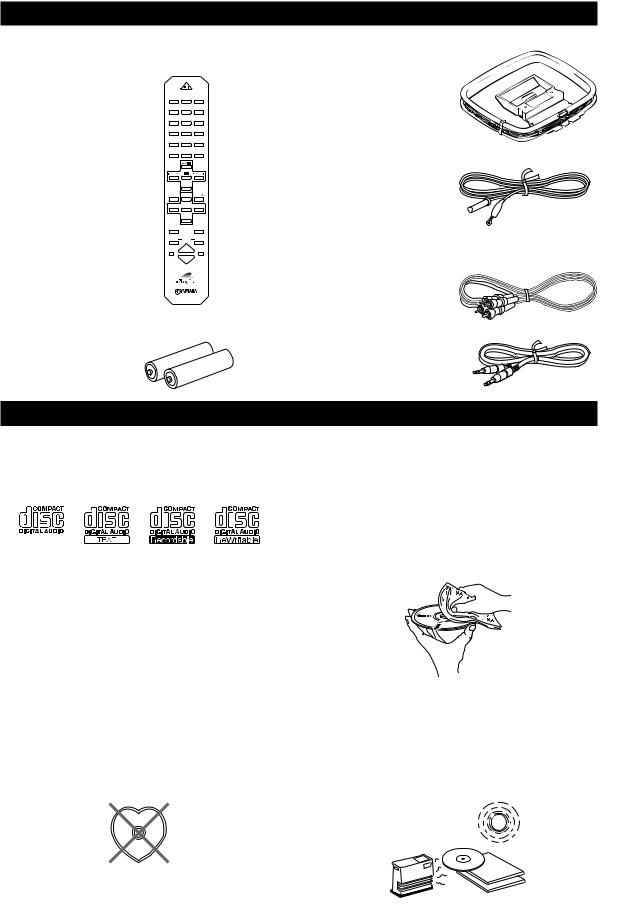
SUPPLIED ACCESSORIES
After unpacking, check that the following parts are contained.
<RX-E400> |
|
POWER |
|
• Remote control |
1 |
2 |
3 |
|
1 |
2 |
3 |
|
4 |
5 |
6 |
|
4 |
5 |
6 |
|
7 |
8 |
9 |
|
7 |
8 |
|
|
0 |
+10 |
+100 |
|
REP |
RANDOM |
PROG |
|
A |
B |
C |
|
MODE |
TEXT/TIME |
DISC SKIP |
|
D |
|
E |
|
|
TAPE |
|
|
|
DIRECTION |
|
|
PRESET |
TUNER |
PRESET |
|
MD |
CD |
TAPE |
|
|
AUX |
|
|
MD |
|
TAPE |
|
REC/PAUSE |
|
REC/PAUSE |
|
MODE |
DUBBING |
START |
|
SLEEP |
|
DISPLAY |
|
VOLUME |
||
• Batteries (AA, R6, UM-3)
• AM loop antenna
• Indoor FM antenna
<CDC-E500>
•Audio pin cable
•System control cable
CD PREVENTIVE CARE
•This compact disc player is designed for use with following types of disc only. Never attempt to load any other type of disc into the unit. The unit will also play 8-cm (3-inch) compact discs.
(Playback only)
•Be sure to use only CD-R and CD-RW discs made by reliable manufacturers.
•Some discs cannot be played depending on the disc characteristics or recording conditions (copyrightprotected in a particular way, etc.).
•Compact discs are not subjected to wear during play, but damage to the disc surface when the disc is being handled can adversely affect the disc’s play.
•Do not use cleaning discs or warped discs. All of these could damage the unit.
To prevent a malfunction of this unit
•Do not use any non standard shaped CD (heart, etc.) available on the market, because it may damage the unit.
•Do not use a CD with tape, seals, or paste on it, because damage to the unit may result.
•Do not use any disc that has had its surface printed by a commercially-available label printer.
•Compact discs are not affected by small particles of dust or fingerprints on their playing surface, but even so they should be kept clean. Wipe by using a clean, dry cloth. Do not wipe with a circular motion; wipe straight outward from the center.
•Do not try to clean the disc’s surface by using any type of disc cleaner, record spray, antistatic spray or liquid, or any other chemical-based liquid, because such substances might irreparably damage the disc’s surface.
•Do not expose discs to direct sunlight, high temperature or high humidity for a long period of time, because these might warp or otherwise damage the disc.
No!
2

GETTING STARTED
Notes on the
transportation pad
CDC-E500 is shipped with a transportation pad to prevent impact to the internal mechanism that could occur during transportation. Before turning CDC-E500 on, make sure to remove the pad.
Before using the unit
1 Take off the caution label.
Installing the transportation pad
Keep the pad and the caution label, and reattach it as described below whenever the unit is moved. Before attaching it, remove all discs from the disc tray.
1 Press DISC 1  , DISC 2
  or DISC 3
  to open the tray.
•When just one disc holder comes out, press DISC SKIP so that two holders come out.
2 Pass the strip of the pad through the hole to bind two disc holders together.
|
|
|
00 |
|
|
|
C–E5 |
|
|
|
ER CD |
|
ACT |
DISC |
PLAY |
UND |
COMP |
|
|
RAL SO |
|
|
|
NATU |
|
|
|
2 Draw the pad out.
NATURAL SOUND COMPACT DISC PLAYER CDC–E500
3 Fix the strip on the pad with the caution label.
4 Press STANDBY/ON on CDC-E500 to close the disc tray.
3

GETTING STARTED
Remote control
This remote control controls a whole system: not only RX-E400 but also CDC-E500. Moreover, a cassette deck (KX-E300) and MD recorder (MDX-E300) that level up your system can be operated by it. Operating buttons for each unit are explained on the pages below:
Receiver, RX-E400: |
p.8 |
CD player, CDC-E500: |
p.15 |
Cassette deck, KX-E300: |
p.21 |
MD recorder, MDX-E300: |
p.21 |
Battery installation
1
3

 2
2
1 Remove the battery compartment cover.
2 Insert batteries into the battery compartment.
3 Replace the battery compartment cover.
Battery replacement
If you find that the remote control must be used closer to the main unit than usual, the batteries are weak. Replace batteries with new ones.
Notes
•Use only AA, R6, UM-3 batteries for replacement.
•Be sure the polarities are correct. (See the illustration inside the battery compartment.)
•Remove the batteries if the remote control will not be used for an extended period of time.
•If batteries leak, dispose of them immediately. Avoid touching the leaked material or letting it come in contact with clothing, etc. Clean the battery compartment thoroughly before installing new batteries.
Remote control operation range
VOLUME
NATURAL SOUND STEREO RECEIVER RX–E400
STANDBY/ON
TIMER |
DISPLAY |
MEMORY |
AUTO/MAN'L PRESET/BAND |
PRESET/TUNING |
|
MIN |
MAX |
|
|
TIMER ADJ |
TIMER |
HOUR |
MIN |
|
INPUT |
|
|
BASS |
TREBLE |
BALANCE |
|
|
|
PHONES |
|
|
|
|
|
|
|
– + – + L R
Remote control sensor
Within approximately 6 m (20 feet)
30 |
° |
° |
30 |
Notes
•There should be no large obstacles between the remote control and the main unit.
•If the remote control sensor is directly illuminated by strong lighting (especially an inverter type of fluorescent lamp, etc.), it might cause the remote control not to work correctly. In this case, reposition the main unit to avoid direct lighting.
Removing the protection sheet
The remote control is shipped with a protection sheet to prevent the surface from being scratched during transportation.
When removing the sheet, first put adhesive tape on an edge of the remote control so that the tape sticks to the sheet. Then peel the sheet off with the tape.
|
W |
ER |
|
|
|
|
|
|
|
W |
ER |
|
|
|
|
|
|
P O |
|
3 |
|
|
|
|
|
P O |
|
3 |
|
|
|
|
|
||
|
|
|
3 |
|
|
|
|
|
|
3 |
|
|
|
||||
|
|
2 |
|
|
6 |
|
|
|
|
|
|
|
6 |
|
|
||
|
|
|
|
|
|
6 |
|
|
|
2 |
|
|
|
|
6 |
|
|
|
|
|
2 |
5 |
|
|
9 |
|
|
|
2 |
|
|
|
9 |
||
|
|
1 |
|
|
|
|
|
|
|
1 |
|
5 |
|
|
|
|
|
|
|
|
|
|
5 |
|
|
|
|
|
|
|
5 |
|
|
||
|
|
1 |
|
|
|
8 |
|
|
|
1 |
|
|
|
8 |
|
||
|
|
4 |
|
|
|
|
|
|
4 |
|
|
|
8 |
||||
|
|
|
|
4 |
|
|
8 |
|
|
|
|
4 |
|
|
|||
|
|
|
|
|
7 |
|
|
|
|
|
|
|
7 |
|
|
||
|
|
|
|
|
|
|
|
|
|
|
|
|
|
|
|
||
|
|
|
|
|
|
|
|
7 |
|
|
|
|
|
|
|
|
7 |
Note
•Do not scratch the remote control surface when peeling the sheet off.
4

GETTING STARTED
Connecting the speakers and antennas
Never plug the AC power cord to the wall outlet until all connections are completed.
Follow the steps as shown below to connect the system using the supplied cords and accessories. Be sure all connections are made correctly, that is to say L (left) to L, R (right) to R, “+” to “+” and “–” to “–”.
Right speaker |
3 FM antenna |
|
2 AM antenna
C |
|
|
|
|
IN |
|
|
|
|
MD |
|
|
|
|
OUT |
|
|
|
|
D |
|
FM ANT |
|
|
|
75Ω UNBAL. |
|
|
|
A |
|
R |
L |
|
IN |
|
GND |
|
|
TAPE |
|
|
|
|
OUT |
|
AM |
+ |
|
|
|
|
||
B |
|
ANT |
|
|
IN |
|
|
– SUBWOOFER |
SYSTEM |
CD |
|
|
OUT |
CONNECTOR |
E |
|
|
|
|
IN |
|
|
|
|
AUX |
|
6Ω MIN./SPEAKER |
|
|
R |
L |
|
SPEAKERS |
|
1
Left speaker
4 To wall outlet
1 Connect the Speakers.
1 Unscrew the knob.
2 Remove approx. 10 mm (4”) of insulation from each of the speaker wires and insert the bare wire into the terminal.
3 Tighten the knob to secure the wire.
Red: positive(+) |
2 |
|
Black: negative(–) |
||
1 |

 3
3
2 Connect the AM loop antenna.
Set up the AM loop antenna, then connect it.
3 Connect the indoor FM antenna.
FM ANT
75 Ω UNBAL
4 Connect the AC power cord to a wall outlet.
Notes
•Use external FM/AM antennas if you need better reception. Consult your dealer.
•The AM loop antenna should be placed apart from the main unit. The antenna may be hung on a wall.
To connect the subwoofer (optional)
You can reinforce the bass frequencies by adding a subwoofer (optional).
Connect the SUBWOOFER OUT terminal of the unit to the INPUT terminal of the subwoofer.
GND
AM ANT
5

GETTING STARTED
Connecting the system
Connecting RX-E400 and CDC-E500
1 Connect ‰ to ‰ using the Audio pin cable. Insert the plugs into the jacks of the same color.
2
3
Connect RX-E400 and CDC-E500 with the system control cable.
The other SYSTEM CONNECTOR of CDC-E500 is for connecting MDX-E300 or KX-E300.
Connect the AC power plug of CDC-E500 to AC OUTLET of RX-E400. This connection reduces the standby power consumption of CDC-E500.
C |
|
|
|
|
IN |
|
|
|
|
MD |
|
|
|
|
OUT |
|
|
|
|
D |
|
FM ANT |
|
|
|
75Ω UNBAL. |
|
|
|
A |
|
R |
L |
|
IN |
|
GND |
|
|
TAPE |
|
|
|
|
OUT |
|
AM |
+ |
|
|
|
|
||
B |
|
ANT |
|
|
|
|
– SUBWOOFER |
|
|
IN |
|
|
SYSTEM |
|
CD |
|
|
OUT |
CONNECTOR |
E |
|
|
|
|
IN |
|
|
|
|
AUX |
|
6Ω MIN./SPEAKER |
|
|
R |
L |
|
SPEAKERS |
|
1 System control cable 2 Audio pin cable
ANALOG |
DIGITAL |
SYSTEM |
E OUT |
OPTICAL |
CONNECTOR |
|
||
L |
OUT |
|
R |
|
|
To wall outlet
<RX-E400>
To RX-E400
3
<CDC-E500>
Adding KX-E300 and MDX-E300 to the above system
(For details, refer to the owner's manual supplied with the respective component.)
1 Connect Å and ı of RX-E400 to Å and ı of KX-E300.
2 Connect Ç and Î of RX-E400 to Ç and Î of MDX-E300.
3 Connect an external component to the AUX terminal of RX-E400.
4Connect DIGITAL OPTICAL OUT of CDC-E500 to DIGITAL OPTICAL IN of MDX-E300.
Take off the covers of the optical fiber cable plug, the DIGITAL OPTICAL OUT jack, and the DIGITAL OPTICAL IN jack before making digital connections. Be sure to replace the terminal’s cover when the terminal on the rear panel is not being used, in order to protect from dust.
Caution
•Never turn RX-E400 on until all connections between components have been completed.
•Never connect or disconnect the system control cable and/or power cord while the system components are turned on.
6
Loading...