


 Loading...
UA
CDC-685/585
COMPACT DISC AUTOMATIC CHANGER
OWNER’S MANUAL
IMPORTANT SAFETY INSTRUCTIONS
CAUTION
RISK OF ELECTRIC SHOCK
DO NOT OPEN
CAUTION: TO REDUCE THE RISK OF ELECTRIC SHOCK, DO NOT REMOVE
COVER (OR BACK). NO USER-SERVICEABLE PARTS INSIDE. REFER SERVICING TO QUALIFIED
SERVICE PERSONNEL.
• Explanation of Graphical Symbols
The lightning flash with arrowhead symbol, within an equilateral triangle, is intended to alert you to the presence of uninsulated “dangerous voltage” within the product’s enclosure that may be of sufficient magnitude to constitute a risk of electric shock to persons.
The exclamation point within an equilateral triangle is intended to alert you to the presence of important operating and maintenance (servicing) instructions in the literature accompanying the appliance.
WARNING
TO REDUCE THE RISK OF FIRE OR ELECTRIC SHOCK, DO NOT EXPOSE THIS UNIT TO RAIN OR MOISTURE.
IMPORTANT!
Please record the serial number of this unit in the space below.
Model:
Serial No.:
The serial number is located on the rear of the unit. Retain this Owner’s Manual in a safe place for future reference.
1Read these instructions.
2Keep these instructions.
3Heed all warnings.
4Follow all instructions.
5Do not use this apparatus near water.
6Clean only with dry cloth.
7Do not block any ventilation openings. Install in accordance with the manufacturer’s instructions.
8Do not install near any heat sources such as radiators, heat registers, stoves, or other apparatus (including amplifiers) that produce heat.
9Do not defeat the safety purpose of the polarized or grounding-type plug. A polarized plug has two blades with one wider than the other. A grounding type plug has two blades and a third grounding prong. The wide blade or the third prong are provided for your safety. If the provided plug does not fit into your outlet, consult an electrician for replacement of the obsolete outlet.
10Protect the power cord from being walked on or pinched particularly at plugs, convenience receptacles, and the point where they exit from the apparatus.
11Only use attachments/accessories specified by the manufacturer.
12Use only with the cart, stand, tripod, bracket, or table specified by the
manufacturer, or sold with the apparatus. When a cart is used, use caution when moving the cart/ apparatus combination to avoid injury from tip-over.
13Unplug this apparatus during lightning storms or when unused for long periods of time.
14Refer all servicing to qualified service personnel. Servicing is required when the apparatus has been damaged in any way, such as power-supply cord or plug is damaged, liquid has been spilled or objects have fallen into the apparatus, the apparatus has been exposed to rain or moisture, does not operate normally, or has been dropped.
CAUTION

FCC INFORMATION (for US customers only)
1. IMPORTANT NOTICE: DO NOT MODIFY THIS UNIT! |
Compliance with FCC regulations does not guarantee that |
|
This product, when installed as indicated in the |
interference will not occur in all installations. If this product is |
|
found to be the source of interference, which can be |
||
instructions contained in this manual, meets FCC |
||
determined by turning the unit “OFF” and “ON”, please try to |
||
requirements. Modifications not expressly approved by |
||
eliminate the problem by using one of the following |
||
Yamaha may void your authority, granted by the FCC, to |
||
measures: |
||
use the product. |
||
Relocate either this product or the device that is being |
||
2. IMPORTANT: When connecting this product to |
||
affected by the interference. |
||
accessories and/or another product use only high quality |
||
Utilize power outlets that are on different branch (circuit |
||
shielded cables. Cable/s supplied with this product |
||
MUST be used. Follow all installation instructions. Failure |
breaker or fuse) circuits or install AC line filter/s. |
|
to follow instructions could void your FCC authorization to |
In the case of radio or TV interference, relocate/reorient the |
|
use this product in the USA. |
antenna. If the antenna lead-in is 300 ohm ribbon lead, |
|
3. NOTE: This product has been tested and found to |
change the lead-in to coaxial type cable. |
|
comply with the requirements listed in FCC Regulations, |
If these corrective measures do not produce satisfactory |
|
Part 15 for Class “B” digital devices. Compliance with |
results, please contact the local retailer authorized to |
|
these requirements provides a reasonable level of |
distribute this type of product. If you can not locate the |
|
assurance that your use of this product in a residential |
appropriate retailer, please contact Yamaha Electronics |
|
environment will not result in harmful interference with |
Corp., U.S.A. 6660 Orangethorpe Ave, Buena Park, CA |
|
other electronic devices. |
90620. |
|
This equipment generates/uses radio frequencies and, if |
The above statements apply ONLY to those products |
|
not installed and used according to the instructions |
distributed by Yamaha Corporation of America or its |
|
found in the users manual, may cause interference |
subsidiaries. |
|
harmful to the operation of other electronic devices. |
|
We Want You Listening For A Lifetime
YAMAHA and the Electronic Industries Association’s Consumer Electronics Group want you to get the most out of your equipment by playing it at a safe level. One that lets the sound come through loud and clear without annoying blaring or distortion – and, most importantly, without affecting your sensitive hearing. Since hearing damage from loud sounds is often undetectable until it is too late, YAMAHA and the Electronic Industries Association’s Consumer Electronics Group recommend you to avoid prolonged exposure from excessive volume levels.
CAUTION

CAUTION: READ THIS BEFORE OPERATING YOUR UNIT.
1To assure the finest performance, please read this manual carefully. Keep it in a safe place for future reference.
2Install this unit in a well ventilated, cool, dry, and clean place with at least 5 cm above, behind and on the both sides of this unit - away from direct sunlight, heat sources, vibration, dust, moisture, and/or cold.
3Position this unit away from other electrical appliances, motors and transformers to avoid humming sounds, do not place this unit where it may get exposed to rain or any kind of liquid to prevent fire or electrical shock.
4Avoid extreme temperature swings or excessive use of humidifier in the room where this unit is installed to prevent condensation inside this unit, which may cause an electrical shock, fire damage to this unit, and/or personal injury.
5Do not cover this unit with a newspaper, a tablecloth, a curtain, etc. in order not to obstruct heat radiation. If the temperature inside this unit rises, it may cause fire, damage to this unit and/ or personal injury.
6Avoid installing this unit in a place where foreign objects and liquid might fall. It might cause a fire, damage to this unit and/ or personal injury. Do not place the following objects on this unit:
•Other components, as they may cause damage and/or discoloration on the surface of this unit.
•Burning objects (i.e., candles), as they may cause fire, damage to this unit and/or personal injury.
•Containers with liquid in them, as they may cause an electrical shock to the user and/or damage to this unit.
7Be sure to place this unit on a level surface. If not so, this unit will fail to work normally and cause damage to the disc(s) and this unit itself.
8Do not use force on switches, controls or connection cables. Never pull the cables when disconnecting them.
9Only voltage specified on this unit must be used. Using this unit with a higher voltage than specified is dangerous and may result in fire or other accidents. YAMAHA will not be held responsible for any damage resulting from the use of this unit with a voltage other than that specified.
10Do not attempt to clean this unit with chemical solvents; this might damage the finish. Use a clean, dry cloth.
11Disconnect the power cord from the wall outlet when not planning to use this unit for a long period of time, or during an electrical storm, as they may cause damage by lightning.
12Do not attempt to modify or fix this unit. Contact the qualified YAMAHA service personnel when any service is needed. Cabinet should never be opened for any reasons.
13Be sure to read ‘Troubleshooting’ section regarding common operating errors before concluding that this unit is faulty.
DANGER
Visible laser radiation when open. Avoid direct exposure to beam.
When this unit is plugged to the wall outlet, do not place your eyes close to the opening of the disc tray and other openings to look into inside.
This unit is designed for home use only. Do not use this unit for business purposes.
Caution for moving this unit
• When moving this unit, first remove all discs from the disc table and close the table by pressing the OPEN/CLOSE button, and then switch off the power after you confirm that the front panel display indicates as follows.

 2 3 4 5
Never switch off the power if the front panel display is not pictured as above, otherwise the unit will break down during moving because the internal mechanism is not locked.
Voltage selector [General model]
The voltage selector on the rear panel of this unit must be set for your local main voltage BEFORE plugging into the AC power supply. Voltages are 110/120/220/240 V AC, 50/60 Hz.
FOR CANADIAN CUSTOMERS
To prevent electric shock, match wide blade of plug to wide slot and fully insert.
This Class B digital apparatus complies with Canadian ICES003.
Special instructions for U.K. model
IMPORTANT:
The wires in the mains lead are coloured in accordance with the following code:
Blue: NEUTRAL
Brown: LIVE
As the colours of the wires in the mains lead of this apparatus may not correspond with the coloured markings identifying the terminals in your plug, proceed as follows: The wire which is coloured BLUE must be connected to the terminal which is marked with the letter N or coloured BLACK. The wire which is coloured BROWN must be connected to the terminal which is marked with the letter L or coloured RED. Making sure that neither core is connected to the earth terminal of the three pin plug.
For U.K. customers
If the socket outlets in the home are not suitable for the plug supplied with this appliance, it should be cut off and an appropriate 3 pin plug fitted. For details, refer to the instructions described above.
Note: The plug severed from the mains lead must be destroyed, as a plug with bared flexible cord is hazardous if engaged in a live socket outlet.
CAUTION

ENGLISH
Introduction
Thank you for purchasing this YAMAHA product. We hope it will give you many years of trouble-free enjoyment. For the best performance, read this manual carefully. It will guide you in operating your YAMAHA product.
Features
●5-Discs Carousel Auto-changer
●Full Opening Disc Tray for Changing 5 Discs at a Time
●PLAYXCHANGE; Disc Changing Capability while Playing Another
●Repeat, Random and Program Play
●Remote Control Capability
Contents |
|
GETTING STARTED |
|
CD Preventive Cares ....................... |
2 |
Preparations ................................. |
3 |
Supplied Accessories .......................................... |
3 |
Remote Control Transmitter ................................ |
3 |
Connections ........................................................ |
4 |
Controls and Functions .................... |
5 |
Front Panel .......................................................... |
5 |
Remote Control Transmitter ................................ |
6 |
Display ................................................................ |
7 |
PLAYING CDS |
|
Basic Operation ............................. |
8 |
Loading and Playing Discs .................................. |
8 |
PLAYXCHANGE ................................................... |
9 |
Scanning Discs ................................................... |
9 |
Skipping Tracks ................................................. |
10 |
Searching .......................................................... |
10 |
CD TEXT ............................................................ |
10 |
Various Functions .......................... |
11 |
Random Sequence Play .................................... |
11 |
Program Play .................................................... |
12 |
Repeat Play ....................................................... |
14 |
Index Search ..................................................... |
14 |
Adjusting the Level ............................................ |
15 |
Timer Play ......................................................... |
15 |
FUNCTIONS FOR RECORDING |
|
CD Synchronized Recording .............. |
16 |
Track Programming for Recording ...... |
17 |
Automatic Tape Programming ........................... |
17 |
Manual Tape Programming ............................... |
18 |
Random Tape Programming ............................. |
20 |
Automatic Peak Level Searching ........ |
21 |
ADDITIONAL INFORMATION |
|
Troubleshooting ............................ |
22 |
Specifications .............................. |
23 |
STARTED GETTING |
|
CDS PLAYING |
|
RECORDING |
FOR FUNCTIONS |
INFORMATION |
ADDITIONAL |
English
E-1
CD PREVENTIVE CARES
•This compact disc player is designed for playing compact discs bearing the  and
and 


 marks only. Never attempt to load any other type of disc into the unit.
The unit will also play 8-cm (3-inch) compact discs.
•Compact discs are not subjected to wear during play, but damage to the disc surface when the disc is being handled can adversely affect the disc’s play.
•Do not use cleaning discs or warped discs. All of these could damage the unit.
To prevent a malfunction of this unit
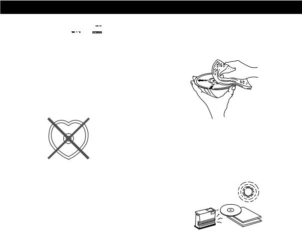
• Do not use any non standard shaped CD (heart, etc.) available on the market, because it may damage the unit.
• Do not use a CD with tape, seals, or paste on it, because damage to the unit may result.
• Compact discs are not affected by small particles of dust or fingerprints on their playing surface, but even so they should be kept clean. Wipe by using a clean, dry cloth.
Do not wipe with a circular motion; wipe straight outward from the center.
•Do not try to clean the disc’s surface by using any type of disc cleaner, record spray, anti-static spray or liquid, or any other chemical-based liquid, because such substances might irreparably damage the disc’s surface.
•Do not expose discs to direct sunlight, high temperature or high humidity for a long period of time, because these might warp or otherwise damage the disc.
No!
E-2
|
|
|
PREPARATIONS |
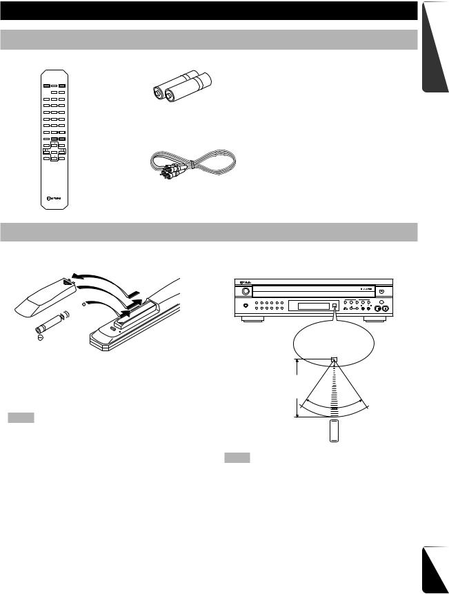
Supplied Accessories |
|
||
Remote Control Transmitter |
Batteries (size AA, UM-3, R6) (2) |
||
|
|
OPEN/ |
|
SYNCHRO DIMMER CLOSE |
|
||
|
TEXT/ |
PEAK |
|
|
TIME |
|
|
TAPE |
CLEAR PROG |
|
|
1 |
2 |
3 |
|
4 |
5 |
6 |
|
7 |
8 |
9 |
|
0 |
—10 |
INDEX |
|
MODE |
— OUTPUT LEVEL — |
RCA Pin Cable |
|
DISC SCAN |
DISC SKIP |
||
REPEAT |
|
RANDOM |
|
STARTED GETTING
Remote Control Transmitter
■ Battery installation |
■ Remote control transmitter opera- |
1 |
tion range |
3

 2
2
NATURAL SOUND COMPACT DISC PLAYER |
■ Battery replacement
If you find that the remote control transmitter must be used closer to the main unit, the batteries are weak. Replace both batteries with new ones.
Notes
•Use only AA, R6, UM-3 batteries for replacement.
•Be sure the polarities are correct. (See the illustration inside the battery compartment.)
•Remove the batteries if the remote control transmitter will not be used for an extended period of time.
•If batteries leak, dispose of them immediately. Avoid touching the leaked material or letting it come in contact with clothing, etc. Clean the battery compartment thoroughly before installing new batteries.
Remote control sensor
Within approximately 6 m (19.7 feet)
30 |
° |
° |
30 |
||
|
|
Notes
•There should be no large obstacles between the remote control transmitter and the main unit.
•If the remote control sensor is directly illuminated by strong lighting (especially an inverter type of fluorescent lamp, etc.),
it might cause the remote control transmitter not to work correctly. In this case, reposition the main unit to avoid direct lighting.
English
E-3
PREPARATIONS
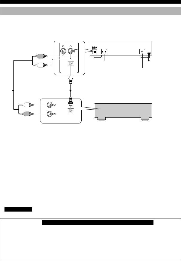
Connections
Never plug in this unit and other components until all connections are completed.
•Before making any connections, switch OFF the power to the unit and the amplifier or other components.
•Connections should be made to the correct input terminals of the amplifier or other components.
•If the placement of this unit causes noise in other equipment, such as a tuner, separate them from each other.
1 Pin cable (included)
|
LINE OUT |
R |
L |
|
1 |
|
1 |
|
|
REMOTE CONTROL |
To AC outlet |
|
|
(CDC-685 U.S.A., |
|
|
OPTICAL |
|
|
|
Canada and Australia |
VOLTAGE SELECTOR |
|
|
DIGITAL AUDIO OUT |
||
|
models only) |
(General model only) |
|
|
|
||
|
2 Optical fiber cable |
|
|
|
(not included) |
|
|
|
L |
|
|
|
R |
|
|
|
OPTICAL |
|
|
CD |
DIGITAL IN |
|
|
ANALOG IN |
Amplifier |
|
Choose one of the ways listed below to connect this unit to your amplifier.
When the LINE OUT (analog) terminals of this unit are used (1)
•Be sure that the left (L) and right (R) LINE OUT terminals are connected to the corresponding (left and right) terminals of the amplifier or other components.
•Connect the LINE OUT terminals to the “CD” (or “AUX”) terminals of the amplifier. For additional details concerning these connections, refer to the operation instructions for the amplifier being used.
•The LINE OUT terminals of this unit are numbered !. When connecting this unit with a YAMAHA amplifier or receiver whose terminals on the rear panel are numbered as !, @, #, etc., connect the LINE OUT terminals of this unit to the input terminals numbered ! on the rear of the amplifier or receiver.
When the DIGITAL AUDIO OUT (OPTICAL) terminal of this unit is used (2)
•Before using this terminal, remove the terminal’s cover by pulling it.
•Make the connection from this terminal to the optical input terminal of an amplifier by using a commercially available optical fiber cable.
*Be sure to use a high quality optical fiber cable. Other cables might not function correctly.
•Be sure to attach the terminal cover when this terminal is not being used in order to protect the terminal from dust.
•CDC-685 only
Set the level of signals output into an amplifier to max. by using the OUTPUT LEVEL –/+buttons.
For Custom Installer For U.S.A., Canada and Australia models of CDC-685 only REMOTE CONTROL (IN, OUT) terminals
These terminals are used for custom installation system. When this unit is connected to the components for custom installation system, you can operate this unit with the system remote control.
Connect the REMOTE CONTROL IN terminal of this unit to the output terminal of the central controller for custom installation system.
By connecting the REMOTE CONTROL OUT terminal of this unit to the REMOTE CONTROL IN terminal of the other component, you can also operate it with the system remote control. In this way, up to 6 components can be connected in series.
E-4
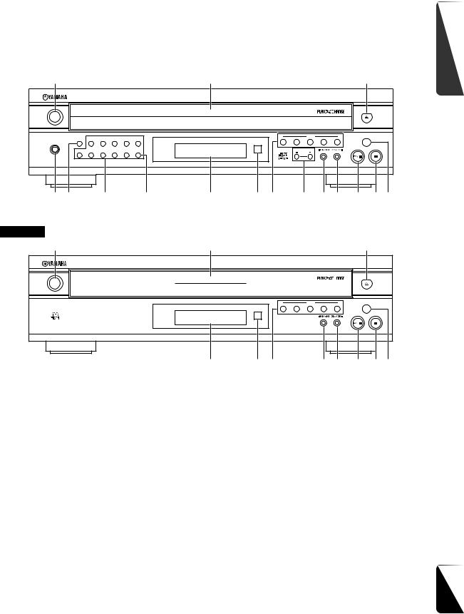
Front Panel |
CONTROLS AND FUNCTIONS |
|
GETTING |
|
|
|
|
|
|
|
|
|
|
STARTED |
|
|
|
|
|
|
|
|
|
|
CDC-685 |
|
|
|
|
|
|
|
|
|
1 |
2 |
3 |
|
|
NATURAL SOUND COMPACT DISC PLAYER
POWER |
|
|
|
|
|
|
|
|
|
|
|
|
|
|
|
|
|
|
|
|
|
DISC |
|
|
PLAYXCHANGE |
PROG |
1 |
2 |
3 |
4 |
5 |
|
|
|
|
|
|
|
PHONES |
|
|
|
|
|
|
1 |
2 |
3 |
4 |
5 |
|
+10 |
6 |
7 |
8 |
9 |
0 |
|
|
|
OUTPUT LEVEL |
|
|
|
|
|
|
|
|
|
|
||||||
|
|
|
|
|
PEAK |
|
|
|
|
|
|
|
4 5 6 |
|
|
7 |
8 |
9 0 q w e r t y |
|||||||
CDC-585 |
|
|
|
|
|
|
|
|
|
|
|
|
1 |
|
|
|
|
|
2 |
|
|
|
|
|
3 |
NATURAL SOUND COMPACT DISC PLAYER |
|
|
|
|
|
|
|
|||||
POWER |
|
|
|
|
|
|
|
|
|
|
|
|
|
|
|
|
|
|
|
|
|
DISC |
|
|
PLAYXCHANGE |
|
|
|
|
|
|
|
1 |
2 |
3 |
4 |
5 |
|
|
|
|
|
|
|
8 |
9 0 |
|
|
w e |
r t y |
|
1 POWER .......................................................... P.8,9 |
9 Remote control sensor |
|
|
|||||||||
2 Disc tray .......................................................... P.8,9 |
0 DISC-select ....................................................... P.8 |
|||||||||||
3 v (Open/Close) |
|
|
|
|
|
|
q OUTPUT LEVEL –/+.................................... P.15 |
|||||
4 PHONES jack ................................................. P.15 |
w t/e (Skip/Search) |
|
|
|||||||||
5 PROG ......................................................... P.12,18 |
e r/y (Skip/Search) |
|
|
|||||||||
6 Numeric buttons ............................................... P.10 |
r w/d (Play/Pause) |
|
|
|
||||||||
7 PEAK ......................................................... P.16,21 |
t a (Stop) |
|
|
|
|
|
||||||
8 Display panel ..................................................... P.7 |
y PLAYXCHANGE ............................................. P.9 |
|||||||||||
|
|
|
|
|
|
|
|
|
|
|
|
English |
|
|
|
|
|
|
|
|
|
|
|
|
E-5 |
Loading...