

Page 1
Page 2
SPECIAL MESSAGE SECTION
PRODUCT SAFETY MARKINGS: Yamaha electronic
products may have either labels similar to the graphics
shown below or molded/stamped facsimiles of these graphics on the enclosure. The explanation of these graphics appears on this page. Please observe all cautions indicated on
this page and those indicated in the safety instruction section.
CAUTION
RISK OF ELECTRIC SHOCK
DO NOT OPEN
CAUTION: TO REDUCE THE RISK OF ELECTRIC SHOCK.
DO NOT REMOVE COVER (OR BACK).
NO USER-SERVICEABLE PARTS INSIDE.
REFER SERVICING TO QUALIFIED SERVICE PERSONNEL.
The exclamation point within the equilateral triangle is intended to alert the user to
the presence of important operating and
maintenance (servicing) instructions in
the literature accompanying the product.
The lightning flash with arrowhead symbol within the equilateral triangle is intended to alert the user to the presence of
uninsulated “dangerous voltage” within
the product’s enclosure that may be of
sufficient magnitude to constitute a risk of
electrical shock.
ENVIRONMENTAL ISSUES: Yamaha strives to produce
products that are both user safe and environmentally
friendly. We sincerely believe that our products and the
production methods used to produce them, meet these goals.
In keeping with both the letter and the spirit of the law, we
want you to be aware of the following:
Battery Notice: This product MAY contain a small nonrechargable battery which (if applicable) is soldered in
place. The average life span of this type of battery is approximately five years. When replacement becomes necessary, contact a qualified service representative to perform
the replacement.
Warning: Do not attempt to recharge, disassemble, or incinerate this type of battery. Keep all batteries away from children. Dispose of used batteries promptly and as regulated by
applicable laws. Note: In some areas, the servicer is required
by law to return the defective parts. However, you do have
the option of having the servicer dispose of these parts for
you.
Disposal Notice: Should this product become damaged
beyond repair, or for some reason its useful life is considered to be at an end, please observe all local, state, and federal regulations that relate to the disposal of products that
contain lead, batteries, plastics, etc.
NOTICE: Service charges incurred due to lack of knowledge relating to how a function or effect works (when the
unit is operating as designed) are not covered by the manufacturer’s warranty, and are therefore the owners responsibility. Please study this manual carefully and consult your
dealer before requesting service.
IMPORTANT NOTICE: All Yamaha electronic products
are tested and approved by an independent safety testing
laboratory in order that you may be sure that when it is properly installed and used in its normal and customary manner,
all foreseeable risks have been eliminated. DO NOT modify
this unit or commission others to do so unless specifically
authorized by Yamaha. Product performance and/or safety
standards may be diminished. Claims filed under the expressed warranty may be denied if the unit is/has been modified. Implied warranties may also be affected.
SPECIFICATIONS SUBJECT TO CHANGE: The information contained in this manual is believed to be correct at
the time of printing. However, Yamaha reserves the right to
change or modify any of the specifications without notice or
obligation to update existing units.
92-469 1
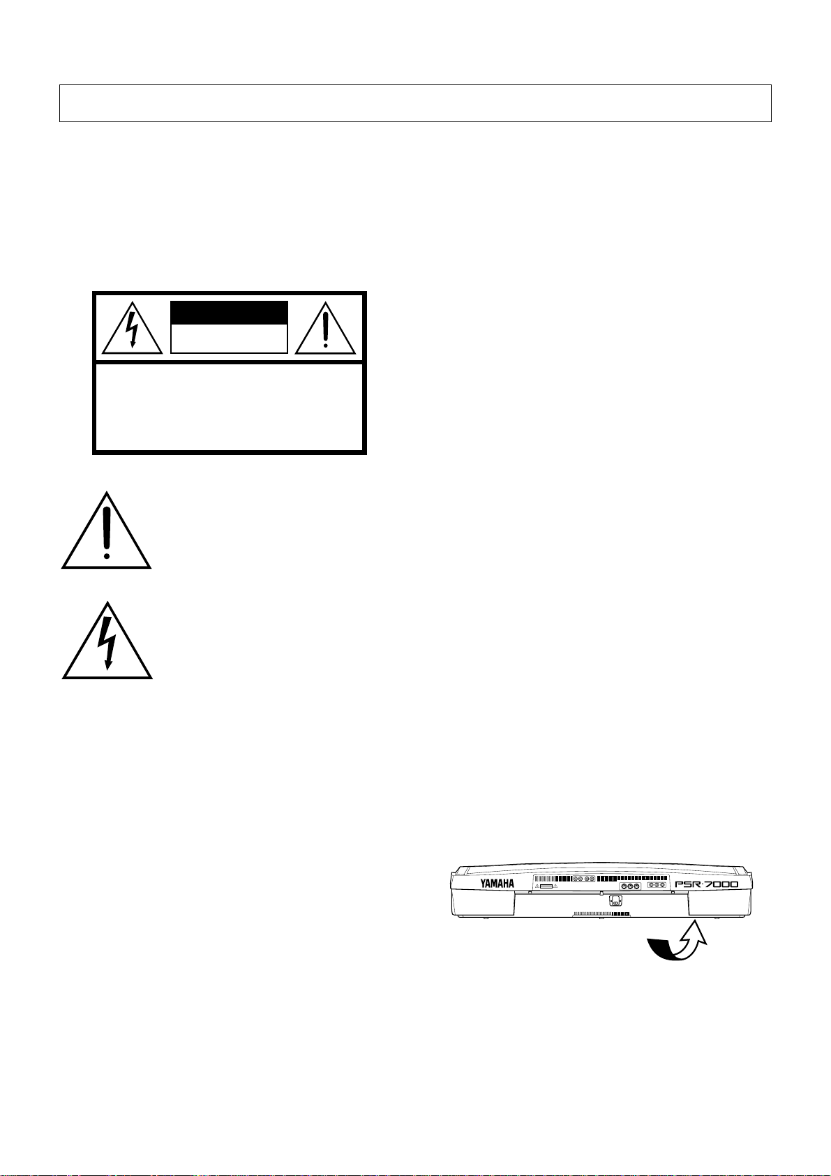
NAME PLATE LOCATION: The graphic below indicates
the location of the name plate. The model number, serial
number, power requirements, etc., are located on this plate.
You should record the model number, serial number, and the
date of purchase in the spaces provided below and retain this
manual as a permanent record of your purchase.
AUX OUT
AVIS:
RISQUE DE CHOC ELECTRIQUE NE PAS OUVRIR.
AUX IN
R L/L+R
WARNING:
TO REDUCE THE RISK OF FIRE OR ELECTRIC SHOCK,
DO NOT EXPOSE THIS PRODUCT TO RAIN OR MOISTURE.
R L/L+R
CAUTION
RISK OF ELECTRIC SHOCK
DO NOT OPEN
MIDI
FOOT SWITCH
FOOT VOLUME
OUT
IN
THRU
12
AC INLET
Model _____________________________________
Serial No. __________________________________
Purchase Date ______________________________
Page 3
Owner’s Manual
English
Bedienungsanleitung
Mode d’emploi
Deutsch
Français
Page 4
Congratulations!
You are the pr oud owner of an extraordinary electronic keyboar d. The Yamaha
PSR-7000 PortaTone combines the most advanced AWM tone generation technology with state-of-the-art digital electronics and featur es to give you stunning sound
quality with maximum musical enjoyment. The advanced Auto Accompaniment and
One Touch Setting features, in particular, are brilliant examples of how Yamaha
technology can significantly expand your musical horizons. A new large-size
graphic display and easy-to-use interface also greatly enhance the operability of
this advanced instrument.
In order to make the most of your PortaTone’s features and vast performance
potential, we urge you to r ead the manuals thor oughly while trying out the various
features described. Keep the manuals in a safe place for later reference.
Contents
Taking Care of Your PortaTone 2
Floppy Disks & the Disk Drive ...........3
Panel Controls 4
Connections & Music Stand 6
The Demonstration 8
The Random & Single Demo Play
Modes
...................................................... 9
The PSR-7000 Display &
Display-based Controls 10
The Display & Multi-function
Controls
................................................10
■ The [MIXER] Button ........................10
■ The [LIST HOLD] Button ................. 11
■ The [LCD CONTRAST] Control ...... 11
■ The 5-language Help Function........ 11
Playing the PSR-7000 12
■ Before You Begin............................. 12
Selecting & Playing Voices ............. 12
Using the Organ Flute Voices.........16
■ FOOTAGE.......................................16
■ VOLUME & ATTACK ...................... 17
■ NAME & ROTARY SPEAKER ........ 17
■ Using the Rotary Speaker Effect..... 18
Keyboard Percussion ....................... 19
Changing the “L” Split Point .......... 20
Transposition, Tuning, &
Octave Change 21
TRANSPOSE & TUNE........................21
OCTAVE CHANGE..............................22
Using the Accompaniment
Section 23
■ Fade-ins and Fade-outs ..................30
■ Accompaniment Volume .................30
■ The Auto Mute Function.................. 30
Changing the “A” Split Point ..........31
The Chord Assist Function ............. 32
The Arranger Buttons ....................... 34
One Touch Setting 35
■ THE TEMPO SET FUNCTION........36
Expression & Effects 37
■ Harmony..........................................37
■ Sustain ............................................37
■ Touch Response .............................38
■ Reverb.............................................38
■ Chorus.............................................39
■ DSP Effects..................................... 39
■ Left Hold.......................................... 39
■ Pitch Bend Wheel............................40
■ Modulation Wheel ........................... 40
■ Digital Equalizer ..............................41
The Multi Pads 42
The PHRASE/CHORD Mode ............ 42
The PHRASE Pads (pads 1 … 4)......42
■ Recording Phrases..........................43
■ Phrase Playback .............................44
The CHORD Pads (pads 5 … 8) ....... 44
■ Recording Chords ...........................44
■ Chord Playback............................... 45
■ The Repeat & Chord Match Settings46
● REPEAT ...................................... 46
● CHORD MATCH ......................... 46
The PERCUSSION Mode .................. 47
■ Assigning Different Instruments
To the PERCUSSION Pads ............47
■ Playing the Percussion Pads .......... 48
Registration Memory 49
Registering the Panel Settings.......49
Entering a Registration Name..........50
Recalling the Registered Panel
Settings
.................................................51
The Freeze Function.......................... 52
The Freeze Group Settings .............. 52
Song Playback & Recording 53
Song Playback .................................... 53
■ Pause, Fast Forward & Reverse .....54
Chain Playback ................................. 55
Volume & Mute/Solo Settings ..........56
Song Recording.................................. 58
Quick Record.....................................60
■ THE TRACK INDICATORS.............62
■ TRACK DELETE .............................62
■ PLAYBACK .....................................62
■ EXITING.......................................... 62
Chord Step Recording ...................... 63
■ DELETING EVENTS....................... 64
Quick Record Mode Edit Functions ...
■ SONG DELETE...............................65
Multitrack Record..............................66
■ THE TRACK INDICATORS.............68
■ TRACK DELETE .............................68
■ RECORDING & EFFECTS ............. 68
■ PLAYBACK .....................................69
■ EXITING.......................................... 69
Punch-In Recording .......................... 69
Track Volume Control.......................72
Multitrack record Mode
Edit Functions ...................................72
■ QUANTIZE ......................................72
■ TRACK COPY/MIX ......................... 73
■ INITIAL EDIT................................... 74
■ SONG DELETE...............................74
65
Page 5

Custom Accompaniment 75
Effects ................................................79
■ REVERB DEPTH ............................79
■ CHORUS TYPE & DEPTH..............80
■ PAN................................................. 80
Edit .....................................................81
■ QUANTIZE ...................................... 81
■ COPY ..............................................81
■ REMOVE EVENT............................82
Store/Clear......................................... 83
■ STORE............................................ 83
■ CLEAR CUSTOM STYLE ...............83
Custom Voice Edit 84
Engaging the Easy/Full Edit Mode 84
■ EXITING.......................................... 84
The Easy Edit Parameters ............... 85
EDIT .................................................... 85
■ NAME.............................................. 85
■ PAN................................................. 85
■ VIBRATO ........................................ 85
■ TONE ..............................................86
■ ENVELOPE..................................... 86
STORE/CLEAR ..................................87
■ STORE............................................ 87
■ CLEAR CUSTOM VOICE ............... 87
The Full Edit Parameters..................88
E1:BASIC ...........................................88
■ NAME.............................................. 88
■ WAVE (except for the DRUM KITS) ........... 88
■ TUNE (except for the DRUM KITS)............89
■ VOLUME (except for the DRUM KITS) ......89
■ KEY ON DELAY
(except for the DRUM KITS) ...................... 89
■ PAN................................................. 89
E2:CONTROLLER ............................. 89
■ PITCH BEND WHEEL.....................89
■ MODULATION WHEEL .................. 90
■ INITIAL TOUCH CURVE.................90
■ AFTER TOUCH...............................90
E3:ENVELOPE ................................... 91
■ AMPLITUDE ENVELOPE ...............91
■ FILTER............................................ 92
E4:EFFECTS ......................................93
■ LFO .................................................93
■ DELAY VIB......................................93
■ REVERB DEPTH ............................93
■ CHORUS DEPTH ........................... 93
■ DSP EFFECT.................................. 93
■ LEAD EFFECT................................ 94
STORE/CLEAR ..................................94
■ STORE............................................ 94
■ CLEAR CUSTOM VOICE ............... 94
The Drum Kit Edit Mode ...................95
Disk Operations 96
Load From Disk .................................. 96
Save To Disk........................................ 98
Rename File/Song .............................. 99
Delete File/Song................................101
Format FD........................................... 102
Song Copy.......................................... 102
HD Utility............................................. 104
■ DIRECTORY EDIT........................ 104
● RENAME ................................... 104
● MAKE ........................................104
● DELETE .................................... 105
■ HD FORMAT................................. 105
■ CHECK..........................................105
The PSR-7000 “Functions” 106
General Function Selection &
Editing Procedure
■ The [EXIT] Button..........................107
............................106
F1: Scale (Arabic)/Voice Part 108
■ SCALE (ARABIC)..........................108
■ VOICE PART ................................ 108
● SCALE CURVE ......................... 108
● PART TUNE .............................. 109
● OCTAVE ................................... 109
● PAN ........................................... 109
F2: Split Point/ABC Mode/
Multi Pad 110
■ SPLIT POINT/ABC MODE ............110
● SPLIT POINT ............................ 110
● ABC MODE ...............................110
■ MULTI PAD ...................................111
● REPEAT .................................... 111
● CHORD MATCH ....................... 111
F3: Controller 112
■ FOOT CONTROLLER...................112
● VOLUME ...................................112
● SW1 (FOOTSWITCH 1) &
SW2 (FOOTSWITCH 2) ............ 112
■ PANEL CONTROLLER................. 114
● SUSTAIN BUTTON ................... 114
● PITCH BEND WHEEL............... 114
● MODULATION WHEEL.............114
● INITIAL TOUCH ........................ 115
● AFTER TOUCH......................... 115
F4: Style Revoice 116
● VOLUME OFFSET .................... 116
● VOICE .......................................116
● REVERB DEPTH ...................... 117
● CHORUS DEPTH......................117
F5:
Reverb/Chorus/DSP Effect
■ REVERB TYPE & DEPTH ............ 118
● REVERB TYPE .........................118
● REVERB PARAMETER EDIT ... 119
● REVERB DEPTH ...................... 119
■ CHORUS DEPTH ......................... 120
■ DSP EFFECT TYPE & DEPTH..... 120
● DSP EFFECT TYPE ................. 120
●
DSP EFFECT PARAMETER EDIT .
● DSP EFFECT DEPTH............... 121
118
121
F6: Harmony/Registration 122
■ HARMONY.................................... 122
■ REGISTRATION ...........................122
● NAME ........................................ 122
● FREEZE GROUP SETTING ..... 122
F7: Utility 123
■ MEMORY BACKUP ......................123
● MEMORY BACKUP .................. 123
● DISPLAY - MIDI BANK SEL. &
PROG. CHANGE #, TIME......... 123
■ RECALL PRESET DATA ..............123
F8: MIDI 124
SYSTEM .............................................. 124
■ LOCAL CONTROL........................ 124
■ CLOCK & TRANSPOSE ...............125
● CLOCK ...................................... 125
● TRANSPOSE ............................125
■ MESSAGE SWITCH .....................125
● START/STOP............................ 125
● EXCLUSIVE ..............................126
TRANSMIT.....................................126
● TRANSMIT MONITOR .............. 126
● CHANNEL .................................126
● PART.........................................126
● NOTE, CONTROL CHANGE, PRO-
GRAM CHANGE, & PITCH BEND
SWITCH ....................................127
RECEIVE ....................................... 128
● RECEIVE MONITOR.................128
● CHANNEL .................................128
● MODE .......................................128
● NOTE, CONTROL CHANGE, PRO-
GRAM CHANGE, & PITCH BEND
SWITCH ....................................128
PANEL CONTROL ........................ 129
● OCTAVE ................................... 129
● NOTE ........................................ 129
● TYPE SELECT & SUB .............129
Troubleshooting ...............................131
Index .................................................... 132
Voice List ............................................ 134
Percussion Kit List .......................... 138
Style List .............................................139
Setup Parameters.............................140
Fingering Chart ................................. 144
The DSP Effects & Parameters.....153
MIDI Implementation Chart............ 159
MIDI Data Format.............................. 162
Sample Data Disks........................... 167
Specifications....................................168
Page 6
Taking Care of Your PortaTone
Your PortaTone will give you years of playing pleasure if you follow
the simple rules given below:
■ Location
Do not expose the instrument to the following conditions
to avoid deformation, discoloration, or more serious damage.
● Direct sunlight (e.g. near a window).
● High temperatures (e.g. near a heat source, outside , or
in a car during the daytime).
● Excessive humidity.
● Excessive dust.
● Strong vibration.
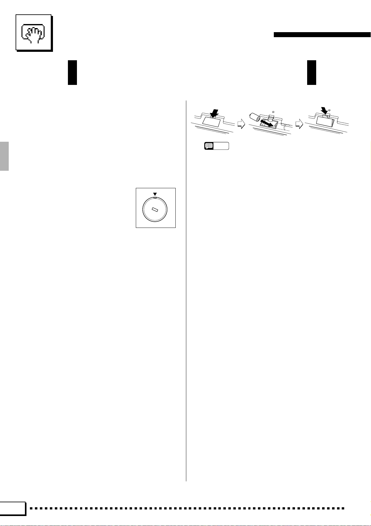
■ Power Supply
● In some areas the PSR-7000 will
have a voltage selector on the bottom panel. Make sure that the voltage selector is set for the AC mains
voltage in your area. The voltage
selector can be set (rotated) by using a screwdriver. If in doubt, contact your Yamaha dealer.
● T urn the power switch OFF when the instrument is not
in use. (The PSR-7000 uses a ver y small amount of
power to maintain the internal memory contents even
when no batteries are installed and the power is turned
off.)
● The power supply cord should be unplugged from the
AC outlet if the instrument is not to be used for an
extended period of time.
● Unplug the instrument during electric storms.
● Avoid plugging the instrument into the same AC outlet
as appliances with high power consumption, such as
electric heaters or ovens. Also avoid using multi-plug
adapters since these can result in reduced sound
quality, operation errors, and possibly damage.
■ Memory Backup Batteries
The PSR-7000 requires four 1.5 V C size (LR14) batteries
for memory backup power. If no backup batteries are
installed, the memory contents will be lost when then
instrument is unplugged from the AC mains supply . Please
use alkaline batteries. The av erage life of a set of alkaline
batteries is about 12 months.
1. Open Battery Compartment Cover
Open the battery compartment cover — located on the
instrument’s bottom panel — by pressing on the two
latches on the cover and pulling outward, as shown in
the illustration.
2. Insert Batteries
Insert the four batteries, being careful to follow the
polarity markings on the bottom panel.
3. Replace Cover
Replace the compartment cover, making sure that it
locks firmly in place.
110V
240V
1
3
220V
NOTES
• Never mix old and new, or different type of batteries!
• To prevent damage due to battery leakage, it is a good idea
to remove the batteries from the PSR-7000 (after saving any
important data to disk) if it is not to be used an extended
period of time. (YAMAHA is not responsible irretrievable
internal data.)
0
V
■
Turn Power OFF When Making Connections
● To avoid damage to the instrument and other devices
to which it is connected (a sound system, for example),
turn the power switches of all related devices OFF prior
to connecting or disconnecting audio and MIDI cables.
■ Handling and Transport
● Never apply excessive force to the controls, connec-
tors or other parts of the instrument.
● Always unplug cables by gripping the plug firmly , not by
pulling on the cable.
● Disconnect all cables before moving the instrument.
● Physical shocks caused by dropping, bumping, or
placing heavy objects on the instrument can result in
scratches and more serious damage.
■ Cleaning
● Clean the cabinet and panel with a dry soft cloth.
● A slightly damp cloth may be used to remove stubborn
grime and dirt.
● Never use cleaners such as alcohol or thinner.
● Avoid placing vinyl objects on top of the instrument
(vinyl can stick to and discolor the surface).
■ Electrical Interference
● This instrument contains digital circuitry and ma y cause
interference if placed too close to radio or television
receivers. If this occurs, move the instrument further
away from the affected equipment.
■ Data Backup
● Save all important data to disk before turning off for
longer periods.
● Internal data (e.g. Registration data) is retained in
memory even if the power switch is turned OFF when
backup batteries are installed as described above. If
you do not intend to use the PSR-7000 for an e xtended
period of time, it is a good idea to unplug the instrument
from the AC outlet and remove the batteries.
2
Page 7
Taking Care of Your PortaTone
● Internal memor y data can be corr upted due to incorrect operation. Be sure to “save” important data to a
floppy disk frequently so you hav e a backup to revert to
if something happens to damage the data in memory.
Also note that magnetic fields can damage data on the
disk, so it is advisable to make a second back-up cop y
of disks that contain very important data, and keep
backup disks in a safe place away from stray magnetic
fields (i.e. a wa y from speak ers, appliances containing
motors, etc.).
Floppy Disks & the Disk Drive
■ Type of Disk
Use only 3.5-inch 2DD or 2HD floppy disks.
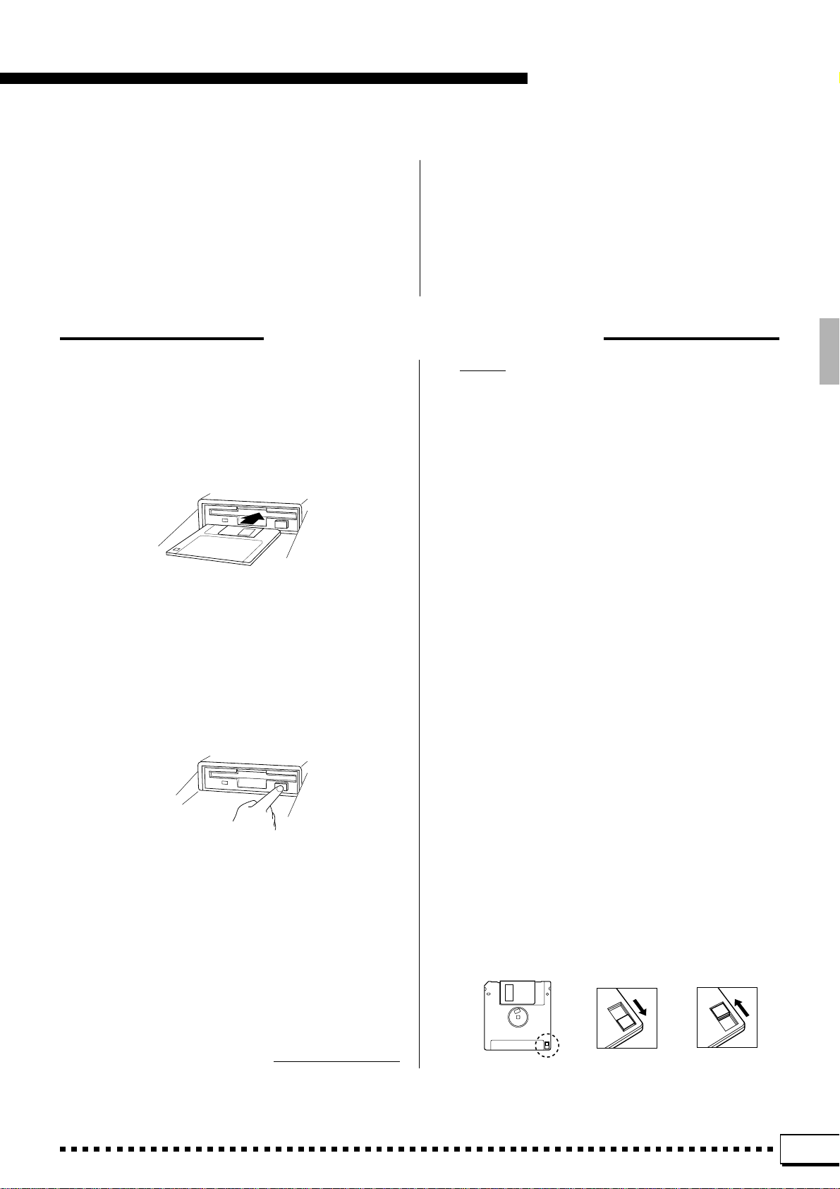
■ Disk Insertion & Removal
● To inser t a floppy disk in the disk drive, hold the disk
with the label side facing up and the sliding shutter
facing the disk drive door , then insert carefully until the
disk clicks into place.
● T o remove a flopp y disk from the disk drive, make sure
the “DISK IN USE” light is not lit and press the disk
eject button firmly as far as it will go and then, when the
disk is full ejected, remove it by hand.
If the eject button is only partially pressed or pressed
too quickly the eject mechanism may not function
properly , leaving the disk stuck halfway . Do not attempt
to remove the disk forcefully if this happens, since
excess force can damage the disk and/or the drive
mechanism. Try either pressing the eject b utton carefully again, or push the disk all the way back into the
drive and repeat the eject procedure.
■ Service and Modification
● The PSR-7000 contains no user serviceable parts.
Opening it or tampering with it in anyway can lead to
irreparable damage and possibly electric shock. Ref er
all servicing to qualified YAMAHA personnel.
ing Disk to clean the head about once a month. Ask y our
Yamaha dealer about the available of head-cleaning
disks.
■ Floppy Disk Handling & Storage
The actual recording medium inside a floppy disk has a
fine coating of magnetic particles in which the data is
“stored”. To protect this coating as well as the disk drive’s
delicate read-write head, please observe the following:
● Always keep floppy disks in their case when they are
not in use. Never place heavy objects on a disk or bend
the disk in any way. Also k eep disks a wa y from liquids
and dust.
● Never open the disk’s shutter and touch the exposed
surface of the disk.
● Keep floppy disks away from strong magnetic fields
such as those produced by television sets, speakers,
motors, etc.
● Never leave floppy disks in areas exposed to strong
direct sunlight, excessively high or low temper ature, or
high humidity.
● Never use a floppy disk with a defor med shutter or
housing.
● Do not attach anything other than the provided labels
to a floppy disk. Also make sure that labels are attached in the proper location.
● Never attempt to remove a flopp y disk during a record
or playback operation!! This can corrupt the data on the
disk, and actually damage the disk drive!
● Be sure to remove the floppy disk from the disk drive
before turning off the power. A floppy disk left in the
drive for extended periods can easily pick up dust and
dirt that can cause data read/write errors.
■ Clean the Read/Write Head Regularly
This instrument employs a precision magnetic read/write
head which, after an extended period of use, will pick up
a layer of magnetic particles from the disks used that will
eventually cause read and write errors. To maintain the
disk drive in optimum working order we recommend that
you use a commercially-availab le
Dry-type Head Clean-
YAMAHA is not responsible for damage caused by improper handling or operation.
■ Protecting Your data
● To prevent accidental erasure of important data you
have saved to floppy disk, be sure to slide the disk’s
write-protect tab to the “write protect” position (the tab
window should be open). When this is done the disk
cannot be written to.
● Make regular backup copies of important data to a
separate floppy disk, and keep your bac kup disks in a
separate, safe place.
● T o ensure the safety of y our data (and of the disk drive
itself) always use floppy disks from a well-known,
reliable manufacturer. “No-brand” disks can cause
trouble.
Write protected Write enabled
YAMAHA provides no guarantee against disk damage.
3
Page 8
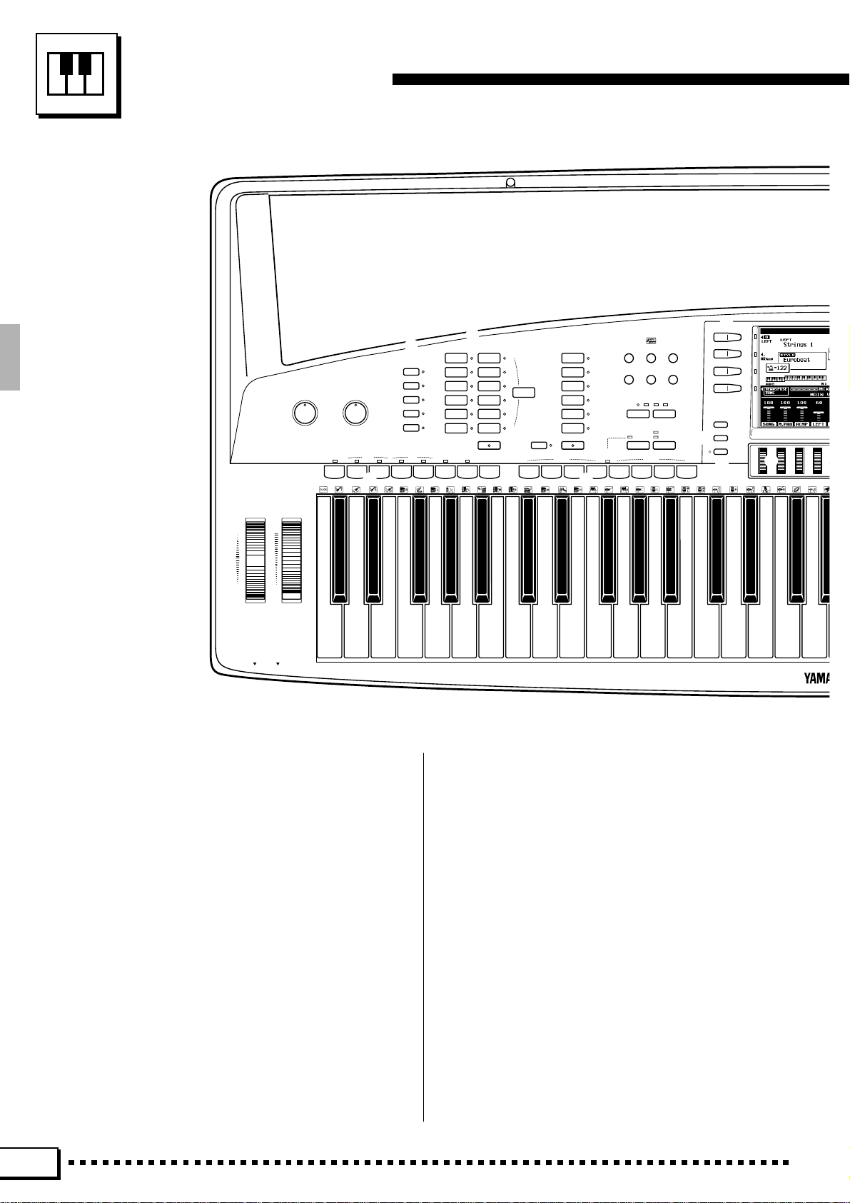
Panel Controls
a s
PITCH BEND MODULATION
UP
MAX
DOWN MIN
PHONES MIC
MASTER VOLUME
MIN •• MAX
3
MIC VOLUME
MIN •• MAX
4
INTRO/
FADE
FILL to
IN / OUT
ABAB
9
ACCOMPANIMENT DIRECTOR
5
ARRANGER
PHRASE
PAD
CHORD
BASS
RHYTHM
MAIN
ACCOMPANIMENT
ROCK /
ROCK’N’ROLL
POP / BEAT
BALLAD
DANCE
DISCO
RHYTHM &
BLUES
8
SYNCHRO
ENDING/
START
rit.
6
AUTO BASS CHORD
JAZZ
LATIN
COUNTRY&
WESTERN
MARCH/
WALTZ
BALLROOM
CUSTOM
STYLE
START/STOP
0
LEFT ORCHESTRA
PIANO/
ORGAN
STRINGS/
7
ONE TOUCH
SETTING
!
CHOIR
BRASS/
WOODWIND
SYNTH/
PAD
GUITAR/
PERCUSSIVE
CUSTOM
VOICE
LEFTLEFT HOLD
PHRASE
12345678
(
PHRASE/CHORD
PLAYING
MULTI PAD
*
@#$
SONG
CUSTOM
FUNCTION
PLAY
VOICE EDIT
SONG
CUSTOM
RECORD
%
ACCOMP. REC
^ &
TEMPO
–
REC/STOP
CHORD
DISK
+
PERCUSSION
PHRASE/CHORD
e
w
r
q
DIGITAL
EQUALIZER
MIXER
LIST
HOLD
)
t
1 POWER Button .......................................... page 8
2 DEMO Button............................................. page 8
3 MASTER VOLUME Control........................ page 8
4 MIC VOLUME Control ................................ page 6
5 ARRANGER Buttons ............................... page 34
PHRASE, PAD, CHORD, BASS, RHYTHM
6 ACCOMPANIMENT Buttons .................... page 26
7 ONE TOUCH SETTING Button................ page 35
8 AUTO BASS CHORD Button ................... page 23
9 ACCOMPANIMENT DIRECTOR Buttons
........................................................pages 27 – 30
FADE IN/OUT, INTRO/FILL to A/B, MAIN A/B,
ENDING/rit., SYNCHRO START, START/STOP
4
0 LEFT ORCHESTRA Buttons ............pages 13, 14
! LEFT HOLD Button.................................. page 39
@ SONG PLAY Button ................................. page 53
# CUSTOM VOICE EDIT Button ................. page 84
$ FUNCTION Button ................................. page 106
% SONG RECORD Button .......................... page 58
^ CUSTOM ACCOMP. REC Button............. page 75
& DISK Button ............................................. page 96
* TEMPO [–] and [+] Buttons...................... page 26
( MULTI PAD Buttons ................................. page 42
REC/STOP, PHRASE/CHORD-PERCUSSION,
1 — 8
Page 9
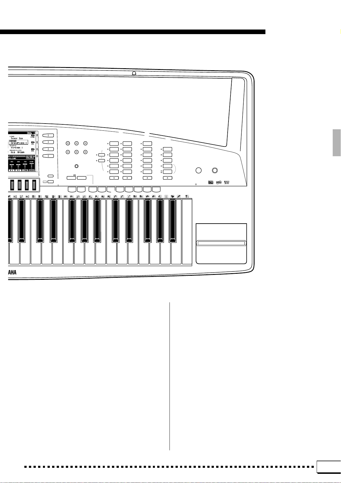
Panel Controls
LANGUAGE
i o p
HARMONY
REVERB
Q
TOUCH
RESPONSE
SUSTAIN
CHORUS
EFFECT
W E
LCD
CONTRAST
Y
DSP
PART SELECT
R 1
R 2
R
y
HELP/
EXIT
u
FREEZE MEMORY
BANK 1~16
–
+
12345678
U I
RIGHT ORCHESTRA
ACCORDION/
PIANO
WORLD
SYNTH/
ORGAN
PAD
SOUND
STRINGS/
EFFECT
CHOIR
SAX/
PERCUSSIVE
WOODWIND
TRUMPET/
DRUM KIT
BRASS
GUITAR/
CUSTOM
BASS
VOICE
RIGHT 1
RIGHT 2
REGISTRATION
T
LEAD
TRUMPET/
BRASS
SAX/
WOODWIND
STRINGS/
CHOIR
GUITAR/
BASS
SYNTH/
PERCUSSIVE
CUSTOM
VOICE
LEAD
ORGAN FLUTE
SLOW
FAST
O
COMBI
1~6
COMBI
7~12
COMBI
13~18
ROTARY
SPEAKER
SPEED
ORGAN FLUTE
DISK IN USE
DEMO
PSR-7000
12
POWER
P
) Liquid Crystal Display (LCD).................... page 10
q LCD Buttons............................................. page 10
w DIGITAL EQUALIZER Button ................... page 41
e MIXER Button .......................................... page 10
r LIST HOLD Button ................................... page 11
t LCD dials ................................................. page 10
y HELP/LANGU AGE Button ....................... page 11
u EXIT Button.......................................pages 9, 107
i HARMONY Button ................................... page 37
o SUSTAIN Button ...................................... page 37
p T OUCH RESPONSE Button.................... page 38
Q REVERB Button....................................... page 38
W CHORUS Button ...................................... page 39
E DSP EFFECT Button ............................... page 39
R LCD CONTRAST Control ........................ page 11
T REGISTRATION Buttons ......................... page 49
FREEZE, MEMORY, BANK 1~16 [–] and [+],
1 — 8
Y PART SELECT Buttons............................ page 14
R1, R2
U RIGHT ORCHESTRA Buttons ..........pages 13, 14
I LEAD Buttons ...................................pages 13, 14
O ORGAN FLUTE Buttons .......................... page 16
P Disk Drive....................................pages 53, 58, 96
a PITCH BEND Wheel ................................ page 40
s MODULATION Wheel .............................. page 40
5
Page 10
Connections & Music Stand
PHONES MIC
AUX OUT
AUX IN
R L/L+R
CAUTION
RISK OF ELECTRIC SHOCK
DO NOT OPEN
AVIS: RISQUE DE CHOC ELECTRIQUE NE PAS OUVRIR.
WARNING:
TO REDUCE THE RISK OF FIRE OR ELECTRIC SHOCK,
DO NOT EXPOSE THIS PRODUCT TO RAIN OR MOISTURE.
R L/L+R
1 2
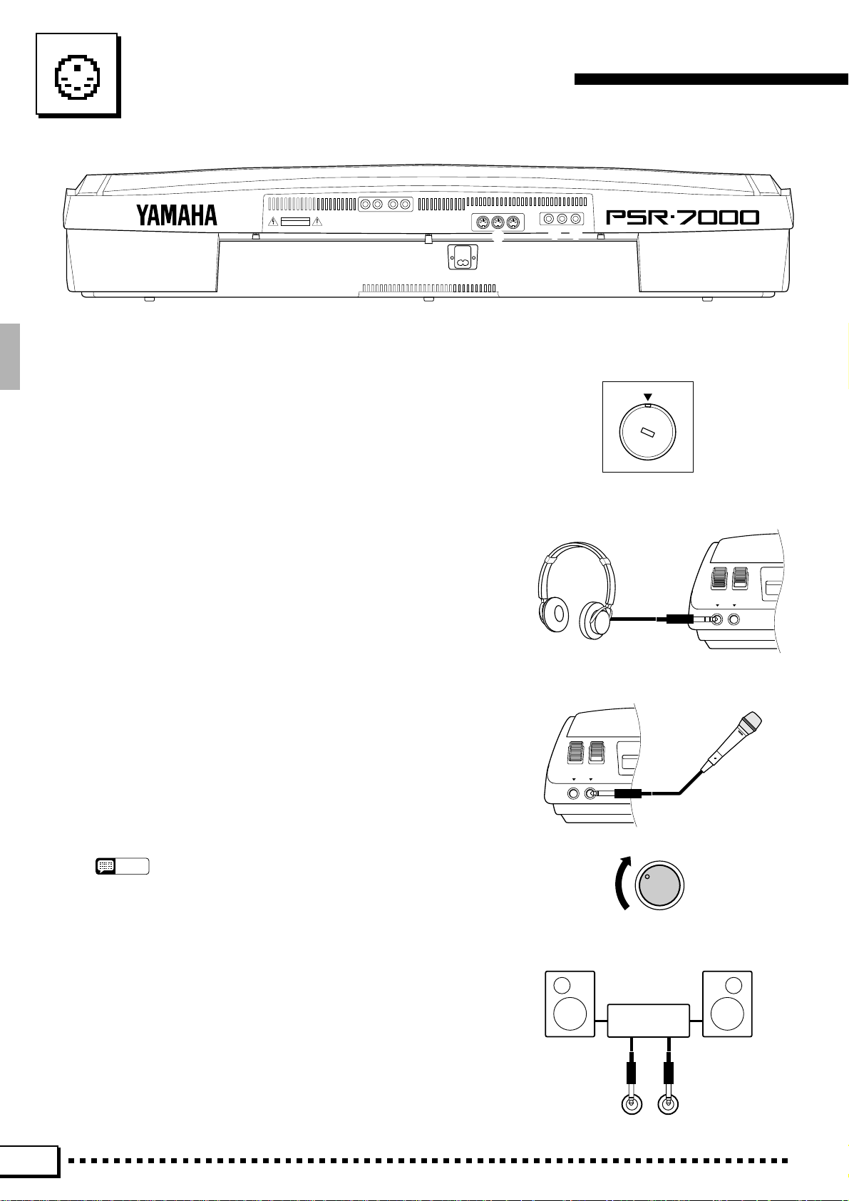
■ Chec k the Voltage (Before you connect the AC cord).........................................................................
In some areas the PSR-7000 will have a voltage selector on the
bottom panel. Make sure that the voltage selector is set for the AC
mains voltage in your area. The voltage selector can be set (rotated)
by using a screwdriver. If in doubt, contact your Yamaha dealer.
AC INLET
MIDI
OUT
IN
5
FOOT SWITCH
THRU
FOOT VOLUME
12
3 4
110V
240V
1
220V
3
0
V
■ The PHONES Jack......................................................................................................................................................................
A standard pair of stereo headphones can be plugged in here for
private practice or late-night playing. The internal stereo speaker
system is automatically shut off when a pair of headphones is plugged
into the PHONES jack.
■ The MIC Jack & MIC VOLUME Control.................................................................................................................
The PSR-7000 includes a microphone (“MIC”) jack into which
just about any standard microphone with a 1/4" phone plug connected
can be plugged (a dynamic microphone with an impedance of 250
ohms is recommended). The microphone sound is amplified and
reproduced via the PSR-7000’s sound system along with the sound of
the internal tone generator. The volume of the microphone sound is
independently controlled by the MIC VOLUME control.
NOTES
• The level of the microphone sound may vary according to the type of
microphone used.
PHONES MIC
MIC VOLUME
MIN •• MAX
1 The AUX OUT L/L+R and R Jac ks.............................................................................................................................
The rear-panel AUX OUT L/L+R and R jacks deliver the output
of the PSR-7000 for connection to a keyboard amplifier, stereo sound
system, a mixing console, or tape recorder. If you will be connecting
Stereo System
the PSR-7000 to a monaural sound system, use only the L/L+R jack.
When a plug is inserted into the L/L+R jack only , the left- and rightchannel signals are combined and delivered via the L/L+R jack so you
don’t lose any of the PSR-7000 sound.
AUX OUT
L/L+RR
6
Page 11
Connections & Music Stand
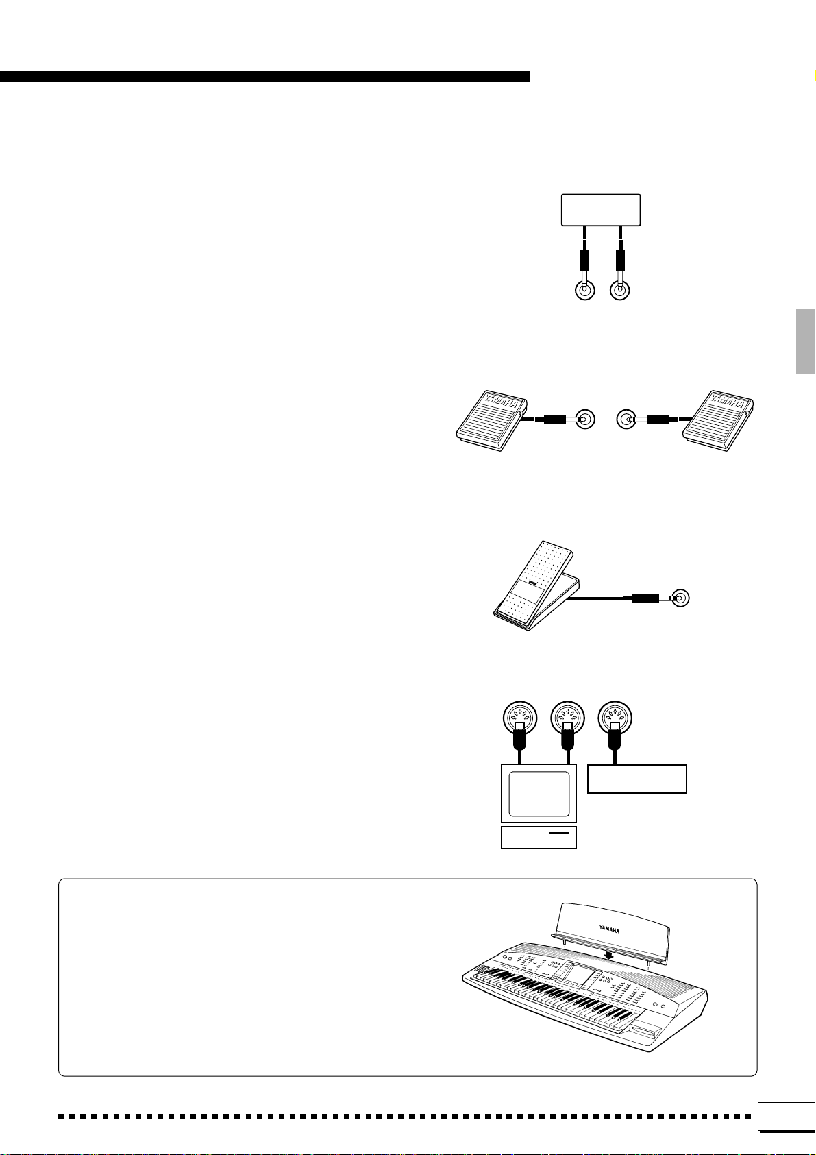
2 The AUX IN L/L+R and R Jacks....................................................................................................................................
The rear-panel AUX IN L/L+R and R jacks accept
input from an external instrument or audio souce. The
signal received at the INPUT jack is mixed with PSR-7000
sound and delivered via the speaker system. When a plug
is inserted into the L/L+R jack only , the signal is delivered
via the both channels.
3 FOOT SWITCH 1 and 2 Jacks.........................................................................................................................................
One or two optional Yamaha FC5 footswitches connected to these jacks can be used to control sustain and a
range of other important functions. Refer to the “FOOT
SWITCH 1” and “FOOT SWITCH 2” functions described
on page 112.
CD Player
AUX IN
L/L+RR
FOOT SWITCH
12
4 FOOT V OLUME Jack................................................................................................................................................................
An optional Yamaha FC7 Foot Controller can be connected to this jack to allow foot volume (expression)
control. The foot controller can be assigned to control
overall volume or the volume of individual accompani-
FOOT VOLUME
ment and/or voices via the “FOOT VOLUME” function —
page 112.
5 MIDI IN, THRU and OUT Connectors ......................................................................................................................
Music
MIDI
OUT THRUIN
Tone Generator
The MIDI IN connector receives MIDI data from an
external MIDI device (such as a MIDI sequencer) which
can be used to control the PSR-7000. The MIDI THRU
connector re-transmits any data received at the MIDI IN
connector, allowing “chaining” of several MIDI instruments or other devices. The MIDI OUT connector transmits MIDI data generated by the PSR-7000 (e.g. note and
velocity data produced by playing the keyboard). More
details on MIDI are provided on page 124.
Computer
The Music Stand
The PSR-7000 is supplied with a music stand that can
be attached to the instrument by inserting it into the holes
at the rear of the speaker panel.
7
Page 12
The Demonstration
DEMO
EXIT
DEMO
POWER
To give you an idea of the PSR-7000’s sophisticated capabilities, it
is programmed with 14 demonstration sequences which can be played
in a number of ways.
Z Switch ON............................................................................................................................................................................................
Plug the AC power cord into a convenient AC
outlet, then press the [POWER] button to turn the
PSR-7000 ON.
DEMO
POWER
X Set an Initial Volume Level ................................................................................................................................................
Set the [MASTER VOLUME] control to a
position about a quarter of the way toward the
highest setting. You can re-adjust the [MASTER
VOLUME] control for the most comfortable overall volume level after playback begins.
MASTER VOLUME
MIN •• MAX
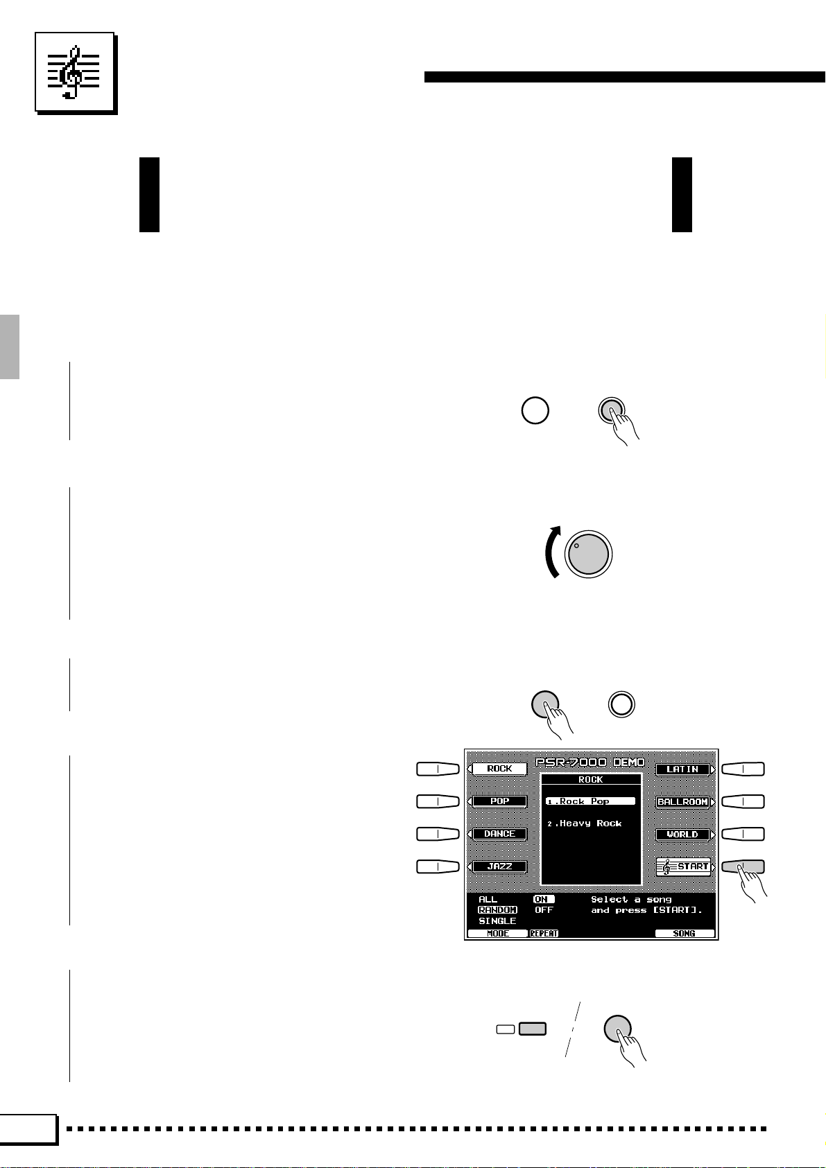
C Press the [DEMO] Button...................................................................................................................................................
Press the [DEMO] button and the PSR-7000
demo display will appear.
V Start & Stop Playback as Required
Press the START LCD button to start playback of
all demo songs. Press the STOP LCD button when
you want to stop playback.
B Exit When Done..........................................................................................................
Press either the [DEMO] button or the [EXIT]
button to exit from the demo mode and return to the
normal play-mode display when you’ve finished
playing the demo songs.
8
Page 13
The Demonstration
DEMO
EXIT
The Random & Single Demo Play Modes
If you play the demo as described above, you’ll hear all 14 demo songs played in random order. By selecting
an appropriate play mode you can also play back all the songs sequence, or play a single specified song.
Z
Select a Play Mode....................................................................................................................................................................
Use either of the LCD dials under MODE on the
display to select one of the available play modes.
ALL All 14 demo songs are played
back in sequence.
RANDOM All 14 demo songs are played back
in random order. This is the default
mode.
SINGLE SONG Only the selected song is played.
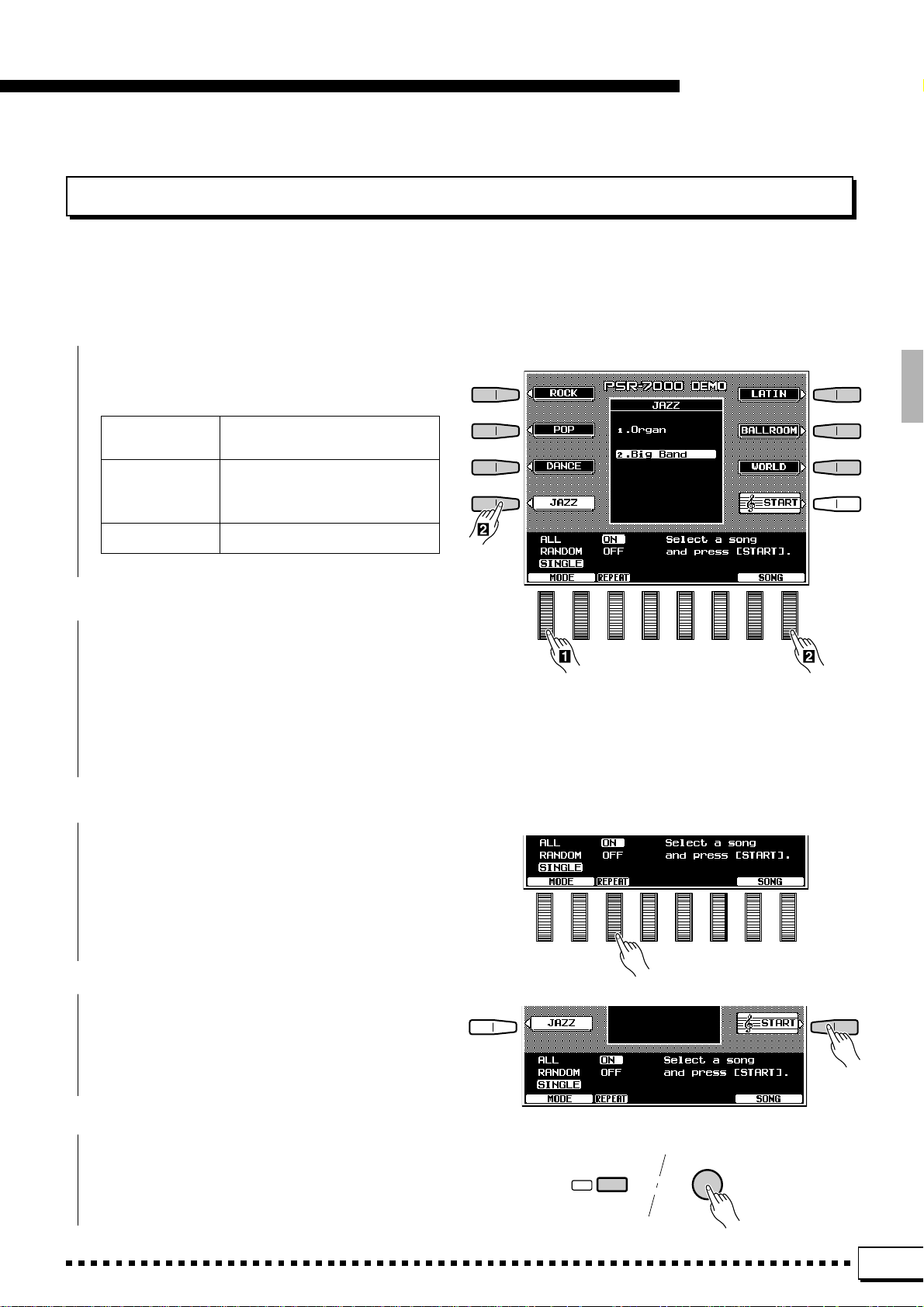
X Select a Song .........................................................
Press the LCD button corresponding to the type
of demo song you want to play, then use the same
LCD button to select either of the two demo songs in
that group. You can also use either of the LCD dials
under SONG on the display to select any of the 14
demo songs.
C Turn the Repeat Mode ON or OFF.............................................................................................................................
Use the REPEAT LCD dial to turn repeat playback ON or OFF as required (when ON, the selected
song or sequence of songs will be repeated until the
STOP LCD button is pressed)
V Start & Stop Playback as Required.........................................................................................................................
Press the START LCD button to start playback of
the selected demo song(s). Press the STOP LCD
button when you want to stop playback.
B Exit When Done ............................................................................................................................................................................
Press either the [DEMO] button or the [EXIT]
button to exit from the demo mode and return to the
normal play-mode display when you’ve finished
playing the demo songs.
9
Page 14
The PSR-7000 Display & Display-based Controls
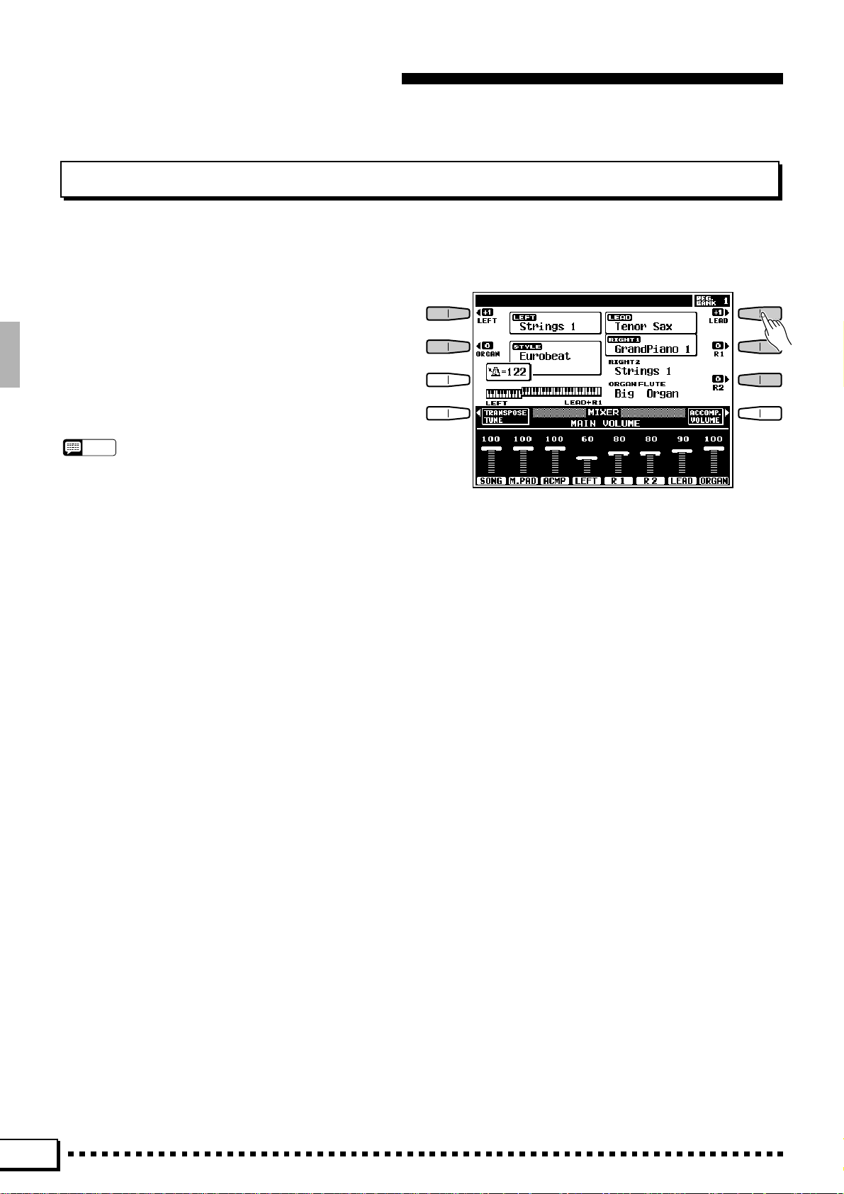
The Display & Multi-function Controls
The PSR-7000 makes general operation and programming easier than ever with a large backlit LCD display
panel and multi-function controls. The 8 LCD selectors
— four on either side of the display panel — and 8 LCD
dials below the display perform the function indicated by
the adjacent section of the display. In the example display
shown here, for example, the LCD dial immediately
below LEAD on the display can be used to adjust the
volume of the LEAD voice. Rotate the dial upward to
increase the volume, or rotate the dial downward to
decrease the volume. In the same way, the LCD button
immediately to the right of LEAD on the display is used
to set the normal octave for the lead voice (“0”), shift it
one octave up (“+1”), or one octave down (“–1”).
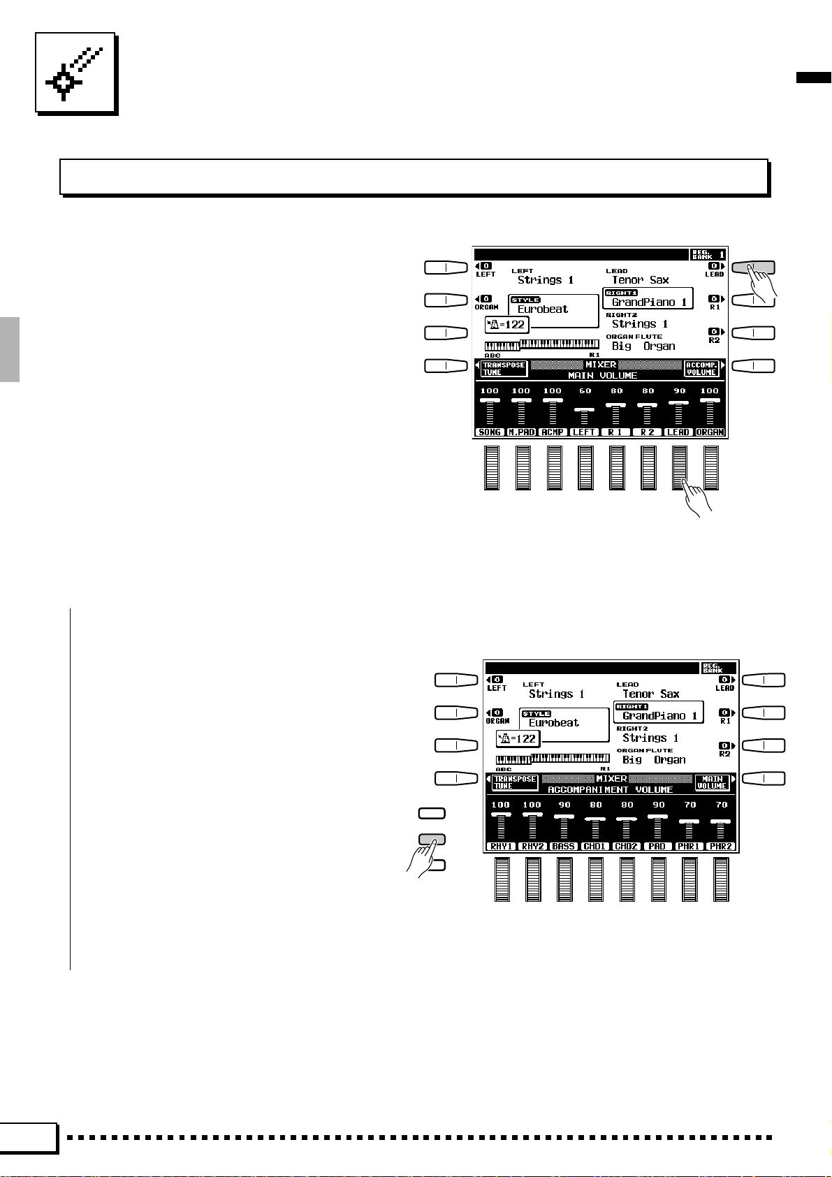
■ The [MIXER] Button..................................................................................................................................................................
The lower section of the normal play mode
display, shown above, provides individual volume
controls for the PSR-7000’s song, multi pad, accompaniment, left, right 1, right 2, lead, and organ
sound. Pressing the ACCOMP. VOLUME LCD
button switches to the individual auto-accompaniment part volume controls: rhythm 1, rhythm 2,
bass, chord 1, chord 2, pad, phrase 1, and phrase 2.
This is essentially a “mixer” that you will use the
achieve the best overall balance for your musical
needs. The mixer controls will disappear when functions which have different displays are selected, but
can be instantly recalled without exiting from the
current display mode by pressing the [MIXER]
button. Pressing the [MIXER] button a second time
(or the [EXIT] button) causes the mixer controls to
disappear.
DIGITAL
EQUALIZER
MIXER
LIST
HOLD
10
Page 15
The PSR-7000 Display & Display-based Controls
■ The [LIST HOLD] Button......................................................................................................................................................
When selecting voices (page 14) or accompaniment styles (page 26), or using the ONE TOUCH
SETTING feature (page 35), the voice, style, or
ONE TOUCH SETTING list will appear on the
display , but will automatically disappear after a few
seconds if no selections are made. The list can be
kept on the display for as long as required by
pressing the [LIST HOLD] button so that its LED
lights. Press [LIST HOLD] a second time (the LED
will go out) to disengage the list hold function.
NOTES
• If the [LIST HOLD] button is engaged when a list is not
showing, the list will not appear even when a voice group,
style group, or ONE TOUCH SETTING button is pressed.
DIGITAL
EQUALIZER
MIXER
LIST
HOLD
The [LCD CONTRAST] Control.....................................................................................................................................
■
The PSR-7000 display panel is a liquid-crystal
LCD
type which features a [LCD CONTRAST] control.
CONTRAST
Use the [LCD CONTRAST] control to set the
display for optimum legibility.
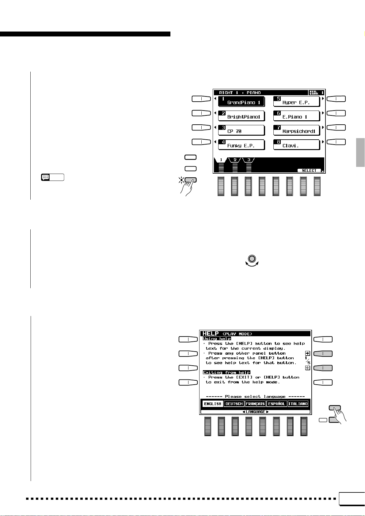
■ The 5-language Help Function .....................................................................................................................................
T o make operation as smooth and easy as possible, the PSR-7000 provides “on-line help” for most
features and functions.
Press the [HELP/LANGUAGE] button to see
help text for the current display, or press any other
panel button after pressing the [HELP/LANGUAGE]
button to see help text for that button. Press the
[EXIT] or [HELP/LANGUAGE] button when you’re
ready to exit from the help mode. If more than one
page of help text is available for the selected topic,
use the LCD buttons to the right of the display to
switch pages as necessary.
Help text and screen messages are available in
five languages: English, German, French, Spanish,
and Italian. Use the LCD dials in the help display to
select the desired language.
HELP/
LANGUAGE
EXIT
11
Page 16
Playing the PSR-7000
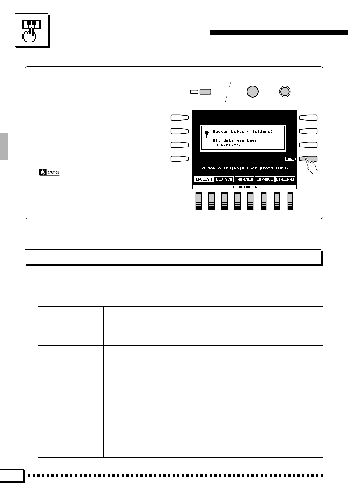
■ Before You Begin
Before playing your PSR-7000 for the first
time, it might be a good idea to re-initialize it to
the original factory settings just in case these have
been changed at some point before you receive
the instrument. To do this, turn the [POWER]
switch ON while holding the [DEMO] and [EXIT]
buttons.
When the display shown to the right appears
press the OK LCD button.
• When the above initialization procedure is carried
out, all internal data (e.g. REGISTRATION, CUSTOM STYLE, CUSTOM VOICE, MULTI PAD) will
also be initialized and therefore lost!
EXIT
DEMO
POWER
Selecting & Playing Voices
The PSR-7000 allows you to individually select and play up to four “orchestra parts” at the same time in a number
of ways. A range of voices can be assigned to each orchestra part. There’s also an “ORGAN FLUTE” part which
simulates an extremely wide range of organ sounds — complete with realistic rotary speaker effect.
RIGHT ORCHESTRA 1
RIGHT ORCHESTRA 2
LEAD This is a monophonic voice which can be played over the entire keyboard or to the right of
LEFT ORCHESTRA A polyphonic voice which can be played to the left of a specified split point while the
ORGAN FLUTE This is a polyphonic voice which can be played over the entire keyboard or to the right of a
Both the RIGHT 1 and RIGHT 2 voices are polyphonic voices which can be played over
the entire keyboard or to the right of a specified split point. The default split point is the F#2
key. Either voice can be played alone, or both can be played simultaneously. The RIGHT 1
and RIGHT 2 voices can be selected from a range of 246+8 (Drum kit) voices organized in
12 groups.
a specified split point. The default split point is the F#2 key. The LEAD voice can be played
alone, or simultaneously with either or both of the RIGHT ORCHESTRA voices. The LEAD
voice can be selected from a range of 123 voices organized in 6 groups.
When only the LEAD voice is being played it has “last note priority”. That is, only the last
note played will sound. When the LEAD voice is being played with a RIGHT ORCHESTRA
voice it has “highest note priority” — the highest note is played by the LEAD voice.
RIGHT 1, RIGHT 2, and/or LEAD voices are played to the right of the split point. The default split point is the F#2 key. The LEFT voice can be selected from a range of 205 voices
organized in 6 groups.
specified split point. The default split point is the F#2 key. The ORGAN FLUTE voice cannot be played simultaneously with the RIGHT or LEAD voices. Details on using the ORGAN FLUTE voices are provided on page 16.
* Voice numbers include Custom Voice.
12
Page 17
Playing the PSR-7000
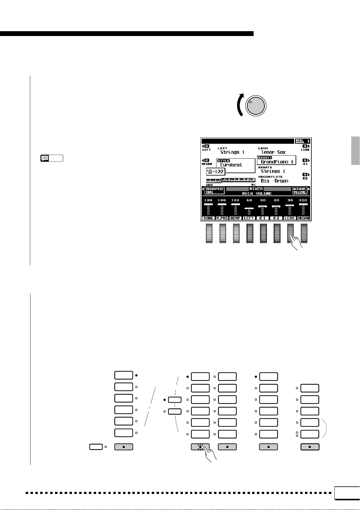
Z Set Initial Volume Levels .....................................................................................................................................................
Set the [MASTER VOLUME] control to an
appropriate level, and make sure that the LEFT, R1,
R2, LEAD and ORGAN volume levels in the MIXER
MAIN VOLUME display are set to their maximum
“100” levels (use the corresponding LCD dials to set
these volume levels if necessary). You can set the
[MASTER VOLUME] control for the most comfortable overall volume level after beginning to play .
NOTES
• No sound will be produced if all volume levels other than
the [MASTER VOLUME] control are set to their minimum
values.
MASTER VOLUME
MIN •• MAX
X Select the Orchestra Parts You Want To Play................................................................................................
Press the [RIGHT 1], [RIGHT 2], [LEAD], and/or [LEFT] button(s), turning on the
indicators corresponding to the parts you want to play . Press the [ORGAN FLUTE] button to
play the ORGAN FLUTE voice. The RIGHT 1, RIGHT 2, and LEAD voices will automatically
be turned off when the ORGAN FLUTE voice is selected. The ORGAN FLUTE voice will
automatically be turned off when the RIGHT 1 , RIGHT 2 or LEAD voice is turned on.
Each time you turn a part on or off, the EASY SETTING LCD button for that part will appear
on the LCD for a few seconds.
LEFT ORCHESTRA
PIANO/
ORGAN
STRINGS/
CHOIR
BRASS/
WOODWIND
SYNTH/
PAD
GUITAR/
PERCUSSIVE
CUSTOM
VOICE
LEFTLEFT HOLD
PART SELECT
R 1
R 2
RIGHT ORCHESTRA
PIANO
ORGAN
STRINGS/
CHOIR
SAX/
WOODWIND
TRUMPET/
BRASS
GUITAR/
BASS
RIGHT 1
ACCORDION/
WORLD
SYNTH/
PAD
SOUND
EFFECT
PERCUSSIVE
DRUM KIT
CUSTOM
VOICE
RIGHT 2
LEAD
TRUMPET/
BRASS
SAX/
WOODWIND
STRINGS/
CHOIR
GUITAR/
BASS
SYNTH/
PERCUSSIVE
CUSTOM
VOICE
LEAD
ORGAN FLUTE
SLOW
FAST
ORGAN FLUTE
COMBI
1~6
COMBI
7~12
COMBI
13~18
ROTARY
SPEAKER
SPEED
13
Page 18
Playing the PSR-7000
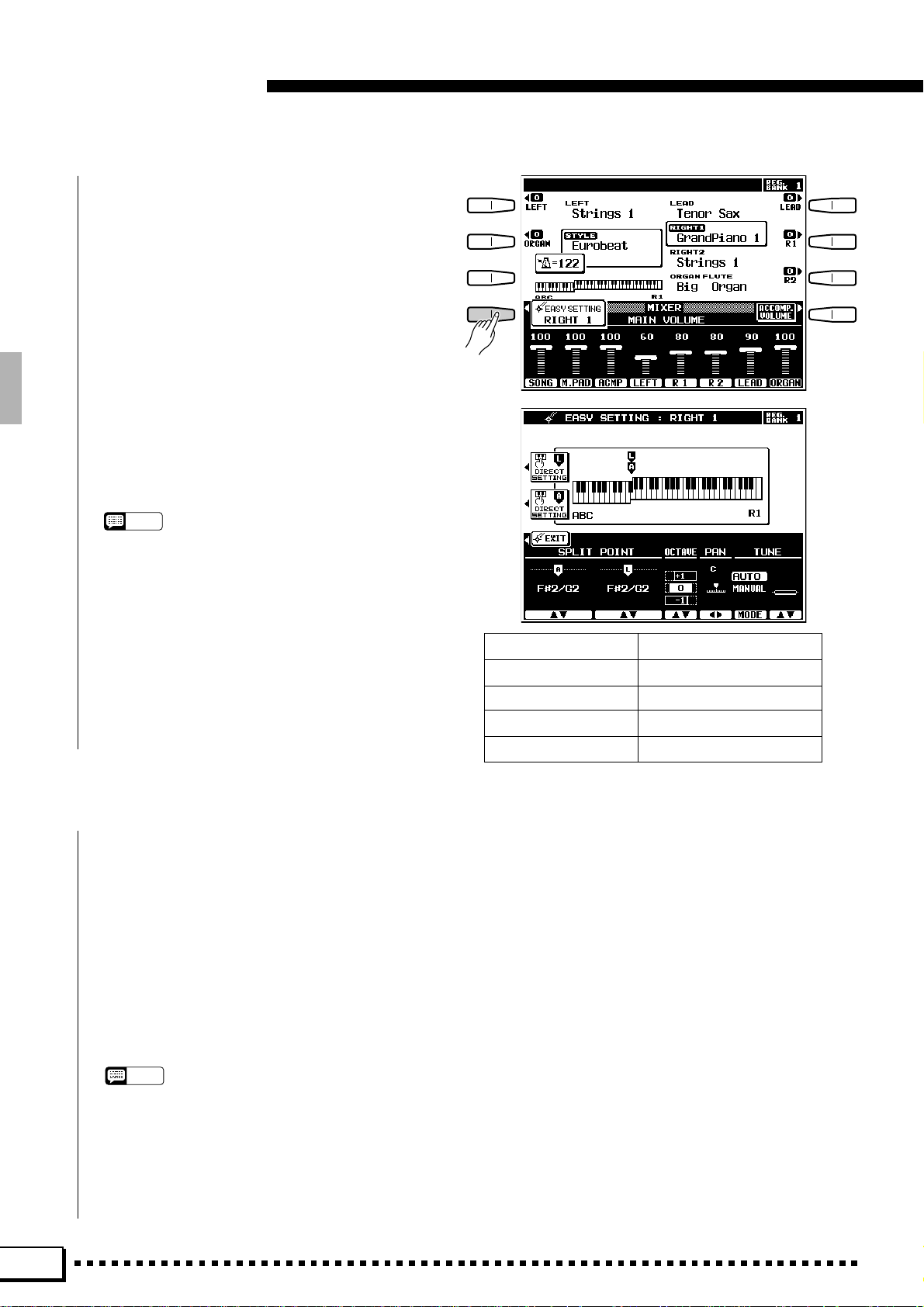
If you press the EASY SETTING LCD button
before it disappears, the easy-setting display for that
part will appear providing access to the split point
parameters as well as the individual octave, pan, and
tune parameters for that part. These same parameters can be accessed via the FUNCTION displays
(page 106), but the easy-setting displays offer an
easier, more efficient way to set these parameters
when selecting parts. The easy setting display for a
part that is already on can be accessed by pressing
the EASY SETTING LCD button while holding the
corresponding part button (in this case the part
button indicator will not go out when the button is
released). See the following pages for details on
each of the orchestra part easy setting parameters:
NOTES
• The more parts you play simultaneously, the fewer the
total number of notes that can be played on the keyboard
at the same time.
• When the RIGHT 1 and RIGHT 2 parts are both on and the
same voice is selected for both parts, the sound may be
slightly different from the normal voice.
• When the LEFT part is on, the left voice will automatically
be transposed up one octave.
SPLIT POINT [L] Page 20
SPLIT POINT [A] Page 31
OCTAVE Page 109
PAN Page 109
TUNE Page 109
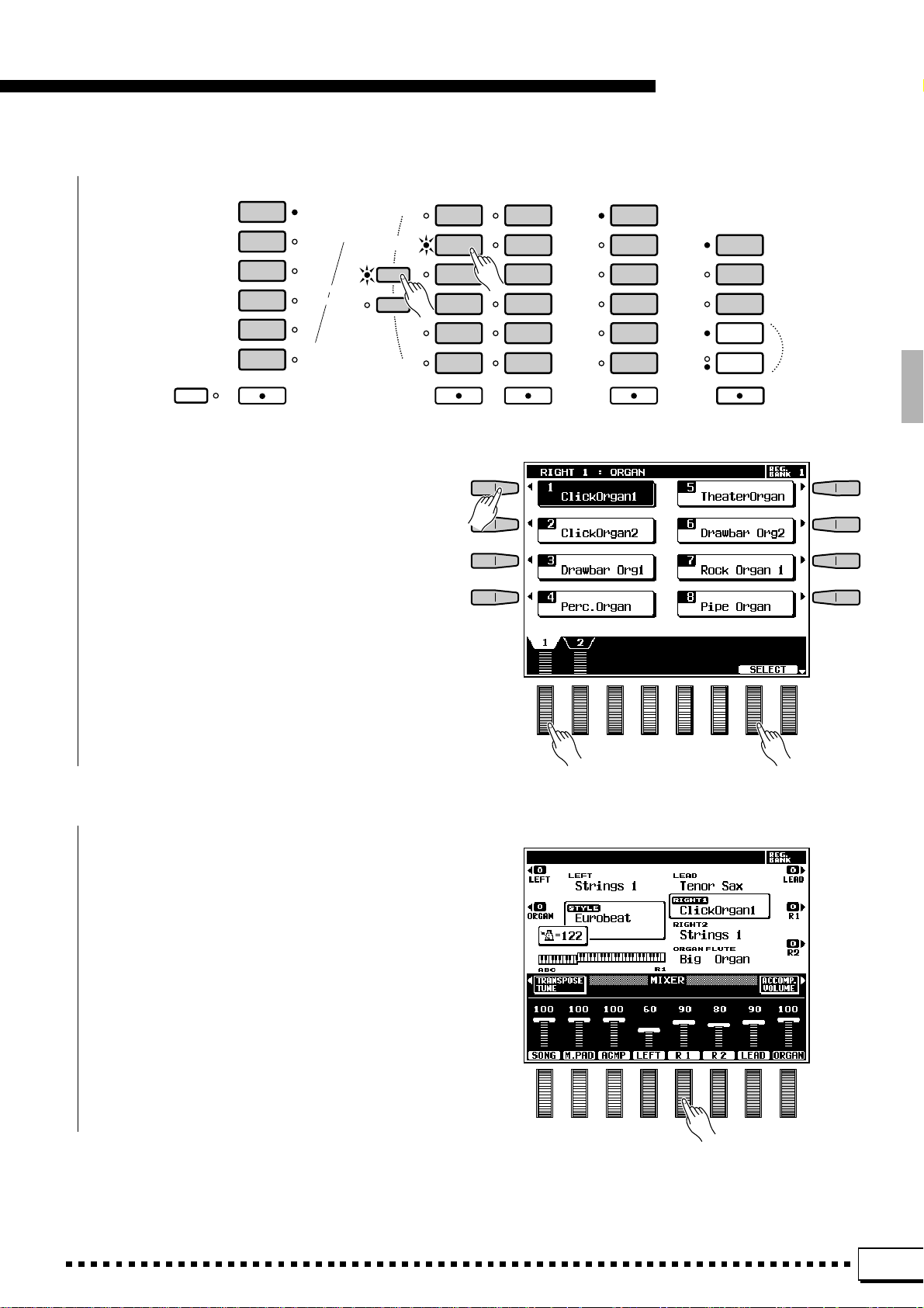
C Select a Voice or Voices........................................................................................................................................................
T o select a RIGHT 1 or RIGHT 2 voice use the RIGHT ORCHESTRA voice selectors, to select a LEAD
voice use the LEAD voice selectors, to select an ORGAN FLUTE voice use the ORGAN FLUTE voice
selectors ([COMBI 1-6], [COMBI 7-12], or [COMBI 13-18]), and to select a LEFT voice use the LEFT
ORCHESTRA voice selectors.
When selecting a RIGHT 1 or RIGHT 2 voice it is also necessary to press the [R1] or [R2] P AR T SELECT
button prior to actually selecting the voice, according to whether you want to select a RIGHT 1 or RIGHT
2 voice (this is not necessary if the [R1] or [R2] indicator for the part you want to select is already lit).
Use the voice group buttons to select the group from which you want to select a voice. The corresponding
voice display will appear.
NOTES
• The display will automatically revert to the main display
after a few seconds if the [LIST HOLD] button is not
engaged (page 11).
• Custom voices which can be selected via the RIGHT
ORCHESTRA, LEFT ORCHESTRA, and LEAD [CUSTOM] buttons can be created via the CUSTOM VOICE
EDIT mode described on page 84, or loaded from disk.
14
Page 19
Playing the PSR-7000
LEFT ORCHESTRA
PIANO/
ORGAN
STRINGS/
CHOIR
BRASS/
WOODWIND
SYNTH/
PAD
GUITAR/
PERCUSSIVE
CUSTOM
VOICE
LEFTLEFT HOLD
PART SELECT
R 1
R 2
Use the page-number LCD dials the select the
page containing the voice you want if more than one
page is available, then press the LCD button corresponding to the desired voice. You can also use
either of the SELECT LCD dials to select any of the
voices within the selected group.
RIGHT ORCHESTRA
PIANO
ORGAN
STRINGS/
CHOIR
SAX/
WOODWIND
TRUMPET/
BRASS
GUITAR/
BASS
RIGHT 1
ACCORDION/
WORLD
SYNTH/
PAD
SOUND
EFFECT
PERCUSSIVE
DRUM KIT
CUSTOM
VOICE
RIGHT 2
LEAD
TRUMPET/
BRASS
SAX/
WOODWIND
STRINGS/
CHOIR
GUITAR/
BASS
SYNTH/
PERCUSSIVE
CUSTOM
VOICE
LEAD
ORGAN FLUTE
SLOW
FAST
ORGAN FLUTE
COMBI
1~6
COMBI
7~12
COMBI
13~18
ROTARY
SPEAKER
SPEED
V Play & Adjust Volume..............................................................................................................................................................
Y ou can now play the selected voice or voices on
the keyboard. Use the [MASTER VOLUME] control to adjust the overall volume level, and the
MIXER MAIN VOLUME LCD dials to set the
desired balance between the parts.
15
Page 20
Playing the PSR-7000
Using the Organ Flute Voices
The PSR-7000 has 18 preset ORGAN FLUTE voices
which can be selected in the same way as the RIGHT,
LEAD and LEFT voices: press an ORGAN FLUTE voice
group button — [COMBI 1-6], [COMBI 7-12], or [COMBI
13-18] — and then press the LCD button corresponding
to the desired voice in the selected group. The main
difference between the ORGAN FLUTE voices and others is that the ORGAN FLUTE voices can be directly
edited via the voice list display. The editing controls
appear below the voice list (turn [LIST HOLD] on to
keep the voice list and editing controls on the display).
ORGAN FLUTE
SLOW
FAST
ORGAN FLUTE
COMBI
1~6
COMBI
7~12
COMBI
13~18
ROTARY
SPEAKER
SPEED
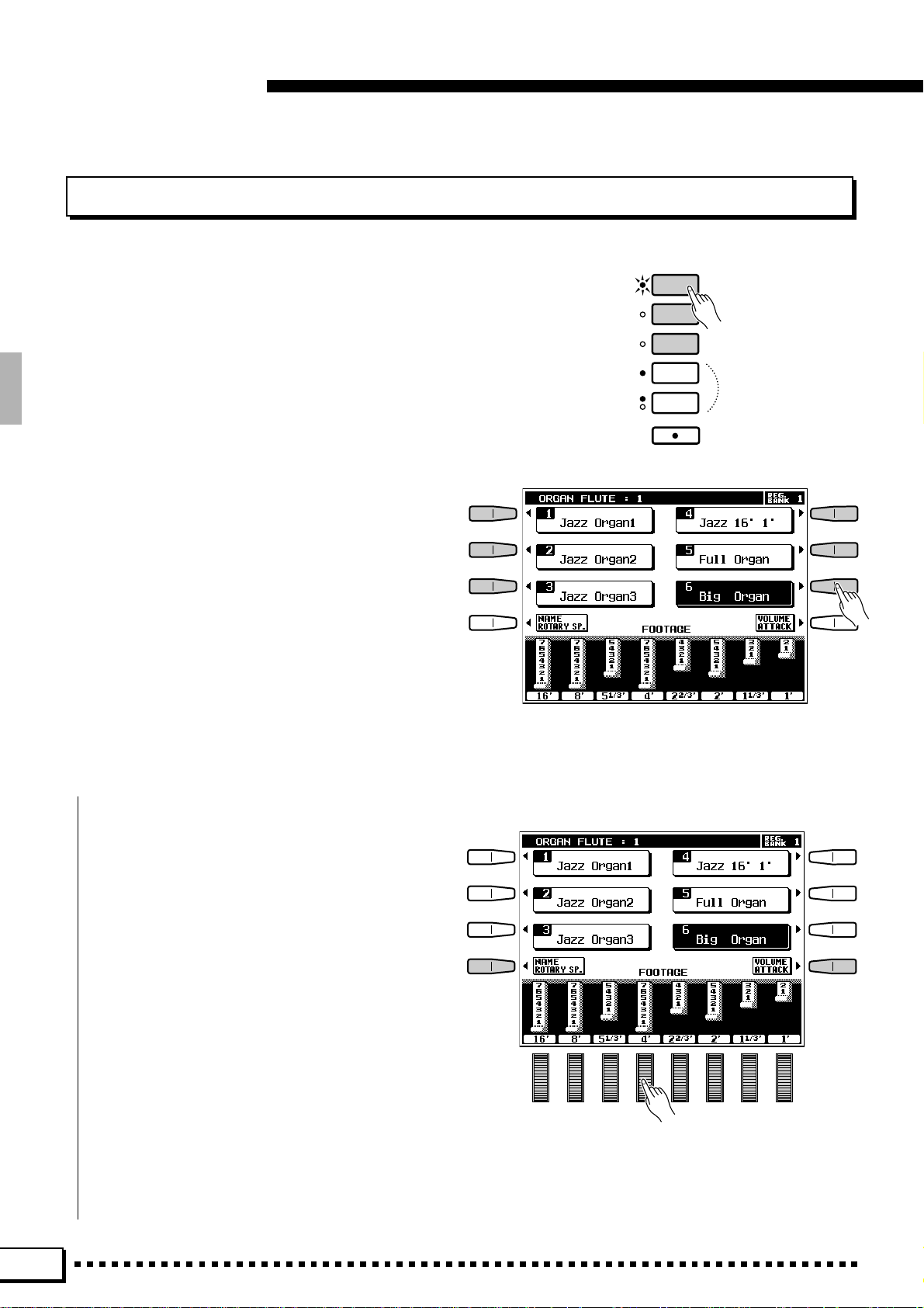
■ FOOTAGE.............................................................................................................................................................................................
The basic sound of the currently selected ORGAN FLUTE voice is edited via FOOTAGE bars
corresponding to the LCD dials. If the FOOTAGE
display is not showing, press the FOOTAGE LCD
button in the ORGAN FLUTE voice list display.
The term “FOOT AGE” is a reference to the fact that
the sound of pipe organs was adjusted via “stops”
which turned on or off pipes of different lengths (in
feet). The longer the pipe, the lower the pitch of the
sound, thus the 16' (16-foot) FOOT AGE bar adjusts
the volume of the lowest pitched component of the
voice while the 1' bar adjusts the highest-pitched
component of the voice. Use the LCD dials to
increase or reduce the amount of the corresponding
footages to create the desired overall sound. The
longer a graphic footage bar, the greater the amount
of the corresponding footage added to the sound.
16
Page 21
Playing the PSR-7000
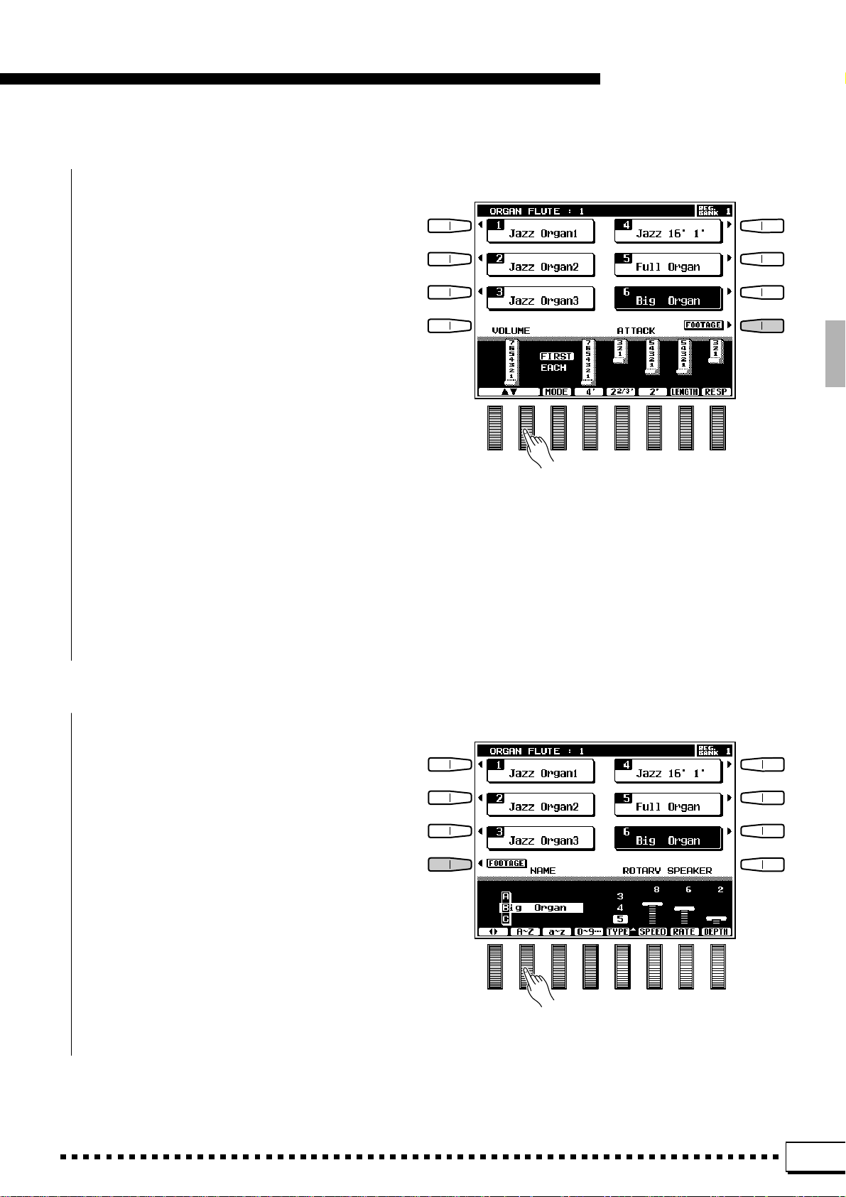
■ VOLUME & ATTACK..................................................................................................................................................................
To access the VOLUME and ATTACK parameters for the ORGAN FLUTE voices, press the
VOLUME/ATTACK LCD button from the FOOTAGE display.
The VOLUME control adjusts the overall volume of the current ORGAN FLUTE voice. The
longer the graphic bar, the greater the volume.
The ATTACK controls adjust the attack sound of
the current ORGAN FLUTE voice. The 4', 2
and 2' controls increase or reduce the amount of
attack sound at the corresponding footages. The
longer the graphic bar the greater the attack sound.
The LENGTH control produces a longer or shorter
decay after the initial attack. The longer the graphic
bar the longer the decay . The MODE control selects
the FIRST or EACH attack mode: in the FIRST
mode attack will only be applied to the first note in
a chord or group of notes played and held simultaneously; in the EACH mode attack will be applied
equally to all notes. The RESP control increases or
decreases the length of attack and release on voices
based on the FOOTAGE controls. The higher the
value the longer the attack and release.
2
/3'
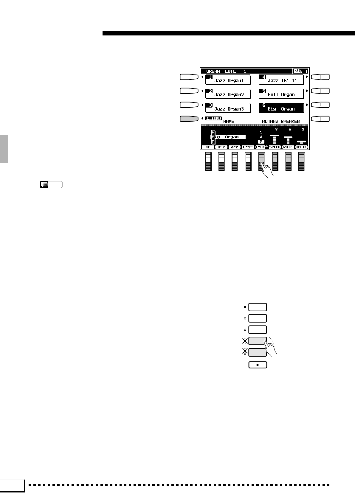
■ NAME & ROTARY SPEAKER...........................................................................................................................................
T o access the NAME and ROTARY SPEAKER
parameters for the ORGAN FLUTE voices, press
the NAME/ROTARY SP. LCD button from the
FOOTAGE display.
The NAME controls can be used to enter an
original name for the current ORGAN FLUTE voice.
V oice names can be up to 12 characters long. Use the
< > LCD dials to move the name cursor to the
various character positions, then use the A~Z, a~z
or 0~9… LCD dial to select the required character
for each position. The A~Z LCD dial selects capital
letters, the a~z LCD dial selects lower-case letters,
and the 0~9… LCD dial selects numbers and
special characters.
17
Page 22
Playing the PSR-7000
The ROTARY SPEAKER controls set up the
rotary speaker effect for the current ORGAN FLUTE
voice. The TYPE control selected one of 5 different
rotary speaker types. The SPEED control sets the
speed of the rotary speaker effect when the FAST
mode is selected: the greater the value the faster the
speed. The RATE control sets the rate of variation
between the FAST and SLOW modes: the greater
the value the faster the rate of change when the
FAST or SLOW rotary speaker mode is selected.
The DEPTH control sets the depth of the rotary
speaker effect: the higher the value the more pronounced the effect.
NOTES
• All of the above parameters can be individually pro-
grammed for each ORGAN FLUTE voice. The settings
are retained in memory even when the power is turned off
as long as a good set of backup batteries is present in the
PSR-7000 (page 2).
• The ORGAN FLUTE settings can be saved to disk and
recalled when needed via the SAVE TO DISK and LOAD
FROM DISK functions described on pages 96 and 98.
• The original factory settings can be recalled via the
RECALL PRESET DATA function described on page 123.
■ Using the Rotary Speaker Effect................................................................................................................................
When the ORGAN FLUTE voice is selected,
press the [ROT AR Y SPEAKER] button so that its
indicator lights to engage the ROT ARY SPEAKER
effect. Press the [ROTARY SPEAKER] button
again to turn the effect off. The [SPEED] button
alternately switches between the slow and fast speeds.
The current speed is indicated by the SLOW and
FAST indicators next to the [SPEED] button.
ORGAN FLUTE
SLOW
FAST
ORGAN FLUTE
COMBI
1~6
COMBI
7~12
COMBI
13~18
ROTARY
SPEAKER
SPEED
18
Page 23
Keyboard Percussion
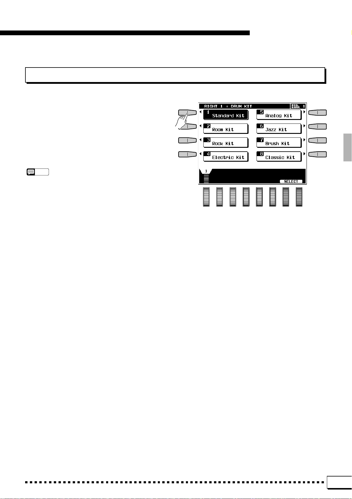
When one of the RIGHT ORCHESTRA [DRUM KIT]
voices is selected, you can play 61 different drums and
percussion instruments on the keyboard. The drums and
percussion instruments played by the various keys are
marked by symbols above the keys. Some of the instruments in the different drum kit voices sound different
even though they have the same name, while others are
essentially the same.
NOTES
• When the DRUM KIT voice OCTAVE parameter is set to “–1”, 11
different instruments are available in the lowest octave.
• The Transpose, Tune, Sustain, Harmony, Left Hold, and Modu-
lation functions do not affect the DRUM KIT voices.
• The pitch bend wheel can be used to bend the pitch of the
keyboard percussion voices to create unique musical effects,
but it has little effect on some percussion sounds.
• See page 138 for a complete listing of the keyboard percussion
drum instrument assignments.
Playing the PSR-7000
19
Page 24
Playing the PSR-7000
Changing the “L” Split Point
The PSR-7000 has two programmable split points — one which divides the LEFT and RIGHT/LEAD/ORGAN
FLUTE orchestra parts, and one which divides the auto-accompaniment and manual sections of the keyboard when
AUTO BASS CHORD accompaniment (page 31) is engaged. In the split point displays accessed by the EASY
SETTING LCD button described below , and the FUNCTION displays (page 110), the former is indicated by the “L”
marker and the latter by the “A” marker above the graphic keyboard. The current split points are indicated on the
display both by the split markers and the “splits” in the graphic keyboard. We’ll look at the ABC (“A”) split point
in more detail in “Using the Accompaniment Section”, page 31. For now, here’s how you can change the “L” split
point via the orchestra part easy-setting displays to suit your own playing requirements.
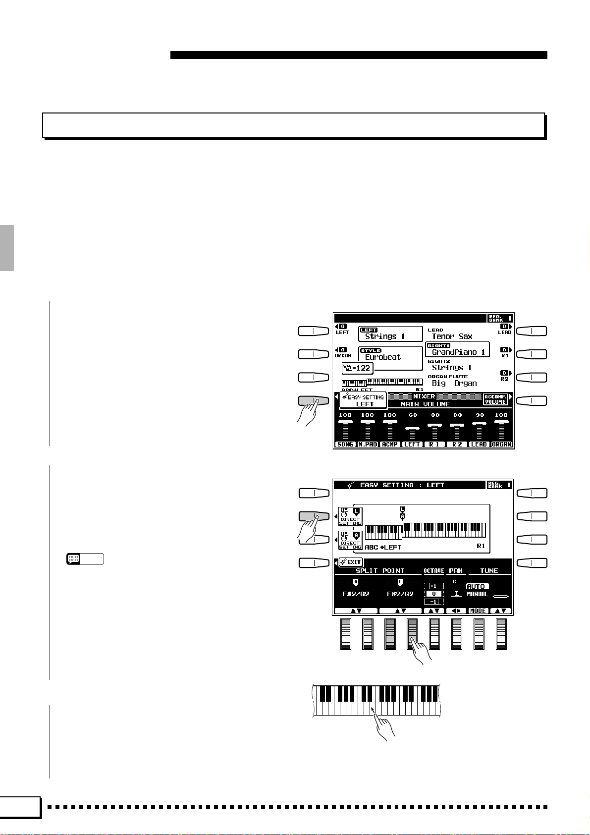
Z Select an Orchestra Part Easy Setting Display..........................................................................................
Select an orchestra part easy-setting display either by turning a part on or off and pressing the
EASY SETTING LCD button before it disappears,
or by pressing the EASY SETTING LCD button
while holding an orchestra part button that is already
on.
X Set the Split Point.......................................................................................................................................................................
The split point can be set in two ways: either use
the SPLIT POINT L LCD dials, or press the desired
key on the keyboard while holding the L DIRECT
SETTING LCD button. The new split point will be
indicated on the graphic keyboard in the LCD.
NOTES
• The “L” split point cannot be set lower than the “A” split
point.
• When the “L” and “A” split points are set at different keys,
the LEFT voice can be played between the “A” and “L” split
points when the AUTO BASS CHORD function on. When
the “L” and “A” split points are set to the same key, the
LEFT voice can be played anywhere to the left of the “L”
and “A” split points.
Press a key while holding the
C
Return to the Previous Display
When Done .......................................
Press the EXIT LCD button or [EXIT] panel
button to return to the previous display when done.
L DIRECT SETTING LCD button.
20
Page 25
Transposition, Tuning,
& Octave Change
The most important and fundamental adjustment for any musical
instrument is tuning. The TRANSPOSE, TUNING, and OCTAVE
CHANGE functions described below let you control the pitch of the
PSR-7000 in a number of ways.
TRANSPOSE & TUNE
These functions allow the overall pitch of the PSR-7000 to be transposed up or down in semitone steps, and fine-
tuned in 0.2 Hertz steps.
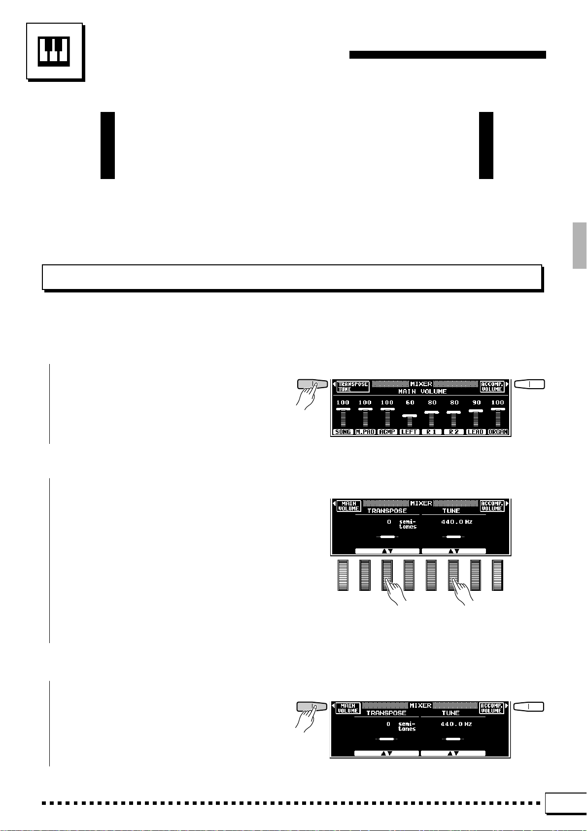
Z Press the TRANSPOSE/TUNE LCD Button .....................................................................................................
Select the transpose and tune functions from the
normal play mode display by pressing the TRANS-
POSE/TUNE LCD button.
X Set the Transposition and/or Tuning As Required...................................................................................
Use the TRANSPOSE LCD dials to set the desired degree of transposition, and the TUNE LCD
dials to set the desired degree of tuning.
The transpose range is from –24 to +24, allowing a maximum upward or downward transposition
of 2 octaves. A setting of “0” produces the normal
pitch.
The tuning range is from 414.6 Hertz to 466.8
Hertz, adjustable in 0.2-Hertz steps. A3 = 440.0
Hertz is “normal” pitch.
C Return to the Main Display When Done..............................................................................................................
Press the MAIN VOLUME LCD button to exit
from the transpose and tune functions and return to
the main display.
21
Page 26
Transposition, Tuning, & Octave Change
OCTAVE CHANGE
This function allows the LEFT, RIGHT 1, RIGHT2, LEAD, and ORGAN FLUTE voices to be independently
transposed up or down by one octave.
The LEFT, R1, R2, LEAD, and ORGAN LCD buttons
directly set the octave of the corresponding voice. Pressing one of these buttons changes the corresponding octave setting to “+1”, “–1”, and then “0”, in sequence.
“+1” shifts the voice up one octave “–1” shifts the voice
down one octave, and “0” sets the voice to its normal
octave.
NOTES
• These parameters are also available in the F1 VOICE PART
function display — page 109.
• Some voices may suddenly shift octaves when played at the
extreme ends of the keyboard if they are set to a lower or higher
octave than normal. This can also occur when the PITCH BEND
wheel is used on extremely low or high notes.
• If you change the transpose, octave change, or tuning settings
while playing one or more notes on the keyboard, the new octave
change settings will take effect from the next notes played while
tune and transpose settings take effect immediately.
22
Page 27
Using the Accompaniment Section
The PSR-7000 has 120 different preset accompaniment “styles”
and up to 32 custom accompaniment styles that can be used to provide fully-orchestrated or rhythm-only accompaniment. The PSR7000’s sophisticated Auto Bass Chord accompaniment system can
provide automated bass and chord backing that is perfectly matched
to the selected accompaniment style.
Z Turn ABC ON....................................................................................................................................................................................
Press the [AUTO BASS CHORD] button so that
its indicator lights, thereby turning the ABC mode
ACCOMPANIMENT
ROCK /
ROCK’N’ROLL
JAZZ
on.
LATIN
COUNTRY&
WESTERN
MARCH/
WALTZ
BALLROOM
CUSTOM
STYLE
AUTO BASS CHORD
ONE TOUCH
SETTING
NOTES
• Rhythm-only accompaniment will be produced if you don’t
turn the [AUTO BASS CHORD] button on.
• The maximum number of notes that can be played simultaneously on the PSR-7000 keyboard is reduced when
the Auto Bass Chord feature is used.
• The PSR-7000 employs “last-note priority”, which means
that when the number of notes played on the keyboard
exceeds the total number that can be produced by the
PSR-7000 at that time, the last notes played take priority.
POP / BEAT
BALLAD
DANCE
DISCO
RHYTHM &
BLUES
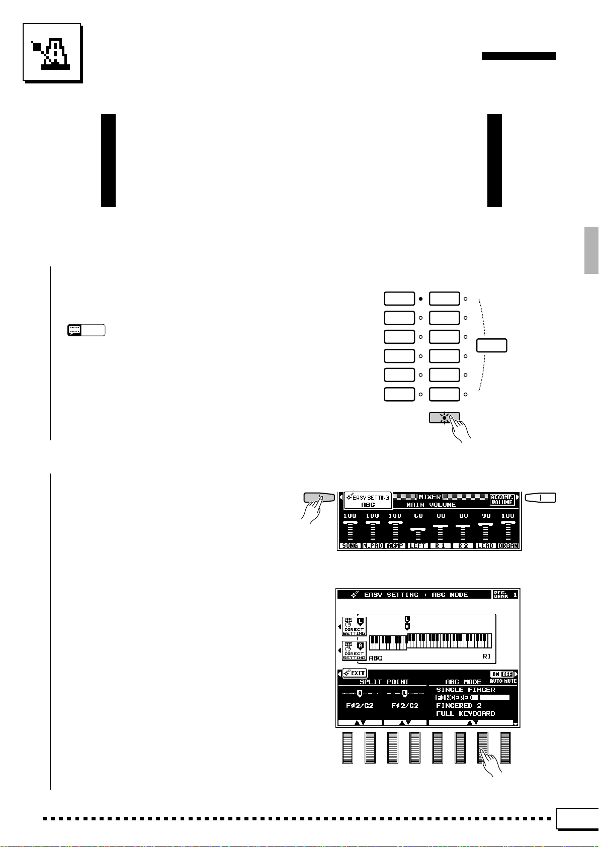
X Select the Desired ABC Mode .......................................................................................................................................
Press the ABC EASY SETTING LCD button
immediately after pressing the [AUTO BASS
CHORD] button to select the ABC MODE and
SPLIT POINT display. Use the ABC MODE LCD
dials to select the SINGLE FINGER, FINGERED 1,
FINGERED 2, FULL KEYBOARD, AUTO MIDI
BASS, or MANUAL MIDI BASS mode. If you
select the MANUAL MIDI BASS mode, and press
the BASS VOICE LCD button which appears, you
can use the GROUP LCD dials to specify the bass
voice to be used. Press the ABC MODE LCD button
to return to the ABC MODE display as required.
Press the EXIT LCD button or [EXIT] panel
button to return to the main display when done.
The SINGLE FINGER, FINGERED 1, FINGERED 2, FULL KEYBOARD, AUTO MIDI BASS
and MANUAL MIDI BASS modes function as
follows:
23
Page 28

Using the Accompaniment Section
● SINGLE FINGER (SF)
Single-finger accompaniment makes it simple to
produce beautifully orchestrated accompaniment
using major, seventh, minor and minor-seventh chords
by pressing a minimum number of keys on the lefthand section of the keyboard. The abbreviated chord
fingerings described below are used:
■ For a major chord, press the root key only.
■ For a minor chord, simultaneously press the root
key and a black key to its left.
■ For a seventh chord, simultaneously press the root
key and a white key to its left.
■ For a minor-seventh chord, simultaneously press
the root key and both a white and black key to its
left.
CGF
Cm
C
7
Cm
7
● FINGERED 1 (FC1)
This is the default ABC mode. The FINGERED
1 mode lets you finger your own chords on the ABC
section of the keyboard (i.e. all keys to the left of and
including the split-point key — normally F#2),
while the PSR-7000 supplies appropriately orchestrated rhythm, bass, and chord accompaniment in
the selected style.
The FINGERED 1 mode will accept the 34 chord
types.
● FINGERED 2 (FC2)
This mode accepts the same fingerings as the
FINGERED 1 mode, but the lowest note played in
the ABC section of the keyboard is used as the bass
root, allowing you to play “on bass” or “fraction”
chords (in the FINGERED 1 mode the root of the
chord is always used as the bass root).
24
Page 29

● FULL KEYBOARD
When this advanced auto-accompaniment mode
is engaged the PSR-7000 will automatically create
appropriate accompaniment while you play just
about anything, anywhere on the keyboard: chords,
a bass line, arpeggiated chords, a melody line. The
name of the detected chord will appear on the
display. You don’t have to worry about specifying
the accompaniment chords. Although the FULL
KEYBOARD mode is designed to work with many
songs, some arrangements may not be suitable for
use with this feature. Try playing a few simple songs
in the FULL KEYBOARD mode to get a feel for its
capabilities.
NOTES
• Chord detection occurs at approximately 8th-note inter-
vals. Extremely short chords — less than an 8th note in
length — may therefore not be detected.
Using the Accompaniment Section
● AUTO MIDI BASS
In this mode all accompaniment parts except the
bass part respond to the chord played on the keyboard. Fingering is the same as in the FINGERED 1
mode. If more than three notes are played on the
ABC section of the keyboard in this mode, and if the
chord played is not recognized by the PSR-7000,
only the top three are used for chord recognition. All
others are ignored. The bass part is determined by
the note played on an external MIDI bass keyboard
connected to the MIDI IN terminal and assigned to
the MIDI Bass channel (page 128).
● MANUAL MIDI BASS
In this no chord recognition occurs. All accompaniment parts other than the rhythm part are muted,
and a MIDI bass keyboard connected to the MIDI IN
connector and assigned to the MIDI Bass channel
(page 128) directly plays the bass voice selected via
the BASS VOICE parameter that appears when the
MANUAL MIDI BASS mode is selected in the ABC
easy-setting display.
25
Page 30

Using the Accompaniment Section
C Select a Style ...................................................................................................................................................................................
The PSR-7000 has 120 preset styles organized in
11 groups (see the “Style List” on page 130).
Use the ACCOMPANIMENT group buttons to
select the group from which you want to select a
style. The corresponding style display will appear.
NOTES
• The display will automatically revert to the main display
after a few seconds if the [LIST HOLD] button is not
engaged (page 11).
• For easy selection some styles are repeated in different
groups.
• Custom styles which can be selected via the ACCOMPA-
NIMENT [CUSTOM] button can be created via the CUSTOM ACCOMPANIMENT RECORD mode described on
page 75, or loaded from disk.
Use the page-number LCD dials to select the
page containing the style you want if more than one
page is available, then press the LCD button corresponding to the desired style. Y ou can also use either
of the SELECT LCD dials to select any of the styles
within the selected group.
The PSR-7000 automatically determines the voices
to be used for the accompaniment bass and chords
according the accompaniment style you select.
ACCOMPANIMENT
ROCK /
ROCK’N’ROLL
POP / BEAT
BALLAD
DANCE
DISCO
RHYTHM &
BLUES
JAZZ
LATIN
COUNTRY&
WESTERN
MARCH/
WALTZ
BALLROOM
CUSTOM
STYLE
AUTO BASS CHORD
ONE TOUCH
SETTING
NOTES
• Also see “Custom Accompaniment” on page 75.
• The custom style button can be used to access the styles
on optional SFF (Style File Format) disks.
V Set the Tempo .................................................................................................................................................................................
When you select a different style while the accompaniment is not playing, the “default” tempo for
that style is also selected, and the tempo is displayed
on the display in quarter-note beats per minute. If
the accompaniment is playing, the same tempo is
maintained even if you select a different style.
You can change the tempo to any value between
32 and 280 beats per minute, however, by using the
TEMPO [–] and [+] buttons. This can be done either
before the accompaniment is started or while it is
playing. T o use the [–] and [+] buttons, press either
button briefly to decrement or increment the tempo
value by one, or hold the button for continuous
decrementing or incrementing.
NOTES
• The default tempo for the selected style can be recalled at
any time by pressing both the TEMPO [–] and [+] buttons
simultaneously.
Tempo
TEMPO
–
+
26
Page 31

Using the Accompaniment Section
TEMPO TEMPO
B Start the Accompaniment..................................................................................................................................................
There are several ways to start the accompaniment:
● Straight start: Press the [START/STOP] but-
ton. If you press the [START/STOP] button, the
rhythm will begin playing immediately without
bass and chord accompaniment.
NOTES
• It is also possible to select one of the several variations
available prior to a straight start — refer to “7. Select
Variations as Required,” below.
● Start with an introduction followed b y the
MAIN A variation: press the [INTRO A/FILL
to A] button.
● Start with an introduction followed b y the
MAIN B variation: press the [INTRO B/FILL
to B] button.
● Synchronized start: Any of the above start
types can be synchronized to the first note or
chord played on the ABC section of the keyboard
(i.e. keys to the left of and including the split-
point key — normally F#2) by first pressing the
[SYNCHRO START] button. Pressing the
[SYNCHRO START] button alone causes a
straight start to occur when the first note or chord
is played. Press [SYNCHRO START] and the
appropriate INTRO button (or vice-versa) for a
synchronized introduction start. The first dot of
the TEMPO display will flash at the current
tempo when a synchronized start mode has been
selected.
FADE
IN / OUT
FADE
IN / OUT
FADE
IN / OUT
FADE
IN / OUT
INTRO/
FILL to
ABAB
ACCOMPANIMENT DIRECTOR
INTRO/
FILL to
ABAB
ACCOMPANIMENT DIRECTOR
INTRO/
FILL to
ABAB
ACCOMPANIMENT DIRECTOR
INTRO/
FILL to
ABAB
ACCOMPANIMENT DIRECTOR
MAIN
MAIN
MAIN
MAIN
ENDING/
ENDING/
ENDING/
ENDING/
rit.
rit.
rit.
rit.
SYNCHRO
START
SYNCHRO
START
SYNCHRO
START
SYNCHRO
START
START/STOP
START/STOP
START/STOP
START/STOP
NOTES
• If you press the [SYNCHRO START] button while the
accompaniment is playing, the accompaniment will stop
and the synchro start mode will be engaged.
• The four LED dots of the TEMPO display provide a visual
indication of the selected tempo as shown to the left.
• A Yamaha FC5 footswitch plugged into a rear panel
FOOT SWITCH jack can also be used to start the accompaniment if the appropriate function is assigned to the
footswitch using the FOOT SWITCH functions described
on page 112.
3/4 Time4/4 Time
1st Beat
2nd Beat
3rd Beat
4th Beat
27
Page 32

Using the Accompaniment Section
N Play On the ABC Section Of the Keyboard.....................................................................................................
As soon as you play any chord that the PSR-7000
can “recognize” on the ABC section of the keyboard
in one of the FINGERED modes or the AUT O MIDI
BASS (see fingering chart on page 144), an abbreviated chord in the SINGLE FINGER mode, or just
about anything anywhere on the keyboard in the
FULL KEYBOARD mode, the PSR-7000 will automatically begin to play the chord along with the
selected rhythm and an appropriate bass line. The
accompaniment will continue playing even if you
release the left-hand keys.
If the MANUAL MIDI BASS mode is selected
only the rhythm accompaniment will play automatically, and selected bass voice can be played via a
MIDI bass keyboard.
NOTES
• The appropriate chord and bass note will sound if you play
in the ABC section of the keyboard while the ABC function
is on but the accompaniment is stopped (but not in the
FULL KEYBOARD and MANUAL MIDI BASS modes).
Please note that the Left Hold function (page 39) cannot
be applied to these chord and bass notes.
ABC Section
Split Point
▼
3
C
Melody Section
M Select Sections as Required...........................................................................................................................................
Each accompaniment style has two sections:
MAIN A and MAIN B. There is also an ENDING
section which is described in step >. The INTRO A
and B sections can be used to start the accompaniment as described in the preceding step. The MAIN
A and B sections can be selected manually by
pressing the corresponding section button.
NOTES
• Some INTRO and ENDING sections have their own chord
progressions which play in the current accompaniment
key — the current chord is shown below the style name in
the LCD display.
FADE
IN / OUT
INTRO/
FILL to
ABAB
ACCOMPANIMENT DIRECTOR
MAIN
ENDING/
SYNCHRO
START
rit.
START/STOP
28
Page 33

Using the Accompaniment Section
< Use Fill-ins..........................................................................................................................................................................................
The PSR-7000 provides two types of automatic
breaks or “fill-ins.”
● FILL to A: Press the [INTRO A/FILL to A]
button to produce a fill and go (or return) to the
MAIN A section.
● FILL to B: Press the [INTRO B/FILL to B]
button to produce a fill and then go (or return) to
the MAIN B section.
It is possible to change the section that will play
after the fill-in by pressing the appropriate section
button while the fill-in is playing.
NOTES
• A Yamaha FC5 footswitch plugged into a rear panel
FOOT SWITCH jack can also be used to activate the intro
and fill-in functions if the appropriate function is assigned
to the footswitch using the FOOT SWITCH functions
described on page 112.
FADE
IN / OUT
FADE
IN / OUT
INTRO/
FILL to
ABAB
ACCOMPANIMENT DIRECTOR
INTRO/
FILL to
ABAB
ACCOMPANIMENT DIRECTOR
MAIN
MAIN
ENDING/
ENDING/
SYNCHRO
START
SYNCHRO
START
START/STOP
START/STOP
rit.
rit.
> Stop the Accompaniment...................................................................................................................................................
The accompaniment can be stopped at any time
by pressing the [START/STOP] button. Press the
[ENDING/rit.] button if you want to go to the
ending section and then stop. Press the [ENDING/
rit.] button while the ending section is playing to
produce a “ritardando” ending — i.e. the tempo
gradually slows down during the ending.
FADE
IN / OUT
INTRO/
FILL to
ABAB
ACCOMPANIMENT DIRECTOR
MAIN
ENDING/
SYNCHRO
START
rit.
START/STOP
29
Page 34

Using the Accompaniment Section
■ Fade-ins and Fade-outs.......................................................................................................................................................
The [FADE IN/OUT] button can be used to
produce smooth fade-ins and fade-outs when starting and stopping the accompaniment.
T o produce a fade-in, press the [FADE IN/OUT]
button so that its indicator lights before starting the
accompaniment. Then when the accompaniment is
started the sound will gradually fade in. The [FADE
IN/OUT] indicator will flash during the fade-in,
and then go out when full volume has been reached.
To produce a fade-out press the [FADE IN/
OUT] button while the accompaniment is playing.
The indicator will flash during the fade out, then the
accompaniment will stop when the fade-out is complete. The [FADE IN/OUT] button indicator will
remain lit after the fade-out, indicating that the fadein mode is engaged. Press the [FADE IN/OUT]
button so that its indicator goes out if you want to
disengage the fade-in mode.
FADE
IN / OUT
NOTES
• A Yamaha FC5 footswitch plugged into a rear panel FOOT
SWITCH jack can also be used to activate the fade-ins and fadeouts functions if the appropriate function is assigned to the
footswitch using the FOOT SWITCH functions described on
page 112.
INTRO/
FILL to
ABAB
ACCOMPANIMENT DIRECTOR
MAIN
ENDING/
SYNCHRO
START
rit.
START/STOP
■ Accompaniment Volume.....................................................................................................................................................
Use the various LCD dials in the MIXER AC-
COMPANIMENT VOLUME display to set the
best balance between the corresponding accompaniment parts, and the optimum volume of the accompaniment parts in relation to the orchestra part
voices.
■ The Auto Mute Function......................................................................................................................................................
When the EASY SETTING ABC display is selected, or when the F2 SPLIT POINT/ABC MODE
display is selected, the AUTO MUTE LCD button
will appear as long as the MANUAL MIDI BASS
ABC mode is not selected. When this function is
turned ON certain AUTO BASS CHORD parts will
either stop playing or play with reduced volume
whenever the right-hand keys are played — so that
the accompaniment does not “get in the way” of
what you play on the keyboard. Normal accompaniment playback resumes when no right-hand keys are
being played.
30
NOTES
• The AUTO MUTE function will not work with some styles.
Page 35

Using the Accompaniment Section
Changing the “A” Split Point
The “L” split point has already been described on page 16. The “A” split point divides the auto-accompaniment
and manual sections of the keyboard when AUTO BASS CHORD accompaniment (page 23) is engaged. Like the
“L” split point, the “A” split point can be changed as required via the ABC EASY SETTING display, or the SPLIT
POINT/ABC MODE/M. PAD function display (pages 110). The current split points are indicated on the display
both by the split markers and the “splits” in the graphic keyboard.
Z Select the ABC EASY SETTING Display............................................................................................................
Select the AUTO BASS CHORD easy-setting
display either by turning the [AUTO BASS CHORD]
button on and pressing the EASY SETTING LCD
button before it disappears, or by pressing the EASY
SETTING LCD button while holding the [AUTO
BASS CHORD] button.
X Set the Split Point.......................................................................................................................................................................
The split point can be set in two ways: either use
the SPLIT POINT A LCD dials, or press the desired
key on the keyboard while holding the A DIRECT
SETTING LCD button. The new split point will be
indicated on the graphic keyboard in the LCD.
NOTES
• The “A” split point cannot be set higher than the “L” split
point.
• When the “L” and “A” split points are set at different keys,
the LEFT voice can be played between the “A” and “L” split
points when the AUTO BASS CHORD function on. When
the “L” and “A” split points are set to the same key, the
LEFT voice can be played anywhere to the left of the “L”
and “A” split points.
C Return to the Previous Display When Done..................................................................................................
Press the EXIT LCD button or [EXIT] panel
button to return to the previous display when done.
31
Page 36

Using the Accompaniment Section
The Chord Assist Function
The Chord Assist function is essentially an electronic “chord book” that will show you appropriate fingerings for
chords you enter via the display. The fingerings are indicated by dots on the graphic keyboard in the display, and
correspond to those recognized in the ABC FINGERED 1 mode. You can also play chords on the keyboard in the
same way as in the ABC FINGERED 1 mode.
Z Select the Chord Assist Function.............................................................................................................................
Select the CHORD ASSIST display either by
turning the [AUTO BASS CHORD] button on and
pressing the CHORD ASSIST LCD button before it
disappears, or by pressing the CHORD ASSIST
LCD button while holding the [AUTO BASS
CHORD] button.
When the CHORD ASSIST function is selected
the ABC FINGERED 1 mode will automatically be
selected and the split point will be set at C#3.
X Start the Accompaniment ..................................................................................................................................................
Start the accompaniment by using any of the
methods described on page 27.
C Select the Chord Root and Type.................................................................................................................................
Use the ROOT LCD dial to select the desired
chord root.
Use the TYPE LCD dial to select the chord type.
The selected chord root and type will appear on
the graphic keyboard display, and the same chord
will appear in notation form on the musical staff
under “selected CHORD” in the upper half of the
display.
32
Page 37

Using the Accompaniment Section
V Hear the Chord...............................................................................................................................................................................
At this point you can “play” and hear the specified chord by pressing the ENTER LCD button —
i.e. the specified chord accompaniment will sound
and the chord will appear in notation form on the
musical staff under “played CHORD” in the upper
half of the display.
NOTES
• Chords which are recognizable by the PSR-7000 CHORD
ASSIST function can also be entered by playing them on
the ABC section of the keyboard. The chord will appear in
notation form on the musical staff under “played CHORD”
in the upper half of the display.
B Invert the Fingering as Necessary ...........................................................................................................................
Use the INVERSION LCD dials to shift the
fingering up or down the keyboard. Each time an
INVERSION LCD dial is pressed the next viable
fingering (inversion) appears on the graphic keyboard display and the musical staff below “se-
lected CHORD”.
N Stop the Accompaniment...................................................................................................................................................
Press the [START/STOP] button to stop the
accompaniment.
M Exit When Done ............................................................................................................................................................................
Press the EXIT LCD button or the panel [EXIT]
button to exit from the Chord Assist function.
33
Page 38

Using the Accompaniment Section
The Arranger Buttons
The ARRANGER buttons make it possible to indi-
vidually mute accompaniment parts to create the
blend and accompaniment “size” you want. When
an ARRANGER button is pressed so that its indica-
tor goes out, the corresponding accompaniment
part(s) are muted. Muted parts can be turned back on
by pressing the appropriate ARRANGER button so
that its indicator lights. The ARRANGER buttons
correspond to the following accompaniment parts:
PHRASE PHRASE 1, PHRASE 2
PAD PAD
CHORD CHORD 1, CHORD 2
BASS BASS
RHYTHM RHYTHM 1, RHYTHM 2
ARRANGER
PHRASE
PAD
CHORD
BASS
RHYTHM
34
Page 39

One Touch Setting
The PSR-7000’s 120 internal styles each have 4 different preset
“panel setups” that can be selected via the [ONE TOUCH SETTING]
buttons to create different musical textures — e.g. different voices for
the accompaniment parts.
Z Engage the One Touch Setting Feature ..............................................................................................................
The ONE TOUCH SETTING feature can be
used either while an accompaniment is playing or
prior to starting an accompaniment by simply pressing the [ONE TOUCH SETTING] button and
selecting the desired ONE TOUCH SETTING setup
by pressing the appropriate LCD button.
ACCOMPANIMENT
ROCK /
ROCK’N’ROLL
POP / BEAT
BALLAD
DANCE
DISCO
RHYTHM &
BLUES
LATIN
COUNTRY&
WESTERN
MARCH/
WALTZ
BALLROOM
CUSTOM
STYLE
AUTO BASS CHORD
JAZZ
ONE TOUCH
SETTING
35
Page 40

One Touch Setting
X Adjust The Settings If Necessary ..............................................................................................................................
Any of the parameters set by the ONE TOUCH
SETTING feature can be adjusted to create the
desired sound after a ONE TOUCH SETTING setup
has been selected.
NOTES
• See page 140 for a complete listing of the ONE TOUCH
SETTING setup parameters
• One Touch Settings can also be stored in the REGISTRA-
TION memory.
• ONE TOUCH SETTING cannot be used with accompani-
ment styles created using the Custom Accompaniment
feature described on page 75. An error message will
appear on the display if a Custom Style is selected.
■ THE TEMPO SET FUNCTION ..........................................................................................................................................
The TEMPO SET LCD dials in the ONE TOUCH
SETTING display can be used to turn the ONE
TOUCH SETTING TEMPO SET function ON or
OFF. When ON the tempo will change according to
the tempo setting included in each ONE TOUCH
SETTING setup whenever a different setup is selected. When OFF the tempo will not change when
a different setup is selected, regardless of the tempo
setting it includes.
36
Page 41

Expression & Effects
■ Harmony................................................................................................................................................................................................
Press the [HARMONY] button to turn the HARMONY
effect on or off. When HARMONY is on (indicator lit),
playing single notes or chords on the right-hand section of
the keyboard produces automatic harmony matched to the
accompaniment chords. The harmony function can be
turned on when AUT O BASS CHORD accompaniment is
off, but in this case the harmony produced will consist only
of unison and/or octave notes.
NOTES
• The type of harmony produced can be selected via the HAR-
MONY EASY SETTING display, or via the HARMONY function
display. See page 122 for details.
• The harmony is based on the ABC chords, and is added to the
highest note played except when only the LEAD voice is on, in
which case the harmony notes are added to the last note played.
• The HARMONY feature cannot be engaged when the FULL
KEYBOARD ABC mode is selected.
HARMONY
REVERB
SUSTAIN
CHORUS
TOUCH
RESPONSE
DSP
EFFECT
■ Sustain....................................................................................................................................................................................................
Press the [SUSTAIN] button to turn the sustain effect
on or off. When on (indicator lit), extra sustain is applied
to the selected voice. When sustain is applied via a footswitch,
however, the panel [SUSTAIN] button will not function.
NOTES
• Sustain can be applied to any combination of the LEFT, RIGHT 1,
RIGHT 2, LEAD, and ORGAN voices via the SUSTAIN BUTTON
parameter available via the SUSTAIN EASY SETTING display or
the CONTROLLER function display. See page 112 for details.
• The sustain effect may not produce the same effect for all voices.
HARMONY
REVERB
SUSTAIN
CHORUS
TOUCH
RESPONSE
DSP
EFFECT
37
Page 42

Expression & Effects
■ Touch Response ..........................................................................................................................................................................
The touch response function turns the PSR-7000’s
initial keyboard velocity and aftertouch response on or off.
Normally, touch response should be turned on — the
[TOUCH RESPONSE] button indicator should be lit —
to allow normal dynamic control via the keyboard. With
initial touch response the harder the keys are played, the
louder the sound. Aftertouch response allows the volume,
timbre, modulation, and pitch of some voices to be varied
according to how hard the keys are pressed after they have
been initially played. In some cases you might want to turn
touch response off (indicator off). For example, most
organs have no keyboard velocity response, so touch response can be turned off for greater realism when playing
organ type voices. T ouch response can also be turned off to
create a constant-volume sound with any voice.
Use the [TOUCH RESPONSE] button to turn touch
response on or off as required.
NOTES
• Aftertouch response may produce minimal or no effect with some
voices.
• When two or more of the “right-hand” parts are played at the same
time (RIGHT 1, RIGHT 2, LEAD), aftertouch response may result
in distorted sound with some voices.
• Touch response sensitivity, off level, and voice assignments can
be set via the TOUCH EASY SETTING display, or via the
CONTROLLER function display. See page 115 for details.
HARMONY
REVERB
SUSTAIN
CHORUS
TOUCH
RESPONSE
DSP
EFFECT
■ Reverb.....................................................................................................................................................................................................
TOUCH
RESPONSE
DSP
EFFECT
38
Press the [REVERB] button to apply the reverb effect
specified by the REVERB TYPE and DEPTH functions
described on page 118. The [REVERB] button alternately
turns the reverb effect on (indicator lit) or off (indicator
out).
NOTES
• Reverb type and depth settings are available via the REVERB
EASY SETTING display, or via the REVERB/CHORUS/DSP
EFFECT function display. See page 118 for details.
• Reverb type changes will apply to the note currently being played,
while reverb ON/OFF and depth changes will apply to the next
note played.
• Although the [REVERB] indicator will go out, the reverb effect
cannot be turned off during accompaniment or song playback.
HARMONY
REVERB
SUSTAIN
CHORUS
Page 43

Expression & Effects
■ Chorus ....................................................................................................................................................................................................
Press the [CHORUS] button to apply the chorus effect
HARMONY
SUSTAIN
TOUCH
RESPONSE
at a depth specified by the CHORUS DEPTH function
described on page 120. The [CHORUS] button alternately
turns the chorus effect on (indicator lit) or off (indicator
REVERB
CHORUS
DSP
EFFECT
out).
NOTES
• Chorus depth settings are available via the CHORUS EASY
SETTING display, or via the REVERB/CHORUS/DSP EFFECT
function display. See page 118 for details.
• Although the [CHORUS] indicator will go out, the chorus effect
cannot be turned off during accompaniment or song playback.
■ DSP Effects........................................................................................................................................................................................
TOUCH
RESPONSE
Press the [DSP EFFECT] button to apply the effect
specified by the DSP EFFECT TYPE and DEPTH functions described on page 120. The [DSP EFFECT] button
alternately turns the effect on (indicator lit) or off (indicator out).
NOTES
• When the default setting is selected, an appropriate DSP effect
will automatically be selected whenever a new voice is selected.
• DSP effect depth, type, and individual parameter settings are
available via the DSP EFFECT EASY SETTING display, or via the
REVERB/CHORUS/DSP EFFECT function display. See page
118 for details.
• Effect type changes will apply to the note currently being played,
while effect ON/OFF and depth changes will apply to the next note
played.
HARMONY
REVERB
SUSTAIN
CHORUS
DSP
EFFECT
■ Left Hold................................................................................................................................................................................................
This function causes the LEFT orchestra part voice to
be held even when the keys are released. Non-decaying
voices such as strings are held continuously , while decaytype voices such as piano decay more slowly (as if the
sustain pedal has been pressed).
LEFT ORCHESTRA
PIANO/
ORGAN
STRINGS/
CHOIR
BRASS/
WOODWIND
SYNTH/
PAD
GUIT A R/
PERCUSSIVE
CUSTOM
VOICE
LEFTLEFT HOLD
39
Page 44

Expression & Effects
■ Pitch Bend Wheel........................................................................................................................................................................
The PITCH BEND wheel to the left of the keyboard
lets you bend the pitch of notes played on the keyboard up
PITCH BEND MODULATION
UP
MAX
or down. Normal pitch is restored when the PITCH BEND
wheel is released. The maximum pitch bend range is preset
for each voice, but can be set as required for custom voices
by using the CUSTOM VOICE EDIT feature described on
page 89.
NOTES
• Pitch bend can be applied to the LEFT, RIGHT 1, RIGHT 2, LEAD,
and ORGAN voices — the PITCH BEND WHEEL parameter
described on page 114 allows the pitch bend wheel to be assigned
any of these voices, singly or in any combination.
• The pitch bend wheel may cause sudden pitch changes when
applied to notes at the upper and lower extremes of the keyboard.
DOWN MIN
■ Modulation Wheel .......................................................................................................................................................................
The MODULATION wheel to the left of the keyboard
lets you apply modulation to notes played on the keyboard
using the LEFT, RIGHT 1, RIGHT 2, LEAD, and ORGAN orchestra part voices. Rolling the MODULATION
wheel upward (away from you) increases the modulation
depth.
NOTES
• Modulation can be applied to the LEFT, RIGHT 1, RIGHT 2,
LEAD, and ORGAN voices — the MODULATION WHEEL parameter described on page 114 allows the modulation wheel to
be assigned any of these voices, singly or in any combination.
• With some voices the MODULATION wheel changes the depth
of effects or the timbre of the sound.
PITCH BEND MODULATION
UP
DOWN MIN
MAX
40
Page 45

Expression & Effects
■ Digital Equalizer ...........................................................................................................................................................................
The PSR-7000 features a digital 5-band equalizer that can be used to “shape” the overall frequency characteristics of the instrument to create a
wide range of tonal variations.
Press the [DIGITAL EQUALIZER] button to
access the equalizer controls. 5 preset equalizer
curves and one programmable “USER” curve are
provided. The various curves can be selected by
pressing the appropriate LCD button or by rotating
the SELECT dial.
DIGITAL
EQUALIZER
MIXER
LIST
HOLD
The USER curve can be programmed as required
via the corresponding LCD dials — LOW through
HIGH. Each of the 5 bands can be boosted (“+”
values) or cut (“–” values) by up to 12 dB. Any
changes are shown graphically via both the controls
and the markers in the USER curve. The USER
curve is automatically selected whenever any of the
equalizer parameters are edited.
Press the [DIGIT AL EQUALIZER] or [EXIT]
button to return to the normal play mode display.
NOTES
• Extreme digital equalizer settings may result in distorted
sound with some voices.
41
Page 46

The Multi Pads
REC/STOP
PERCUSSION
PHRASE/CHORD
The PSR-7000 features 8 “MULTI PADs” above the keyboard that can be used in
two ways:
● PHRASE/CHORD: When the PHRASE/CHORD mode is selected, the 4 pads marked “PHRASE”
and the 4 pads marked “CHORD” can be used to record and play back
short sequences of notes and chords, respectively.
● PERCUSSION: In the PERCUSSION mode the pads can be used to play 8 different drum
and percussion instruments selected from the PSR-7000’s DRUM KIT
voices and Custom Voice DRUM KIT voice.
PERCUSSION
REC/STOP
PHRASE/CHORD
PHRASE
12345678
NOTES
• MULTI PAD data can be saved to floppy disk. See page 98 for details.
PLAYING
MULTI PAD
PHRASE/CHORD
CHORD
The PHRASE/CHORD Mode
T o engage the PHRASE/CHORD mode, press the [PHRASE/
CHORD - PERCUSSION] button so that the PHRASE/CHORD
indicator lights (the PHRASE/CHORD and PERCUSSION indicators light alternately each time the button is pressed).
NOTES
• Preset data is initially recorded in pads 1 through 8.
The PHRASE Pads (pads 1 … 4)
Each PHRASE pad can record up to approximately 350 notes played using the RIGHT 1,
RIGHT 2, or LEAD voices (only one of these voices is recorded). The recorded phrases can then
be played back at any time — even while playing on the keyboard, with or without accompaniment. The PHRASE pads record the following data:
• Notes
• Key velocity (touch response)
• Voice number
• Volume
• Sustain
• Modulation
• Pitch bend
• PAN
• SOSTENUTO
• SOFT PEDAL
• Reverb depth
• Part tune
42
Page 47

The Multi Pads
Recording Phrases....................................................................................................................................................................
■
ZSelect a PHRASE Pad For Recording
Press the PHRASE pad you intend to record to
while holding the [REC/STOP] button. The REC/
STOP indicator will flash, indicating that the selected pad is ready to record.
XPlay a Phrase
Recording begins automatically as soon as you
play on the keyboard using the RIGHT 1, RIGHT 2,
or LEAD voice (see “NOTES”, below), and the
REC/STOP indicator will light continuously as long
as recording continues.
NOTES
• Only one voice can be recorded to the pads.
• If more than one voice is selected when the pad record
mode is engaged, the voice with the highest priority will be
used for recording. The RIGHT 1 voice has the highest
priority, followed by the RIGHT 2 voice, and then the
LEAD voice.
• The RIGHT 1 voice will automatically be selected if the
RIGHT 1, RIGHT 2, and LEAD voices are off or ORGAN
FLUTE is on when the pad record mode is engaged.
• When a pad is recorded all previous data in that pad will
be erased and replaced by the new data.
• The preset pad data can be reloaded via the RECALL
PRESET DATA function described on page 123.
• Recorded phrases which are to be played using the
CHORD MATCH function (page 111) should be recorded
in the key of C major 7.
• You can record phrases while AUTO BASS CHORD
accompaniment is playing or stopped. In either case the
phrase will be recorded in relation to the currently set
accompaniment tempo, so it is a good idea to record
phrases while monitoring the accompaniment to ensure
that they are reproduced at an appropriate tempo when
played back with accompaniment.
PERCUSSION
REC/STOP
PHRASE/CHORD
PHRASE
12345678
PLAYING
MULTI PAD
PHRASE/CHORD
CHORD
CStop Recording
Press the [REC/STOP] button to stop recording
when you’ve finished playing the phrase. The [REC/
STOP] button indicator will go out when recording
ends.
NOTES
• Recording will stop automatically if the PHRASE pad
memory becomes full (approximately 350 notes per pad),
or if another pad is pressed.
PERCUSSION
REC/STOP
PHRASE/CHORD
PHRASE
12345678
PLAYING
MULTI PAD
PHRASE/CHORD
CHORD
43
Page 48

The Multi Pads
Phrase Playback ..........................................................................................................................................................................
■
As long as the PHRASE/CHORD mode is selected,
any recorded phrase can be played back simply by
pressing the corresponding PHRASE pad. The phrase
will play back whether the accompaniment is playing or
not, but will always play at the currently set tempo. The
PHRASE/CHORD PLA YING indicator will light while
the phrase plays back, and playback will end automatically as soon as the end of the phrase is reached. A
phrase can be stopped while it is playing by pressing
either the [REC/STOP] button or the corresponding
pad button. It is also possible to play back several
phrases at the same time.
If a PHRASE pad is played while AUTO BASS
CHORD accompaniment is playing and the CHORD
MATCH function for that pad is ON (see “The Repeat
& Chord Match Settings”, below), the phrase will be
automatically re-harmonized to match the accompaniment chords.
PHRASE/CHORD
PHRASE
12345678
PLAYING
MULTI PAD
REC/STOP
CHORD
PERCUSSION
PHRASE/CHORD
NOTES
• Phrase pad data can be saved to and loaded from disk (page
96), but can not be memorized by the Registration feature
(page 49).
• Use the M.PAD VOLUME control in the MIXER MAIN VOL-
UME display to adjust the playback volume of the phrase
pads.
• Only one pad can be played at a time in the SONG RECORD
mode (page 58).
The CHORD Pads (pads 5 … 8)
Each CHORD pad can record up to approximately 50 chords played on the left-hand
section of the keyboard when the AUT O BASS CHORD feature is engaged. The recorded
chords can then be played back when ABC is engaged and an accompaniment is playing.
■ Recording Chords......................................................................................................................................................................
ZSelect a CHORD Pad For Recording
Press the CHORD pad you intend to record to while
holding the [REC/STOP] button. The REC/STOP indi-
cator will flash, indicating that the selected pad is ready
to record. If the accompaniment is stopped when the
CHORD pad is selected for recording, the SYNCHRO
START mode will automatically be engaged.
NOTES
• If AUTO BASS CHORD is OFF when a CHORD pad is
selected for recording, it will automatically be turned ON.
Further, if the MANUAL MIDI BASS mode is selected, the
FINGERED 1 mode will automatically be selected.
REC/STOP
PHRASE/CHORD
PHRASE
12345678
PLAYING
MULTI PAD
CHORD
PERCUSSION
PHRASE/CHORD
44
Page 49

XPlay the Required Chords
Recording begins automatically as soon as you play a chord
on the left-hand section of the keyboard, and the REC/STOP
indicator will light continuously as long as recording continues.
The Multi Pads
CStop Recording
REC/STOP
PERCUSSION
PHRASE/CHORD
Press the [REC/STOP] button or the pad being recorded to
stop recording when you’ve finished playing the chords. The
[REC/STOP] button indicator will go out when recording ends.
NOTES
• Recording will stop automatically if the CHORD pad memory becomes
full (approximately 50 chords per pad); if another pad is pressed; or if the
accompaniment [START/STOP], or [SYNCHRO START] button is
pressed.
• Quarter note steps are the smallest that can be recorded.
345678
PHRASE/CHORD
PLAYING
MULTI PAD
CHORD
■ Chord Playback.............................................................................................................................................................................
As long as the PHRASE/CHORD mode is selected and an
AUTO BASS CHORD accompaniment is playing, any recorded
chord sequence can be played back simply by pressing the
corresponding CHORD pad. The chord sequence will play back
at the currently set tempo. The PHRASE/CHORD PLAYING
indicator will light while the chord sequence plays back, and
playback will end automatically as soon as the end of the
sequence is reached. Only one chord sequence can be played at
a time.
During chord pad playback the AUT O BASS CHORD indicator will go out and the left-hand section of the keyboard plays in
the same way as the right-hand section. To indicate that the end
of the chord sequence is approaching, the PHRASE/CHORD
PLAYING indicator flashes during the last two measures (if the
REPEAT mode is not engaged — see below). A chord sequence
that is playing can be stopped by pressing the same chord pad
again, or by pressing the [REC/STOP] button. The AUTO BASS
CHORD function will continue playing the last chord played in
the chord sequence.
REC/STOP
PHRASE/CHORD
PLAYING
345678
MULTI PAD
CHORD
PERCUSSION
PHRASE/CHORD
NOTES
• If you press a CHORD pad while the accompaniment is stopped or while
the AUTO BASS CHORD function is off, “Engage ABC to play the chord
pads” will appear on the display. Also, if AUTO BASS CHORD is on but
the MANUAL MIDI BASS mode is selected, “Engage SF, FC1, FC2,
FULL KEYBOARD, or AUTO MIDI BASS mode to play the chord pads”
will appear on the display, since chord playback will not function in the
MANUAL MIDI BASS mode.
• Chord pad data can be saved to and loaded from disk (page 96), but can
not be memorized by the Registration feature (page 49).
• Playback occurs in measure units. Playback will continue until the end of
the measure even if recording was stopped prior to the end of that
measure.
45
Page 50

The Multi Pads
The Repeat & Chord Match Settings......................................................................................................................
■
The repeat and chord match settings for PHRASE/
CHORD pad playback can be accessed by pressing
the EASY SETTING LCD button that appears when
the [PERCUSSION - PHRASE/CHORD] button
is pressed. Once the easy setting display has been
selected the repeat and chord match parameters can
be accessed by pressing the REPEAT or CHORD
MATCH LCD button.
Press either the EXIT LCD button or the panel
[EXIT] button when done.
NOTES
• The MULTI PAD repeat and chord match settings are also
available via the MULTI PAD FUNCTION display — page
111.
● REPEAT
When a check mark appears in a REPEA T box in
the REPEAT display, the corresponding pad —
PHRASE or CHORD — will playback repeatedly
until stopped by either pressing the same MULTI
P AD again, or by pressing the [REC/STOP] button.
Use the LCD dials to turn repeat for the corresponding pads ON or OFF as required.
NOTES
• The default repeat settings are: pads 1…4 OFF; pads
5…8 ON.
● CHORD MATCH
When a check mark appears in a CHORD MA TCH
box in the CHORD MATCH display, the phrase
played by the corresponding PHRASE pad will be
automatically re-harmonized to match the accompaniment chords if the PHRASE pad is played while
AUTO BASS CHORD accompaniment is playing.
46
Page 51

Use the LCD dials to turn the chord match function for
REC/STOP
PERCUSSION
PHRASE/CHORD
REC/STOP
PERCUSSION
PHRASE/CHORD
the corresponding pads ON or OFF as required.
NOTES
• Phrases to be played back using the CHORD MATCH function
must be recorded in the key of C major 7.
• The chord match function is only available for pads 1 through 4 (the
PHRASE pads).
• The default chord match settings are:1 and 2 OFF; 3 and 4 ON.
The PERCUSSION Mode
To engage the PERCUSSION mode, press the [PHRASE/CHORD PERCUSSION] button so that the PERCUSSION indicator lights (the
PHRASE/CHORD and PERCUSSION indicators light alternately each
time the button is pressed).
The 8 pads are initially programmed with the following drum and
percussion instruments which can be played via the pads when the PERCUSSION mode is selected:
The Multi Pads
1. Kick M
2. Snare M
3. C.Hi-Hat
4. O.Hi-Hat
5. MidTom H
6. Low Tom
7. F Tom L
8. CrashCy2
■ Assigning Different Instruments To the PERCUSSION Pads......................................................
ZPress [REC/STOP]
Press the [REC/STOP] button so that its indicator
lights (make sure the PERCUSSION mode is selected
first). The PERCUSSION PAD ASSIGN display will appear, listing the percussion instruments currently assigned
to the pads.
XSelect a Drum Voice
Use the DRUM KIT LCD dials to select the drum voice
which includes the percussion instruments you want to
assign.
47
Page 52

The Multi Pads
CAssign the Instruments
A new drum/percussion instrument is assigned
to a pad simply by playing the key corresponding to
the desired instrument while holding the pad to
which it is to be assigned. The reverse also works:
press the pad while holding the key . The velocity at
which you play the key (how hard you press the key
= how loud the note sounds) is also recorded to the
specified pad.
NOTES
• Percussion voices created using the CUSTOM VOICE
EDIT functions described on page 84 can also be assigned to the percussion pads.
VPress [REC/STOP] To End Assignment
When you’re finished making instrument assignments to the PERCUSSION pads, press the
[REC/STOP] button so that its indicator goes out.
NOTES
• Percussion pad data can be saved to and loaded from disk
(page 96), but can not be memorized by the Registration
feature (page 49).
PERCUSSION
CHORD
CHORD
PHRASE/CHORD
PERCUSSION
PHRASE/CHORD
REC/STOP
PHRASE/CHORD
PHRASE
12345678
PHRASE
12345678
PLAYING
MULTI PAD
PHRASE/CHORD
PLAYING
MULTI PAD
REC/STOP
■ Playing the Percussion Pads .........................................................................................................................................
The PERCUSSION pads can be played at any
time — whether an accompaniment is playing or not
— as long as the PERCUSSION mode is selected.
Depending on the assigned instrument, some pads
will play continuously as long as they are held.
NOTES
• The PERCUSSION pad sounds are not affected by the
PSR-7000 PITCH BEND wheel or MODULATION wheel.
REC/STOP
PHRASE/CHORD
PHRASE
12345678
PLAYING
MULTI PAD
CHORD
PERCUSSION
PHRASE/CHORD
48
Page 53

Registration Memory
FREEZE MEMORY
BANK 1~16
+
–
12345678
REGISTRA TION
BANK 1~16
+
–
12
The PSR-7000 Registration Memory feature can be used to memorize 128 complete control-panel setups (16 banks, 8 setups each) that
you can recall whenever needed.
NOTES
• Registration data can be saved to and loaded from floppy disk as required (page 96).
• The disk provided with the PSR-7000 contains a number of sample registration settings.
Registering the Panel Settings
Z Set Up the Controls as Required ...............................................................................................................................
Make the desired control settings.
NOTES
• See page 140 for a complete listing of the data stored by
the Registration function.
X Register in Memory...................................................................................................................................................................
Use the BANK [–] or [+] button
to select the desired memory bank
— the bank number is shown next to
REG. BANK in the upper right corner of the display . Press and hold the
[MEMORY] button, then press one
of the REGISTRATION buttons.
Any data that was previously in the
selected location is erased and replaced by the new settings.
49
Page 54

Registration Memory
Entering a Registration Name
Y ou can enter descriptive names up to 16 characters in length for each registration setup via the NAME
function accessible via the registration EASY SETTING display. The same function is also available via
the FUNCTION display — page 122.
Z Select the NAME Function ................................................................................................................................................
Press the EASY SETTING LCD button that appears when a BANK button or the [MEMORY]
button is pressed before it disappears. When the
easy setting display appears, select the NAME function by pressing the corresponding LCD button.
X Enter a Name ...................................................................................................................................................................................
Use the < > LCD dial to move the name cursor
to the various character positions, then use the A~Z,
a~z, or 0~9… LCD dial to select the required
character for each position. The A~Z LCD dial
selects capital letters, the a~z LCD dial selects
lower-case letters, and the 0~9… LCD dial selects
numbers and special characters.
NOTES
• It’s a good idea to give your registration setups names that
make them easily identifiable. If you’ve created a registration setup for a song named “MySong”, a good registration
name might be something like “MySong-Reg”.
C Exit When Done.............................................................................................................................................................................
Press either the EXIT LCD button or the panel
[EXIT] button when done.
50
Page 55

Recalling the Registered Panel Settings
FREEZE MEMORY
BANK 1~16
+
–
12345678
REGISTRA TION
Simply select the appropriate bank
using the BANK [–] or [+] button
and press the desired REGISTRA-
TION button at any time to recall
the memorized settings. The memorized settings are actually recalled
only when a REGISTRATION
button is pressed — selecting a different bank does not change the
settings.
The selected bank and registration number appears at the top of the display . The registration name
appears to the right of the bank and number.
Registration Memory
If any change is made to a setting memorized by
the REGISTRATION feature, “REGIST EDITED”
appears in place of the bank, number, and name to
indicate that the current panel settings do not exactly
correspond to the selected registration memory.
51
Page 56

Registration Memory
The Freeze Function
If you press the [FREEZE] button so that its LED lights, selecting a
different registration setup will not change the settings specified in the
FREEZE GROUP SETTING display accessed either via the registration
EASY SETTING display or the [FUNCTION] button (page 122).
FREEZE MEMORY
BANK 1~16
–
+
12
The Freeze Group Settings
Y ou can specify which settings are affected by the FREEZE function via the FREEZE GROUP SETTING
function accessible via the registration EASY SETTING display. The same function is also available via the
FUNCTION display — page 122.
Z Select the FREEZE GROUP SETTING Function ........................................................................................
Press the EASY SETTING LCD button that appears when a BANK button or the [MEMORY]
button is pressed before it disappears. When the
easy setting display appears, select the FREEZE
GROUP SETTING function by pressing the corresponding LCD button.
X Mark the Settings to be “Frozen” .....
Use the GROUP SELECT LCD dials to select a
setting you want to freeze or “un-freeze”, then use
the MARK LCD dial to set or remove the check
mark for that setting. Repeat until all settings are
marked or un-marked as required.
C Exit When Done.............................................................................................................................................................................
Press either the EXIT LCD button or the panel
[EXIT] button when done.
52
Page 57

Song Playback & Recording
SONG
PLAY
FUNCTION
SONG
RECORD
CUSTOM
ACCOMP. REC
DISK
CUSTOM
VOICE EDIT
Song Playback
The PSR-7000 SONG PLAY mode allows song data to be played back from a floppy disk or the optional hard
disk. The song file types which can be played by the PSR-7000 are: songs recorded on the PSR-7000, DOC (Disk
Orchestra Collection), PianoSoft and GM song (SMF format). Refer to the DOC or SMF disk manuals as necessary .
About the Supplied Disk
The floppy disk supplied with the PSR-7000 includes a number of sample songs with wave data that are automatically
loaded when the disk is inserted. When the data is loaded the SONG PLAY mode is automatically engaged, and you
can then select and play the various sample songs as described below. Please note that the internal wave data (custom voice data), registration data, and SETUP data will be overwritted by the data loaded from the supplied disk.
Z Insert a Song Disk......................................................................................................................................................................
Insert a song disk into the PSR-7000 disk drive
— a disk containing songs you have recorded on the
PSR-7000 yourself, a Y amaha DOC (Disk Orchestra
Collection), a Y amaha PianoSoft disk, or a GM song
disk. The SONG PLAY mode will be automatically
engaged if a DOC, PianoSoft or GM song disk is
inserted (and an accompaniment is not playing).
Otherwise engage the SONG PLAY mode as described in the following step.
X Engage the Song Play Mode...........................................................................................................................................
Press the [SONG PLAY] button to engage the
SONG PLA Y mode. The SONG PLAY display will
appear.
NOTES
• If the optional hard disk is present, DIR ▲▼ dials will be
available in the SONG PLAY display. These can be used
to select the floppy disk or the hard disk directory containing the desired song.
53
Page 58

Song Playback & Recording
C Select a Play Mode ....................................................................................................................................................................
Use the MODE LCD dials to select a play mode:
SINGLE Plays the single song selected via
the SONG SELECT controls.
ALL Plays all songs in the song list in
order.
CHAIN Plays the songs specified in the
CHAIN LIST in the specified order.
Set this via the MAKE CHAIN button.
RANDOM Plays all songs in the song list in
random order.
Also, use the REPEAT LCD dial to turn the
repeat mode ON or OFF as required. When ON,
playback will repeat continuously until stopped.
V Start/Stop Playback..................................................................................................................................................................
Press the START LCD button to start playback.
Playback will stop automatically when the specified
song(s) have been played all the way through (unless the repeat mode is ON). You can also stop
playback at any time by pressing the STOP [■] LCD
button.
NOTES
• The ORGAN FLUTE voice cannot be played on the
keyboard when playing back a track on which the
ORGAN FLUTE voice is recorded.
■ Pause, Fast Forward & Reverse..................................................................................................................................
When you press the STOP [■] LCD button,
playback stops and the song position returns to the
beginning of the song. The PAUSE LCD button,
however, lets you pause playback and then start
again from the same point in the song. Playback can
be restarted either by pressing the PAUSE LCD
button again or by pressing the START LCD button.
While the PAUSE mode is engaged the F.F.
[f] (Fast Forward) and REW [r] (Reverse) LCD
buttons rapidly move the playback location forward
and backward in 1-measure steps, respectively . The
[r] and [f] buttons can be used both during
playback and while playback is paused. The REW
[r] LCD button will not appear and reverse operation will not be possible when a GM song disk (SMF
Format 1) is being played.
The display shown appears when
the supplied disk is used.
54
Page 59

Song Playback & Recording
Chain Playback
Chain playback allows any number of songs to be grouped together in any order for playback.
To program a chain:
Z Press the MAKE CHAIN LCD Button .....................................................................................................................
The MAKE CHAIN LCD button will take you to
the chain programming display.
X Select and Insert the Required Songs .................................................................................................................
Use the SONG LCD dials to select a song, use the
CHAIN LIST LCD dials to select a position in the
chain if the chain contains more than one song, and
finally press the INS LCD button to insert the song
at the current position. Repeat this process to insert
the required songs at the required locations.
C Delete Songs As Required................................................................................................................................................
To delete a song from the chain list simply use
the CHAIN LIST LCD dials to select the song to be
deleted, then press the DEL LCD button.
55
Page 60

Song Playback & Recording
V Save the Chain List, If Necessary.............................................................................................................................
The completed chain list can be saved to disk by
pressing the LIST SAVE LCD button. A confirmation display will appear (“OK to save chain data?”):
press YES to save the list or NO to cancel.
NOTES
• Chain list data cannot be saved to a DOC or PianoSoft
disk.
B
Return to the Song Select Display...........................................................................................................................
Press the SONG SEL. LCD button to return to the
SONG SELECT display.
Volume & Mute/Solo Settings
The volume, mute, and solo parameters for song
playback are available via the VOLUME/MUTE
display which can be accessed by pressing the [
LCD button to the right of the display. Press the
VOLUME or MUTE LCD button to switch to the
corresponding display.
]
56
Page 61

Song Playback & Recording
The number of volume parameters in the TRACK
VOLUME display will depend on the type of song
being played. If an original song recorded on the
PSR-7000 using the QUICK RECORD mode is
being played, two volume parameters will be available: MANUAL and ACCOMP. If an original song
recorded on the PSR-7000 using the MUL TITRACK
RECORD mode or a GM song is being played,
individual parameters for all 16 tracks will be available: TR1 through TR16. Use the LCD dials to set
the volume of the corresponding tracks. If a Y amaha
DOC song is being played use the RHY, BASS,
ORCH, LEFT, and RIGHT LCD dials to set the
volume of the corresponding tracks (see the DOC or
PianoSoft software manual for more details). If a
PianoSoft song is being played use the ORCH,
LEFT, and RIGHT LCD dials to set the volume of the
corresponding tracks.
The LCD dials in the TRACK MUTE display
allow PLAY, MUTE, or SOLO to be selected for
each track group. Muted tracks do not play . If a track
is set to SOLO only that track will play.
The track indicators above the volume or mute/
solo parameters indicate which tracks contain data
and which are muted. Tracks which do not contain
data are indicated by a dotted circle outline while
tracks which contain data have a solid outline. Playenabled tracks are indicated by a filled circle while
tracks that are muted are indicated by an outline
only.
QUICK RECORD song
MULTITRACK RECORD song
DOC song
NOTES
• When GM song is played all tracks appear on the display
as if they contain data, even if they don’t.
GM song
57
Page 62

SONG
PLAY
FUNCTION
SONG
RECORD
CUSTOM
ACCOMP. REC
DISK
CUSTOM
VOICE EDIT
Song Playback & Recording
Song Recording
The PSR-7000 SONG RECORD mode allows anything you play to be recorded to floppy disk. A QUICK
RECORD mode provides an easy way to record a melody with accompaniment, while a MUL TITRACK record mode
allows independent recording on up to 16 tracks. There’ s also a CHORD SEQUENCE record mode available via the
QUICK record mode.
Z Insert a Recordable Disk.....................................................................................................................................................
Insert a properly formatted disk in the PSR-7000
disk drive.
X Engage the Song Record Mode...................................................................................................................................
Press the [SONG RECORD] button to engage
the SONG RECORD mode. The SONG RECORD
display will appear.
NOTES
• If an unformatted disk or a disk which has not been
formatted for use with the PSR-7000 is inserted, the
“Wrong disk format! Format disk?” confirmation message
will appear when the SONG RECORD mode is selected.
Press YES to format the disk or NO to cancel.
• If a GM disk is in the drive when the SONG RECORD
mode is engaged, the “Not a user disk! Recording to this
disk will convert it to a user disk. OK to record?” message
will appear on the display. Press YES to enter the record
mode or NO to cancel.
• If a DOC or PianoSoft disk is in the drive when the SONG
RECORD mode is engaged the “Write protected!” message will appear and it will not be possible to enter the
record mode.
▲▼
• If the optional hard disk is present, DIR
available in the SONG PLAY display. These can be used
to select the floppy disk or the hard disk directory to which
the song is to be recorded.
dials will be
58
Page 63

Song Playback & Recording
C Select a Song..................................................................................................................................................................................
Use the SONG LCD dials to select either an
existing song for additional recording or a new song
(“
” on the SONG LIST) to record a new song.
V Enter a Song Name, If Necessary .............................................................................................................................
You can enter an original name for the song at
this point. Song names can be up to 12 characters
long. Use the < > LCD dial to move the name
cursor to the various character positions, then use
the A~Z, a~z, or 0~9… LCD dial to select the
required character for each position. The A~Z LCD
dial selects capital letters, the a~z control selects
lower-case letters, and the 0~9… LCD dial selects
numbers and special characters.
B Select a Record Mode ............................................................................................................................................................
Press the QUICK RECORD or MULTI TRACK
LCD button to select the corresponding record mode.
59
Page 64

Song Playback & Recording
Quick Record
The QUICK RECORD mode, as its name suggests, makes track selection and recording easy by grouping the
accompaniment and manual tracks.
Z Set the Track Modes .................................................................................................................................................................
Use the MANUAL and ACCOMP. LCD dials to
the select the REC mode for the track(s) to be
recorded, the PLAY mode for the tracks to be played
while recording, or the MUTE mode for tracks
neither to be played or recorded. The PLAY mode
can only be selected for tracks which contain data.
NOTES
• Note that the SYNCHRO START mode is automatically
engaged when the QUICK RECORD mode is selected, so
be careful not to play the keyboard before you’re ready to
actually start recording, or recording will begin automatically. SYNCHRO START can be disengaged by pressing
the [SYNCHRO START] button.
X Set Up For the Recording ..................................................................................................................................................
Select the required voice(s), select a style, turn
AUTO BASS CHORD on if required (see “NOTES”
below). Set up all parameters as desired for recording. The voices, multi-pad notes, harmony notes,
and accompaniment parts are recorded on the various tracks as listed to the right.
NOTES
• If you turn the panel [AUTO BASS CHORD] button on, the
ACCOMP. tracks will automatically be set to the REC
mode.
• If the REC mode is engaged for the ACCOMP. tracks the
panel [AUTO BASS CHORD] button will be turned on
automatically.
• When the QUICK RECORD mode is selected and a three-
note HARMONY TYPE is selected, only two harmony
notes will be recorded.
MANUAL
VOICE TRACK
LEAD voice 1
RIGHT 1 voice 2
ORGAN FLUTE
voice 3
LEFT voice 4
MULTI PAD 5
HARMONY 6…7
RIGHT 2 voice 8
ACCOMPANIMENT
PART TRACK
RHYTHM 1 9
RHYTHM 2 10
BASS 11
CHORD 1 12
CHORD 2 13
PAD 14
PHRASE 1 15
PHRASE 2 16
60
Page 65

Song Playback & Recording
C Turn the Metronome On If Required.......................................................................................................................
Use the METRONOME LCD dials to turn the
metronome ON if you want to record while monitoring the metronome sound (the metronome sound is
not recorded).
V Start Recording.............................................................................................................................................................................
If the SYNCHRO ST AR T mode is engaged (it is
engaged automatically when the QUICK RECORD
mode is selected) you can start recording by simply
playing on the keyboard. Otherwise use the START
LCD button or the panel [START] button.
NOTES
• Any previous data in a track will be erased when that track
is recorded.
• When the record mode is engaged and accompaniment is
stopped, prior to actually starting recording, the amount of
available disk space will appear in the upper right corner
of the display in approximate kilobytes. The measure
number is displayed in this location when recording is
started.
B Stop Recording .............................................................................................................................................................................
Stop recording by pressing the STOP LCD button, the panel [STOP] button or the [ENDING]
button. When recording is stopped the “Saving to
disk” message may appear on the display while the
recorded data is being saved to the disk.
61
Page 66

Song Playback & Recording
■ THE TRACK INDICA T ORS...................................................................................................................................................
The track indicators above the track mode selectors indicate which tracks contain data and which
are muted. Tracks which do not contain data are
indicated by a dotted circle outline while tracks
which contain data have a solid outline. Play-enabled tracks are indicated by a filled circle while
tracks that are muted are indicated by an outline
only.
Play-enabled Muted
No data
Record-enabled
■ TRACK DELETE............................................................................................................................................................................
When the DEL LCD button is pressed DELETE
will appear for tracks which contain data. Select
DELETE via the MANUAL or ACCOMP. track
LCD dials while holding the DEL button to delete all
data in the corresponding tracks. The data is actually
deleted when the DEL LCD button is released.
When the DEL LCD button is pressed, tracks set to
REC will automatically be switched to PLAY or
MUTE.
■ PLAYBACK .........................................................................................................................................................................................
Recorded tracks are automatically set to the
PLAY mode when recording is stopped, so you can
simply press the START LCD button or the [START]
panel button to hear what you’ve recorded immediately after recording. All other playback functions
are the same as described on the “Song Playback”
section (page 53).
NOTES
• If the panel [ORGAN FLUTE] button is turned on before
playing a song recorded with an ORGAN FLUTE voice,
the panel ORGAN FLUTE settings will be used.
• An ORGAN FLUTE voice cannot be played on the key-
board when playing a song that was recorded with an
ORGAN FLUTE voice.
■ EXITING .................................................................................................................................................................................................
SONG
Press the [SONG RECORD] or [EXIT] button
to exit from the QUICK RECORD mode and return
to the normal play mode.
PLAY
SONG
RECORD
CUSTOM
VOICE EDIT
CUSTOM
ACCOMP. REC
FUNCTION
DISK
EXIT
62
Page 67

Song Playback & Recording
Chord Step Recording
The CHORD STEP recording feature makes it possible to record accompaniment chord changes one at a time
with precise timing. Since the changes don’t have to entered in real time, it is easy to create even complex
accompaniments before recording the melody.
Select the CHORD STEP display via the [
] or [ ] LCD button to the right of the display.
Z Select an Entry Point...............................................................................................................................................................
Use the < >CURSOR< > LCD dials to position
the cursor at the measure and beat at which you want
to enter a chord or other accompaniment event. The
large < > controls move the cursor in 1-measure
steps while the small
cursor in the smallest increment allowed for the
current style. Measure numbers appear above each
measure division on the “data line”, and the smaller
division represent the smallest increment available
for the current style. The measure numbers will
scroll accordingly when the cursor is moved past the
last or first measure on the display (but not backwards past measure 1).
< > controls position the
X Specify a Chord, Volume Change, or Other Event..................................................................................
To specify a chord change use the ROOT and
TYPE LCD dials to specify the chord. It is also
possible to enter chords directly via the AUTO
BASS CHORD section of the keyboard.
To specify a volume change use the VOL. LCD
dial to specify the new volume level.
Other events which can be entered via the panel
controls are: STYLE changes, [MAIN A], [MAIN
B], [INTRO A/FILL to A], [INTRO B/FILL to B],
[ENDING], and TEMPO changes. STYLE change,
[MAIN A], [MAIN B], and [ENDING] events can
only be entered at the top of each measure. The
edited event appears in inverse text.
63
Page 68

Song Playback & Recording
C Enter the Specified Event(s) ...........................................................................................................................................
Once the event or events to be entered have been
specified as described in the preceding step, press
the SET LCD button to actually enter the event at the
current cursor position. A dot will appear on the
CHORD STEP data line and the cursor will advance
to the top of the next measure.
V Repeat Until Done .............................................
Repeat steps 1 through 3, above, until the required number of chord changes and other accompaniment events have been entered. The end of the
sequence is automatically set at the end of the last
measure containing data, the insert point of an END
event (available at the bottom of the TYPE list).
■ DELETING EVENTS ..................................................................................................................................................................
When the cursor is located at any previouslyentered dot on the CHORD STEP data line, the type
of event(s) recorded in that location are indicated by
triangular markers (s) to the left of the corresponding event names in the event window. When only
one type of event has been entered at the cursor
location an eraser icon appears to the right of the
corresponding event in the event window, and that
event can be erased simply by pressing the DEL
LCD button. When more that one type of event has
been entered at the cursor location the SELECT
LCD dial can be used to place the eraser icon next to
any of these events, and the specified event can be
erased by pressing the DEL LCD button. Events at
the top of a measure can be changed but not deleted.
64
Page 69

Song Playback & Recording
Quick Record Mode Edit Functions
The QUICK RECORD mode EDIT display includes only one function: SONG DELETE.
Select the EDIT display via the [
] LCD button to the right of the display.
■ SONG DELETE...............................................................................................................................................................................
This function deletes the specified song file from the disk.
NOTES
• The song currently being recorded cannot be deleted.
• The amount of remaining disk space is displayed in the
upper right corner of the display in approximate kilobytes
while recording or playback is stopped.
ZSelect a Song
Use the SONG LCD dials to select the song to be
deleted.
NOTES
• If the optional hard disk is present, DIR ▲▼ dials will be
available which can be used to select the floppy disk or the
hard disk directory containing the song to be deleted.
XDelete the Song
Press the EXECUTE LCD button. The “Ready to
Delete ********. OK to delete?” confirmation
message will appear (“********” is the song name).
Press YES to delete the song or NO to cancel.
65
Page 70

Song Playback & Recording
Multitrack Record
The MULTITRACK record mode allows independent recording and playback on any of 16 tracks, so even complex
songs can be built up track by track.
Z Set the Track Modes .................................................................................................................................................................
Use the TR1 through TR16 LCD dials to the
select the REC mode for the track(s) to be recorded,
the PLAY mode for the tracks to be played while
recording, or the MUTE mode for tracks neither to
be played or recorded. The PLAY mode can only be
selected for tracks which contain data. The TR1-8
or TR9-16 LCD button selects track groups 1
through 8 and 9 through 16, respectively.
X Change the Track Parts, If Required.......................................................................................................................
The default part for each track is displayed above
the REC setting. The parts can be changed as required by selecting them via the corresponding LCD
dials. When the part has been changed, move back
down to the REC setting.
NOTES
• ORGAN FLUTE voices can be recorded on track 3.
66
Page 71

Song Playback & Recording
C Set Up For the Recording ..................................................................................................................................................
Select the required voice(s), select a style, turn
AUTO BASS CHORD on if required. Set up all
parameters as desired for recording.
NOTES
• If you turn the panel [AUTO BASS CHORD] button on, the
accompaniment tracks will automatically be set to the
REC mode.
• If the panel [AUTO BASS CHORD] button is turned off the
accompaniment track REC modes will be disengaged.
• If no AUTO BASS CHORD track is set to the REC mode,
the [AUTO BASS CHORD] button will automatically be
turned off.
• If the REC mode is engaged for any of the accompaniment
tracks the panel [AUTO BASS CHORD] button will be
turned on automatically.
V Start Recording.............................................................................................................................................................................
Engage the SYNCHRO START mode if you
want to start recording automatically as soon as you
start playing on the keyboard. Otherwise use the
START LCD button or the panel [START] button.
NOTES
• Any previous data in a track will be erased when that track
is recorded.
• When the record mode is engaged and accompaniment is
stopped, prior to actually starting recording, the amount of
available disk space will appear in the upper right corner
of the display in approximate kilobytes. The measure
number is displayed in this location when recording is
started.
B Stop Recording .............................................................................................................................................................................
Stop recording by pressing the STOP LCD button, the panel [STOP] button or the [ENDING]
button. When recording is stopped the “Saving to
disk” message may appear on the display while the
recorded data is being saved to the disk.
67
Page 72

Song Playback & Recording
■ THE TRACK INDICA T ORS...................................................................................................................................................
The track indicators above the track mode selectors indicate which tracks contain data and which
are muted. Tracks which do not contain data are
indicated by a dotted circle outline while tracks
which contain data have a solid outline. Play-enabled tracks are indicated by a filled circle while
tracks that are muted are indicated by an outline
only.
Record-enabled Play-enabled
No data Muted
■ TRACK DELETE............................................................................................................................................................................
When the DEL LCD button is pressed DELETE
will appear for tracks which contain data. Select
DELETE via the TR1 through TR16 LCD dials
while holding the DEL button to delete all data in
the corresponding tracks. The data is actually deleted when the DEL LCD button is released. When
the DEL LCD button is pressed, tracks set to REC
will automatically be switched to PLAY or MUTE.
■ RECORDING & EFFECTS...................................................................................................................................................
The reverb, chorus, and DSP effects are recorded
as follows:
REVERB The last reverb type selected during recording takes priority. No effect type is recorded if the [RE-
VERB] button is off during recording.
CHORUS The chorus type is only recorded when the accompaniment or rhythm tracks are recorded. The
chorus type is recorded even if the [CHORUS] button is off during recording. The chorus type is
selected automatically according to the selected style.
DSP EFFECT If the [DSP EFFECT] button is on during recording, the current DSP effect will be recorded only for
the tracks actually being recorded. If the [DSP EFFECT] button is off during recording or only the
accompaniment tracks are set to the REC mode, no change occurs. If the [DSP EFFECT] button is
turned on during manual track recording, however, only tracks set to the REC mode are effected.
68
Page 73

Song Playback & Recording
■ PLAYBACK .........................................................................................................................................................................................
Recorded tracks are automatically set to the
PLAY mode when recording is stopped, so you can
simply press the START LCD button or the [START]
panel button to hear what you’ve recorded immediately after recording. All other playback functions
are the same as described on the “Song Playback”
section (page 53).
■ EXITING .................................................................................................................................................................................................
SONG
Press the [SONG RECORD] or [EXIT] button
to exit from the MULTITRACK RECORD mode
and return to the normal play mode.
RECORD
PLAY
SONG
CUSTOM
VOICE EDIT
CUSTOM
ACCOMP. REC
FUNCTION
DISK
EXIT
Punch-In Recording
PUNCH IN recording allows only a section of a recorded track to be re-recorded without having to redo the entire
track.
Select the PUNCH IN display via the [
NOTES
• If you require the metronome sound for punch-in recording turn the METRONOME parameter ON in the PUNCH
IN display. The metronome settings are available in the
MULTI REC mode.
] or [ ] LCD button to the right of the display.
Z Select a Track...................................................................................................................................................................................
Use the TRACK LCD dials to select a track for
PUNCH IN recording: LEAD, RIGHT1, RIGHT2,
or LEFT. Only tracks which contain data can be
selected.
69
Page 74

Song Playback & Recording
X Select a Start Trigger Type.................................................................................................................................................
Use the TRIGGER LCD dials to select the FIRST
KEY or START SW start trigger. When FIRST KEY
is selected recording will begin when the first key is
played on the keyboard. When START SW is selected recording will begin when the START LCD
button or panel [START/STOP] button is pressed.
If a footswitch has been assigned to the PUNCH IN/
OUT function via the F3 CONTROLLER: FOOT
CONTROLLER display (page 112), FOOT SW can
also be selected via the TRIGGER LCD dials.
C Turn the Metronome On If Required.......................................................................................................................
Use the METRONOME LCD dial to turn the
metronome ON if you want to record while monitor-
ing the metronome sound (the metronome sound is
not recorded).
V Locate the Punch In Point........................
While the PLAY mode is selected play the song
and pause playback a few measures before the
punch-in point so you have a good “lead in” prior to
actually starting recording.
B Engage the Record Mode...................................................................................................................................................
Use the MODE LCD dials to select the REC
mode.
70
Page 75

Song Playback & Recording
N Start Playback.................................................................................................................................................................................
Press the START LCD button or panel [START/
STOP] button to start playback from the current
P AUSE location.
M Start Recording at the Punch-in Point.................................................................................................................
Start recording at the punch-in point by either
pressing a ST ART button, playing on the keyboard,
or pressing the footswitch, according to the start
trigger type selected in step 2, above.
< Stop Recording .............................................................................................................................................................................
Stop recording at the punch-out point by pressing the PUNCH OUT LCD button, the panel [ST ART/
STOP] button, or the footswitch. If recording is
stopped via the panel [START/STOP] button, all
data following the punch-out point will be deleted.
If recording is stopped by using the PUNCH OUT
LCD button or footswitch, data following the punchout point will be left intact.
71
Page 76

Song Playback & Recording
T rack V olume Control
The MULTITRACK RECORD VOLUME display provides independent volume parameters for
each of the 16 tracks.
Select the VOLUME display via the [
LCD button to the right of the display, and use the
TR1 through TR16 LCD dials to set the volume of
the corresponding tracks. The TR1-8 or TR9-16
LCD button selects track groups 1 through 8 and 9
through 16, respectively . Press the EXECUTE LCD
button to save the edited volume data to disk.
] or [ ]
Multitrack record Mode Edit Functions
The MULTITRACK RECORD mode EDIT display includes four functions: QUANTIZE, TRACK MIX,
INITIAL EDIT, and SONG DELETE.
Select the EDIT display via the [
to the left of the display to select the desired function.
] LCD button to the right of the display, then use the s and t LCD buttons
■ QUANTIZE ...........................................................................................................................................................................................
The QUANTIZE function aligns recorded notes
in a specified track to the specified beats to “tighten
up” the timing of a performance.
The Quantize sizes are:
1/4 note
1/4 note triplet
1/8 note
1/8 note triplet
1/16 note
1/16 note triplet
1/32 note
One measure of 8th notes before quantization
After quantization
72
ZSelect a Track
Use the TRACK LCD dials to select the track to
be quantized, and the SIZE LCD dials to select the
beats to which the notes will be aligned. Only tracks
which contain data will be available for quantization.
Page 77

Song Playback & Recording
XQuantize the Track
Press the EXECUTE button. “Executing” will
appear on the display while the data is being quantized.
After quantization the EXECUTE button changes to
an UNDO button which can be used to undo the
quantize operation if the results are not satisfactory .
TRACK COPY/MIX......................................................................................................................................................................
■
This function allows data to be copied from one track to another, or data from two tracks can be mixed and the
results placed in a different track.
● Copy
Source track 1
Data
Copy to Destination track
Data
ZSelect the Source and Destination
Tracks
Use the SOURCE1 and SOURCE2 LCD dials to
specify the tracks to be mixed, and the DESTINA-
TION LCD dials to select the track into which the
results will be placed. To simply copy from the
SOURCE1 track to the DESTINATION track select
COPY via the SOURCE2 LCD dials.
XCopy/Mix the Data
Press the EXECUTE button. “Executing” will
appear on the display while the data is being copied.
After execution the EXECUTE button changes to an
UNDO button which can be used to undo the copy/
mix operation if the results are not satisfactory.
● Mix
Source track 1
Data
Source track 2
Data
Destination track
73
Page 78

Song Playback & Recording
■ INITIAL EDIT .....................................................................................................................................................................................
Allows the initial REVERB DEPTH, CHORUS DEPTH, and DSP EFFECT depth settings for each track to be
edited as required.
ZSelect a Track & Set the Depth Param-
eters
Use the TRACK LCD dials to select a track, and
the REVERB, CHORUS, and EFFECT LCD dials to
set the corresponding depth parameters as required.
Only tracks which contain data can be selected for
editing.
XEnter the Edited Data
Press the EXECUTE button. “Executing” will
appear on the display while the data is being updated. After execution the EXECUTE button changes
to an UNDO button which can be used to undo the
initial edit operation if the results are not satisfactory.
NOTES
• INITIAL EDIT parameters cannot be edited for a track on
which the ORGAN FLUTE voice was recorded.
■ SONG DELETE...............................................................................................................................................................................
This function deletes the specified song file from the disk.
NOTES
• The song currently being recorded cannot be deleted.
• The amount of remaining disk space is displayed in the
upper right corner of the display in approximate kilobytes
while recording or playback is stopped.
ZSelect a Song
Use the SONG LCD dials to select the song to be
deleted.
NOTES
• If the optional hard disk is present, DIR ▲▼ dials will be
available which can be used to select the floppy disk or the
hard disk directory containing the song to be deleted.
74
XDelete the Song
Press the EXECUTE LCD button. The “Ready to
Delete ********. OK to delete?” confirmation
message will appear (“********” is the song name).
Press YES to delete the song or NO to cancel.
Page 79

Custom Accompaniment
SONG
PLAY
FUNCTION
SONG
RECORD
CUSTOM
ACCOMP. REC
DISK
CUSTOM
VOICE EDIT
The CUSTOM ACCOMPANIMENT RECORD mode allows you to
create original accompaniment styles that can be later recalled and
played at any time, just like the presets. Up to 32 custom accompaniment styles can be maintained in internal memor y at the same time,
and any number can be saved to disk for later reloading and use. 5
sections can be created for each custom style: MAIN A, MAIN B,
INTRO, FILL IN, and ENDING.
The basic custom style recording procedure is outlined below.
Z Engage the CUSTOM ACCOMP. RECORD Mode ......................................................................................
Press the [CUSTOM ACCOMP. RECORD]
button. The current [CUSTOM] style will begin
playing in the key of C major 7 and the REC mode
for the RHY1 track will be automatically engaged.
X Select a Style ..........................................................
Select one of the [CUSTOM] styles or a preset
style that is close to the style you want to create.
Style selection is carried out in the normal way
(page 26).
NOTES
• If you select a different style after any data has been edited
a confirmation display will appear. This is necessary
because loading a new style will erase any edits you have
already made.
C Select the Section You Want to Record...............................................................................................................
After making sure that the BASIC page is se-
lected (use the [
display if necessary), press the SETTING LCD
button if it is showing to access the NAME, SEC-
TION, and COPY parameters. Use the SECTION
LCD dials to select the section you want to program
first: MAIN A, MAIN B, INTRO, FILL IN, or
ENDING. The MAIN A section is initially selected.
] LCD button to the right of the
75
Page 80

Custom Accompaniment
V Copy the Data For the A or B Variation...............................................................................................................
The COPY parameter makes it possible to copy
the A or B variation to the selected section, depending on the variation you want to program. The
possibilities are listed below:
SECTION COPY SOURCE
MAIN A or B MAIN A, MAIN B
INTRO INTRO A, INTRO B
FILL IN
ENDING ENDING A, ENDING B
Use the SOURCE LCD dials to select the section
to be copied to the current section. Press the EX-
ECUTE button, then press YES to copy the data
when the confirmation display appears (or NO to
cancel).
FILL AA, FILL AB, FILL BB, FILL BA
B Enter a Style Name, If Necessary..............................................................................................................................
You can enter an original name for the custom
accompaniment style at this point. Style names can
be up to 12 characters long. Use the < > LCD dial
to move the name cursor to the various character
positions, then use the A~Z, a~z or 0~9… LCD
dial to select the required character for each position. The A~Z LCD dial selects capital letters, the
a~z LCD dial selects lower-case letters, and the
0~9… LCD dial selects numbers and special char-
acters.
N Go to the PART RECORD Display and Set Up the Tracks...............................................................
Press the PART RECORD LCD button to go to
the PART RECORD display and use the LCD dials
to set the REC mode for the part you want to record.
Other parts can be play-enabled or muted as required. Parts which contain no data are automatically set to MUTE.
76
Page 81

Custom Accompaniment
Parts can be cleared completely before recording
if you want to record “from scratch”, or change the
number of measures in the section, as described
below. When the DEL LCD button is pressed DE-
LETE will appear for tracks which contain data.
Select DELETE via the track LCD dials while holding the DEL button to delete all data in the corresponding tracks. The data is actually deleted when
the DEL button is released.
The entire custom accompaniment style can be
cleared (in order to change the time signature, for
example) by using the CLEAR CUSTOM STYLE
function described on page 83.
M Change the Time Signature & Number Of Measures, If Required..........................................
If you want to create a style in a different time
signature than the current style, or change the number
of measures in the selected section, use the ▼ LCD
button to the left of the display to select the MEAS-
URE and BEAT parameters.
Use the BEAT LCD dials to select a different
time signature: 2/4, 3/4, 4/4, or 5/4. Please note that
the time signature can only be changed if all sections
of the current custom style have been cleared. If any
data remains in any section “All sections must be
clear to set beat” will appear in the BEAT parameter
position (use the CLEAR CUSTOM STYLE function described on page 83 to clear all sections of the
current custom style).
Use the MEASURE LCD dials to select a different number of measures for the selected section.
Please note that the number of measures can only be
changed if all parts of the current section have been
cleared. If any data remains in any part “All parts
must be clear to set measures” will appear in the
MEASURE parameter position (the parts can be
cleared as described in the previous step) Once the
parts have been cleared you can select a new number
of measures as required: 1 through 8.
Once the BEAT and/or MEASURE parameters
have been set as required, press the PART RECORD
button to the left of the display to go back to the
PART RECORD display.
77
Page 82

Custom Accompaniment
< Record the Selected part....................................................................................................................................................
You can now add new notes to the selected part
by playing the keyboard at the appropriate timing.
All parts must be entered in the key of C major 7. If
both the RHY1 and RHY2 parts are cleared the
metronome will sound to provide a timing guide (the
metronome sound is not recorded). A single drum
instrument can be cleared from the RHY1 and/or
RHY2 track by pressing the key corresponding to
the instrument to be cleared while holding the RHY
DIRECT CANCEL LCD button.
NOTES
• Key On/Off ,Voice , Volume , Pitch Bend and Modulation
data can be recorded.
• When the RHY1 or RHY2 part is selected the keyboard
percussion mode is automatically engaged. In this case
the drum kit voice can be changed via the RIGHT 1 voice
selectors. All voices in the [CUSTOM] group can be
selected — but
• If a preset style or an SFF style loaded from disk is being
used unedited, or a part contains no data, REC will appear
in gray for all except the RHYTHM parts and the REC
mode cannot be selected. New data can be recorded for
such parts by first deleting all data from the part.
• Playback can be started and stopped via the [START/
STOP] button as required while in the CUSTOM ACCOMP.
RECORD mode — data cannot be recorded while playback is stopped. It is a good idea, however, to use
[SYNCHRO START] if you want to record from the top of
the first measure.
only drum kit voices will sound.
• The volume of the voice being edited can be adjusted by
pressing the [MIXER] button and using the R1 LCD dials.
• A “KEY OFF” event will automatically be recorded after the last
note in the accompaniment.
• If a custom accompaniment which includes an empty section is
saved to disk, the empty section will be replaced by a suitable
section when the accompaniment is later loaded and played.
> Repeat Until All Parts Have Been Recorded..................................................................................................
Continue selecting the REC mode for the various
tracks and recording them as required until all parts
have been recorded.
? Set the Part V olume Levels...............................................................................................................................................
Use the ▼ LCD button to the left of the display
to select the VOLUME parameters. Then use the
VOLUME OFFSET LCD dials to adjust the volume
of each part to create the best overall balance. Since
these are “offset” parameters, both “+” and “–”
settings are possible to increase or decrease the
volume from the preset level, respectively. These
settings apply to the corresponding parts in all
sections of the accompaniment.
78
Page 83

Custom Accompaniment
[ Go On to EFFECTS, EDIT, and STORE ................................................................................................................
You can now stop the accompaniment by pressing the [START/STOP] button (or leave it running,
as required), and go on to the EFFECTS and EDIT
functions described below. When your custom accompaniment is complete, be sure to use the STORE
function, also described below, to store the style to
one of the CUSTOM memory locations.
Exit When Done.............................................................................................................................................................................
When your custom accompaniment is complete,
SONG
CUSTOM
CUSTOM
FUNCTION
DISK
EXIT
press the [CUSTOM ACCOMP . REC] or [EXIT]
button to exit from the CUSTOM ACCOMPANIMENT RECORD mode.
PLAY
SONG
RECORD
VOICE EDIT
ACCOMP. REC
Effects
Select the EFFECTS display via the [ ] or [ ] LCD button to the right of the display . If not already selected,
press the SETTING LCD button to access the REVERB DEPTH, CHORUS TYPE/DEPTH, and PAN parameters for
the current section.
■ REVERB DEPTH...........................................................................................................................................................................
Use the ▲ and ▼ buttons to the left of the display
to select the REVERB DEPTH parameters, then use
the RHY1, RHY2, BASS, CHD1, CHD2, PAD,
PHR1, and PHR2 LCD dials to set the reverb depth
for the corresponding parts.
79
Page 84

Custom Accompaniment
■ CHORUS TYPE & DEPTH....................................................................................................................................................
Use the ▲ and ▼ buttons to the left of the display
to select the CHORUS TYPE/DEPTH parameters.
T o select a chorus type use the TYPE LCD button
to select the CHORUS TYPE display. Use the LCD
dials to select the desired chorus type.
T o set the chorus depth parameters use the DEPTH
LCD button to select the CHORUS DEPTH display
(if it isn’t already selected). Use the RHY1, RHY2,
BASS, CHD1, CHD2, PAD, PHR1, and PHR2
LCD dials to set the chorus depth for the corresponding parts.
■ PAN .............................................................................................................................................................................................................
Use the ▲ and ▼ buttons to the left of the display
to select the PAN parameters. Use the RHY1, RHY2,
BASS, CHD1, CHD2, PAD, PHR1, and PHR2
LCD dials to set the pan position for the corresponding parts.
NOTES
• The REVERB, CHORUS, and PAN parameters can not
be edited for parts which contain no data.
80
Page 85

Custom Accompaniment
Edit
Select the EDIT display via the [ ] or [ ] LCD button to the right of the display . If not already selected, press
the SETTING LCD button to access the QUANTIZE, COPY, and REMOVE EVENT parameters. Use the ▲ and ▼
LCD buttons to the left of the display to select the desired function.
■ QUANTIZE ...........................................................................................................................................................................................
The QUANTIZE function aligns recorded notes
in a specified part to the specified beats to “tighten
up” the timing of a performance.
ZSelect a Part
Use the PART LCD dials to select the part to be
quantized, and the SIZE LCD dials to select the
beats to which the notes will be aligned.
The part name for parts which are being used
unedited from a preset style will appear in small
letters. “*” will appear for parts which contain no
data. Neither can be selected for quantization.
XQuantize the Part
Press the EXECUTE button. The “Completed”
display will appear briefly when the quantize operation has finished. After quantization the EXECUTE
button changes to an UNDO button which can be
used to undo the quantize operation if the results are
not satisfactory.
The Quantize sizes are:
1/4 note
1/4 note triplet
1/8 note
1/8 note triplet
1/16 note
1/16 note triplet
1/32 note
■ COPY ........................................................................................................................................................................................................
This function allows data to be copied from one measure or group of measures to another location within the same
part.
ZSelect a Part
Use the PART LCD dials to select the part to be
edited.
The part name for parts which are being used
unedited from a preset style will appear in small
letters. “*” will appear for parts which contain no
data. Neither can be selected for editing.
81
Page 86

Custom Accompaniment
XSelect the Top, Last, and Destination
Measures
Use the TOP and LAST LCD dials to specify the
first and last measures in the region to be copied.
Use the DEST LCD dial to specify the top of the
measure to which the data is to be copied.
CCopy the Data
Press the EXECUTE button. The “Completed”
display will appear briefly when the copy operation
has finished. After execution the EXECUTE button
changes to an UNDO button which can be used to
undo the copy operation if the results are not satisfactory.
■ REMOVE EVENT...........................................................................................................................................................................
This function can be used to remove all occurrences of a specified type of event — VOLUME, PITCH BEND,
or MODULATION — from a specified part.
ZSelect a Part
Use the PART LCD dials to select the part from
which a type of event is to be removed.
The part name for parts which are being used
unedited from a preset style will appear in small
letters. “*” will appear for parts which contain no
data. Neither can be selected for editing.
XSelect an Event Type
Use the EVENT LCD dials to select the type of
event to be removed.
NOTES
• MODULATION events cannot be removed from the RHY1
and RHY2 parts.
CRemove the Specified Events
Press the EXECUTE button. “Completed” will
appear on the display briefly when the data has been
removed. After execution the EXECUTE button
changes to an UNDO button which can be used to
undo the copy operation if the results are not satisfactory.
82
Page 87

Custom Accompaniment
Store/Clear
Select the STORE display via the [ ] LCD button to the right of the display. If not already selected, press
the SETTING LCD button to access the STORE and CLEAR CUSTOM STYLE parameters. Use the ▲ and ▼ LCD
buttons to the left of the display to select the desired function.
■ STORE.....................................................................................................................................................................................................
Stores the recorded custom accompaniment data for use with the PSR-7000 accompaniment feature. When this
function is selected the size of the current style and the remaining memory capacity available for style storage are
displayed to the right of the display. The names and sizes of all other styles currently in memory are shown in the
lower section of the display.
ZSelect a Custom Style Number
Use the STORE LCD dials to select the custom
style number to which you want to store the newly
created custom style.
XStore the Custom Style
Press the EXECUTE button, then press YES to
store the style when the confirmation display appears (or NO to cancel).
■ CLEAR CUSTOM STYLE .....................................................................................................................................................
Clears unwanted custom styles from memory, making more memory available for custom style storage.
ZSelect a Custom Style Number
Use the CLEAR LCD dials to select the custom
style you want to clear.
XClear the Custom Style
Press the EXECUTE button, then press YES to
clear the style when the confirmation display appears (or NO to cancel).
NOTES
• If you change styles or exit from the CUSTOM ACCOMP.
REC mode before storing an edited style, a store confirmation display will appear. Press YES to store the data,
NO to exit without storing, or CANCEL to continue editing.
The YES button returns you to the STORE/CLEAR display.
83
 Loading...