


F175A
Table of contents
 Loading...
OWNER’S MANUAL
Read this manual carefully before operating this
outboard motor.
F175A
F200F
FL200F
F200F1
FL200F1
6DA-28199-71-E0

Read this manual carefully before operating this outboard motor. Keep this
manual onboard in a waterproof bag when boating. This manual should stay
with the outboard motor if it is sold.
Important manual information
WARNING
NOTICE
TIP:
TIP:
EMU25108
To the owner
Thank you for selecting a Yamaha outboard
motor. This Owner’s Manual contains information needed for proper operation, maintenance and care. A thorough understanding of
these simple instructions will help you obtain
maximum enjoyment from your new Yamaha.
If you have any question about the operation
or maintenance of your outboard motor,
please consult a Yamaha dealer.
In this Owner’s Manual particularly important
information is distinguished in the following
ways.
: This is the safety alert symbol. It is used
to alert you to potential personal injury hazards. Obey all safety messages that follow
this symbol to avoid possible injury or death.
EWM00782
A WARNING indicates a hazardous situation which, if not avoided, could result in
death or serious injury.
ECM00702
A NOTICE indicates special precautions
that must be taken to avoid damage to the
outboard motor or other property.
A TIP provides key information to make procedures easier or clearer.
Yamaha continually seeks advancements in
product design and quality. Therefore, while
this manual contains the most current product information available at the time of printing, there may be minor discrepancies
between your machine and this manual. If
there is any question concerning this manual,
please consult your Yamaha dealer.
To ensure long product life, Yamaha recommends that you use the product and perform
the specified periodic inspections and maintenance by correctly following the instructions in the owner’s manual. Any damage
resulting from neglect of these instructions is
not covered by warranty.
Some countries have laws or regulations restricting users from taking the product out of
the country where it was purchased, and it
may be impossible to register the product in
the destination country. Additionally, the warranty may not apply in certain regions. When
planning to take the product to another country, consult the dealer where the product was
purchased for further information.
If the product was purchased used, please
consult your closest dealer for customer reregistration, and to be eligible for the specified services.
The F175AET, F200FET, FL200FET,
F200FET1, FL200FET1 and the standard accessories are used as a base for the explanations and illustrations in this manual.
Therefore some items may not apply to every
model.
EMU25122
F175A, F200F, FL200F, F200F1, FL200F1
OWNER’S MANUAL
©2013 by Yamaha Motor Co., Ltd.
1st Edition, November 2013
All rights reserved.
Any reprinting or unauthorized use
without the written permission of
Yamaha Motor Co., Ltd.
is expressly prohibited.
Printed in Japan

Table of contents
Safety information ............................. 1
Outboard motor safety .................... 1
Propeller............................................. 1
Rotating parts..................................... 1
Hot parts ............................................ 1
Electric shock..................................... 1
Power trim and tilt.............................. 1
Engine shut-off cord (lanyard)............ 1
Gasoline ............................................. 2
Gasoline exposure and spills ............. 2
Carbon monoxide .............................. 2
Modifications...................................... 2
Boating safety ................................. 2
Alcohol and drugs.............................. 2
Personal flotation devices (PFDs) ...... 2
People in the water ............................ 2
Passengers......................................... 2
Overloading........................................ 2
Avoid collisions .................................. 3
Weather.............................................. 3
Passenger training ............................. 3
Boating safety publications................ 3
Laws and regulations......................... 3
General information .......................... 4
Identification numbers record ......... 4
Outboard motor serial number........... 4
Key number........................................ 4
EC Declaration of Conformity
(DoC) ........................................... 4
CE Marking .................................... 4
Read manuals and labels ................ 6
Warning labels ................................... 6
Specifications and requirements..... 9
Specifications.................................. 9
Installation requirements............... 10
Boat horsepower rating.................... 10
Mounting outboard motor................ 10
Yamaha Security System ................ 11
Remote control requirements ....... 11
Battery requirements..................... 11
Battery specifications....................... 11
Mounting battery.............................. 11
Multiple batteries.............................. 11
Propeller selection ........................ 12
Counter rotation models .................. 12
Start-in-gear protection ................ 12
Engine oil requirements ................ 12
Fuel requirements ......................... 13
Gasoline ........................................... 13
Anti-fouling paint .......................... 14
Outboard motor disposal
requirements.............................. 14
Emergency equipment.................. 14
Emission control information ........ 14
Star labels ........................................ 15
Components .................................... 17
Components diagram ................... 17
Remote control transmitter ............. 20
Receiver ........................................... 20
Yamaha Security System lock and
unlock mode ................................ 20
Remote control box.......................... 21
Remote control lever........................ 22
Neutral interlock trigger.................... 22
Neutral throttle lever......................... 22
Free accelerator ............................... 23
Throttle friction adjuster ................... 23
Engine shut-off cord (lanyard) and
clip ................................................ 24
Main switch ...................................... 25
Power trim and tilt switch on remote
control........................................... 25
Power trim and tilt switch on bottom
cowling.......................................... 26
Power trim and tilt switches (twin
binnacle type)................................ 26
Trim tab with anode ......................... 27
Tilt support lever for power trim and
tilt model ....................................... 27
Cowling lock lever ............................ 28
Flushing device ................................ 28
Fuel filter........................................... 29

Table of contents
Instruments and indicators ............30
Digital tachometer ......................... 30
Tachometer ...................................... 30
Trim meter........................................ 30
Hour meter ....................................... 30
Low oil pressure-alert indicator........ 30
Overheat-alert indicator ................... 31
Digital speedometer ...................... 31
Speedometer.................................... 31
Fuel gauge........................................ 32
Trip meter / Clock / Voltmeter.......... 32
Fuel level-alert indicator ................... 33
Low battery voltage-alert
indicator........................................ 33
Fuel management meter ............... 33
Fuel flow meter................................. 33
Fuel consumption meter / Fuel
economy meter / Twin engine
speed synchronizer....................... 34
Water separator-alert indicator ........ 36
6Y8 Multifunction meters .............. 36
6Y8 Multifunction tachometers ..... 36
Start-up checks................................ 37
Yamaha Security System
information ................................... 37
Low oil pressure-alert....................... 38
Overheat alert................................... 38
Water separator alert........................ 39
Engine trouble alert.......................... 39
Low battery voltage-alert ................. 39
6Y8 Multifunction speed & fuel
meters ........................................ 40
6Y8 Multifunction
speedometers ............................ 41
6Y8 Multifunction fuel
management meters .................. 41
Engine control system .................... 43
Alert system .................................. 43
Overheat alert................................... 43
Low oil pressure alert....................... 43
Water separator alert........................ 44
Installation ....................................... 46
Installation..................................... 46
Mounting the outboard motor .......... 46
Operation ......................................... 48
First-time operation ...................... 48
Filling engine oil................................ 48
Breaking in engine............................ 48
Getting to know your boat ............... 48
Checks before starting engine...... 49
Fuel level .......................................... 49
Removing top cowling...................... 49
Fuel system ...................................... 49
Controls............................................ 50
Engine shut-off cord (lanyard) .......... 50
Engine oil.......................................... 50
Outboard motor................................ 51
Flushing device ................................ 51
Installing top cowling ....................... 51
Checking power trim and tilt
system........................................... 52
Battery.............................................. 53
Filling fuel ..................................... 54
Operating engine .......................... 54
Sending fuel ..................................... 54
Starting engine ................................. 54
Checks after starting engine......... 57
Cooling water ................................... 57
Warming up engine....................... 57
Procedure for warming up engine.... 57
Checks after engine warm up ....... 57
Shifting ............................................. 57
Stop switches................................... 57
Shifting.......................................... 57
Stopping boat ............................... 59
Stopping engine............................ 59
Procedure......................................... 59
Trimming outboard motor............. 60
Adjusting trim angle (Power trim
and tilt) .......................................... 60
Adjusting boat trim........................... 61
Tilting up and down ...................... 62
Procedure for tilting up..................... 62

Table of contents
Procedure for tilting down................ 64
Shallow water ............................... 65
Cruising in shallow water ................. 65
Operating in other conditions ....... 66
Maintenance .................................... 67
Transporting and storing outboard
motor.......................................... 67
Storing outboard motor.................... 67
Procedure......................................... 68
Lubrication ....................................... 69
Flushing cooling water passage....... 69
Cleaning the outboard motor........... 70
Checking painted surface of
outboard motor............................. 70
Periodic maintenance ................... 70
Replacement parts........................... 71
Severe operating conditions ............ 71
Maintenance chart 1 ........................ 72
Maintenance chart 2 ........................ 74
Greasing........................................... 75
Inspecting spark plug....................... 76
Inspecting idle speed....................... 77
Changing engine oil.......................... 77
Inspecting wiring and connectors.... 82
Inspecting propeller ......................... 82
Removing propeller.......................... 83
Installing propeller............................ 83
Changing gear oil ............................. 84
Inspecting and replacing anode(s) ... 85
Checking battery (for electric start
models) ......................................... 86
Connecting the battery..................... 86
Disconnecting the battery ................ 88
Storing the battery ........................... 88
Power trim and tilt unit will not
operate.......................................... 94
Water separator-alert is activated
after leaving port........................... 94
Treatment of submerged motor.... 96
INDEX ............................................... 97
Trouble Recovery ............................ 89
Troubleshooting ............................ 89
Temporary action in emergency ... 92
Impact damage ................................ 92
Running single engine (twin
engines) ........................................ 93
Replacing fuse ................................. 93

Safety information
EMU33623
Outboard motor safety
Observe these precautions at all times.
EMU36502
Propeller
People can be injured or killed if they come in
contact with the propeller. The propeller can
keep moving even when the motor is in neutral, and sharp edges of the propeller can cut
even when stationary.
Stop the engine when a person is in the
water near you.
Keep people out of reach of the propeller,
even when the engine is off.
EMU40272
Rotating parts
Hands, feet, hair, jewelry, clothing, personal
flotation device (PFD) straps, etc., can become entangled with internal rotating parts of
the engine, resulting in serious injury or
death.
Keep the top cowling in place whenever possible. Do not remove or replace the top cowling with the engine running.
Only operate the engine with the top cowling
removed according to the specific instructions in the manual. Keep hands, feet, hair,
jewelry, clothing, PFD straps, etc., away from
any exposed moving parts.
EMU33641
Hot parts
During and after operation, engine parts are
hot enough to cause burns. Avoid touching
any parts under the top cowling until the engine has cooled.
EMU33651
Electric shock
Do not touch any electrical parts while starting or operating the engine. They can cause
shock or electrocution.
EMU33661
Power trim and tilt
Body parts can be crushed between the motor and the clamp bracket when the motor is
trimmed or tilted. Keep body parts out of this
area at all times. Be sure no one is in this area
before operating the power trim and tilt
mechanism.
The power trim and tilt switches operate even
when the main switch is off. Keep people be
away from the switches whenever working
around the motor.
Never get under the lower unit while it is tilted,
even when the tilt support lever is locked. Severe injury could occur if the outboard motor
accidentally falls.
EMU33672
Engine shut-off cord (lanyard)
Attach the engine shut-off cord so that the
engine stops if the operator falls overboard or
leaves the helm. This prevents the boat from
running away under power and leaving people stranded, or running over people or objects.
Always attach the engine shut-off cord to a
secure place on your clothing or your arm or
leg while operating. Do not remove it to leave
the helm while the boat is moving. Do not attach the cord to clothing that could tear
loose, or route the cord where it could become entangled, preventing it from functioning.
Do not route the cord where it is likely to be
accidentally pulled out. If the cord is pulled
during operation, the engine will shut off and
you will lose most steering control. The boat
could slow rapidly, throwing people and objects forward.
1

Safety information
EMU33811
Gasoline
Gasoline and its vapors are highly flammable and explosive. Always, refuel according
to the procedure on page 54 to reduce the
risk of fire and explosion.
EMU33821
Gasoline exposure and spills
Take care not to spill gasoline. If gasoline
spills, wipe it up immediately with dry rags.
Dispose of rags properly.
If any gasoline spills onto your skin, immediately wash with soap and water. Change
clothing if gasoline spills on it.
If you swallow gasoline, inhale a lot of gasoline vapor, or get gasoline in your eyes, get
immediate medical attention. Never siphon
fuel by mouth.
EMU33901
Carbon monoxide
This product emits exhaust gases which contain carbon monoxide, a colorless, odorless
gas which may cause brain damage or death
when inhaled. Symptoms include nausea,
dizziness, and drowsiness. Keep cockpit and
cabin areas well ventilated. Avoid blocking
exhaust outlets.
EMU33781
Modifications
Do not attempt to modify this outboard motor. Modifications to your outboard motor
may reduce safety and reliability, and render
the outboard unsafe or illegal to use.
EMU33741
Boating safety
This section includes a few of the many important safety precautions that you should
follow when boating.
EMU33711
Alcohol and drugs
Never operate after drinking alcohol or taking
drugs. Intoxication is one of the most common factors contributing to boating fatalities.
EMU40281
Personal flotation devices (PFDs)
Have an approved PFD on board for every
occupant. Yamaha recommends that you
must wear a PFD whenever boating. At a minimum, children and non-swimmers should
always wear PFDs, and everyone should
wear PFDs when there are potentially hazardous boating conditions.
EMU33732
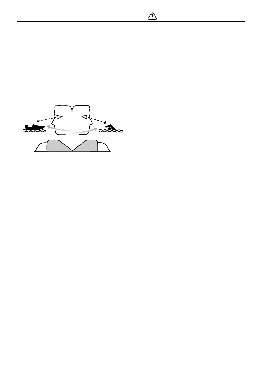
People in the water
Always watch carefully for people in the water, such as swimmers, skiers, or divers,
whenever the engine is running. When someone is in the water near the boat, shift into
neutral and stop the engine.
Stay away from swimming areas. Swimmers
can be hard to see.
The propeller can keep moving even when
the motor is in neutral. Stop the engine when
a person is in the water near you.
EMU33752
Passengers
Consult your boat manufacturer’s instructions for details about appropriate passenger
locations in your boat and be sure all passengers are positioned properly before accelerating and when operating above an idle
speed. Standing or sitting in non-designated
locations may result in being thrown either
overboard or within the boat due to waves,
wakes, or sudden changes in speed or direction. Even when people are positioned properly, alert your passengers if you must make
any unusual maneuver. Always avoid jumping waves or wakes.
EMU33762
Overloading
Do not overload the boat. Consult the boat
capacity plate or boat manufacturer for maximum weight and number of passengers. Be
sure that weight is properly distributed according to the boat manufacturer’s instruc-
2
Safety information
ZMU06025
tions. Overloading or incorrect weight
distribution can compromise the boats handling and lead to an accident, capsizing or
swamping.
EMU33773
Avoid collisions
Scan constantly for people, objects, and other boats. Be alert for conditions that limit your
visibility or block your vision of others.
Operate defensively at safe speeds and keep
a safe distance away from people, objects,
and other boats.
Do not follow directly behind other boats or
waterskiers.
Avoid sharp turns or other maneuvers that
make it hard for others to avoid you or understand where you are going.
Avoid areas with submerged objects or
shallow water.
Ride within your limits and avoid aggres-
sive maneuvers to reduce the risk of loss of
control, ejection, and collision.
Take early action to avoid collisions. Re-
member, boats do not have brakes, and
stopping the engine or reducing throttle
can reduce the ability to steer. If you are not
sure that you can stop in time before hitting
an obstacle, apply throttle and turn in another direction.
EMU33791
Weather
Stay informed about the weather. Check
weather forecasts before boating. Avoid
boating in hazardous weather.
EMU33881
Passenger training
Make sure at least one other passenger is
trained to operate the boat in the event of an
emergency.
EMU33891
Boating safety publications
Be informed about boating safety. Additional
publications and information can be obtained
from many boating organizations.
EMU33601
Laws and regulations
Know the marine laws and regulations where
you will be boating- and obey them. Several
sets of rules prevail according to geographic
location, but all are basically the same as the
International Rules of the Road.
3
General information
1
ZMU07733
EMU25172
Identification numbers record
EMU25185
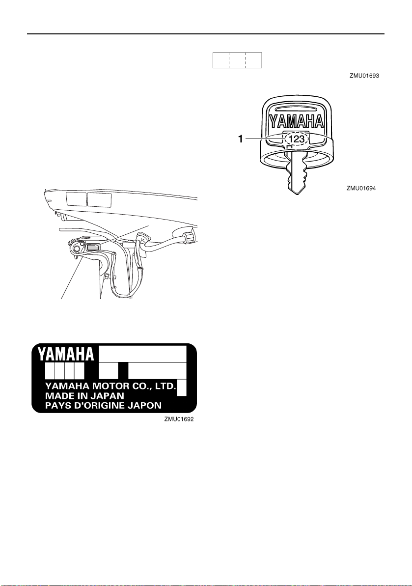
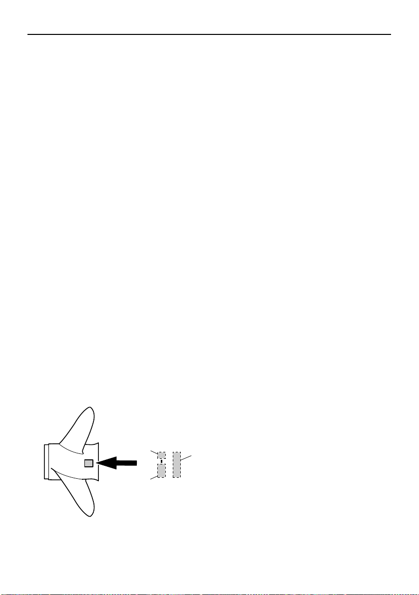
Outboard motor serial number
The outboard motor serial number is
stamped on the label attached to the port
side of the clamp bracket.
Record your outboard motor serial number in
the spaces provided to assist you in ordering
spare parts from your Yamaha dealer or for
reference in case your outboard motor is stolen.
1. Outboard motor serial number location
EMU25192
Key number
If a main key switch is equipped with the motor, the key identification number is stamped
on your key as shown in the illustration. Record this number in the space provided for
reference in case you need a new key.
1. Key number
EMU37292
EC Declaration of Conformity
(DoC)
This outboard motor conforms to certain portions of the European Parliament directive relating to machinery.
Each conformed outboard motor accompanied with EC DoC.EC DoC contains the following information;
Name of Engine Manufacture
Model name
Product code of model (Approved model
code)
Code of conformed directives
EMU25207
CE Marking
Outboard motors affixed with this “CE”marking conform with the directives of;
2006/42/EC, 94/25/EC - 2003/44/EC and
2004/108/EC.
4
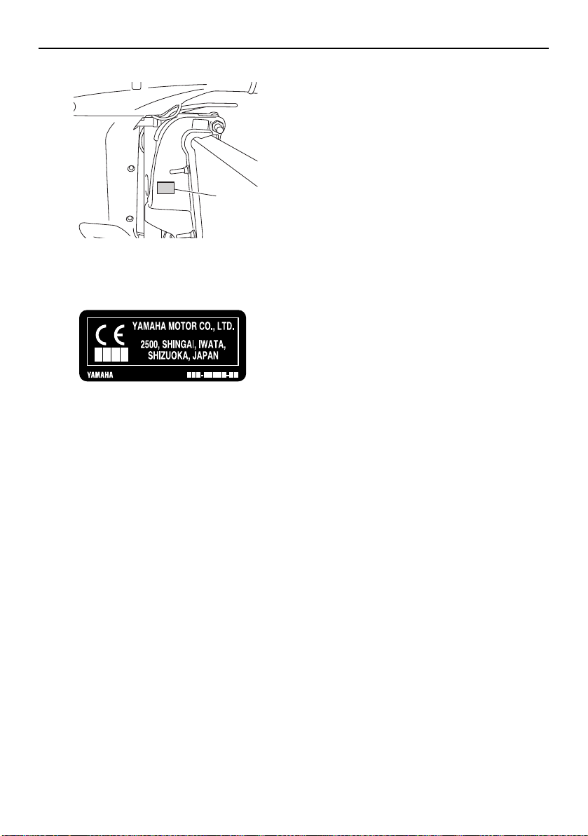
1. CE marking location
1
ZMU07868
ZMU06040
General information
5
General information
2
1
3
ZMU07865
EMU33524
Read manuals and labels
Before operating or working on this outboard motor:
Read this manual.
Read any manuals supplied with the boat.
Read all labels on the outboard motor and the boat.
If you need any additional information, contact your Yamaha dealer.
EMU33834
Warning labels
If these labels are damaged or missing, contact your Yamaha dealer for replacements.
6
General information
WARNING
WARNING
1
2
ZMU06191
3
ZMU05710
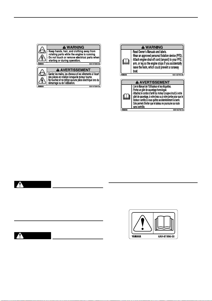
EMU34652
Contents of labels
The above warning labels mean as follows.
1
EWM01682
Keep hands, hair, and clothing away
from rotating parts while the engine is
running.
Do not touch or remove electrical parts
when starting or during operation.
2
EWM01672
Read Owner’s Manuals and labels.
Wear an approved personal flotation de-
vice (PFD).
Attach engine shut-off cord (lanyard) to
your PFD, arm, or leg so the engine
stops if you accidentally leave the helm,
which could prevent a runaway boat.
EMU33851
Other labels
7
General information
ZMU05696
ZMU05664
ZMU05665
ZMU05666
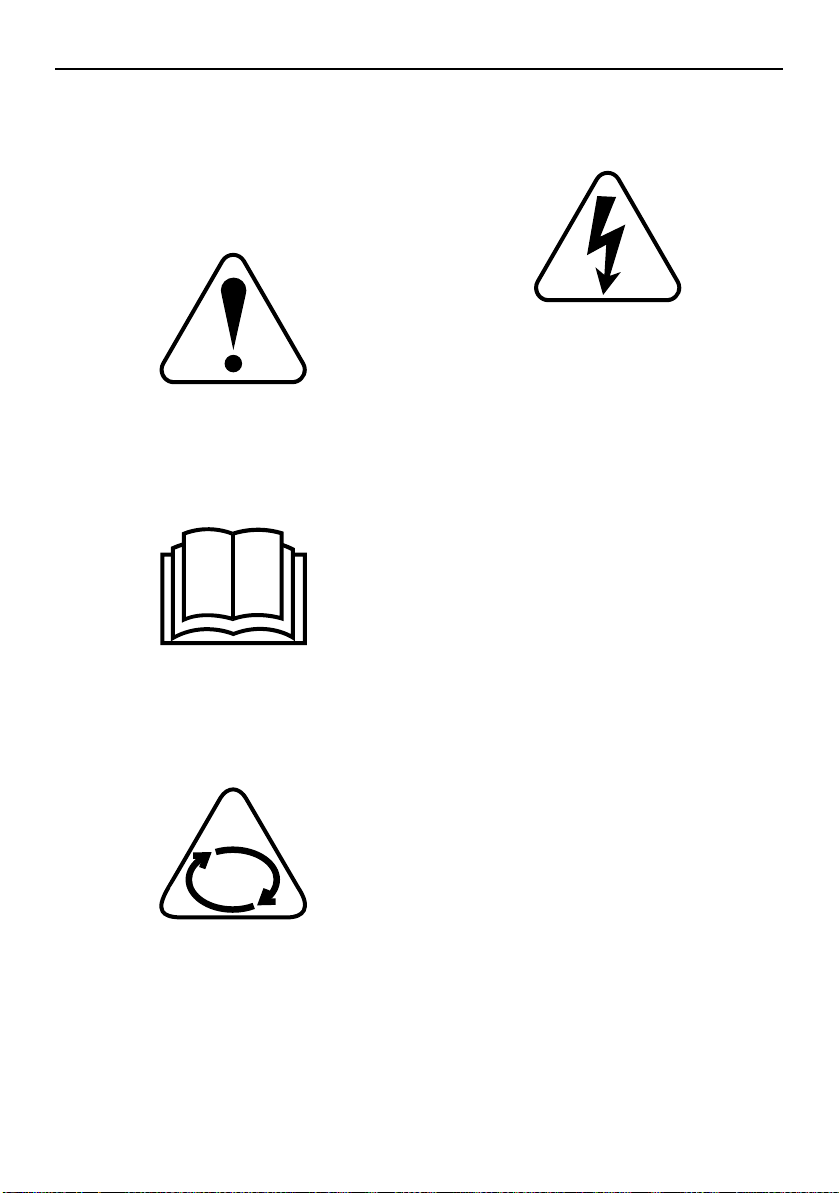
EMU35133
Symbols
The following symbols mean as follows.
Notice/Warning
Read Owner’s Manual
Electrical hazard
Hazard caused by continuous rotation
8

Specifications and requirements
TIP:
EMU40501
Specifications
“(SUS)” indicates that the specification is for
the outboard motor when it is equipped with
a stainless steel propeller.
EMU2821U
Dimension and weight:
Overall length:
920 mm (36.2 in)
Overall width:
548 mm (21.6 in)
Overall height L:
F175AET 1742 mm (68.6 in)
F200FET 1742 mm (68.6 in)
F200FET1 1742 mm (68.6 in)
Overall height X:
1869 mm (73.6 in)
Motor transom height L:
F175AET 516 mm (20.3 in)
F200FET 516 mm (20.3 in)
F200FET1 516 mm (20.3 in)
Motor transom height X:
643 mm (25.3 in)
Dry weight (SUS) L:
F175AET 224 kg (494 lb)
F200FET 226 kg (498 lb)
F200FET1 226 kg (498 lb)
Dry weight (SUS) X:
F175AET 225 kg (496 lb)
F200FET 227 kg (500 lb)
F200FET1 227 kg (500 lb)
FL200FET 227 kg (500 lb)
FL200FET1 227 kg (500 lb)
Performance:
Full throttle operating range:
5000–6000 r/min
Rated power:
F175AET 128.7 kW (175 HP)
F200FET 147.1 kW (200 HP)
F200FET1 147.1 kW (200 HP)
FL200FET 147.1 kW (200 HP)
FL200FET1 147.1 kW (200 HP)
Idle speed (in neutral):
650–750 r/min
Power unit:
Type:
4-stroke DOHC L4 16 valves
Total displacement:
2785 cm³ (169.9 c.i.)
Bore × stroke:
96.0 × 96.2 mm (3.78 × 3.79 in)
Ignition system:
TCI
Spark plug (NGK):
LFR6A-11
Spark plug gap:
1.0–1.1 mm (0.039–0.043 in)
Steering system:
Remote steering
Starting system:
Electric starter
Starting carburetion system:
Fuel injection
Valve clearance IN (cold engine):
0.17–0.24 mm (0.0067–0.0094 in)
Valve clearance EX (cold engine):
0.31–0.38 mm (0.0122–0.0150 in)
Cold cranking amps (CCA/EN):
640–1080 A
Min. rated capacity (20HR/IEC):
80 Ah
Maximum generator output:
50 A
Lower unit:
Gear shift positions:
Forward-neutral-reverse
9
Specifications and requirements
WARNING
WARNING
Gear ratio:
1.86 (26/14)
Trim and tilt system:
Power trim and tilt
Propeller mark:
F175AET M/T
F200FET M/T
F200FET1 M/T
FL200FET ML/TL
FL200FET1 ML/TL
Fuel and oil:
Recommended fuel:
F175AET Regular unleaded gasoline
F200FET Premium unleaded gasoline
F200FET1 Premium unleaded gasoline
FL200FET Premium unleaded gasoline
FL200FET1 Premium unleaded gasoline
Min. research octane number (RON):
F175AET 90
F200FET 94
F200FET1 94
FL200FET 94
FL200FET1 94
Recommended engine oil:
YAMALUBE 4 or 4-stroke outboard
motor oil
Recommended engine oil grade 1:
SAE 10W-30/10W-40/5W-30
API SE/SF/SG/SH/SJ/SL
Engine oil quantity (without oil filter
replacement):
4.3 L (4.55 US qt, 3.78 Imp.qt)
Engine oil quantity (with oil filter
replacement):
4.5 L (4.76 US qt, 3.96 Imp.qt)
Lubrication system:
Wet sump
Recommended gear oil:
YAMALUBE outboard gear oil or Hypoid
gear oil
Recommended gear oil grade:
SAE 90 API GL-4
Gear oil quantity:
0.980 L (1.036 US qt, 0.862 Imp.qt)
Tightening torque:
Spark plug:
28 Nm (2.86 kgf-m, 20.7 ft-lb)
Propeller nut:
54 Nm (5.51 kgf-m, 39.8 ft-lb)
Engine oil drain bolt:
27 Nm (2.75 kgf-m, 19.9 ft-lb)
Engine oil filter:
18 Nm (1.84 kgf-m, 13.3 ft-lb)
Noise and vibration level:
Operator sound pressure level (ICOMIA
39/94):
80.8 dB(A)
EMU33555
Installation requirements
EMU33565
Boat horsepower rating
EWM01561
Overpowering a boat can cause severe instability.
Before installing the outboard motor(s), confirm that the total horsepower of your outboard motor(s) does not exceed the boats
maximum horsepower rating. See the boat’s
capacity plate or contact the manufacturer.
EMU40491
Mounting outboard motor
EWM02501
Improper mounting of the outboard mo-
tor could result in hazardous conditions
such as poor handling, loss of control,
or fire hazards.
Because the outboard motor is very
heavy, special equipment and training is
required to mount it safely.
10
Specifications and requirements
NOTICE
WARNING
ZMU07305
Your dealer or other person experienced in
proper rigging should mount the outboard
motor using correct equipment and complete
rigging instructions. For further information,
see page 46.
EMU41593
Yamaha Security System
ECM02461
The Yamaha Security System is sold in
conformity with the relevant laws and regulations regarding radio wave transmission. Therefore, if this product is used
outside the country where it was sold, it
may violate the laws or regulations regarding radio wave transmission in the
country it is used in. For details, consult
your Yamaha dealer.
The outboard motor with this label is
equipped with the Yamaha Security System
to protect against theft, which consists of the
receiver and remote control transmitter. The
engine can not be started if the security system is in the lock mode, and only be started
in the unlock mode. Consult your Yamaha
dealer for installation of the receiver.
EMU33582
Remote control requirements
EWM01581
If the engine starts in gear, the boat can
move suddenly and unexpectedly, possibly causing a collision or throwing
passengers overboard.
If the engine ever starts in gear, the
start-in-gear protection device is not
working correctly and you should discontinue using the outboard. Contact
your Yamaha dealer.
The remote control unit must be equipped
with a start-in-gear protection device(s). This
device prevents the engine from starting unless it is in neutral.
EMU25695
Battery requirements
EMU25723
Battery specifications
Cold cranking amps (CCA/EN):
640–1080 A
Min. rated capacity (20HR/IEC):
80 Ah
The engine cannot be started if battery voltage is too low.
EMU36291
Mounting battery
Mount the battery holder securely in a dry,
well-ventilated, vibration-free location in the
boat. WARNING! Do not put flammable
items, or loose heavy or metal objects in
the same compartment as the battery.
Fire, explosion or sparks could result.
[EWM01821]
EMU36301
Multiple batteries
To connect multiple batteries, such as for
multiple engine configurations or for an accessory battery, consult your Yamaha dealer
about battery selection and correct wiring.
11
Specifications and requirements
ZMU07044
3
1
2
EMU41602
Propeller selection
Next to selecting an outboard motor, selecting the right propeller is one of the most important purchasing decisions a boater can
make. The type, size, and design of your propeller have a direct impact on acceleration,
top speed, fuel economy, and even engine
life. Yamaha designs and manufactures propellers for every Yamaha outboard motor and
every application.
Your Yamaha dealer can help you select the
right propeller for your boating needs. Select
a propeller that will allow the engine to reach
the middle or upper half of the operating
range at full throttle with the maximum boatload. Generally, select a larger pitch propeller
for a smaller operating load and a smaller
pitch propeller for a heavier load. If you carry
loads that vary widely, select the propeller
that lets the engine run in the proper range for
your maximum load but remember that you
may need to reduce your throttle setting to
stay within the recommended engine speed
range when carrying lighter loads.
Yamaha recommends to use a propeller suitable for the “Shift Dampener System (SDS)”.
For further information, consult your Yamaha
dealer.
To check the propeller, see page 82.
3. Type of propeller (propeller mark)
EMU36312
Counter rotation models
Standard outboard motors rotate clockwise.
Counter rotation models rotate counterclockwise and are typically used in multiple motor
setups.
On counter rotation models, be sure to use a
propeller intended for counterclockwise rotation. These propellers are identified with the
letter “L” after the size indication on the propeller. WARNING! Never use a standard
propeller with a counter rotation motor, or
a counter rotation propeller with a standard motor. Otherwise the boat could go
in the direction opposite of that expected
(for example, reverse instead of forward),
which could lead to an accident.
[EWM01811]
For instructions on propeller removal and installation, see page 83 and 83.
EMU25771
Start-in-gear protection
Yamaha outboard motors or Yamaha-approved remote control units are equipped
with start-in-gear protection device(s). This
feature permits the engine to be started only
when it is in neutral. Always select neutral before starting the engine.
EMU41953
Engine oil requirements
Select an oil grade according to the average
temperatures in the area where the outboard
motor will be used.
1. Propeller diameter in inches
2. Propeller pitch in inches
12
Specifications and requirements
NOTICE
ZMU06854
122˚F
50˚C
104
40
86
30
68
SAE API
SE
SF
SG
SH
SJ
SL
20
50
10
32
0
14
-10
-4
-20
10W–30
10W–40
5W–30
ZMU06855
122˚F
50˚C
104
40
86
30
68
SAE API
SH
SJ
SL
20
50
10
32
0
14
-10
-4
-20
15W–40
20W–40
20W–50
Recommended engine oil:
YAMALUBE 4 or 4-stroke outboard
motor oil
Recommended engine oil grade 1:
SAE 10W-30/10W-40/5W-30
API SE/SF/SG/SH/SJ/SL
Recommended engine oil grade 2:
SAE 15W-40/20W-40/20W-50
API SH/SJ/SL
Engine oil quantity (without oil filter
replacement):
4.3 L (4.55 US qt, 3.78 Imp.qt)
Engine oil quantity (with oil filter replacement):
4.5 L (4.76 US qt, 3.96 Imp.qt)
If oil grades listed under Recommended engine oil grade 1 are not available, select an alternative oil grade listed under
Recommended engine oil grade 2.
Recommended engine oil grade 1
Recommended engine oil grade 2
EMU36361
Fuel requirements
EMU44461
Gasoline
Use a good quality gasoline that meets the
minimum octane rating.
Recommended fuel:
F175AET Regular unleaded gasoline
F200FET Premium unleaded gasoline
F200FET1 Premium unleaded gasoline
FL200FET Premium unleaded gasoline
FL200FET1 Premium unleaded gasoline
Min. research octane number (RON):
F175AET 90
F200FET 94
F200FET1 94
FL200FET 94
FL200FET1 94
ECM01982
Do not use leaded gasoline. Leaded
gasoline can seriously damage the engine.
Avoid getting water and contaminants in
the fuel tank. Contaminated fuel can
cause poor performance or engine damage. Use only fresh gasoline that has
been stored in clean containers.
Gasohol
There are two types of gasohol: gasohol containing ethanol (E10) and that containing
methanol. Ethanol can be used if the ethanol
content does not exceed 10% and the fuel
meets the minimum octane ratings. E85 is a
fuel containing 85% ethanol and must not be
used in your outboard motor. All ethanol
blends containing more than 10% ethanol
can cause fuel system damage or cause engine starting and running problems. Yamaha
13
Specifications and requirements
1
ZMU07735
does not recommend gasohol containing
methanol because it can cause fuel system
damage or engine performance problems.
It is recommended that you install a waterseparating marine fuel filter assembly (10 micron minimum) between your boat’s fuel tank
and outboard motor when using ethanol. Ethanol is known to allow moisture to be absorbed into boat fuel tanks and systems.
Moisture in the fuel can cause corrosion of
metallic fuel system components, starting
and running complaints and require additional fuel system maintenance.
EMU36331
Anti-fouling paint
A clean hull improves boat performance. The
boat bottom should be kept as clean of marine growth as possible. If necessary, the boat
bottom can be coated with an anti-fouling
paint approved for your area to inhibit marine
growth.
Do not use anti-fouling paint which includes
copper or graphite. These paints can cause
more rapid engine corrosion.
EMU36353
Emergency equipment
Keep the following items onboard in case
there is trouble with the outboard motor.
A tool kit with assorted screwdrivers, pliers,
wrenches (including metric sizes), and
electrical tape.
Waterproof flashlight with extra batteries.
An extra engine shut-off cord (lanyard) with
clip.
Spare parts, such as an extra set of spark
plugs.
Consult your Yamaha dealer for details.
EMU39001
Emission control information
The following labels are affixed to outboard
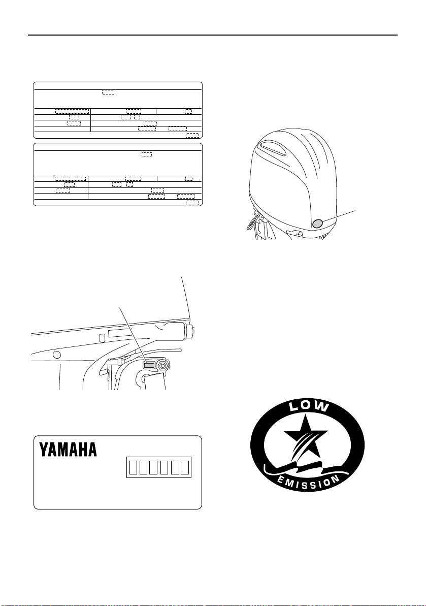
motors that conform to US regulations.
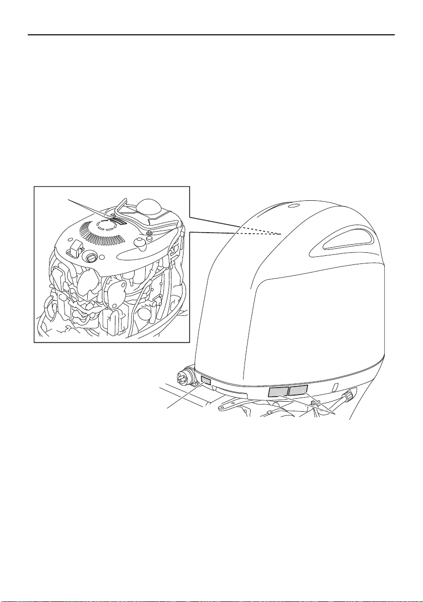
EMU25232
This engine conforms to U.S. Environmental
Protection Agency (EPA) regulations for marine SI engines. See the label affixed to your
engine for details.
EMU31562
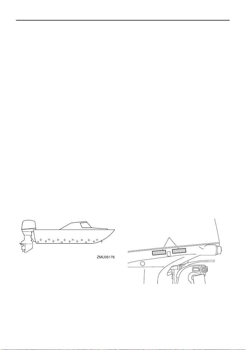
Approval label of emission control certificate
This label is attached to the bottom cowling.
New Technology; (4-stroke) MFI
EMU40302
Outboard motor disposal re-
quirements
Never illegally discard (dump) the outboard
motor. Yamaha recommends consulting the
dealer about discarding the outboard motor.
14
1. Approval label location
Specifications and requirements
ZMU06895
EMISSION CONTROL INFORMATION MFI
THIS ENGINE CONFORMS TO CALIFORNIA AND U.S. EPA EXHAUST
REGULATIONS FOR SI MARINE ENGINES. REFER TO THE OWNER'S
MANUAL FOR MAINTENANCE SPECIFICATIONS AND ADJUSTMENTS.
MEETS U.S. EPA EVAP STANDARDS USING CERTIFIED COMPONENTS.
FAMILY:
DISPLACEMENT: liters
SPARK PLUG:
FUEL: GASOLINE
FELs(HC+NOx / CO)
: / g/kW-hr MAX POWER: kW
IDLE SPEED: ± rpm IN NEUTRAL
SPARK PLUG GAP (mm):
VALVE LASH (mm) IN: EX:
YAMAHA MOTOR CO.,LTD.
INFORMATION ANTIPOLLUTION MFI
CE MOTEUR EST CONFORME AUX NORMES D’ÉMISSIONS EPA DES É.-U. ET DE LA
CALIFORNIE POUR MOTEURS MARINS À ÉTINCELLE. POUR LES SPÉCIFICATIONS ET LES
RÉGLAGES À EFFECTUER, CONSULTEZ LE MANUEL DU PROPRIÉTAIRE. INSTALLÉ AVEC
LES COMPOSANTS HOMOLOGUÉS, IL SATISFAIT AUX NORMES EVAP EPA DES É.-U.
YAMAHA MOTOR CO.,LTD.
FAMILLE :
CYLINDRÉE : litre
BOUGIE :
CARBURANT : ESSENCE
FELs(HC+NOx / CO)
: / g/kW-h PUISS. MAX. : kW
RALENTI : ± tr/mm AU POINT MORT
BOUGIE-ÉCARTEMENT (mm) :
JEU DE SOUPAPES (mm) ADM: ÉCH:
1
ZMU07736
Manufactured:
ZMU04346
1
ZMU07737
ZMU01702
EMU25275
Star labels
Your outboard motor is labeled with a California Air Resources Board (CARB) star label.
See below for a description of your particular
label.
EMU39202
Manufactured date label
This label is attached to the clamp bracket.
1. Manufactured date label location
1. Star labels location
EMU40331
One Star—Low Emission
The one-star label identifies engines that
meet the Air Resources Board’s Personal
Watercraft and Outboard marine engine 2001
exhaust emission standards. Engines meeting these standards have 75% lower emissions than conventional carbureted twostroke engines. These engines are equivalent
to the U.S. EPA’s 2006 standards for marine
engines.
15
Specifications and requirements
ZMU01703
ZMU01704
ZMU05663
EMU40341
Two Stars—Very Low Emission
The two-star label identifies engines that
meet the Air Resources Board’s Personal
Watercraft and Outboard marine engine 2004
exhaust emission standards. Engines meeting these standards have 20% lower emissions than One Star-Low-Emission engines.
EMU40351
Three Stars—Ultra Low Emission
The three-star label identifies engines that
meet the Air Resources Board’s Personal
Watercraft and Outboard marine engine 2008
exhaust emission standards or the Sterndrive
and Inboard marine engine 2003-2008 exhaust emission standards. Engines meeting
these standards have 65% lower emissions
than One Star-Low-Emission engines.
emission standards. Personal Watercraft and
Outboard marine engines may also comply
with these standards. Engines meeting these
standards have 90% lower emissions than
One Star-Low-Emission engines.
EMU33862
Four Stars—Super Ultra Low Emission
The four-star label identifies engines that
meet the Air Resources Board’s Sterndrive
and Inboard marine engine 2009 exhaust
16
Components
TIP:
6
4
3
10
2
1
7
9
2
5
8
ZMU07738
EMU2579Z
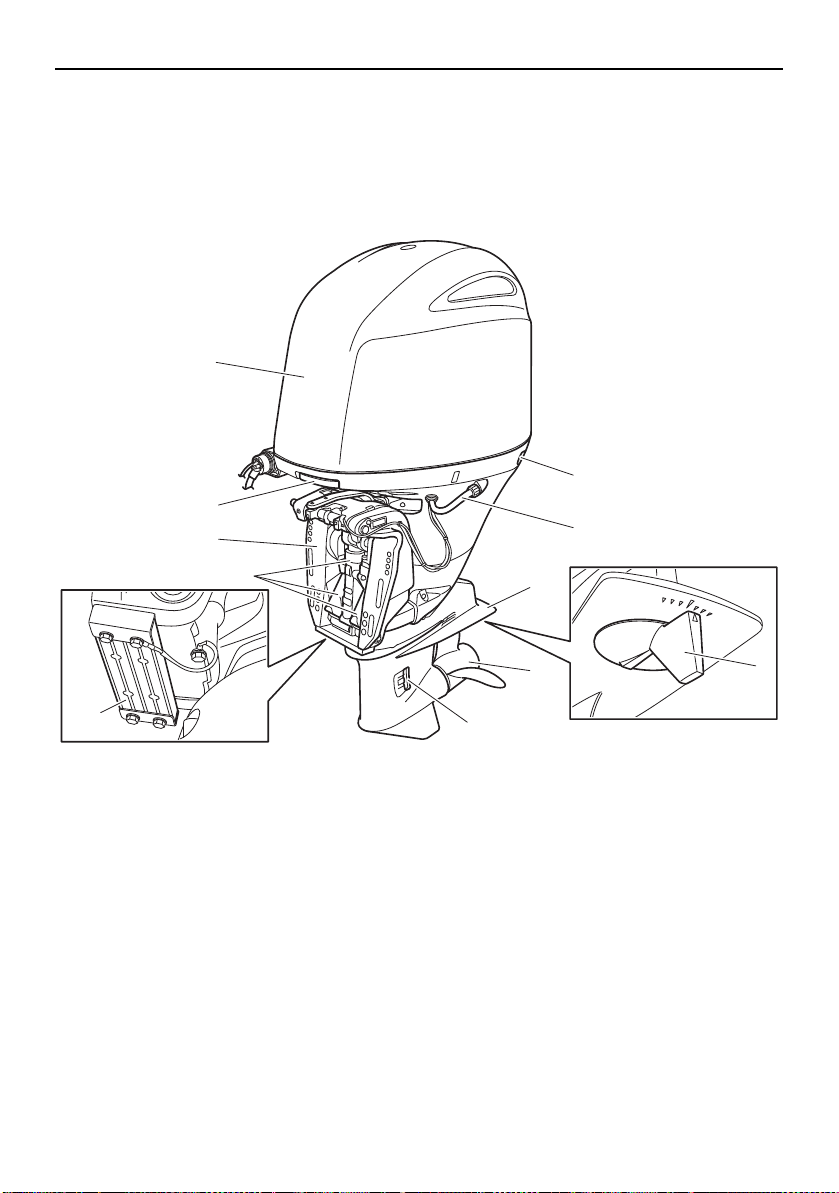
Components diagram
* May not be exactly as shown; also may not be included as standard equipment on all models
(order from dealer).
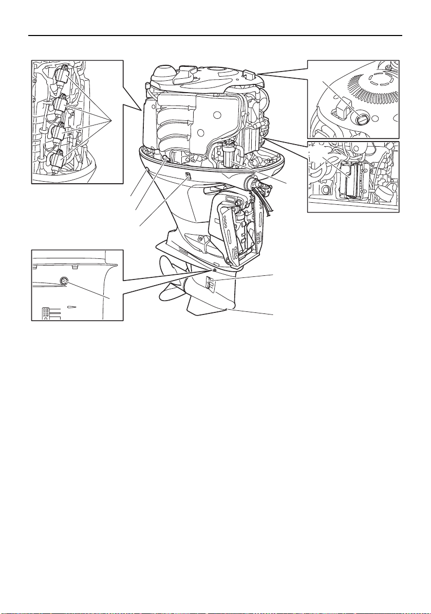
1. Top cowling
2. Cowling lock lever
3. Clamp bracket
4. Power trim and tilt unit
5. Anode
6. Flushing device
7. Anti-cavitation plate
8. Trim tab (anode)
9. Propeller*
10.Cooling water inlet
17
Components
8
10
9
2
4
5
3
6
7
1
ZMU07739
1. Ignition coil
2. Oil dipstick
3. Cowling lock lever
4. Power trim and tilt switch
5. Oil level plug
6. Oil filler cap
7. Fuse box
8. Fuel filter
9. Cooling water inlet
10.Gear oil drain screw
18

Components
TRIP TIME BATT
Km/h
knot
mph
km
mile
SPEED
YAMAHA
set
mode
SET MODE
SET MODE
1
76
245
8
12 1411
9
13
3
1615
10
ZMU07869
1. Remote control box (side mount type)*
2. Remote control box (binnacle mount type)*
3. Remote control box (binnacle mount type)*
4. Switch panel (for use with binnacle type)*
5. Switch panel (for use with binnacle type)*
6. Digital tachometer*
7. Digital speedometer*
8. Fuel management meter*
9. Tachometer unit (Square type)*
10.Tachometer unit (Round type)*
11.Speedometer unit (Square type)*
12.Speed & fuel meter unit (Square type)*
13.Speed & fuel meter unit (Round type)*
14.Fuel management meter unit (Square type)*
15.Remote control transmitter
16.Receiver
19
Components
NOTICE
TIP:
ZMU06455
EMU38592
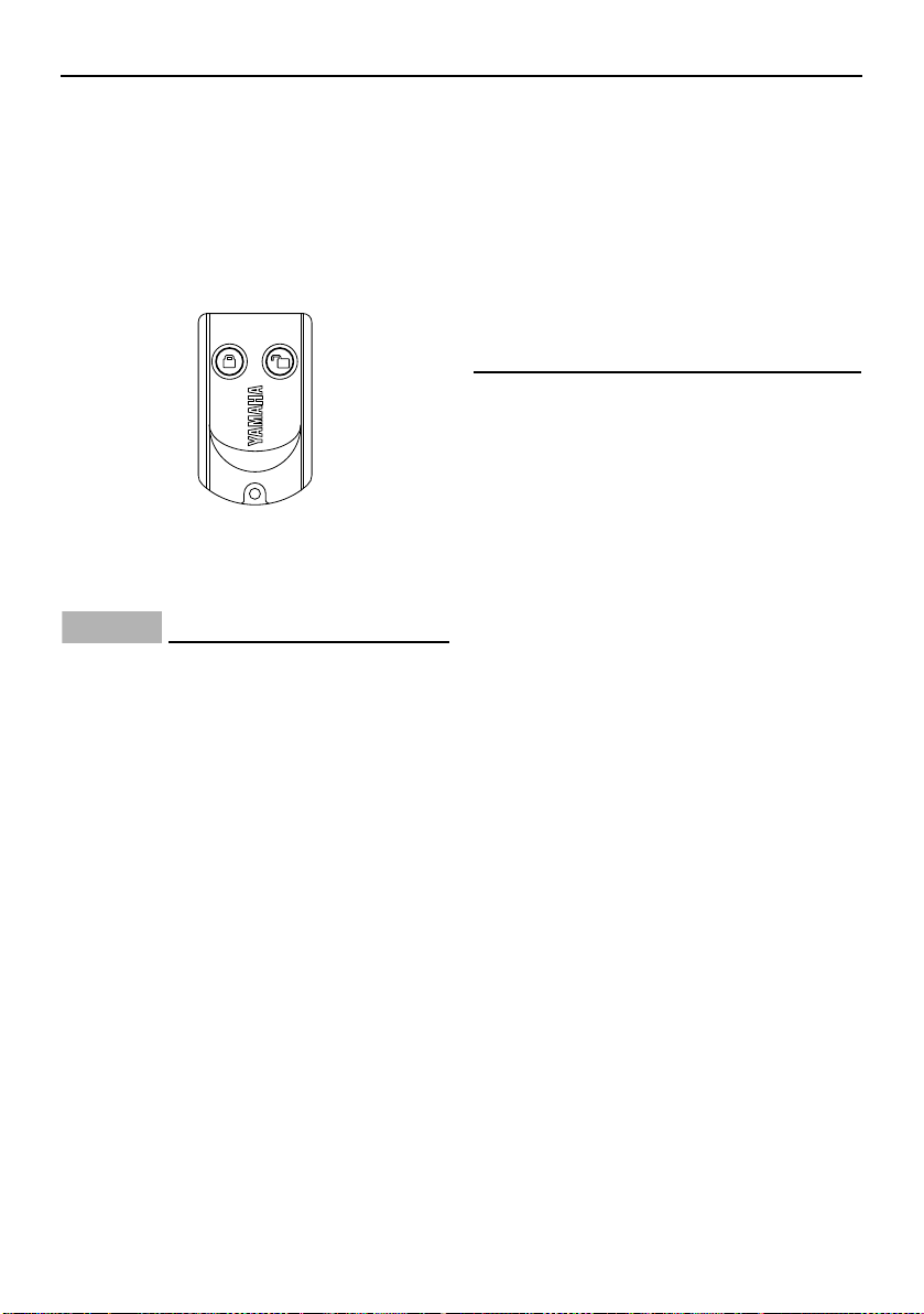
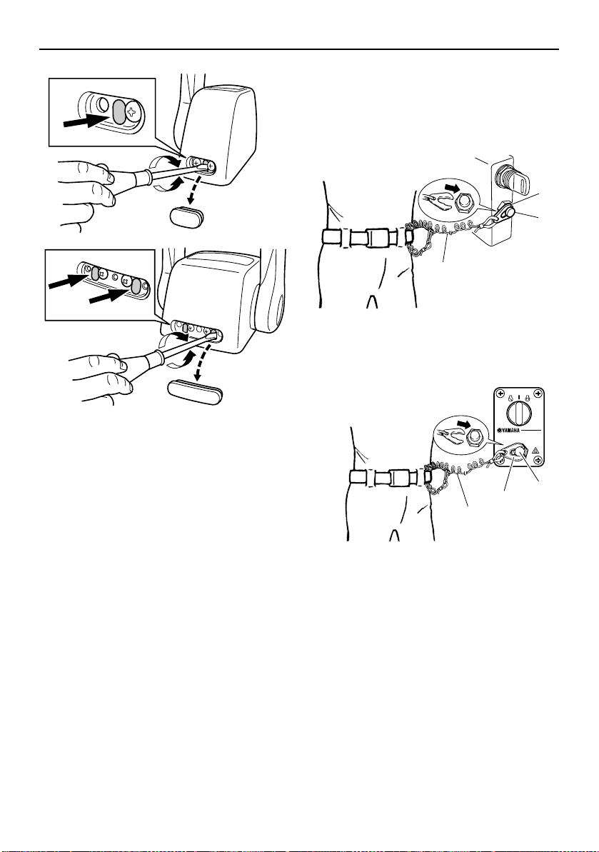
Remote control transmitter
The lock and unlock modes of the Yamaha
Security System are selected using the remote control transmitter. While the engine is
running, input from the remote control transmitter is not received.
Store the remote control transmitter carefully
so it will not be lost.
ECM02101
The remote control transmitter is not
completely waterproof. Do not submerge the transmitter or operate it underwater. If the transmitter is
submerged, dry it with a soft, dry cloth,
and then check that it is operating properly. If the transmitter is not operating
properly, contact a Yamaha dealer.
Keep the remote control transmitter
away from high temperatures and do
not place it in direct sunlight.
Do not drop the remote control trans-
mitter, subject it to strong shocks, or
place any heavy items on it.
Use a soft, dry cloth to clean the remote
control transmitter. Do not use detergent, alcohol, or other chemicals.
Do not attempt to disassemble the re-
mote control transmitter yourself. Otherwise, the transmitter may not operate
properly. If the transmitter needs a new
battery, contact a Yamaha dealer.
If you have lost the remote control trans-
mitter, consult your Yamaha dealer.
Keep the least 2 transmitters at all the
time. If you have lost both transmitters,
consult your Yamaha dealer.
Since the receiver is programmed to rec-
ognize the internal code from this transmitter only, the security system setting can
only be changed with this transmitter. If the
remote control transmitter does not operate properly, contact a Yamaha dealer.
Replace the battery cell after 1 year, and
every two years thereafter as a standard
measure.
Refer to local hazardous waste regulations
when disposing of transmitter batteries.
The Yamaha Security System permits to
register up to 5 remote control transmitters. Consult your yamaha dealer for details.
EMU38602
Receiver
The receiver control the ECM (Electronic control module) to prevent the engine from starting. Consult your Yamaha dealer for
installation of the receiver.
EMU38612
Yamaha Security System lock and unlock mode
The Yamaha Security System settings are selected by pressing the lock or unlock button
on the remote control transmitter briefly.
20
Components
12
ZMU06456
2
1
3
4
ZMU04572
2
3
2
1
4
ZMU04569
1. Lock button
2. Unlock button
LOCK
When the lock button on the remote control
transmitter is pressed briefly, the beeper
sounds once. This indicates the lock mode is
selected and the engine cannot be started.
The lock mode is selected only when the
main switch is in the “ ” (off) position. The
engine cranks but can not be started while
the Yamaha Security System is on lock mode.
UNLOCK
When the unlock button on the remote control transmitter is pressed briefly, the beeper
sounds twice. This indicates the unlock mode
is selected and the engine can be started.
Yam ah a
Security
System
mode
Lock 1 beep “ ” NO
Unlock 2 beeps
EMU26182
Number
of beeps
Main
switch
“”/
“”
Engine
can be
started
YES
Remote control box
The remote control lever actuates both the
shifter and the throttle. The electrical switches are mounted on the remote control box.
1. Power trim and tilt switch
2. Remote control lever
3. Neutral interlock trigger
4. Neutral throttle lever
5. Main switch
6. Engine shut-off switch
7. Throttle friction adjuster
1. Power trim and tilt switch
2. Remote control lever
3. Free accelerator
4. Throttle friction adjuster
1. Remote control lever
21
Components
N
1
F
7
6
2
R
3
4
4
6
5
7
5
ZMU04573
1
2
3
ZMU06988
2. Power trim and tilt switch
3. Free accelerator
4. Throttle friction adjuster
EMU26191
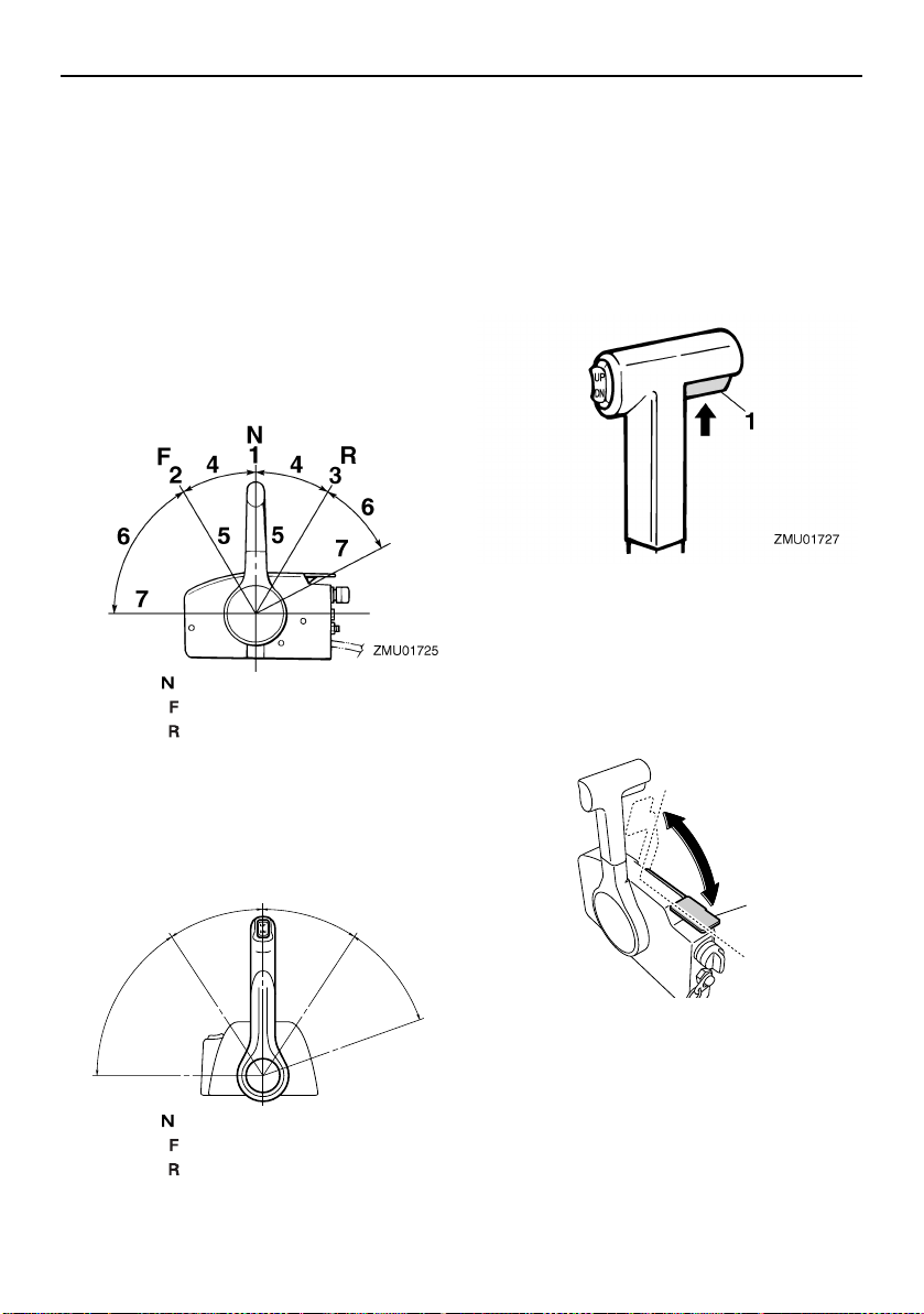
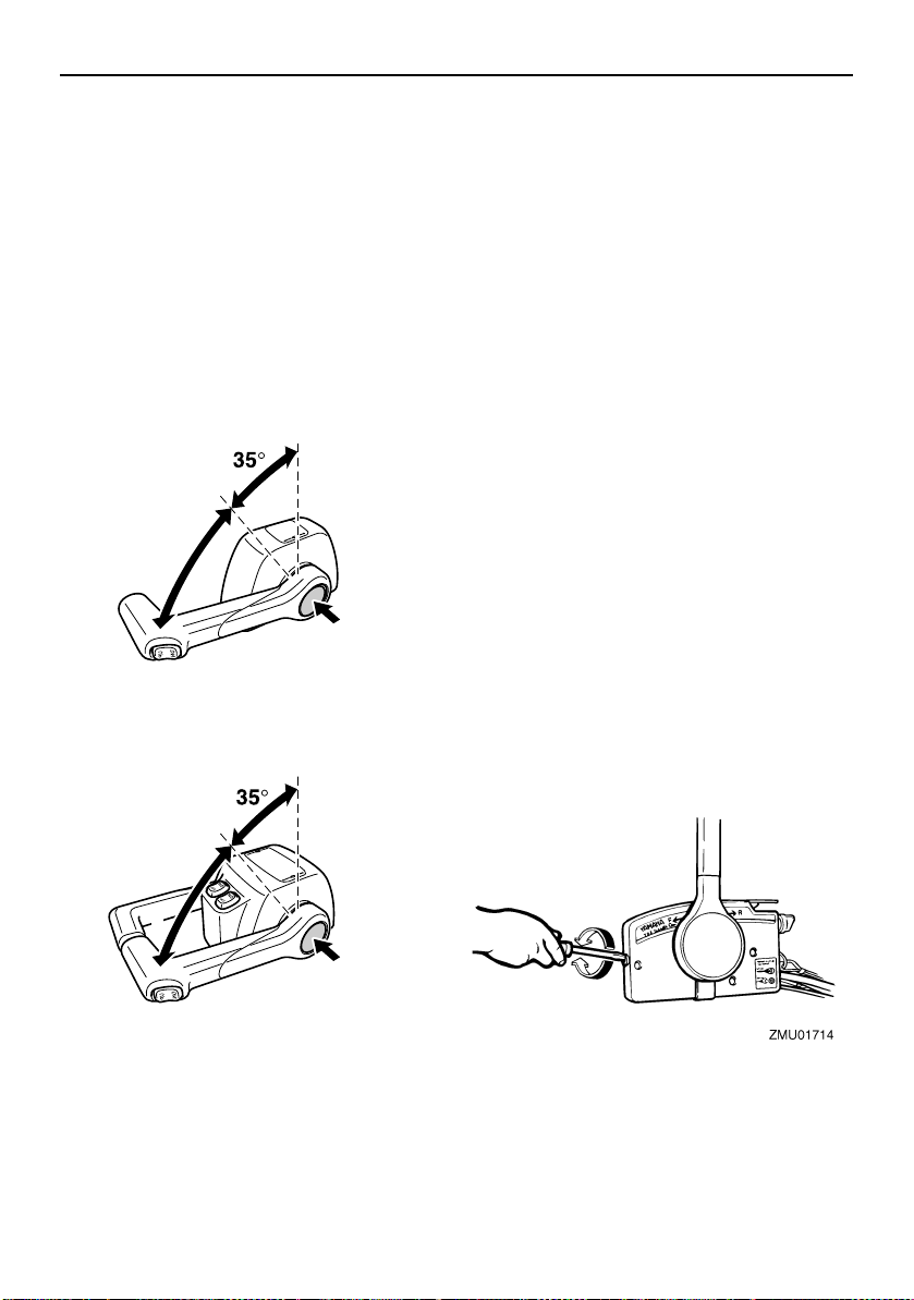
Remote control lever
Moving the lever forward from the neutral position engages forward gear. Pulling the lever
back from neutral engages reverse. The engine will continue to run at idle until the lever
is moved about 35° (a detent can be felt).
Moving the lever farther opens the throttle,
and the engine will begin to accelerate.
1. Neutral “ ”
2. Forward “ ”
3. Reverse “ ”
4. Shift
5. Fully closed
6. Throttle
7. Fully open
4. Shift
5. Fully closed
6. Throttle
7. Fully open
EMU26202
Neutral interlock trigger
To shift out of neutral, first pull the neutral interlock trigger up.
1. Neutral interlock trigger
EMU26213
Neutral throttle lever
To open the throttle without shifting into either forward or reverse, put the remote control lever in the neutral position and lift the
neutral throttle lever.
1. Neutral “ ”
2. Forward “ ”
3. Reverse “ ”
22
1. Fully open
2. Fully closed
3. Neutral throttle lever
Components
TIP:
TIP:
N
ZMU04576
1
3
2
1
3
2
ZMU04575
The neutral throttle lever will operate only
when the remote control lever is in neutral.
The remote control lever will operate only
when the neutral throttle lever is in the closed
position.
EMU26234
Free accelerator
To open the throttle without shifting into either forward or reverse, push the free accelerator button and move the remote control
lever.
1. Fully open
2. Fully closed
3. Free accelerator
The free accelerator button can only be
pushed when the remote control lever is in
the neutral position.
After the button is pushed, the throttle be-
gins to open after the remote control lever
is moved at least 35°.
After using the free accelerator, return the
remote control lever to the neutral position.
The free accelerator button will return automatically to its set position. The remote
control will then engage forward and reverse normally.
EMU25977
Throttle friction adjuster
A friction device provides adjustable resistance to movement of the throttle grip or the
remote control lever, and can be set according to operator preference.
To increase resistance, turn the adjuster
clockwise. To decrease resistance, turn the
adjuster counterclockwise. WARNING! Do
not overtighten the friction adjuster. If
there is too much resistance, it could be
difficult to move the remote control lever
or throttle grip, which could result in an
accident.
[EWM00033]
1. Fully open
2. Fully closed
3. Free accelerator
23
Components
ZMU04563
ZMU04646
ZMU06982
2
3
1
ZMU04565
1
2
3
When constant speed is desired, tighten the
adjuster to maintain the desired throttle setting.
EMU25996
Engine shut-off cord (lanyard) and clip
The clip must be attached to the engine shutoff switch for the engine to run. The cord
should be attached to a secure place on the
operator’s clothing, or arm or leg. Should the
operator fall overboard or leave the helm, the
cord will pull out the clip, stopping ignition to
the engine. This will prevent the boat from
running away under power. WARNING! At-
tach the engine shut-off cord to a secure
place on your clothing, or your arm or leg
while operating. Do not attach the cord to
clothing that could tear loose. Do not route the cord where it could become entangled, preventing it from functioning. Avoid
accidentally pulling the cord during normal operation. Loss of engine power
means the loss of most steering control.
24
Also, without engine power, the boat
could slow rapidly. This could cause people and objects in the boat to be thrown
forward.
1. Engine shut-off cord (lanyard)
2. Clip
3. Engine shut-off switch
1. Engine shut-off cord (lanyard)
2. Clip
3. Engine shut-off switch
[EWM00123]
Loading...