


F15A
Yamaha F15A, F15, F9.9C, FT9.9D, F15MHX Service Manual
...
F15A
F9.9C, FT9.9D
66M-28197-Z8-C1
WORLD WIDE
F15
USA/CANADA
SERVICE MANUAL
MANUEL D’ENTRETIEN
WARTUNGSANLEITUNG
MANUAL DE SERVICIO
E
F
D
ES

NOTICE
This manual has been prepared by the Yamaha Motor Company, Ltd. primarily for use by
Yamaha dealers and their trained mechanics when performing maintenance procedures and
repairs to Yamaha equipment. It has been written to suit the needs of persons who have a
basic understanding of the mechanical and electrical concepts and procedures inherent in
the work, for without such knowledge attempted repairs or service to the equipment could
render it unsafe or unfit for use.
Because the Yamaha Motor Company, Ltd. has a policy of continuously improving its products, models may differ in detail from the descriptions and illustrations given in this publication. Use only the latest edition of this manual. Authorized Yamaha dealers are notified periodically of modifications and significant changes in specifications and procedures, and these
are incorporated in successive editions of this manual.
F15A/F9.9C/FT9.9D
(F15)
SERVICE MANUAL
©1998 Yamaha Motor Co.,Ltd.
1st Edition, April 1998
All rights reserved.
No part of this publication may be
reproduced or transmitted in any form or
by any means including photocopying and
recording without the written permission of
the copyright holder.
Such written permission must also be
obtained before any part of this publication
is stored in a retrieval system of any nature.
Printed in Japan
P/N 66M-28197-Z8-C1
A10001-0*
E

ES
D
F
La Yamaha Motor Company a élaboré
ce manuel à l’attention des concessionnaires Yamaha et de leurs mécaniciens
pour leurs travaux d’entretien et de réparation sur du matériel Yamaha. Ce
manuel s’adresse à des personnes disposant de connaissances de base solides en mécanique et en électricité
Sans lesquelles elles risqueraient, au
cours de leurs travaux de réparation ou
d’entretien, de rendre le matériel inapte ou dangereux à l’utilisation.
La politique de la Yamaha Motor Company Ltd. visant à l’amélioration
constante de ses produits, il est possible que le modèle devant faire l’objet
d’une réparation ne corresponde pas
exactement au modèle présenté. N’utilisez que l’édition la plus récente de ce
manuel. Les concessionnaires agréés
Yamaha sont régulièrement informés
de toutes les modifications importantes
apportées à Notre matériel. Il est tenu
compte de ces modifications dans les
éditions successives de ce manuel.
Dieses Handbuch wurde von der
Yamaha Motor Company vorrangig
zur Verwendung durch die YamahaVertragshändler und ihre qualifizierten Mechaniker geschrieben. Es ist
nicht möglich, den gesamten Ausbildungsumfang von Mechanikern
in einem einzigen Handbuch zusammenzufassen.
Darum werden in diesem Handbuch
Grundkenntnisse des mechanischen und elektrischen Aufbaus
und der zur Wartung nötigen Arbeitsmethoden vorausgesetzt. Versuchte Wartungs- und Reparaturarbeiten ohne solche Kenntnisse
könnten den Außenbordmotor unsicher und/oder verwendungsunfähig machen.
Die Yamaha Motor Company, Ltd.
ist immer danach bestrebt, alle von
Yamaha hergestellten Modelle zu
verbessern. Spezifikationen oder
Verfahren werden allen YamahaVertragshändlern mitgeteilt und
werden ggf. in zukünftigen Ausgaben dieses Handbuchs erscheinen.
Este manual ha sido preparado por Yamaha Motor Company y va dirigido a
los concesionarios Yamaha y a sus mecánicos cualificados para realizar los
procedimientos de mantenimiento y las
reparaciones de los equipos Yamaha.
Está redactado de forma que pueda satisfacer las necesidades de aquellas
personas que poseen unos conocimientos básicos de los conceptos y procedimientos mecánicos y eléctricos inherentes a dichos trabajos de mantenimiento y reparación, ya que de no poseer tales conocimientos, las posibles
reparaciones o mantenimiento del
equipo podrían afectar adversamente
su seguridad y operatividad.
Puesto que Yamaha Motor Company
Ltd. sigue una política de mejora continua de sus productos, puede que las especificaciones de los modelos no coincidan con algunos aspectos de las descripciones e ilustraciones contenidos
en esta publicación. Utilice únicamente la versión más reciente de este manual. Los concesionarios autorizados
Yamaha reciben periódicamente información relacionada a las modificaciones y cambios significativos introducidos en las especificaciones y los procedimientos de los equipos, información
que se incorporará a las ediciones sucesivas de este manual.
AVANT PROPOS
F15A/F9.9C/FT9.9D
(F15)
MANUEL D’ENTRETIEN
©1998 Yamaha Motor Co., Ltd.
1 ère édition, avril 1998
Tous droits réservés.
Toute reproduction ou
transmission de ce manuel, même
partielle, par quelque procédé que
ce soit, y compris par photocopie
ou enregistrement, requiert
l’accord écrit préalable de la
Yamaha Motor Co., Ltd.
Imprimé au Japon
P/N 66M-28197-Z8-C1
EINFÜHRUNG
F15A/F9.9C/FT9.9D
(F15)
WARTUNGSHANDBUCH
©1998 Yamaha Motor Co., Ltd.
1. Ausgabe, April 1998
Alle Rechte vorbehalten.
Diese Veröffentlichung darf auch
teilweise in keiner Weise oder
durch irgendein Verfahren ohne
die schriftliche Genehmigung des
Inhabers des Urheberrechts
reproduziert oder übertragen
werden. Dies gilt auch für
Fotokopien und Aufzeichnungen.
Die schriftliche Genehmigung ist
vor der ÜbErnahme in irgendein
Informationssystem einzuholen.
Gedruckt in Japan
P/N 66M-28197-Z8-C1
AVISO
F15A/F9.9C/FT9.9D
(F15)
MANUAL DE SERVICIO
©1998 Yamaha Motor Co., Ltd.
1ª Edición, abril 1998
Reservados todos los derechos.
Queda prohibida la reproducción o
transmisión de esta publicación, ya
sea en su totalidad o en parte, y por
cualquier medio, incluido su
fotocopiado o grabación, sin el
consentimiento por escrito del
titular del derecho de copyright.
También deberá obtenerse este con-
sentimiento antes de proceder al
almacenamiento de cualquier parte
de esta publicación en un
sistema de búsqueda documental
de cualquier naturaleza.
Impreso en Japón
P/N° 66M-28197-Z8-C1

E
HOW TO USE THIS MANUAL
MANUAL FORMAT
All of the procedures in this manual are organized in a sequential, step-by-step format. The
information has been compiled to provide the mechanic with an easy to read, handy reference that contains comprehensive explanations of all disassembly, repair, assembly, and
inspection operations.
In this revised format, the condition of a faulty component will precede an arrow symbol and
the course of action required will follow the symbol, e.g.,
8 Bearings
Pitting/Scratches → Replace.
To assist you to find your way through this manual, the section title and major heading are
given at the top of every page.
IILUSTRATIONS
The illustrations within this service manual represent all of the designated models.
CROSS REFERENCE
The cross references have been kept to a minimum. Cross references will direct you to the
appropriate section or chapter.

ES
D
F
MODE D’UTILISA-
TION DU MANUEL
PRESENTATION DU MANUEL
Dans ce manuel, tous les procédés sont
décrits pas à pas. Les informations ont
été condensées pour fournir au mécanicien un guide pratique et facile à lire,
contenant des explications claires pour
tous les procédés de démontage, réparation, remontage et vérification.
Dans ce nouveau format, l’état d’un
composant défectueux est suivi d’une
flèche qui indique les mesures à
prendre. Exemple:
9 Roulements
Piqûres/Endommagement →
Changer.
Pour plus de facilité, le titre de chapitre ainsi que le titre de section sont
repris en tête de chaque page.
ILLUSTRATIONS
Les illustrations contenues dans ce manuel de service représentent tous les
modèles concernés.
REFERENCES CROISEES
Les références ont été réduites à un minimum. Les références croisées vous
renvoient directement à la section ou
au chapitre approprié.
LEITFADEN FÜR
DIESES HANDBUCH
AUFBAU DES HANDBUCHS
Dieses Handbuch enthält Beschreibungen von Arbeitsverfahren, die
für Demontage, Reparatur, Montage, Einstellung und Inspektion eingesetzt werden. Alle Arbeiten werden der Reihe nach schrittweise
dargestellt.
Der geänderte Aufbau gibt den Zustand eines schadhaften Bauteils
vor einem Pfeilsymbol an. Die erforderlichen Maßnahmen werden
nach dem Symbol beschrieben, z.B:
9 Lager
Lochfraß/Beschädigung →
Ersetzen.
Um Ihnen das Auffinden von gewünschten Stellen in dem Handbuch zu erleichtern, ist oben auf jeder Seite der Titel des Kapitels und
betreffenden Abschnitts aufgeführt.
ABBILDUNGEN
Die Abbildungen in diesem Kundendiensthandbuch beziehen sich
auf alle Modelle.
QUERVERWEISE
Querverweise sind auf ein Mindestmaß begrenzt. Sie führen Sie zum
entsprechenden Abschnitt oder Kapitel.
COMO UTILIZAR
ESTE MANUAL
FORMATO DEL MANUAL
Todos los procedimientos de este manual están preparados en un formato
secuencial de paso a paso.
La información ha sido compilada para
ofrecer al mecánico una referencia útil
y de fácil lectura que contiene amplias
explicaciones de todos los procedimientos de desmontaje, reparación,
montaje, e inspecciones.
En este formato revisado, la condición
de un componente averiado irá precedida de un símbolo de flecha y el curso
de la acción requerida seguirá al símbolo, como por ejemplo:
9 Cojinetes
Picaduras/Daños → Reemplazar.
Para ayudarle a orientarse a través de
este manual, en la parte superior de
cada página figuran el título
de la sección y el encabezamiento
principal.
FIGURAS
Las figuras que aparecen en este manual de servicio representan todos los
modelos designados.
REFERENCIAS CRUZADAS
Las referencias cruzadas se han reducido al mínimo y le dirigen al apartado o
capítulo correcto.
IMPORTANT INFORMATION
In this Service Manual particularly important information is distinguished in the following
ways.
Q The Safety Alert Symbol means ATTENTION! BECOME ALERT! YOUR SAFETY IS
INVOLVED!
w
Failure to follow WARNING instructions could result in severe injury or death to the machine
operator, a bystander, or a person inspecting or repairing the outboard motor.
cC
A CAUTION indicates special precautions that must be taken to avoid damage to the outboard motor.
NOTE:
A NOTE provides key information to make procedures easier or clearer.
E
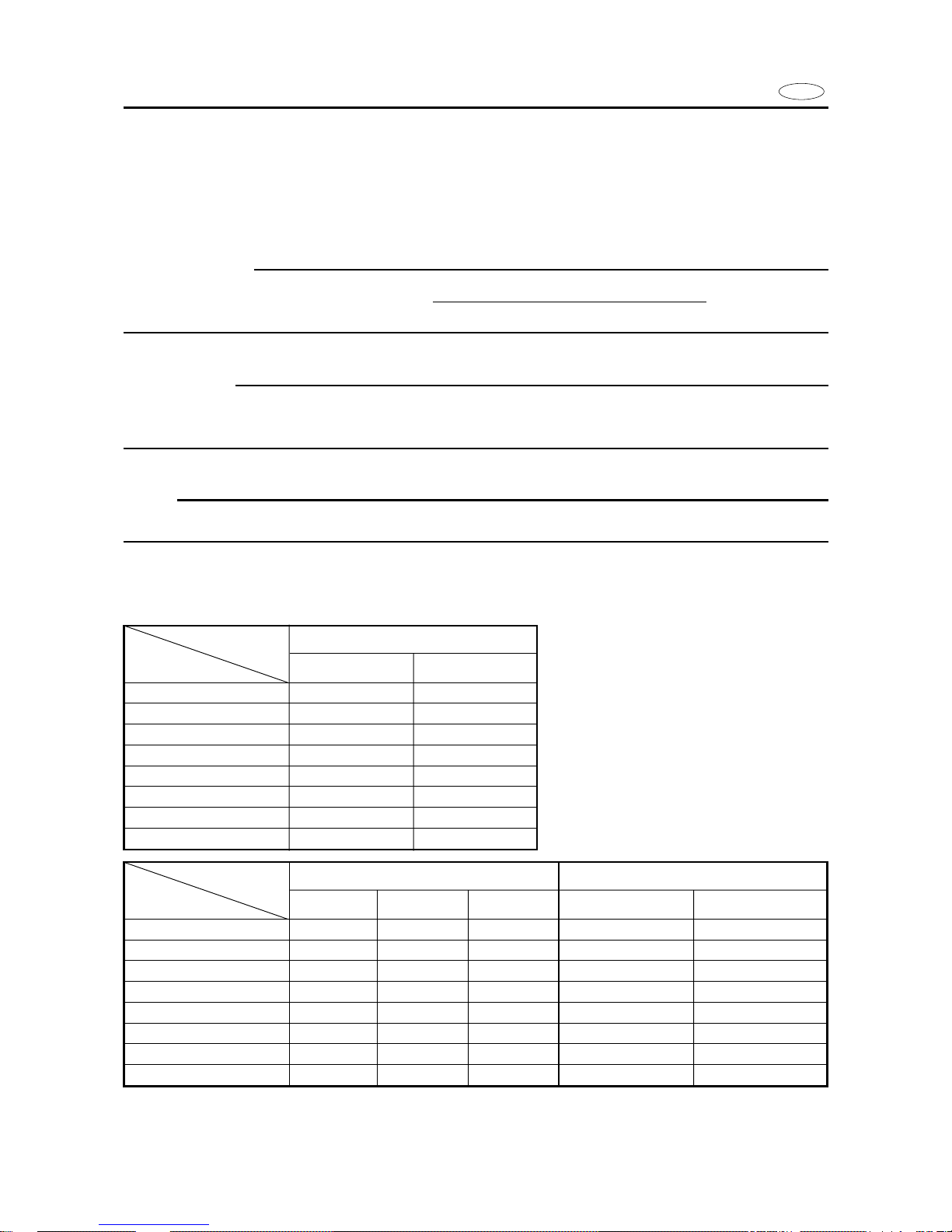
SPECIFIC COMPARISON
The following tables show the main differences in specifications between models.
Model USA/CANADA
Item F15MHX F15EHX
Steering friction 11
Steering hook — —
Ring gear 1 () 1
Lighting current
AC 6A (12V-80W)
—
Charging current — 10A
Rectifier — —
Rectifier/regulator — 6G8-A1
Fuse — 20A
CANADA
—
Model EUROPE OCEANIA
Item F15AMH F15AEH F15AE F15AMH F15AEH
Steering friction — — — — —
Steering hook — — 1 ——
Ring gear — 11 — 1
Lighting current 12V-80W — —
AC 6A (12V-80W)
—
Charging current 6A 6A 10A — 10A
Rectifier — 6G1 — — —
Rectifier/regulator 6J8 — 6G8-A1 — 6G8-A1
Fuse — 10A 20A — 20A

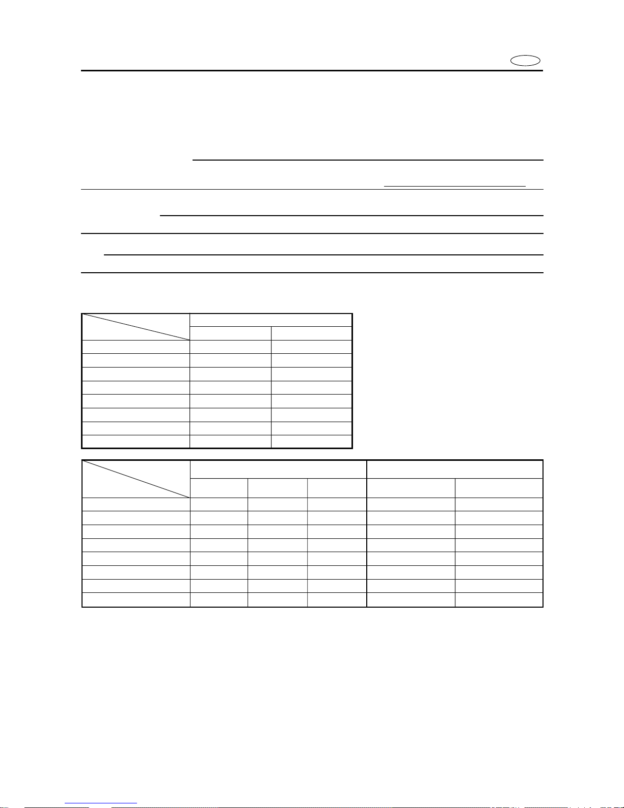
Model EUROPE
Item F9.9CMH F9.9CEH F9.9CE
Steering friction — — —
Steering hook — — 1
Ring gear — 11
Lighting current 12V-80W — —
Charging current 6A 6A 10A
Rectifier — 6G1 —
Rectifier/regulator 6J8 — 6G8-A1
Fuse — 10A 20A
Model EUROPE OCEANIA
Item FT9.9DMH FT9.9DEH FT9.9DE FT9.9DMH FT9.9DE
Steering friction 111 1 1
Steering hook — — 1 — 1
Ring gear — 11 — 1
Lighting current — — — — —
Charging current 10A 10A 10A 10A 10A
Rectifier — — — — —
Rectifier/regulator 6G8-A1 6G8-A1 6G8-A1 6G8-A1 6G8-A1
Fuse — 20A 20A — 20A
E
INFORMATIONS IMPORTANTES
Les informations plus particulièrement importantes présentées dans ce manuel de service sont mises en évidence de la façon suivante.
Q Ce symbole signale un danger : ATTENTION DANGER ! SOYEZ ATTENTIF ! VOTRE SECURITE EST EN JEU !
XG
Le respect des consignes AVERTISSEMENT est impératif, faute de quoi le conducteur, toute personne se trouvant à proximité ou le personnel chargé de l’entretien du moteur hors-bord risquerait d’être grièvement voire mortellement blessé.
fF
ATTENTION indique les consignes qui doivent être respectées afin d’éviter d’endommager le moteur hors-bord.
N.B.:
N.B. donne des informations importantes qui facilitent et expliquent les différentes opérations.
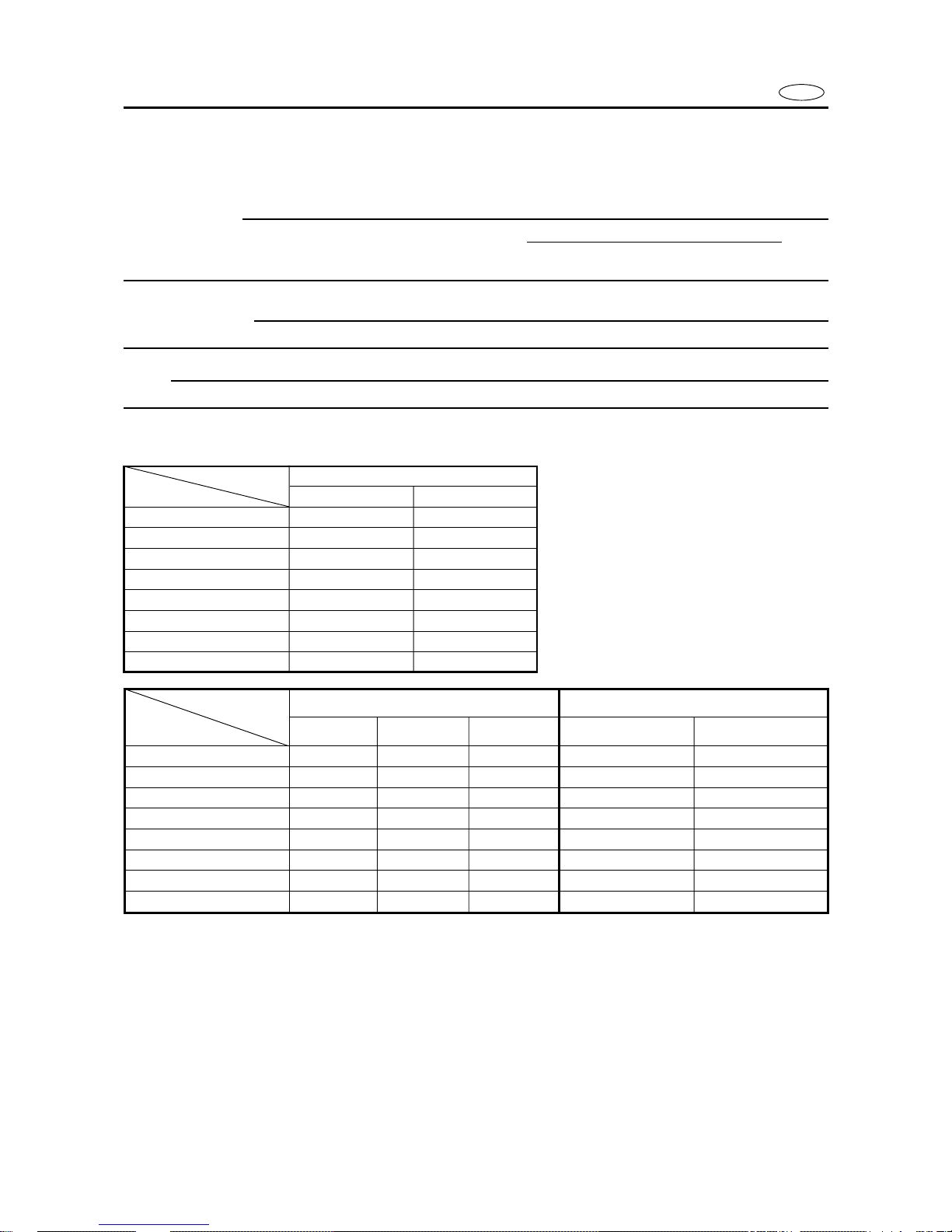
COMPARAISONS SPECIFIQUES
Les tableaux suivants montrent les principales différences de spécification entre modèles.
Modèle E.-U./CANADA
Désignation F15MHX F15EHX
Friction de la direction 11
Support de barre franche — —
Couronne 1 () 1
Courant d’éclairage AC 6A(12V-80W) —
Courant de charge — 10A
Redresseur — —
Redresseur/régulateur — 6G8-A1
Fusible — 20A
CANADA
—
Modèle EUROPE OCEANIE
Désignation F15AMH F15AEH F15AE F15AMH F15AEH
Friction de la direction — —— — —
Support de barre franche — — 1 ——
Couronne — 11 — 1
Courant d’éclairage 12V-80W — — AC 6A (12V-80W) —
Courant de charge 6A 6A 10A — 10A
Redresseur — 6G1 — — —
Redresseur/régulateur 6J8 — 6G8-A1 — 6G8-A1
Fusible — 10A 20A — 20A
F

F
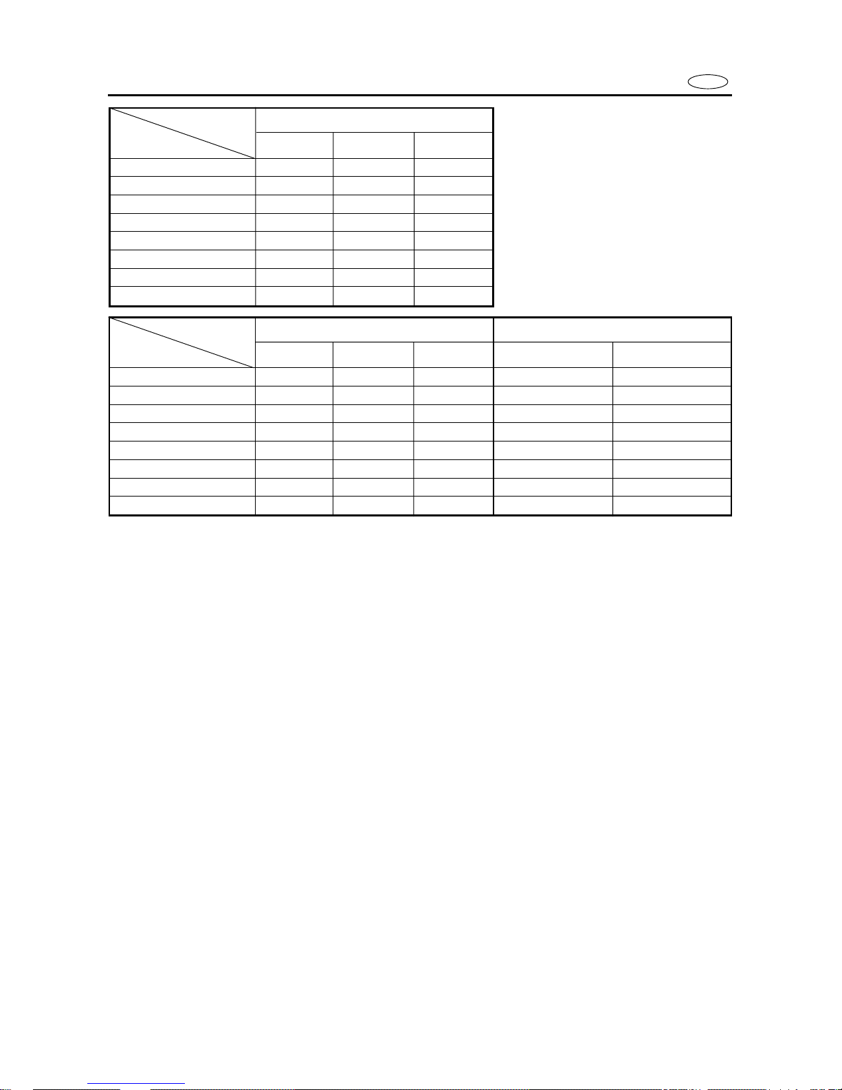
Modèle EUROPE
Désignation F9.9CMH F9.9CEH F9.9CE
Friction de la direction — — —
Support de barre franche — — 1
Couronne — 11
Courant d’éclairage 12V-80W — —
Courant de charge 6A 6A 10A
Redresseur — 6G1 —
Redresseur/régulateur 6J8 — 6G8-A1
Fusible — 10A 20A
Modèle EUROPE OCEANIE
Désignation FT9.9DMH FT9.9DEH FT9.9DE FT9.9DMH FT9.9DE
Friction de la direction 111 1 1
Support de barre franche — — 1 — 1
Couronne — 11 — 1
Courant d’éclairage — — — — —
Courant de charge 10A 10A 10A 10A 10A
Redresseur — — — — —
Redresseur/régulateur 6G8-A1 6G8-A1 6G8-A1 6G8-A1 6G8-A1
Fusible — 20A 20A — 20A

D
WICHTIGER HINWEIS
In diesem Kundendiensthandbuch werden wichtige Hinweise folgendermaßen hervorgehoben.
Q Das Achtungsschild bedeutet: ACHTUNG! AUFGEPASST! ES GEHT UM IHRE SICHERHEIT!
W
Ein Nichtbefolgen der Warnhinweise kann ernsthafte Verletzungen und sogar den Tod zur Folge haben. Dies gilt für Bediener, Zuschauer und am Motor arbeitende Techniker gleichermaßen.
dD
DUnter dieser Überschrift ergehen Hinweise auf Vorsichtsmaßnahmen zum Schutze des Motors.
HINWEIS:
Hier geht es um nützliche Tips und Hinweise.
SPEZIFISCHE VERGLEICHE
Die folgenden Tabellen zeigen die Hauptunterschiede in den technischen Daten verschiedener Modelle.
Modell USA/KANADA
Teil F15MHX F15EHX
Schublenkantrieb 11
Lenkhaken — —
Tellerrad 1 () 1
Lichtstrom AC 6A (12V-80W) —
Ladestrom — 10A
Gleichrichter — —
Gleichrichter/Regler — 6G8-A1
Sicherung — 20A
KANADA
—
Modell EUROPA OZEANIEN
Teil F15AMH F15AEH F15AE F15AMH F15AEH
Schublenkantrieb ——— — —
Lenkhaken — — 1 ——
Tellerrad — 11 — 1
Lichtstrom 12V-80W — —
AC 6A (12V-80W)
—
Ladestrom 6A 6A 10A — 10A
Gleichrichter — 6G1 — — —
Gleichrichter/Regler 6J8 — 6G8-A1 — 6G8-A1
Sicherung — 10A 20A — 20A

Modell EUROPE
Teil F9.9CMH F9.9CEH F9.9CE
Schublenkantrieb ———
Lenkhaken ——1
Tellerrad — 11
Lichtstrom 12V-80W — —
Ladestrom 6A 6A 10A
Gleichrichter — 6G1 —
Gleichrichter/Regler 6J8 — 6G8-A1
Sicherung — 10A 20A
Modell EUROPA OZEANIEN
Teil FT9.9DMH FT9.9DEH FT9.9DE FT9.9DMH FT9.9DE
Schublenkantrieb 111 1 1
Lenkhaken ——1 — 1
Tellerrad — 11 — 1
Lichtstrom ——— — —
Ladestrom 10A 10A 10A 10A 10A
Gleichrichter ——— — —
Gleichrichter/Regler 6G8-A1 6G8-A1 6G8-A1 6G8-A1 6G8-A1
Sicherung — 20A 20A — 20A
D
INFORMACION IMPORTANTE
En este manual de servicio, la información especialmente importante se distingue de las siguientes maneras.
Q El símbolo de seguridad significa ¡ATENCION! ¡PERMANEZCA ALERTA! ¡SU SEGURIDAD ESTA EN JUEGO!
r
La no observancia de las instrucciones contenidas en un AVISO puede provocar graves lesiones o incluso la muerte del operador del motor fuera borda, de las personas que se encuentren a su alrededor o de la persona que inspeccione o repare el
motor fuera borda.
bB
Una PRECAUCION indica cuidados especiales que deben tomarse para evitar dañar el motor fuera borda.
NOTA:
Una NOTA ofrece información clave para facilitar o aclarar los procedimientos.
COMPARACIONES ESPECIFICAS
Las tablas siguientes muestran las diferencias principales existentes entre los modelos en lo que a especificaciones se refiere.
Modelo EE.UU./CANADA
Elemento F15MHX F15EHX
Fricción de la dirección 11
Gancho de la dirección — —
Anillo dentado 1() 1
Corriente de alumbrado AC 6A (12V-80W) —
Corriente de carga — 10A
Rectificador — —
Rectifire/regurator — 6G8-A1
Fusible — 20A
CANADA
—
ES
Modelo EUROPA OCEANIA
Elemento F15AMH F15AEH F15AE F15AMH F15AEH
Fricción de la dirección — — — — —
Gancho de la dirección — — 1 ——
Anillo dentado — 11 — 1
Corriente de alumbrado 12V-80W — —
AC 6A (12V-80W)
—
Corriente de carga 6A 6A 10A — 10A
Rectificador — 6G1 — — —
Regulador/rectificador 6J8 — 6G8-A1 — 6G8-A1
Fusible — 10A 20A — 20A
ES
Modelo EUROPE
Elemento F9.9CMH F9.9CEH F9.9CE
Fricción de la dirección — — —
Gancho de la dirección — — 1
Anillo dentado — 11
Corriente de alumbrado 12V-80W — —
Corriente de carga 6A 6A 10A
Rectificador — 6G1 —
Regulador/rectificador 6J8 — 6G8-A1
Fusible — 10A 20A
Modelo EUROPA OCEANIA
Elemento FT9.9DMH FT9.9DEH FT9.9DE FT9.9DMH FT9.9DE
Fricción de la dirección 111 1 1
Gancho de la dirección — — 1 — 1
Anillo dentado — 11 — 1
Corriente de alumbrado — — — — —
Corriente de carga 10A 10A 10A 10A 10A
Rectificador — — — — —
Regulador/rectificador 6G8-A1 6G8-A1 6G8-A1 6G8-A1 6G8-A1
Fusible — 20A 20A — 20A
E
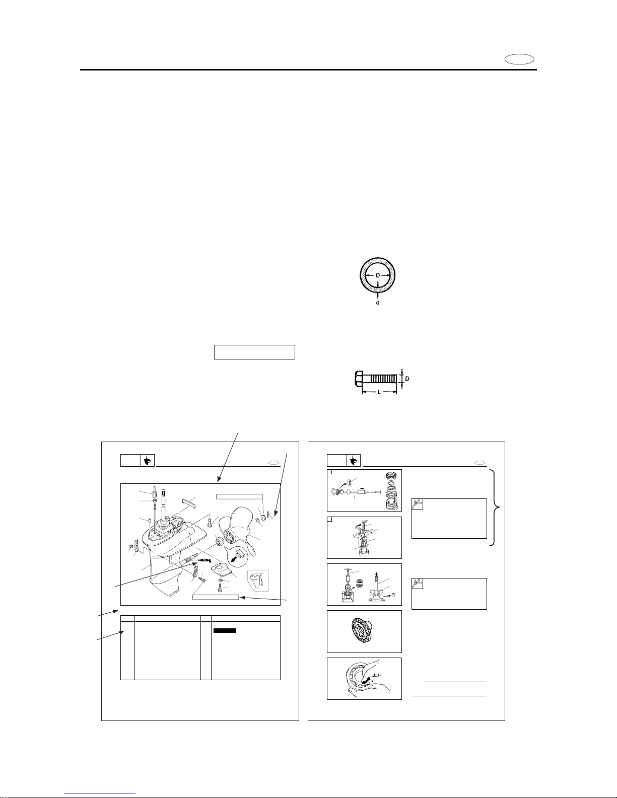
HOW TO USE THIS MANUAL
1 To help identify parts and clarify procedure steps, there are exploded diagrams at the
start of each removal and disassembly section.
2 Numbers are given in the order of the jobs in the exploded diagram. A circled number
indicates a disassembly step.
3 Symbols indicate parts to be lubricated or replaced (see “SYMBOLS”).
4 A job instruction chart accompanines the exploded daiagram, providing the order of
jobs, names of parts, notes in jobs, etc.
Example:
O-ring size 39.5 x 2.5 mm: inside diameter (D) x ring diameter (d)
5 Dimension figures and the number of parts are provided for fasteners that require a tight-
ening torque:
Example:
Bolt or screw size 10 x 25 mm (2) : M10(D) x 25 mm (L)
6 Jobs requiring more information (such as special tools and technical data) are described
sequentially.
E
LOWER UNIT
LOWR
LOWER UNIT
EXPLODED DIAGRAM
17 Nm (1.7 m•kg, 12 ft•lb)
5 Nm (0.5 m•kg, 3.6 ft•lb)
1
2
3
4
5
8
9
12
17
16
15
13
14
10
14
11
6
7
18
6-1
REMOVAL AND INSTALLATION CHART
Step
1
2
3
4
5
6
7
8
9
10
11
Q’ty
1
1
1
1
1
1
1
4
1
2
1
Service points
Follow the left ”Step” for removal.
Not reusable
Procedure/Part name
LOWER REMOVAL
Cotter pin
Propeller nut
Spacer
Propeller
Collar
Locknut
Adjusting nut
Bolt (lower case)
Lower unit
Dowel pins
Seal rubber
2. Remove:
9Oil seals
9Needle bearing
Propeller shaft housing ass’y disassembly
1. Remove:
9Reverse gear
9reverse gear shim (s)
9Ball bearing 1
A For USA and CANADA
B Except for USA and CANADA
E
PROPELLER SHAFT HOUSING ASS’Y
LOWR
1
2
4
3
5
1
2
3
1
6-10
Slide hammer set 2:
YB-06096
Stopper guide plate 3:
90890-06501
Bearing puller 4:
90890-06535
Stopper guide stand 5:
90890-06538
Slide hammer set 1:
YB-06096
Driver rod 2:
YB-06071/90890-06604
Needle bearing attachment 3:
YB-06081/90890-06616
SERVICE POINTS
Gears inspection
1. Inspect:
9Tooth
9Dog
Wear/Damage → Replace.
Bearings inspection
1. Inspect:
9Bearing
Pitting/Rumbling → Replace.
NOTE:
Turn the bearing by fingers and check the
bearing pitching
A
B
3
4
5
6
2
1
2

ES
D
F
COMMENT UTILISER CE
MANUEL
1 Pour vous aider à identifier les
composants et clarifier les différentes étapes des procédures, une
vue éclatée est illustrée au début de
chacune des procédures de dépose
et de démontage.
2 Les numéros indiqués dans la vue
éclatée sont donnés dans l’ordre
des opérations. Un numéro encerclé indique une étape de démontage.
3 Les symboles indiquent les compo-
sants à lubrifier ou à remplacer
(voir “SYMBOLES”).
4 Un tableau d’instructions accom-
pagne la vue éclatée de manière à
fournir la séquence des opérations,
le nom des composants, les remarques relatives aux opérations,
etc.
Exemple :
Dimension de joint torique
39,5 × 2,5 mm : diamètre intérieur
(D) ×diamètre extérieur (d)
5 Les dimensions et les numéros de
référence des composants sont
fournis pour les éléments fixations
nécessitant un couple de serrage
déterminé :
Exemple :
Dimension de boulon ou de vis
10 × 25 mm (2) : M10 (D) × 25
mm (L) (2 pièces)
6 Les opérations nécessitant des in-
formations plus détaillées (comme
des outils spéciaux et des spécifications techniques) sont décrites de
façon séquentielle.
LEITFADEN ZUR BENUTZUNG DER
ANLEITUNG
1 Zur Erkennung von Teilen und
zur Erläuterung von Arbeitsabläufen stehen vor jedem Abschnitt, in dem es um die Zerlegung und den Zusammenbau
von Teilen geht, Darstellungen
in aufgelösten Einzelteilen.
2 Die Reihenfolge der Arbeits-
schritte laut den Darstellungen
in Einzelteilen ist mit Zahlen angegeben. Eine umkreiste Zahl
zeigt eine Zerlegung an.
3 Zu schmierende oder auszu-
wechselnde Teile werden durch
Symbole angezeigt (siehe
„SYMBOLE“).
4 Eine Tabelle mit Anweisungen,
in der die Reihenfolge der Arbeitsschritte, die Bezeichnungen
der Teile, Anmerkungen zu den
Arbeitsschritten usw. erwähnt
werden, ist jeder Darstellung in
aufgelösten Einzelteilen hinzugefügt.
Beispiel:
O-Ring-Größe: 39,5 × 2,5 mm:
Innendurchmesser (D) × Ring
durchmesser (d)
5 Bei Befestigungsteilen, die mit
auf ein bestimmtes Moment angezogen werden müssen, sind
die Abmessungen und die Zahl
der erforderlichen Teile angegeben.
Beispiel:
Bolzen- oder Schraubengröße:
10 × 25 mm (2) : M10(D) × 25
mm (L) (2 Stück)
6 Arbeiten, die einer ausführliche-
ren Information bedürfen (z.B.
Spezialwerkzeug und technische
Angaben), werden nachstehend
beschrieben.
COMO USAR ESTE MANUAL
1 Para contribuir a identificar las
piezas y aclarar las operaciones correspondientes a los distintos procedimientos, se incluyen diagramas de despiece al principio de
cada sección de desmontaje y montaje.
2 Los números que figuran en el dia-
grama de despiece están en el orden en que se hacen los trabajos.
Un número rodeado por un círculo
indica una operación de desmontaje.
3 Los símbolos indican piezas que
hay que lubricar o sustituir (vea
“SIMBOLOS”).
4 El diagrama de despiece va acom-
pañado de una tabla de instrucciones de trabajo en la que figura el
orden de éstos, nombres de las piezas, notas sobre los trabajos, etc.
Ejemplo:
Tamaño de junta tórica
39,5 × 2,5 mm: Diámetro interior
(D) × anchura de la corona (d)
5 Los elementos de unión que re-
quieren pares de apriete van acompañados de las cifras de dimensiones y la cantidad de piezas.
Ejemplo:
Tamaño de perno o tornillo
10 × 25 mm (2) : M10(D)× 25 mm
(L) (2 piezas)
6 Los trabajos que requieran más in-
formación (como la relativa a herramientas especiales y datos técnicos) se describen en secuencia.
E
12
34
56
78
90
qw
er
ty
ui
op
as
df
GEN
INFO
A50001-1-4
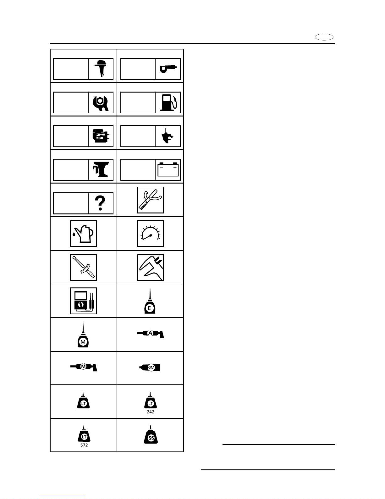
SYMBOLS
Symbols 1 to 9 are designed as thumbtabs to indicate the content of a chapter.
1 General information
2 Specifications
3 Periodic inspection and adjustment
4 Fuel system
5 Power unit
6 Lower unit
7 Bracket unit
8 Electrical system
9 Trouble-analysis
Symbols 0 to t indicate specific data:
0 Special tool
q Specified liquid
w Specified engine speed
e Specified torque
r Specified measurement
t Specified electrical value
[Resistance (Ω), Voltage (V), Electric current
(A)]
Symbol y to o in an exploded diagram
indicate the grade of lubricant and location
of the lubrication point:
y Apply Yamaha 4-stroke outboard motor oil
u Apply molybdenum disulfide oil
i Apply water resistant grease (Yamaha
grease A, Yamaha marine grease)
o Apply molybdenum disulfide grease
Symbols p to f in an exploded diagram
indicate the grade of sealing or locking
agent, and the location of the application
point:
p Apply Gasket Maker
®
a Apply LOCTITE®No. 271 (Red LOCTITE)
s Apply LOCTITE®No. 242 (Blue LOCTITE)
d Apply LOCTITE®No. 572
f Apply Silicon sealant
NOTE:
In this manual, the above symbols may not
be used in every case.
SPEC
INSP
ADJ
FUEL
POWR LOWR
BRKT ELEC
TRBL
ANLS
271

ES
D
F
SYMBOLES
Les symboles 1 à 9 sont représentés
sur les onglets et renseignent sur le
contenu des différents chapitres :
1 Informations générales
2 Spécifications
3 Inspection périodique et réglage
4 Circuit d’alimentation
5 Moteur
6 Boîtier d’hélice
7 Support
8 Circuit électrique
9 Dépannage
Les symboles 0 à t apportent certaines précisions :
0 Outil préconisé
q Liquide préconisé
w Régime moteur préconisé
e Couple spécifié
r Mesure spécifiée
t Valeur électrique spécifiée
[Résistance (Ω), tension (V), intensité
(A)]
Les symboles y à o des vues éclatées
donnent la qualité de lubrifiant à employer et les points de graissage :
y Huile pour moteur hors-bord 4 temps
Yamaha
u
Appliquez de la huile au bisulfure
de molybdène
i Graisse hydrofuge (graisse marine
Yamaha A, graisse marine Yamaha)
o Appliquez de la graisse au bisulfure de
molybdène
Les symboles p à f des vues éclatées
indiquent la qualité des agents d’étanchéité ou de blocage à employer ainsi
que les points d’application :
p Liquide d’étanchéité Gasket Maker(R)
a Agent bloquant LOCTITE(R) n° 271
(LOCTITE rouge)
s Agent bloquant LOCTITE(R) n° 242
(LOCTITE bleu)
d Agent bloquant LOCTITE(R) n° 572
f Produit d’étanchéité à base de silicone
N.B. :
Il est possible que certains des symboles ci-dessus ne soient pas utilisés le
présent manuel.
SYMBOLE
Die Symbole 1 bis 9 sind als Daumenindex gedacht, die den Inhalt
eines Kapitels anzeigen.
1 Allgemeine Informationen
2 Spezifikationen
3 Periodische Inspektion und Einstel-
lung
4 Kraftstoffanlage
5 Antriebseinheit
6 Unterwasserteil
7 Motoraufhängung
8 Elektrik
9 Störungssuche
Die Symbole 0 bis t weisen auf
spezifische Daten und Erfordernisse
hin:
0 Spezialwerkzeug
q Spezielle Flüssigkeit
w Spezielle Motordrehzahl
e Spezielles Anzugsmoment
r Spezielles Maß
t Spezieller elektrischer Wert
[Widerstand (Ω), Spannung (V),
Stromstärke (A)]
Die Symbole y bis o in einer Darstellung in aufgelösten Einzelteilen
weisen auf den Schmiermittelgrad
und Schmierstellen hin:
y Yamaha-Viertakt-Außenbordmotoröl
benutzen
u Molybden-Disulfid-Öl auftragen.
i Wasserbeständiges Fett (Yamaha-
Schmierfett A, Yamaha-Marinefett)
benutzen
o Molybden-Disulfid-Fett auftragen.
Die Symbole p bis f in einer Darstellung in aufgelösten Einzelteilen
weisen auf den Grad eines Dichtungs- oder Sicherungsmittels sowie auf die Anbringungsstelle hin:
p Gasketmaker®auftragen
a LOCTITE
®
Nr. 271 (rot) auftragen
s LOCTITE
®
Nr. 242 (blau) auftragen
d LOCTITE
®
Nr. 572 auftragen
f Silikondichtungsmittel auftragen
HINWEIS:
In diesem Handbuch können die
obenstehenden Symbole nicht in jedem Fall benutzt werden.
SIMBOLOS
Los símbolos 1 a 9 están concebidos
como pestañas para indicar el contenido de un capítulo.
1 Información general
2 Especificaciones
3 Inspección periódica y ajuste
4 Sistema de combustible
5 Grupo motor
6 Unidad inferior
7 Unidad de soporte
8 Sistema eléctrico
9 Localización de averías
Los símbolos 0 a t indican datos especificados:
0 Herramienta especial
q Líquido especificado
w Velocidad especificada del motor
e Pares especificados
r Medidas especificadas
t Valor eléctrico especificado
[Resistencia (Ω), tensión (V), corriente
eléctrica (A)]
Los símbolos y a o en un diagrama
de despiece indican el grado de lubricante y el sitio del punto de lubricación:
y Aplique aceite Yamaha de motor fuera
borda de 4 tiempos
u Aplicar aceite de bisulfuro de molibdeno
i Aplique grasa resistente al agua (grasa
Yamaha A, grasa marina Yamaha)
o Aplicar grasa de bisulfuro de molibdeno
Los símbolos p a f en un diagrama
de despiece indican el grado de agente
sellante o de bloqueo y el sitio del punto de aplicación:
p Aplique Gasket Maker
®
a Aplique LOCTITE®nº 271 (LOCTITE
rojo)
s Aplique LOCTITE
®
nº 242 (LOCTITE
azul)
d Aplique LOCTITE
®
nº 572
f Aplique sellante de silicona
NOTA:
En este manual, pueden no utilizarse
en todos los casos los símbolos anteriores.

E
TROUBLE-ANALYSYS
A30000-0
INDEX
FUEL SYSTEM
POWER UNIT
LOWER UNIT
BRACKET UNIT
ELECTRICAL SYSTEM
PERIODIC INSPECTION AND
ADJUSTMENT
SPECIFICATION
GENERAL INFORMATION
ES
D
F
INSPECCION
YAJUSTE
PERIODICOS
DIAGNOSTICO
DE PROBLEMAS
ESPECIFICACIONES
INFORMACION
GENERAL
SISTEMA DE
COMBUSTIBLE
MOTOR
UNIDAD DE
SOPORTE
SISTEMA
ELECTRICO
INSP
ADJ
TRBL
ANLS
SPEC
FUEL
POWR
LOWR
BRKT
ELEC
GEN
INFO
UNIDAD INFERIOR
9
3
2
1
4
5
6
7
8
ALLGEMEINE
ANGABEN
SPECIFICATIONS
INSPECTION
PERIODIQUE ET
REGLAGE
DEPANNAGE
TECHNISCHE
DATEN
REGELMÄSSIGE
WARTUNG UND EINSTELLUNGEN
CIRCUIT D’ALIMENTATION
KRAFTSTOFFANLAGE
MOTEUR
STROMVERSORGUNG
BOITIER D’HELICE
UNTERER TEIL
SUPPORT
HALTERUNGSRAHMEN
CIRCUIT
ELECTRIQUE
ELEKTROANLAGE
PROBLEMLÖSUNGEN
TABLE DES
MATIERES
INHALT
INDICE
INFORMATIONS
GENERALES

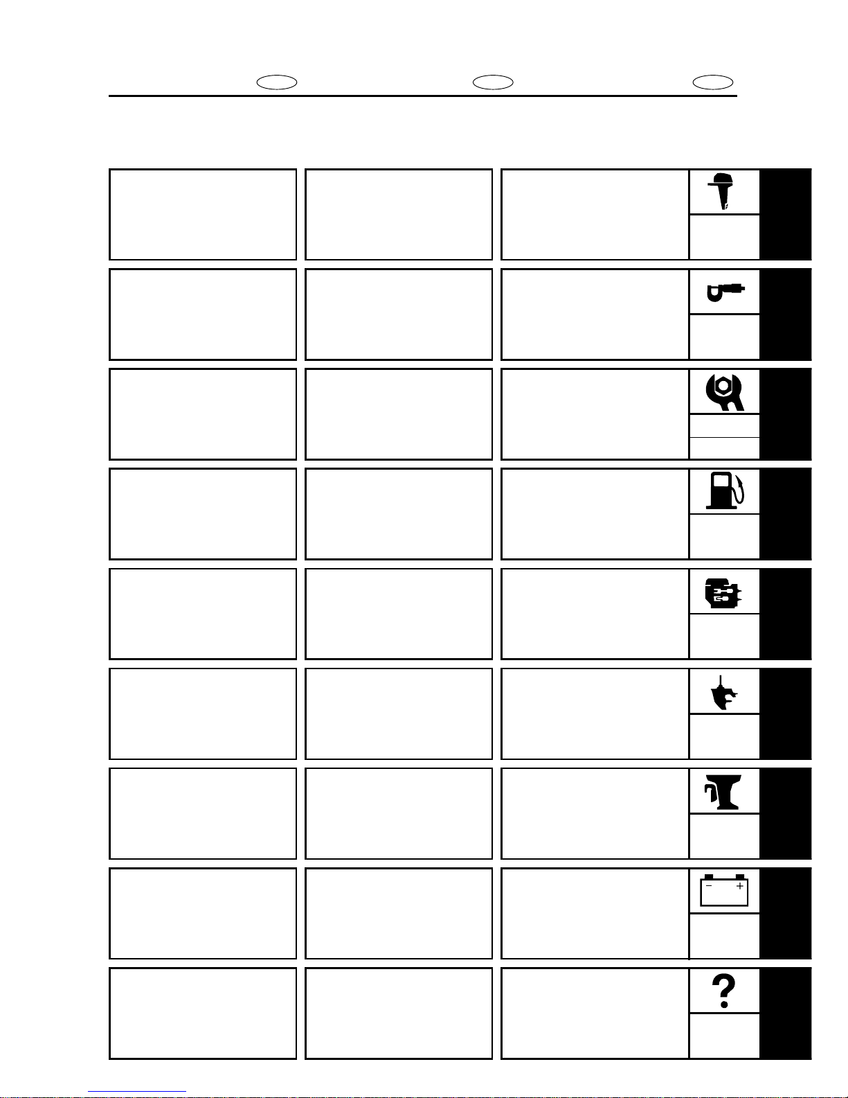
E
GEN
INFO
CHAPTER 1
GENERAL INFORMATION
IDENTIFICATION ...........................................................................................1-1
SERIAL NUMBER ....................................................................................1-1
STARTING SERIAL NUMBERS...............................................................1-1
SAFETY WHILE WORKING...........................................................................1-2
FIRE PREVENTION ..................................................................................1-2
VENTILATION ..........................................................................................1-2
SELF-PROTECTION .................................................................................1-2
OILS, GREASES AND SEALING FLUIDS ...............................................1-2
GOOD WORKING PRACTICES ...............................................................1-3
DISASSEMBLY AND ASSEMBLY...........................................................1-4
SPECIAL TOOLS............................................................................................1-5
MEASURING............................................................................................1-5
REMOVAL AND INSTALLATION.............................................................1-7
GENERAL TOOL............................................................................................1-9

ES
D
F
9
3
2
1
4
5
6
7
8
1
CHAPITRE 1
INFORMATIONS
GENERALES
IDENTIFICATION.....................................1-1
NUMERO DE SERIE...............................1-1
DEBUT DE NUMEROS DE SERIE........1-1
MESURES DE SECURITE........................1-2
CONTRE LES INCENDIES.....................1-2
AERATION...............................................1-2
PROTECTION..........................................1-2
HUILES, GRAISSES ET
LIQUIDES D’ETANCHEITE.................1-2
NOTES SUR L’OUTILLAGE ET
LES PIECES ..........................................1-3
DEMONTAGE ETREMONTAGE..........1-4
OUTILLAGE SPECIAL.............................1-5
MESURAGE.............................................1-5
DEPOSE ET INSTALLATION................1-7
OUTILLAGE GENERAL..........................1-9
KAPITEL 1
ALLGEMEINE
ANGABEN
KENNUMMERN .........................................1-1
SERIENNUMMER ..................................1-1
ANFANGSNUMMERN DER SERIE .......1-1
SICHERHEITSMASSNAHMEN..................1-2
BRANDSCHUTZ.....................................1-2
BELÜFTUNG ..........................................1-2
SELBSTSCHUTZ ....................................1-2
ÖLE, SCHMIERSTOFFE UND
DICHTUNGSMITTEL............................1-2
RICHTIGE
ARBEITSGEWOHNHEITEN .................1-3
DEMONTAGE UND MONTAGE ............1-4
SPEZIALWERKZEUGE................................1-5
MESSEN.................................................1-5
AUSBAU UND EINBAU.........................1-7
ALLGEMEINES WERKZEUG .....................1-9
CAPITULO 1
INFORMACION
GENERAL
IDENTIFICACION.....................................1-1
NUMERO DE SERIE...............................1-1
NUMEROS INICIALES DE SERIE........1-1
SEGURIDAD EN ELTRABAJO...............1-2
PREVENCION DE INCENDIOS.............1-2
VENTILACION........................................1-2
AUTOPROTECCION...............................1-2
ACEITES, GRASAS YLIQUIDOS
OBTURANTES ......................................1-2
PROCEDIMIENTOS DE TRABAJO
CORRECTOS.........................................1-3
DESMONTAJE YMONTAJE..................1-4
HERRAMIENTAS ESPECIALES.............1-5
MEDICION...............................................1-5
RETIRAD E INSTALACION..................1-7
HERRAMIENTADE USO GENERAL ....1-9
Model name
F15AMH
F15MSHX
66M
S: 001432~
F15MLHX L: 300964~
F15AEH
F15ESHX
66M
S: 200590~
F15ELHX L: 500755~
F15AE — 66M
S: 100302~
L: 400316~
F9.9CMH — 66N
S: 000128~
L: 300319~
F9.9CEH — 66N
S: 200101~
L: 500268~
F9.9CE — 66N
S: 100106~
L: 400121~
S: 000101~
FT9.9DMH — 66R L: 200101~
X: 500101~
FT9.9DEH — 66R
L: 300101~
X: 600101~
S: 100101~
FT9.9DE — 66R L: 400101~
X: 700101~
1-1
GEN
INFO
E
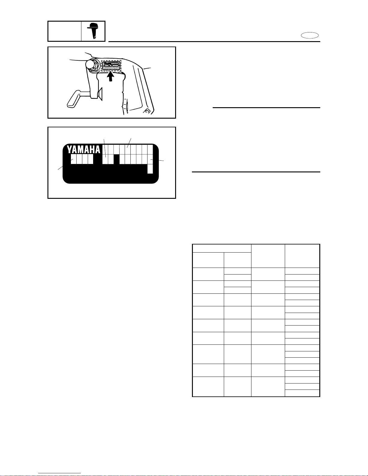
IDENTIFICATION
A60001-1
IDENTIFICATION
SERIAL NUMBER
The outboard motor's serial number is
stamped on a label which is attached to the
port side of the clamp bracket.
NOTE:
For USA model:
As an antitheft measure, a special label on
which the outboard motor’s serial number
is stamped is bonded to the port side of the
clamp bracket. The label is specially treated
so that peeling it off causes cracks across
the serial number.
1 Model name
2 Approved model code
3 Transom height
4 Serial number
Worldwide
USA/
CANADA
STARTING SERIAL NUMBERS
The starting serial number blocks are as follows:
Approved
model code
Starting
serial
number
YAMAHA MOTOR CO., LTD.
MADE IN JAPAN
PAYS D' ORIGINE JAPON
1
2
3
4
Modèle
66M
66M
66M
66N
66N
66N
66R
66R
66R
F15MSHX
F15MLHX
F15ESHX
F15ELHX
—
—
—
—
—
—
—
1-1
ES
D
F
GEN
INFO
IDENTIFICATION
KENNUMMERN
IDENTIFICACION
IDENTIFICATION
NUMERO DE SERIE
Le numéro de série du moteur est estampillé sur l’étiquette apposée du côté
bâbord du support de bridage.
N.B.:
Modèle pour les E.-U.
Le numéro de série du moteur figure
sur une étiquette spéciale antivol qui
est apposée au côté bâbord.
Cette étiquette est conçue de sorte
qu’elle se fendille à l’endroit du numéro de série quand on tente de
la décoller.
1 Nom du modèle
2 N° de modèle approuvé
3 Hauteur de barre d’arcasse
4 Numéro de série
DEBUT DE NUMEROS DE SERIE
Les blocs de début de numéros de série
sont les suivants:
IDENTIFICACION
NUMERO DE SERIE
El número de serie del motor fuera
borda aparece estampado en la etiqueta
fijada al lado de babor de la abrazadera
de sujeción.
NOTA:
Para el modelo para EE. UU.
Como medida antirrobo, al lado de babor del soporte de abrazadera hay fijada una etiqueta especial en la que aparece estampado el número de serie del
motor fuera de borda. La etiqueta se ha
sometido a un tratamiento especial de
forma que al arrancarla se agriete el
número de serie.
1 Nombre de modelo
2 N.° de modelo aprobado
3 Altura del peto de popa
4 Número de serie
NUMEROS INICIALES DE SERIE
Los bloques de números iniciales de
serie son los siguientes:
Monde
E.-U./
CANADA
N° de
modèle
DEBUT DE
N° approuvé
DE SERIE
KENNUMMERN
SERIENNUMMER
Die Seriennummer des Außenbordmotors befindet sich auf dem Aufkleber auf der Steuerbordseite der
Spannklemme.
HINWEIS:
Für USA-MODELLE
Zur Diebstahlsicherung ist ein spezielles Etikett mit der eingestanzten
Seriennummer des Außenbordmotors auf die Backbordseite geklebt.
Das Etikett ist spezialbehandelt, so
daß bei der Ablösung Risse an der
Seriennummer entstehen.
1 Modellbezeichnung
2 Zugelassene Modellnummer
3 Spiegelhöhe
4 Seriennummer
ANFANGSNUMMERN DER SERIE
Die Anfangsnummern der Serien
sind wie folgt:
F15
AMH
F15
AEH
F15
AE
F9.9
CMH
F9.9
CEH
F9.9
CE
FT9.9
DMH
FT9.9
DEH
FT9.9
DE
S: 001432~
L: 300964~
S: 200590~
L: 500755~
S: 100302~
L: 400316~
S:000128~
L:300319~
S:200101~
L:500268~
S:100106~
L:400121~
S:000101~
L:200101~
X:500101~
L:300101~
X:600101~
S:100101~
L:400101~
X:700101~
Modell
66M
66M
66M
66N
66N
66N
66R
66R
66R
F15MSHX
F15MLHX
F15ESHX
F15ELHX
—
—
—
—
—
—
—
Weilt
weit
USA/
KANADA
Zugela-
ssene
Anfangsnu
mmer der
Serie
F15
AMH
F15
AEH
F15
AE
F9.9
CMH
F9.9
CEH
F9.9
CE
FT9.9
DMH
FT9.9
DEH
FT9.9
DE
S: 001432~
L: 300964~
S: 200590~
L: 500755~
S: 100302~
L: 400316~
S:000128~
L:300319~
S:200101~
L:500268~
S:100106~
L:400121~
S:000101~
L:200101~
X:500101~
L:300101~
X:600101~
S:100101~
L:400101~
X:700101~
Modelo
66M
66M
66M
66N
66N
66N
66R
66R
66R
F15MSHX
F15MLHX
F15ESHX
F15ELHX
—
—
—
—
—
—
—
Todo los
países
EE.UU./
CANADA
N° de
modelo
Número de
serie
Aprobado
F15
AMH
F15
AEH
F15
AE
F9.9
CMH
F9.9
CEH
F9.9
CE
FT9.9
DMH
FT9.9
DEH
FT9.9
DE
S: 001432~
L: 300964~
S: 200590~
L: 500755~
S: 100302~
L: 400316~
S:000128~
L:300319~
S:200101~
L:500268~
S:100106~
L:400121~
S:000101~
L:200101~
X:500101~
L:300101~
X:600101~
S:100101~
L:400101~
X:700101~
1-2
GEN
INFO
E
SAFETY WHILE WORKING
SAFETY WHILE WORKING
The procedures given in this manual are
those recommended by Yamaha to be followed by Yamaha dealers and their
mechanics.
FIRE PREVENTION
Gasoline (petrol) is highly flammable.
Petroleum vapor is explosive if ignited.
Do not smoke while handling gasoline and
keep it away from heat, sparks and open
flames.
VENTILATION
Petroleum vapor is heavier than air and is
deadly if inhaled in large quantities. Engine
exhaust gases are harmful to breathe.
When test-running an engine indoors,
maintain good ventilation.
SELF-PROTECTION
Protect your eyes with suitable safety glasses or safety goggles, when grriding or when
doing any operation which may cause particles to fly off. Protect hands and feet by
wearing safety gloves or protective shoes if
appropriate to the work you are doing.
OILS, GREASES AND SEALING FLUIDS
Use only genuine Yamaha oils, greases and
sealing fluids or those recommended by
Yamaha.
YAMAHA
OIL

1-2
ES
D
F
GEN
INFO
MESURES DE SECURITE
SICHERHEITSMASSNAHMEN
SEGURIDAD EN ELTRABAJO
MESURES DE SECURITE
Les opérations décrites dans ce manuel
sont recommandées par Yamaha et doivent être suivies par les concessionnaires Yamaha et leurs mécaniciens.
CONTRE LES INCENDIES
L’essence est un produit très inflammable.
Les vapeurs d’essence sont explosives
lorsqu’elle sont enflammées. Ne pas
fumer lors de la manipulation d’essence.
La maintenir à l’écart de la chaleur,
des étincelles et des flammes.
AERATION
Les vapeurs d’essence sont plus
lourdes que l’air; inhalées en grande
quantité, elles sont mortelles. Les gaz
d’échappement du moteur sont
toxiques.
Lors d’essais de fonctionnement d’un
moteur en intérieur, s’assurer que l’endroit est bien aéré.
PROTECTION
Se protéger les yeux avec des lunettes
ou un masque de sécurité appropriés
lors de l’utilisation d’air comprimé ou
lors de toute opération durant laquelle
des particules risquent d’être projetées.
Si nécessaire, se protéger également
les mains et les pieds à l’aide gants et
des chaussures de protection.
HUILES, GRAISSES ET
LIQUIDES D’ETANCHEITE
N’utiliser que les huiles, graisses et liquides d’étanchéité Yamaha ou recommandés par Yamaha.
SICHERHEITSMASSNAHMEN
Die in diesem Handbuch angegebenen Maßnahmen sind von den
Yamaha-Händlern und ihren Mechanikern zu beachten.
BRANDSCHUTZ
Kraftstoff (Petroleum, Benzin) ist
leicht brennbar.
Benzindämpfe sind hochexplosiv.
Beim Umgang mit Kraftstoff nicht
rauchen sowie Funken und offenes
Feuer vermeiden.
BELÜFTUNG
Benzindämpfe sind schwerer als
Luft. Bei Einatmung großer Mengen
besteht Lebensgefahr. Motorabgase
sind gesundheitsschädlich und bei
längerem Einatmen lebensgefährlich. Beim Probelauf eines Motors
in geschlossenen Räumen für ausreichende Belüftung sorgen.
SELBSTSCHUTZ
Beim Arbeiten mit Druckluft, bei
Schleifarbeiten oder bei Spritzgefahr eine geeignete Sicherheitsoder Schutzbrille tragen. Füße
durch Sicherheitsschuhe schützen.
Wenn erforderlich, die Hände mit
Schutzhandschuhen schützen.
ÖLE, SCHMIERSTOFFE UND
DICHTUNGSMITTEL
Nur von Yamaha empfohlene Öle,
Schmierstoffe und Dichtungsmittel
verwenden.
SEGURIDAD EN EL
TRABAJO
Los procedimientos incluidos en este
manual son los que Yamaha recomienda a sus concesionarios y
mecánicos.
PREVENCION DE INCENDIOS
La gasolina (petróleo) es altamente inflamable.
El vapor de petróleo es explosivo si se
enciende.
No fume mientras manipula gasolina y
manténgala alejada del calor, chipas y
llamas.
VENTILACION
El vapor de petróleo es más pesado
que el aire y si se inhala en grandes
cantidades puede provocar asfixia. Los
gases de escape del motor son dañinos.
Cuando compruebe el funcionamiento
de un motor en un local cerrado, mantenga el lugar bien ventilado.
AUTOPROTECCION
Proteja sus ojos con gafas de seguridad
cuando utilice aire comprimido, cuando esmerile o cuando realice cualquier
operación que provoque el desprendimiento de partículas. Proteja sus manos y pies con guantes de seguridad o
zapatos fuertes apropiados para el trabajo a realizar.
ACEITES, GRASAS Y LIQUIDOS
OBTURANTES
Utilice siempre aceites, grasas y líquidos obturantes genuinos Yamaha, u
otros recomendados por Yamaha.
1-3
GEN
INFO
E
SAFETY WHILE WORKING
Under normal conditions of use, there
should be no hazards from the use of the
lubricants mentioned in this manual, but
safety is all-important, and by adopting
good safety practices, any risk is minimized.
A summary of the most important precautions is as follows:
1. While working, maintain good standards of personal and industrial
hygiene.
2. Clothing which has become contaminated with lubricants should be
changed as soon as practicable, and
laundered before further use.
3. Avoid skin contact with lubricants; do
not, for example, place a soiled wipingrag in your pocket.
4. Hands and any other part of the body
which have been in contact with lubricants or lubricant-contaminated clothing, should be thoroughly washed with
hot water and soap as soon as practicable.
5. To protect the skin, the application of a
suitable barrier cream to the hands
before working is recommended.
6. A supply of clean lint-free cloths should
be available for wiping purposes.
GOOD WORKING PRACTICES
1. The right tools
Use the recommended special tools to
protect parts from damage. Use the
right tool in the right manner — do not
improvise.
2. Tightening torque
Follow the tightening torque instructions. When tightening bolts, nuts and
screws, tighten the large sizes first, and
tighten inner-positioned fixings before
outer-positioned ones.

1-3
ES
D
F
GEN
INFO
MESURES DE SECURITE
SICHERHEITSMASSNAHMEN
SEGURIDAD EN ELTRABAJO
Dans des conditions normales d’utilisation, il ne devrait pas y avoir de dangers liés à l’utilisation des lubrifiants
spécifiés dans ce manuel. Il convient
cependant de prendre toutes les précautions de sécurité requises pour en
minimiser les risques.
Les principales précautions à prendre
peuvent se résumer de la façon suivante:
1. En travaillant, observez les conditions d’hygiène personnelle et industrielle qui s’imposent.
2. Les vêtements contaminés par des
lubrifiants doivent être changés le
plus rapidement possible et lessivés avant toute réutilisation.
3. Evitez le contact des lubrifiants
sur la peau; ainsi, ne mettez pas
en poche des chiffons souillés.
4. Si les mains ou toute autre partie
du corps ont été en contact avec
des lubrifiants ou des vêtements
contaminés de lubrifiant, lavez-les
dès que possible à l’eau chaude et
au savon.
5. Pour vous protéger la peau, nous
vous conseillons d’appliquer sur
les mains une crème écran appropriée avant de commencer à travailler.
6. Prévoyez toujours une réserve
suffisante de chiffons propres et
non pelucheux.
Unter normalen Betriebsbedingungen entstehen durch die Verwendung der in diesem Handbuch genannten Schmierstoffe keine Gefahren. Sicherheit ist jedoch oberstes
Gebot. Durch Beachtung der Sicherheitsmaßnahmen werden jegliche
Gefahren auf ein Minimum begrenzt.
Nachstehend folgt eine Übersicht
der wichtigsten Sicherheitsmaßnahmen:
1. Während der Arbeit immer für
saubere, gut sitzende Arbeitskleidung und einen sauberen
Arbeitsplatz sorgen.
2. Durch Schmiermittel verschmutzte Kleidung so bald
wie möglich wechseln und vor
derweiteren Benutzung gründlich reinigen.
3. Schmiermittel nicht mit der
Haut in Berührung bringen.
Keine schmutzigen Lappen in
die Tasche stekken.
4. Hände und andere Körperteile,
die in Berührung mit Schmiermitteln oder durch Schmiermittel verschmutzte Kleidung gekommen sind, so bald wie
möglich gründlich mit warmem
Wasser und Seife reinigen.
5. Zum Schutz der Haut wird vor
Arbeitsbeginn das Auftragen
einer geeigneten Schutzcreme
empfohlen.
6. Ein Vorrat an geeigneten Putztüchern oder saugfähigem Papier sollte stets vorhanden
sein.
En condiciones normales de uso, el
empleo de los lubricantes mencionados
en este manual no debe plantear ningún riesgo, pero la seguridad es un
tema de la máxima importancia, por lo
que la adopción de algunas medidas de
seguridad puede reducir los posibles
riesgos.
A continuación se incluye un resumen
de las precauciones más importantes:
1. Cuando trabaje, mantenga una higiene personal e industrial correcta.
2. La ropa contaminada con lubricante debe cambiarse tan pronto
como sea posible y ser lavada antes de volver a usarla.
3. Evite el contacto de la piel con los
lubricantes. Por ejemplo, no introduzca un trapo impregnado en el
bolsillo.
4. Las manos y cualquier otra parte
del cuerpo que haya estado en
contacto con lubricantes o ropa
contaminada por lubricantes deben lavarse minuciosamente con
agua caliente y jabón tan pronto
como sea posible.
5. Para proteger la piel, se recomienda aplicar una crema protectora
apropiada en las manos antes de
iniciar el trabajo.
6. Debe disponerse de paños limpios
que no dejan pelusa para fines de
limpieza.
NOTE SUR L’OUTILLAGE ET
LES PIECES
1. Outillage adéquat
Utilisez l’outillage spécial préconisé afin de protéger les pièces
contre tout dommage. Utilisez
l’outillage adéquat et de la façon
prescrite. N’improvisez en aucune
circonstance.
2. Couple de serrage
Respectez les couples de serrage
spécifiés. Lorsque vous serrez des
boulons, des écrous et des vis,
commencez par serrer ceux dont
le diamètre est le plus important
en allant du centre vers l’extérieur.
RICHTIGE ARBEITSGEWOHNHEITEN
1. Die richtigen Werkzeuge
Um Motorteile vor Beschädigung zu schützen, passendes
Werkzeug und empfohlenes
Spezialwerkzeug benutzen. Das
Werkzeug in der vorgeschriebenen Art und Weise benutzen
– nicht behelfsmäßig seinem
Zweck entfremden.
2. Anzugsdrehmoment
Die Anweisungen über die Anzugsdrehmomente beachten.
Beim Festziehen der Schrauben
und Muttern zuerst die größeren Schrauben anziehen. Danach die innenliegenden und
zuletzt die außenliegenden
Schrauben anziehen.
PROCEDIMIENTOS DE TRABAJO CORRECTOS
1. Las herramientas correctas
Utilice las herramientas especiales aconsejadas para evitar dañar
las piezas. Utilice la herramienta
correcta de la manera apropiada
— no improvise.
2. Par de apriete
Siga las instrucciones relacionadas al par de apriete. Cuando
apriete pernos, tuercas y tornillos,
apriete en primer lugar los de mayor tamaño, y apriete los situados
en la parte interior antes de apretar los situados en la parte exterior.
1-4
GEN
INFO
E
SAFETY WHILE WORKING
3. Non-reusable items
Always use new gaskets, packings, Orings, split-pins and circlips, etc., on
reassembly.
DISASSEMBLY AND ASSEMBLY
1. Clean parts with compressed air when
disassembling.
2. Oil the contact surfaces of moving parts
before assembly.
3. After assembly, check that moving parts
operate normally.
4. Install bearings with the manufacturer's
markings on the side exposed to view,
and liberally oil the bearings.
cC
Do not use compressed air to spin the bearings dry. This causes damage to the bearing surfaces.
5. When installing oil seals, apply a light
coating of water-resistant grease to the
outside diameter.

1-4
ES
D
F
GEN
INFO
MESURES DE SECURITE
SICHERHEITSMASSNAHMEN
SEGURIDAD EN ELTRABAJO
3. Pièces à usage unique
Lors du remontage, toujours utiliser des joints, garnitures, joints
toriques, goupilles fendues et circlips neufs.
DEMONTAGE ETREMONTAGE
1. Lors du démontage, nettoyer les
pièces à l’air comprimé.
2. Lors du montage, huiler les surfaces de contact des pièces mobiles.
3. Après le montage, vérifier que
toutes les pièces mobiles fonctionnent normalement.
4. Monter les roulements avec la
marque du fabricant tournée vers
l’extérieur et les huiler généreusement.
fF
N’utilisez pas d’air comprimé pour
sécher les roulements. Vous risquez
sinon d’endommager les surfaces des
roulements.
5. Lors du montage des bagues
d’étanchéité, appliquer une légère
couche de graisse hydrofuge sur
le diamètre extérieur.
3. Nicht wiederverwendbare Teile
Beim Wiedereinbau stets neue
Dichtungen, O-Ringe, Splinte,
Sicherungsringe usw. verwenden.
DEMONTAGE UND MONTAGE
1. Während des Ausbaus Teile mit
Druckluft reinigen.
2. Kontaktflächen beweglicher
Teile beim Einbau fetten.
3. Nach der Montage bewegliche
Teile auf einwandfreie Funktion
prüfen.
4. Lager so einsetzen, daß die
Herstellerkennzeichen sichtbar
sind. Lager ausreichend fetten.
dD
Niemals Druckluft zum Trocknen
der Lager benutzen, weil dadurch
die Oberfläche der Lager beschädigt wird.
5. Beim Einbau der Öldichtungen
diese leicht mit einem wasserbeständigen Fett einreiben.
3. Elementos no reutilizables
Utilice siempre juntas, guarniciones, juntas toroidales, pasadores
hendidos y retenedores nuevos
cuando vuelva a montar los componentes.
DESMONTAJE YMONTAJE
1. Limpie las piezas con aire comprimido al desmontarlas.
2. Engrase las superficies de contacto de las piezas móviles al montarlas.
3. Tras el montaje, compruebe que
las partes móviles funcionan con
normalidad.
4. Instale los cojinetes con las marcas del fabricante encaradas hacia
el lado que queda expuesto a la
vista, y engráselos abundantemente.
bB
No se debe utilizar aire comprimido
para secar los cojinetes, ya que se
podrán dañar sus superficies.
5. Cuando instale juntas de aceite,
aplique una capa de grasa hidrófuga en la circunferencia exterior.
1-5
GEN
INFO
E
SPECIAL TOOLS
1
23
45
67
89
0
a
b
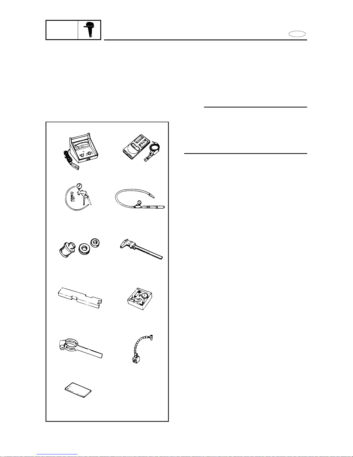
SPECIAL TOOLS
The use of correct special tools recommended by Yamaha will aid the work and
enable accurate assembly and tune-up.
Improvising and using improper tools can
damage the equipment.
NOTE:
9For U.S.A. and Canada, use part numbers
starting with “J-”, “YB-”, “
YM-
” “YU-” or
“YW-”.
9For others, use part numbers starting with
“90890-”.
MEASURING
1. Tachometer
a P/N. YU-08036-A
b 90890-06760
2. Mity vac
P/N. YB-35956
90890-06756
3. Leakage tester
P/N. YB-03595
90890-06762
4. Pinion height gauge
P/N. YB-34232
N.A.
5. Digital caliper
P/N. N.A.
90890-06704
6. Shimming plate
P/N. N.A.
90890-06701
7. Dial gauge set
P/N. YU-03097
90890-01252
8. Backlash indicator
P/N. YB-06265
90890-06706
9. Magneto base
P/N. YU-34481
90890-06705
10. Base plate
P/N. YB-07003
90890-07003
 Loading...