

Page 1
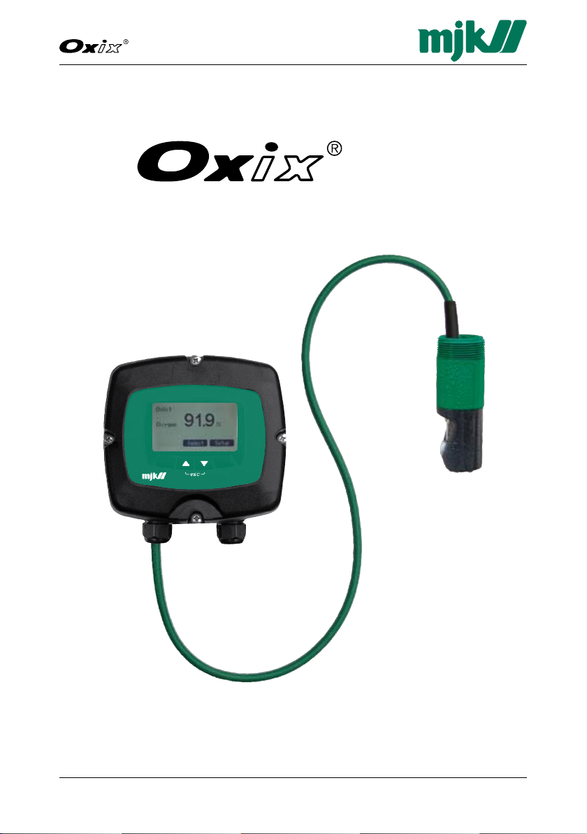
Dissolved Oxygen Transmitter
Dissolved Oxygen Transmitter
Installation and User Manual
1GB Oxix Manual 080915
FW: 841013-009, 846001-002, 841513-009
Page 2

2GB Oxix Manual 080915
FW: 841013-009, 846001-002, 841513-009
Dissolved Oxygen Transmitter
CE CERTIFICATE OF CONFORMITY
This product complies with the requirements concerning electromagnetic compatibility (EMC)
stipulated in Council directive no. 89/336/EEC of 3rd may 1989, alteret at directive no. 92/31/
EEC, on the approximation of the laws of the member states relating to electromagnetic compatibility.
CE approvals
We declare that the Oxix
®
transmitter complies with the values stipulated in EN-61010-1 and EN
61326-1.
Ex approval
The Oxix
®
transmitter is approved for mounting in explosive amospheres: Ex II G3.
Page 3

3
Dissolved Oxygen Transmitter
GB Oxix Manual 080915
FW: 841013-009, 846001-002, 841513-009
Table of Contents
1. Introduction 7
About this Manual . . . . . . . . . . . . . . . . . . . . . . . . . . . . . . . . . . . . . . . . . . . . . . . . . . . . . . .8
Operating Principles . . . . . . . . . . . . . . . . . . . . . . . . . . . . . . . . . . . . . . . . . . . . . . . . . . . .10
Features . . . . . . . . . . . . . . . . . . . . . . . . . . . . . . . . . . . . . . . . . . . . . . . . . . . . . . . . . . . . . .11
2. Safety, Repair and Product Identification 13
Safety Instructions . . . . . . . . . . . . . . . . . . . . . . . . . . . . . . . . . . . . . . . . . . . . . . . . . . . . .13
Physical Mounting . . . . . . . . . . . . . . . . . . . . . . . . . . . . . . . . . . . . . . . . . . . . . . . . . . . . . .13
Repair ................................................................13
Product Identification . . . . . . . . . . . . . . . . . . . . . . . . . . . . . . . . . . . . . . . . . . . . . . . . . . .13
3. Specifications and Order Numbers 15
Specifications ..........................................................15
Order Numbers .........................................................17
4. Sensor Installation 19
Physical Sensor Installation . . . . . . . . . . . . . . . . . . . . . . . . . . . . . . . . . . . . . . . . . . . . . .20
Preparation ...........................................................20
Positioning the Sensor . . . . . . . . . . . . . . . . . . . . . . . . . . . . . . . . . . . . . . . . . . . . . . . . . .20
5. Sensor Calibration 21
Zero-point Calibration Check . . . . . . . . . . . . . . . . . . . . . . . . . . . . . . . . . . . . . . . . . . . . .21
2-point Calibration . . . . . . . . . . . . . . . . . . . . . . . . . . . . . . . . . . . . . . . . . . . . . . . . . . . . .21
6. Converter 23
Electrical Mounting .....................................................23
Power Supply .........................................................24
Display Connector . . . . . . . . . . . . . . . . . . . . . . . . . . . . . . . . . . . . . . . . . . . . . . . . . . . . .24
Changing the Power Supply Voltage 230/115 V AC . . . . . . . . . . . . . . . . . . . . . . . . . . . .25
Analogue Output . . . . . . . . . . . . . . . . . . . . . . . . . . . . . . . . . . . . . . . . . . . . . . . . . . . . . .27
Digital Input . . . . . . . . . . . . . . . . . . . . . . . . . . . . . . . . . . . . . . . . . . . . . . . . . . . . . . . . . .28
Converter Terminals . . . . . . . . . . . . . . . . . . . . . . . . . . . . . . . . . . . . . . . . . . . . . . . . . . . .29
Sensor and Mounting Kit / Connection Board Terminals .........................30
7. System Configuration Examples 31
Magflux® with Blind Lid and Oxix® with Display Unit ...........................32
Wiring Schematic #1 . . . . . . . . . . . . . . . . . . . . . . . . . . . . . . . . . . . . . . . . . . . . . . . . . . .33
®
SuSix
with Blind Lid, Magflux® with Blind Lid and a Remote Display .............34
Wiring Schematic #2 . . . . . . . . . . . . . . . . . . . . . . . . . . . . . . . . . . . . . . . . . . . . . . . . . . .35
Page 4

4GB Oxix Manual 080915
FW: 841013-009, 846001-002, 841513-009
Dissolved Oxygen Transmitter
8. Startup 37
Initial Checks before Power-up ............................................37
Initial Power-up ........................................................37
Initial Measurement. . . . . . . . . . . . . . . . . . . . . . . . . . . . . . . . . . . . . . . . . . . . . . . . . . . . .37
Language Selection . . . . . . . . . . . . . . . . . . . . . . . . . . . . . . . . . . . . . . . . . . . . . . . . . . . .37
Display Read-out, one connected unit ......................................38
Display Read-out, several connected units ...................................39
Display Keys ..........................................................39
9. Oxix® Menus 41
Converter Overview Menu ................................................41
Specify Main Screen . . . . . . . . . . . . . . . . . . . . . . . . . . . . . . . . . . . . . . . . . . . . . . . . . . . .42
Datalogger ...........................................................44
Graph Display .........................................................46
Password . . . . . . . . . . . . . . . . . . . . . . . . . . . . . . . . . . . . . . . . . . . . . . . . . . . . . . . . . . . . .47
Sensor Name .........................................................49
Converter Setup ........................................................51
Averaging ............................................................52
Units ...............................................................52
mA Output ...........................................................53
Cleaning .............................................................54
High alarm . . . . . . . . . . . . . . . . . . . . . . . . . . . . . . . . . . . . . . . . . . . . . . . . . . . . . . . . . . .56
Low alarm . . . . . . . . . . . . . . . . . . . . . . . . . . . . . . . . . . . . . . . . . . . . . . . . . . . . . . . . . . .57
Sensor error ..........................................................58
Status . . . . . . . . . . . . . . . . . . . . . . . . . . . . . . . . . . . . . . . . . . . . . . . . . . . . . . . . . . . . . .59
Factory settings . . . . . . . . . . . . . . . . . . . . . . . . . . . . . . . . . . . . . . . . . . . . . . . . . . . . . . .60
Service Menu - Digest . . . . . . . . . . . . . . . . . . . . . . . . . . . . . . . . . . . . . . . . . . . . . . . . . .61
Service Menu - Detailed . . . . . . . . . . . . . . . . . . . . . . . . . . . . . . . . . . . . . . . . . . . . . . . . .62
Display Setup ..........................................................72
Language ............................................................73
Set clock . . . . . . . . . . . . . . . . . . . . . . . . . . . . . . . . . . . . . . . . . . . . . . . . . . . . . . . . . . . .74
Modbus . . . . . . . . . . . . . . . . . . . . . . . . . . . . . . . . . . . . . . . . . . . . . . . . . . . . . . . . . . . . .75
Factory settings . . . . . . . . . . . . . . . . . . . . . . . . . . . . . . . . . . . . . . . . . . . . . . . . . . . . . . .77
Display SW version .....................................................77
10. Mechanical Dimensions 79
Sensor ..............................................................79
Converter and Display Unit ...............................................80
Immersion Fitting . . . . . . . . . . . . . . . . . . . . . . . . . . . . . . . . . . . . . . . . . . . . . . . . . . . . . .81
11. Maintenance 83
Cleaning the sensor .....................................................83
Cleaning the converter display . . . . . . . . . . . . . . . . . . . . . . . . . . . . . . . . . . . . . . . . . . . .83
Functional Tests ........................................................83
Service Contract . . . . . . . . . . . . . . . . . . . . . . . . . . . . . . . . . . . . . . . . . . . . . . . . . . . . . . .83
Page 5

5
Dissolved Oxygen Transmitter
GB Oxix Manual 080915
FW: 841013-009, 846001-002, 841513-009
Appendix A. Pop-up and Error Messages 85
Appendix B. MJK-Field Link Software 89
Important Notes! ......................................................89
A. Connect a PC to the Oxix
B. Save Log Data . . . . . . . . . . . . . . . . . . . . . . . . . . . . . . . . . . . . . . . . . . . . . . . . . . . . .91
C. Upgrade Display Firmware . . . . . . . . . . . . . . . . . . . . . . . . . . . . . . . . . . . . . . . . . . . .91
D. Upgrade Converter Firmware . . . . . . . . . . . . . . . . . . . . . . . . . . . . . . . . . . . . . . . . . .93
E. Install/Add Languages ................................................94
®
............................................89
Appendix C. Front Panel Cut-out Drawing 95
Appendix D. Log Files 97
Appendix E. Input/Output Connections 101
Main Menu Overview 102
Converter Setup Menu Overview 106
Service Menu Overview 114
Display Setup Menu Overview 120
Index Index-1
Page 6

6GB Oxix Manual 080915
FW: 841013-009, 846001-002, 841513-009
Dissolved Oxygen Transmitter
This page intentionally left blank.
Page 7

7
Dissolved Oxygen Transmitter
GB Oxix Manual 080915
FW: 841013-009, 846001-002, 841513-009
1. Introduction
Thank you for choosing the MJK Oxix® Dissolved Oxygen Transmitter. We
have done our utmost to design and manufacture a quality transmitter that
satisfies your requirements:
High performance optical sensor•
No calibration•
No spareparts needed in sensor's 10 year lifetime•
Air or water jet cleaning system is standard•
Measurements not affected by sunlight or dry environment•
Large, easy-to-read display with trend curve capability•
Multiple languages•
Built-in datalogger•
No moving parts, oxygen consumption or risk of poisoning•
Mounting accessories • (optional)
The Oxix
ever, read this manual first to get familiar with the Oxix® transmitter and all its
features.
The equipment must be handled and operated as instructed by the manufacturer, MJK Automation A/S to ensure stable operation and accurate measurements.
You can always contact your local representative or the MJK hot lines for
advice and guidance:
®
transmitter is easy to install, calibrate and put into service. How-
Europe• Tel.: +45 45 56 06 56 E-mail: mjk@mjk.com
Denmark• Tel.: +45 45 56 06 56 E-mail: mjk@mjk.dk
Norway• Tel.: +47 69 20 60 70 E-mail: mjk@mjk.no
Sweden• Tel.: +46 53 31 77 50 E-mail: kontoret@mjk.se
Holland• Tel.: +31 251 672171 E-mail: mjknl@mjk.com
USA• Tel.: +1 847 482 8655 E-mail: mjkusa@mjk.com
Australia• Tel.: +61 3 9758 8533 E-mail: ns@mjk.com
Visit our web sites at www.oxix.dk and www.mjk.com to learn more about
MJK Automation, our other products and the people behind them.
®
Oxix
is a registered trademark of MJK Automation A/S, Denmark.
Page 8

8GB Oxix Manual 080915
FW: 841013-009, 846001-002, 841513-009
Dissolved Oxygen Transmitter
About this Manual
This manual is divided into one table of contents, eleven chapters, five appendices, four continuous menu overview flow charts and one index.
1. Introduction
Contains a presentation of the Oxix
structure of this manual, the operating principles and the top features.
2. Safety, Repair and Product Identification
Provide answers to issues regarding safety, mounting, repair,
restrictions and product identification.
3. Specifications and Order Numbers
The system specs and order numbers are listed for quick access.
4. Transmitter Installation
Contains installation guidelines for positioning of the transmitter in liquids,
distances to walls and other solid faces, and installation in tubes.
5. Sensor Calibration
The Oxix
®
sensor is factory calibrated and requires no re-calibration.
6. Converter
Describes the physical specifications and installation rules for the convert-
er such as power supply, in- and outputs, sensor/converter/
display configurations, etc.
7. System Configuration Examples
Illustrate how Oxix
®
Dissolved Oxygen Transmitter can be interconnected
with for example MJK MagFlux® flow meters in real-life scenarios.
8. Startup
Describes important checks and basic settings to get started including the
display and keyboard user interface.
9. Oxix
®
Menus
Contains a comprehensive description of the Oxix
utilities.
10. Mechanical Dimensions
Lists the Oxix
®
Dissolved Oxygen Transmitter dimensions.
11. Maintenance
Contains procedures for cleaning the sensor and the display.
®
Dissolved Oxygen Transmitter, the
®
menus, options and
Page 9

9
Dissolved Oxygen Transmitter
GB Oxix Manual 080915
FW: 841013-009, 846001-002, 841513-009
Appendix A. Pop-up Events / Error Messages
Lists possible pop-up messages, explains their meaning and offer
solutions to error conditions.
Appendix B. MJK-Field Link Software Upgrade
Describes in detail how to utilise the unique and intuitive MJK-Field Link
software program to upload new display and converter firmware
versions.
Appendix C. Front Panel Cut-out Drawing
A 1:1 scale drawing of the front panel outline and cut-out area for installa-
tion and mounting purposes.
Appendix D. Log Files
An example log file illustrates the format and explains the entries.
Appendix E. Digital Input/Output Connections
Illustrates how the digital in- and outputs can be interconnected.
* * * * *
Main Menu Overview
A continuous presentation of the top level menu structure.
Converter Setup Menu Overview
A continuous presentation of the converter setup menu structure.
Service Menu Overview
A continuous presentation of the service menu structure.
Display Setup Menu Overview
A continuous presentation of the display configuration menu structure.
Page 10

10GB Oxix Manual 080915
FW: 841013-009, 846001-002, 841513-009
Dissolved Oxygen Transmitter
Operating Principles
The MJK Oxix® Dissolved Oxygen Transmitter is designed for measuring the
oxygen contents in open tanks exposed to sunlight, wells and closed containers.
The Oxix® sensor function is based on the fluorescence principle and does
not consume oxygen like membrane-type sensors. It is rugged and designed
to handle tough applications.
Light pulses with a wavelength of 475 nm are transmitted to a ruthenium
compound immobilized in a sol-gel matrix.
The ruthenium absorbs the light energy by changing the outer electron’s energy level. The unstable electron then collapses and returns back to its original
energy state and at the same time emits the surplus energy as a photon with
a wavelength of 600 nm. This process is also refered to as fluorescing.
When the intensity of the transmitted light pulses is tightly controlled, the
amount of fluorescing is predictable and repeatable.
If free oxygen molecules are present, the photon energy is absorbed by the
oxygen molecules without any light emission, and the amount of fluorescing is
consequently reduced (also refered to as fluorescence quenching).
It is therefore possible to determine the amount of dissolved oxygen by measuring the amount of fluorescence quenching (light intensity).
Page 11
11
Dissolved Oxygen Transmitter
GB Oxix Manual 080915
FW: 841013-009, 846001-002, 841513-009
ll
RS485
RS485
RS485
Max. 1000 m
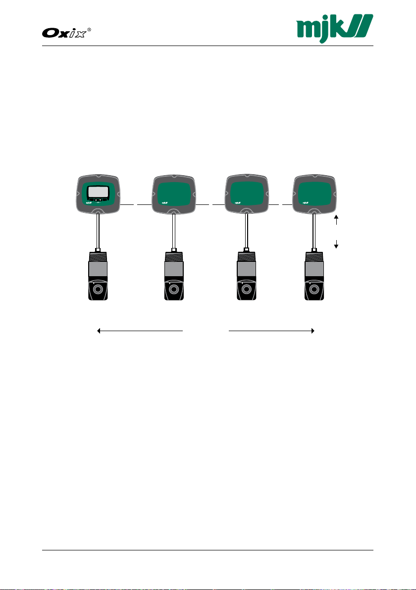
1 pc. Oxix Converter
with display
(
206505
)
3 pcs. Oxix without display (206508)
4 pcs. Oxix sensors (206510)
ll ll
300 m
Max.
Features
Flexible Installation
MJK’s modular design allows up to 300 meters (950ft.) between the sensor
and the converter, and the Display Unit can be mounted up to 1000 m
(3000 ft.) from the signal converter with ordinary twisted wires.
One Display Unit can control up to four MagFlux® flow meters, SuSix® transmitters and/or Oxix® transmitters for greater economy, space savings and an
improved overview of the multiple measurement values.
Simple to Operate
The Oxix® Display Unit has a mobile phone-like menu structure and can display text in several selectable languages.
PC Connection
®
Oxix
allows downloading setup configurations, uploading new instrument
software updates and display customization. The onboard data logger captures 20.000 readings which are displayed as an electronic graph and can be
retrieved as a CSV file on a PC. This connectivity is achieved with a common
USB port and the free MJK Field Link software.
Page 12

12GB Oxix Manual 080915
FW: 841013-009, 846001-002, 841513-009
Dissolved Oxygen Transmitter
Flexible In- and Outputs
The Oxix® Transmitter has one 4-20 mA analogue output, two digital outputs
for alarms or control, and one digital input for resetting alarms, batches, etc.
User-definable Text
Up to five lines of text and readings can be configured by the user. The
graphic display is automatically adjusted to show the largest characters possible. Alarms can be displayed as pop-up alarms until they are reset.
Modbus® Communication
The Display Unit uses the Modbus® RTU communication protocol to connect to the Oxix® Transmitter. The Transmitter can in turn connect to SCADA
systems with its Modbus® communication protocol.
Page 13

13
Dissolved Oxygen Transmitter
GB Oxix Manual 080915
FW: 841013-009, 846001-002, 841513-009
2. Safety, Repair and Product Identification
Safety Instructions
Read this manual carefully.•
Pay attention to the environment on the installation site.•
Wear necessary protective equipment and follow all current safety regula-•
tions.
®
Oxix•
can invoke a start signal for dangerous machinery. Always ensure
that connected machinery and other equipment are effectively put out
of service (that is to remove the main fuses and lock main and security
switches in off-position) before commencing configuration, fault finding,
servicing, maintenance work, etc.
• WARNING: There is a risk of lethal, electrical shock from the "Mains sup-
ply" terminals "N" and "L". Be careful not to touch these terminals when
the Oxix
WARNING:• Incorrect installation or use can lead to body injury and/or
material damage!
Physical Mounting
The Oxix® converter/display unit must not be mounted in explosion hazardous areas!
Oxix® may only be installed and commissioned by authorized MJK personnel,
and all national and local regulations must be complied with.
®
front cover is removed.
Repair
Repair must only be made by authorized MJK personnel or by a service representative approved by MJK.
Product Identification
A delivery will usually consist of an Oxix® sensor and an Oxix® converter with
or without a display unit.
Check that the item(s) delivered corresponds to the ordered item(s). The part
number is printed on an identification label stuck on the converter shipping
box and on a label on the converter itself.
Page 14

14GB Oxix Manual 080915
FW: 841013-009, 846001-002, 841513-009
Dissolved Oxygen Transmitter
This page intentionally left blank.
Page 15
15
Dissolved Oxygen Transmitter
GB Oxix Manual 080915
FW: 841013-009, 846001-002, 841513-009
3. Specifications and Order Numbers
Specifications
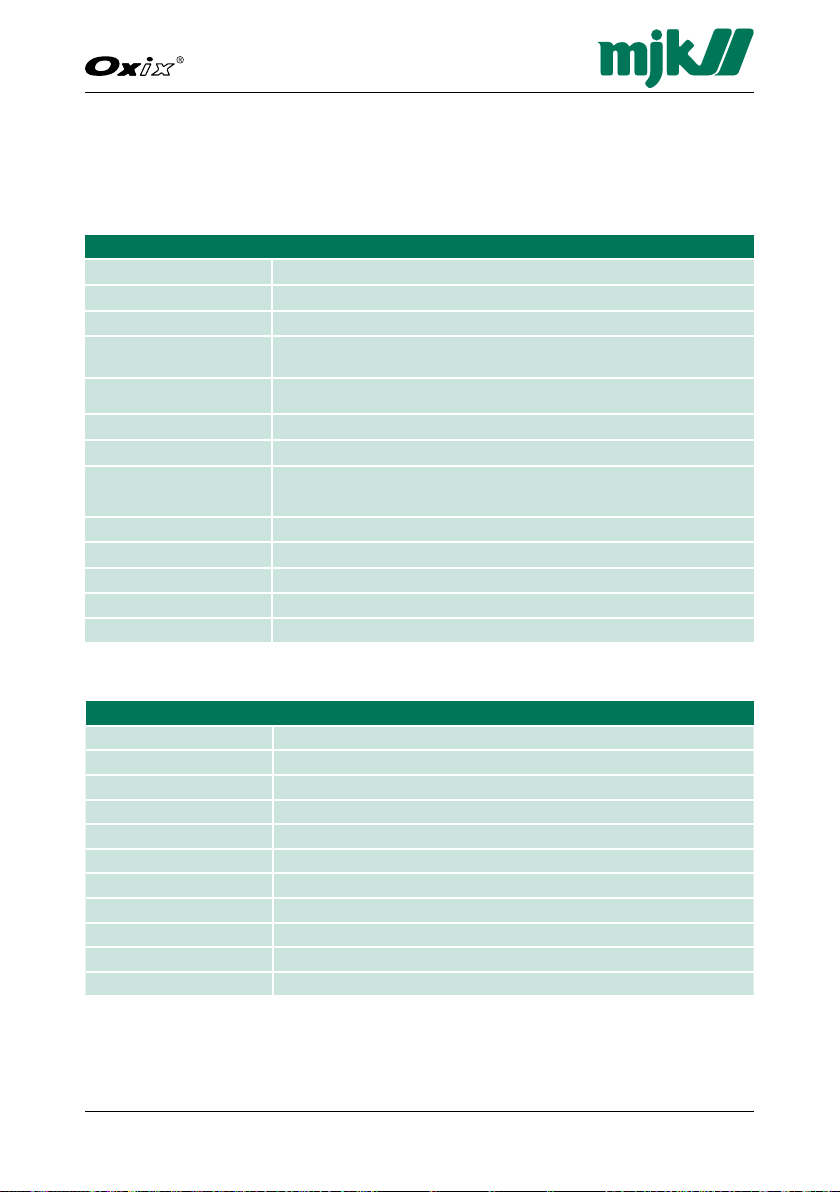
Oxix® Transmitter
Accuracy +/- 0,1% of reading
Measuring input RS 485
Analog output One active 4 - 20 mA, galvanically isolated (max. load 800 W)
Digital outputs
Digital inputs
Communication MODBUS
Interface RS 485 for connection to Display Unit or PLC
Power supply 10 - 30 V DC, or 24 V AC, 50 / 60 Hz ± 10 % or
Power consumption Max. 10 W
Cabinet material Polycarbonate, glass reinforced
Enclosure rating IP 67, NEMA 6
Temperature range - 20 … 60 °C
Weight 1,1 kg
One voltage-free electromechanical relay (max. 50 V DC / 1 A)
One optically isolated MOSFET relay (max. 50 VAC / V DC / 120 mA)
One, max. 30 V DC, < 5 V DC = 0(low), > 10 V DC = 1(high),
pulse length > 100 ms
®
RTU-mode, 9600 baud, 2-wire RS 485, slave-mode
115 V AC, 50 / 60 Hz ± 10 % or
230 V AC, 50 / 60 Hz ± 10 %
Display Unit
Enclosure rating Dust and waterproof IP 67, NEMA 6 (when mounted on converter)
Housing material Polycarbonate, glass reinforced
Protection lid Transparent polycarbonate
Display White backlit LCD-display (64 x 128 pixels) with softkeys
Indication Indication measurement, configuration and graph
Clock Real-time clock with built-in battery backup
Communication MODBUS
Interface RS 485
Memory 256 Kb Flash memory, 20.000 entries with date, time and value
Interface USB 1,1 type mini B, Female
Temperature range - 20 … 60 °C
®
RTU-mode, 9600 baud, 2-wire RS 485, master-mode
Page 16

16GB Oxix Manual 080915
FW: 841013-009, 846001-002, 841513-009
Dissolved Oxygen Transmitter
Oxix® Sensor
Dissolved oxygen saturated
Measurement principle Optical, near infra-red fluorescence (l
Sensor check Automatic self-diagnostics
Pressure 6 bar (100 psi)
Materials Boby and Head: PU, PVC, silicone, epoxy and stainless steel 316 SS
Cleaning system Built-in air or water jet
Cable 4 x 0,326 mm
Cable length 10 m (33 ft.), can be extended up to 600 mm
Response time t
Flow velocity No flow required
Power supply 12 V DC (10 -16 V DC), approx. 10 mA
Output RS 485, 9600 baud, 2-wire
Accuracy Better than 1% of actual reading (0,02 mg/l)
Resolution Better than 0,02 mg/l
Temperature range 0 - 60 ºC
Temperature compensation 0 - 50 ºC
Enclosure rating IP 68 to IEC 529 (10 m), NEMA 6
Dimensions 50 x 130 mm (diameter x length)
Mounting
Weight 0,77 kg (1.7 lbs)
0 - 30.0 mg/l or ppm (parts per million)
0 - 120 %
= 475 nm, I
in
Optical lens: Sapphire
O-ring: Viton
Cable: PUR
2
, shielded, outer diameter Ø 5.0 mm (22 AWG)
less than 1 second, t95 less than 60 second
90
1,5 inch NPT thread
0,25 inch NPT thread for jet spray cleaning tube
= 600 nm)
out
Page 17

17
Dissolved Oxygen Transmitter
GB Oxix Manual 080915
FW: 841013-009, 846001-002, 841513-009
Order Numbers
Oxix® Converters
®
206304 Oxix
206305 Oxix
206306 Oxix
206307 Oxix
206308 Oxix
206309 Oxix
Oxix® Sensor
206510 Oxix
Converter w/ display, 10 - 30 V DC
®
Converter w/ display, 230 / 115 V AC
®
Converter w/ display, 24 V AC
®
Converter without display, 10 - 30 V DC
®
Converter without display, 230 / 115 V AC
®
Converter without display, 24 V AC
®
Sensor
Accessories for Oxix
155230 Oxix
155236 Oxix
®
Sensors
®
Insertion adapter, 1½" NPT inner thread -> 2" RG outer thread
®
Immersion fitting
691120 Cable for Oxix
- 1½" NPT to 1¼" RG Adapter
®
sensor (PUR)
Page 18

18GB Oxix Manual 080915
FW: 841013-009, 846001-002, 841513-009
Dissolved Oxygen Transmitter
This page intentionally left blank.
Page 19

19
Dissolved Oxygen Transmitter
GB Oxix Manual 080915
FW: 841013-009, 846001-002, 841513-009
4. Sensor Installation
WARNING!
The Oxix® transmitter must not be powered until the transmitter is
correctly mounted and connected!
WARNING!
Connections to the Oxix® transmitter must not be disconnected while
the transmitter is powered.
Important!
To ensure safe and optimal functionality of the Oxix® transmitter,
the instructions below must be followed closely.
The sensor must be mounted in a location where it is possible to perform •
a representative dissolved oxygen sat. measurement.
Fittings and mountings must be capable of carrying the sensor's • weight
(0,77 kg / 1.7 lbs), and vibrations from for example pumps and other
equipment must be avoided.
The system should be installed to facilitate access to the Oxix•
operator panel and sensor without risking personal injury during normal
operation, maintenance, cleaning of sensor, etc.
The Oxix•
®
transmitter must be connected to a mains outlet that complies
with national and local regulations.
All cables must be installed, connected and mounted to minimize me-•
chanical impact and electrical influence from other installations.
The sensor cable’s maximum tensile load is adjusted to the sensor weight.•
The sensor is a electro-mechanical instrument. Be careful not to damage •
the sensor lens. The accuracy will deteriorate if foreign material accumulates on it, or it is subject to abrasive cleaning procedures. Only use a soft
cloth for cleaning. NEVER EVER a steel brush!
All • fuses are located on the Oxix
®
converter’s motherboard.
®
transmitter
Page 20

20GB Oxix Manual 080915
FW: 841013-009, 846001-002, 841513-009
Dissolved Oxygen Transmitter
Physical Sensor Installation
Preparation
Select a position that can produce a valid and representative measuring value
and provide sufficient space for physical cleaning of the sensor on a regular
basis.
Positioning the Sensor
The positioning of the sensor is very application dependant. There are, however, some "do"s and "don't"s that can be used as guidelines.
Do
In • aeration tanks or basins with significant fluctuation in depth the
sensor should be mounted on a foating device that keeps the sensor
submerged to a fixed depth from the surface.
In tanks or basins with no or little fluctuation in depth the sensor may •
be mounted in a fixed position approximately 1/4 below the surface.
The optimal position at installations in flow-through aeration basins with •
one measuring point is near the tank inlet.
The optimal positions at installations in flow-through aeration basins •
with two measuring points are near the tank inlet and the tank outlet.
Don't
Do not position the sensor at or very close to the surface. Strong wind •
aeration leads to increased dissolved oxygen concentration in the surface layer which may not be representative.
Do not use a fixed sensor position in aeration tanks/basins with signifi-•
cant depth fluctuations. The dissolved oxygen saturation varies with
the depth.
Page 21

21
Dissolved Oxygen Transmitter
GB Oxix Manual 080915
FW: 841013-009, 846001-002, 841513-009
5. Sensor Calibration
The Oxix® sensor is factory calibrated. No further calibration is required.
Zero-point Calibration Check
A zero-point calibration check may be carried out as described below.
Required materials
1 bucket•
1 measuring cup•
1 tablespoon•
Sodium sulfite (Na•
Procedure
1. Dissolve 3 tablespoons of sodium sulfite ( Na
container) containing 4 liters of clean tap water (1 US gallon, 0.9 UK
gallon).
2. Stir for about 1 minute.
3. Lower the sensor into the solution and let it rest at least half an hour.
4. Make sure that the sensor's measuring element is facing down, and no air
bubbles stick to the lense.
5. Check that the the Oxix
)
2SO3
®
readout is zero.
) in a bucket (or open
2SO3
2-point Calibration
2-point calibration is normally not required and is not recommended.
For very special applications it is possible to perform a 2-point calibration of
the Oxix
tive for further details.
®
transmitter. If required, contact an MJK sales or service representa-
Page 22

22GB Oxix Manual 080915
FW: 841013-009, 846001-002, 841513-009
Dissolved Oxygen Transmitter
This page intentionally left blank.
Page 23
23
Dissolved Oxygen Transmitter
GB Oxix Manual 080915
FW: 841013-009, 846001-002, 841513-009
Mains
supply
-mA- -D02--D01--DI--Display-
+ +A B C2 N02C NO N01 PE N L
- -
C1
+DCGND A B
Red
Black
White
Green
Shield
521275
Line
2 wire
shielded cable.
4 wire
shielded cable.
display unit
display unit
Display unitConverter #4Converter #1
Max. four MJK converters with Modbus
can be connected to one display unit:
521274
2,5
Main supply
Supply Fuse
10-30 V DC 1 A T
24 V AC 500 mA T
115 V AC 125 mA T
230 V AC 63 mA T
Sensor supply
Fuse 200 mA T
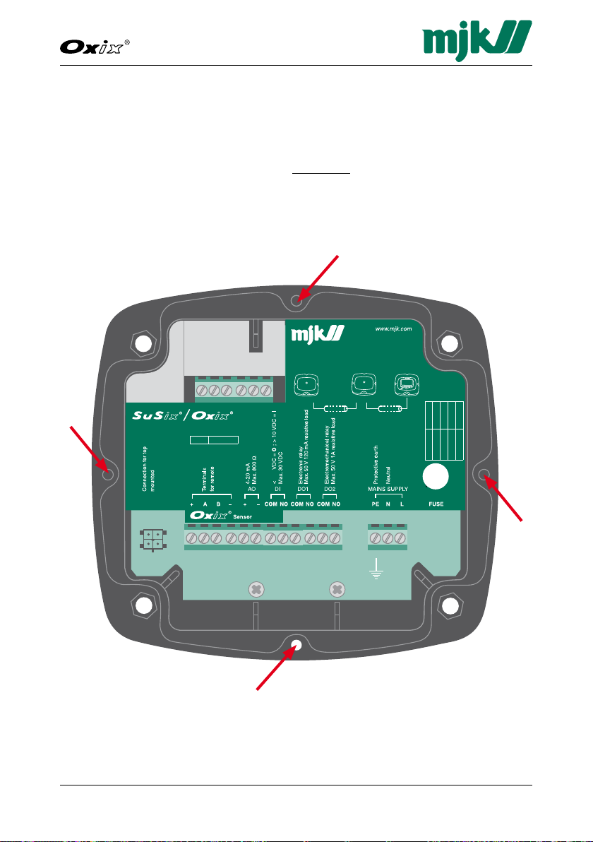
6. Converter
Electrical Mounting
Warning!
The Oxix® converter/display unit must not be mounted in
explosion hazardous areas!
Loosen the four screws (positions indicated by arrows) and remove the display unit to gain access to the terminals.
Page 24

24GB Oxix Manual 080915
FW: 841013-009, 846001-002, 841513-009
Dissolved Oxygen Transmitter
Power Supply
The flow converter must be supplied from a properly fused mains outlet, a 24
volt AC outlet, or a 10 - 30 V DC power supply/battery.
Power Supply 230 V AC, 115 V AC or 24 V AC
Terminal Designation
PE Protective ground
N 230 / 115 / 24 V AC neutral
L 230 / 115 / 24 V AC live
Power Supply 10 - 30 V DC
Terminal Designation
PE Protective ground
— DC neutral
+ DC live
The internal fuse ratings are:
Internal Fuse Ratings
Voltage Rating Order no. Dimension
230 V AC 0.063 mA T 550030 5 x 20 mm
115 V AC 0.125 mA T 550035 5 x 20 mm
24 V AC 0.5 mAT 550049 5 x 20 mm
10 - 30 V DC 1.0 AT 550051 5 x 20 mm
The technical specifications for a 10 - 30 V DC power supply/battery are:
Technical Specifications for 10 - 30 V DC Power Supply
Power consumption without display < 5 W
Power consumption with display < 8 W
Peak start current @12 V DC,1 second Approx. 1,5 A
Peak start current @24 V DC,1 second Approx. 1 A
Display Connector
The display wires (and the remote display extension cable) are colour coded
as follows:
Display Connector
Wire colour Designation
Red + supply
White RS-485 A
Grey RS-485 B
Black - supply
Page 25
25
Dissolved Oxygen Transmitter
GB Oxix Manual 080915
FW: 841013-009, 846001-002, 841513-009
Changing the Power Supply Voltage 230/115 V AC
To change the input mains voltage from 230 V AC to 115 V AC (or vice versa)
proceed as follows:
1. Loosen the four screws on the front and lift out the display (see also page
23).
2. Note down the color and position of the wires in the terminal blocks, and
then loosen the terminal screws.
3. Unscrew the two screws that hold the metal cover and then remove it.
4. Unscrew the four screws that hold the mother PCB (the printed circuit
board with all the electrical components).
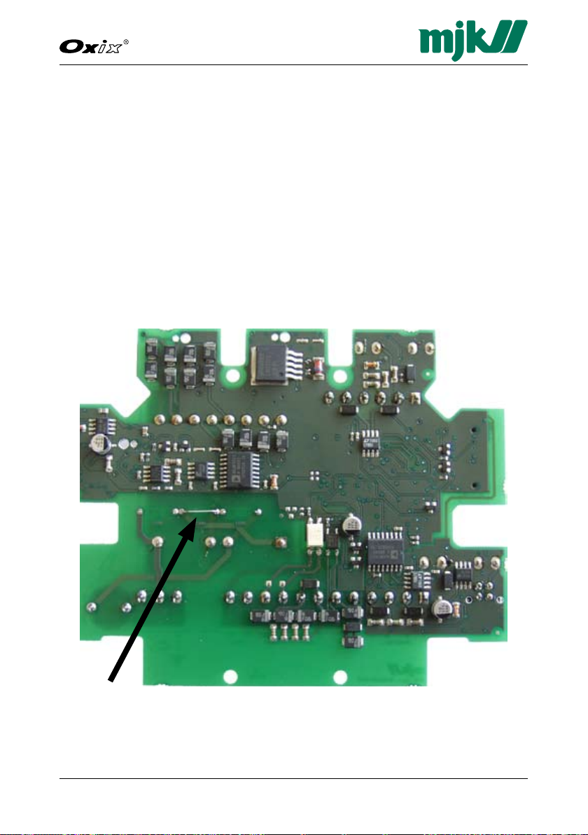
5. Remove the mother PCB and look at the back side.
This is what you should expect to see for a 230 V AC configuration:
230 V AC single jumper position
6. Unsolder and remove the jumper indicated by the arrow.
Page 26
26GB Oxix Manual 080915
FW: 841013-009, 846001-002, 841513-009
Dissolved Oxygen Transmitter
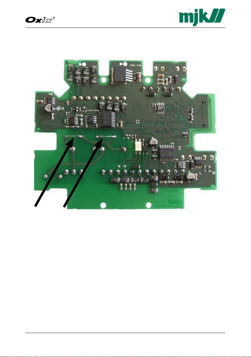
7. See on the following picture where two jumpers must be inserted for a 115
V AC configuration:
115 V AC dual jumper positions
8. Insert and solder 2 jumpers (wires) in the positions indicated by the black
arrows.
9. Turn around the PCB and replace the 63 mAT fuse on the right side with a
125 mAT fuse ( or vice versa going from 115 VAC to 230 VAC).
10. Re-insert the PCB and re-assemble the converter (see also steps 4, 3, 2
and 1).
Page 27

27
Dissolved Oxygen Transmitter
GB Oxix Manual 080915
FW: 841013-009, 846001-002, 841513-009
Analogue Output
The analogue output is an active output with a maximum load of 800Ω.
Analogue Output
Terminal Designation
AO + 4-20 mA
AO
-
4-20 mA
The analogue output can be programmed for indication of primary units.
See details on page 53.
Digital Output
Oxix® has two digital outputs - DO1 with an opto (light triggered) relay and
DO2 with an electro-mechanical relay.
They can both be programmed for the following functions:
- Sensor error
- High and low alarms
Opto Relay
Terminal Designation
DO1 Com Max. 50 V DC /120 mA
DO1 NO
Electro-mechanical relay
Terminal Designation
DO2 Com Max. 50 V DC /1 A
DO2 NO
DO1 shares the common terminal (Com) with DI.
See also application examples in Appendix E. Digital Input/Output Connections on page 101.
Page 28

28GB Oxix Manual 080915
FW: 841013-009, 846001-002, 841513-009
Dissolved Oxygen Transmitter
Digital Input
Oxix® has one digital input which can be activated with a voltage higher than
10 V DC and de-activated with a voltage lower than 5 V DC.
Digital Input
Terminal Designation
DI Com
DI Max. 30 V DC
The digital input (DI) can be programmed for the following functions:
- start and pause cleaning function
- Solid curve
See also application examples in Appendix E. Digital Input/Output Connections on page 101.
Page 29
29
Dissolved Oxygen Transmitter
GB Oxix Manual 080915
FW: 841013-009, 846001-002, 841513-009
Mains
supply
-mA- -D02--D01--DI--Display-
+ +A B C2 N02C NO N01 PE N L
- -
C1
+DCGND A B
Red
Black
White
Green
Shield
521275
Line
2 wire
shielded cable.
4 wire
shielded cable.
display unit
display unit
Display unitConverter #4Converter #1
Max. four MJK converters with Modbus
can be connected to one display unit:
521274
2,5
Main supply
Supply Fuse
10-30 V DC 1 A T
24 V AC 500 mA T
115 V AC 125 mA T
230 V AC 63 mA T
Sensor supply
Fuse 200 mA T
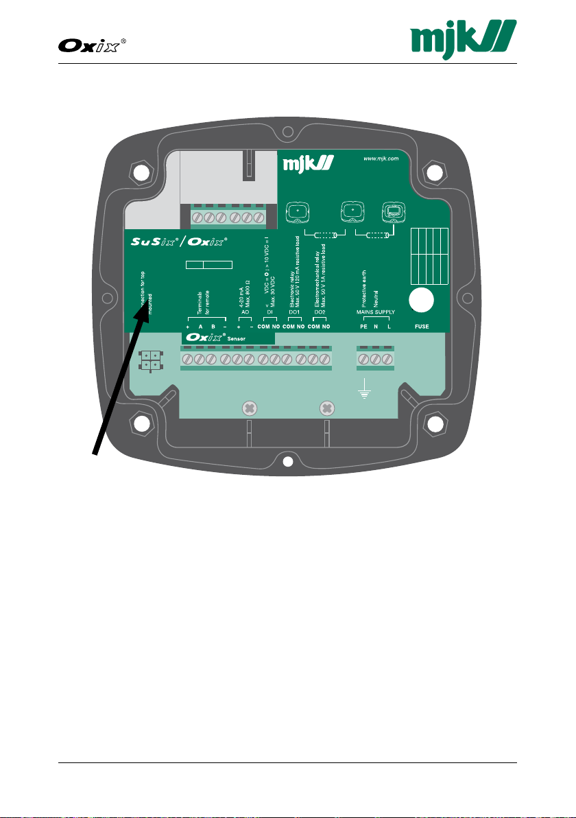
Converter Terminals
Oxix® converter terminals
Flip the green label with "SuSix® / Oxix®" printed on it (see arrow) to the right
to gain access to the sensor connection terminals (see next page).
Page 30
30GB Oxix Manual 080915
FW: 841013-009, 846001-002, 841513-009
Dissolved Oxygen Transmitter
Mains
supply
-mA- -D02--D01--DI--Display-
+ +A B C2 N02C NO N01 PE N L
- -
C1
Line
2 wire
shielded cable.
4 wire
shielded cable.
display unit
display unit
Display unitConverter #4Converter #1
Max. four MJK converters with Modbus
can be connected to one display unit:
521274
2,5
Main supply
Supply Fuse
10-30 V DC 1 A T
24 V AC 500 mA T
115 V AC 125 mA T
230 V AC 63 mA T
Sensor supply
Fuse 200 mA T
+DCGND A B
Red
Black
White
Green
Shield
521275
www.mjk.com
DK: +45 45 56 06 56
NO: +47 69 20 60 70
SE: +46 53 31 7 7 50
NL: +31 251 672171
USA: +1 847 482 8655
AUS: +61 3 9758 8533
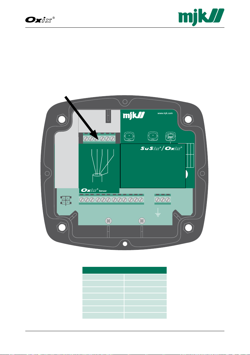
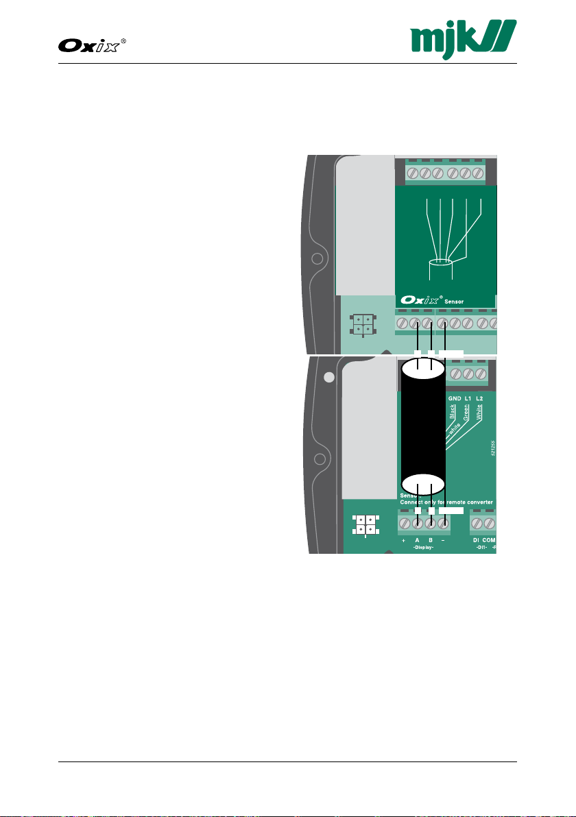
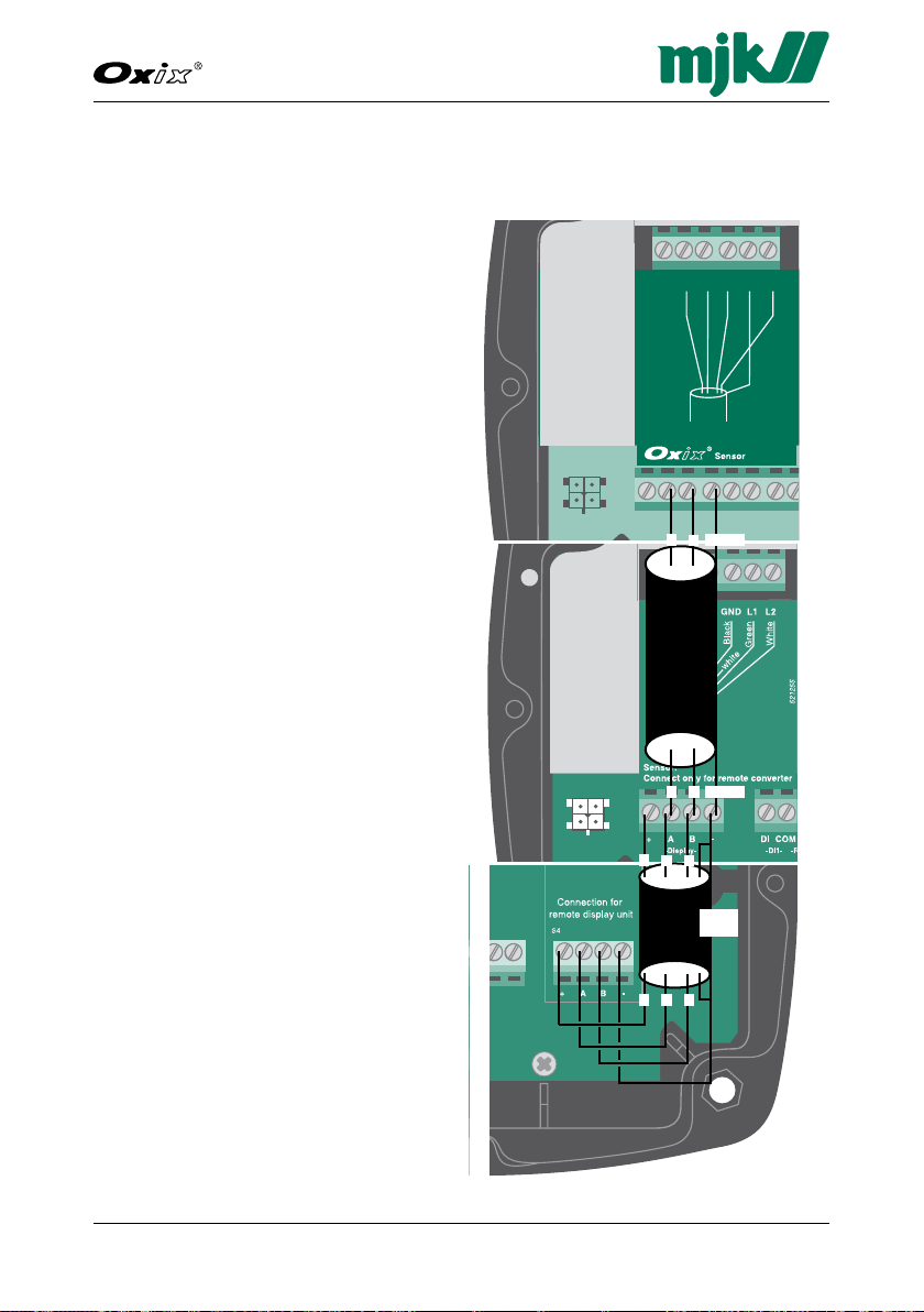
Sensor and Mounting Kit / Connection Board Terminals
Important!: Make sure the right wiring indication label is fitted below
the terminal block (label indicated by arrow). The label
must clearly be marked Oxix®.
Wrong wiring may cause sensor destruction !
Connect the sensor wires to the Oxix® converter with the wires coming from
the sensor as shown below (see arrow).
Terminals
Wires from sensor Converter terminals
Oxix® converter terminals
- not used
Black GND
White A
Green B
Shield - (shield GND)
Red +DC
Page 31

31
Dissolved Oxygen Transmitter
GB Oxix Manual 080915
FW: 841013-009, 846001-002, 841513-009
7. System Configuration Examples
MJK Oxix® transmitters share communication protocols with other MJK products like the MJK Magflux® flow meter and the MJK Connect data transmitter,
and can also share display units. This section illustrates two configuration
examples and includes cable connections and part numbers.
Magflux® with blind lid and Oxix® with display unit
Oxix® with blind lid, Magflux® with blind lid and a remote display unit
Page 32

32GB Oxix Manual 080915
FW: 841013-009, 846001-002, 841513-009
Dissolved Oxygen Transmitter
Magflux® with Blind Lid and Oxix® with Display Unit
Configuration: Magflux® flow sensor/converter with a blind lid connected
to a Oxix
Part numbers for this configuration:
2x7xxx MagFlux® Flow Sensor
2x7791x MagFlux® Connverter with blind lid
579035 MagFlux® Gel Potting Kit IP68
2-wire, shielded, twisted cable (Magflux® <--> Oxix®)
206510 Oxix® Sensor
206304-6 SuSix® /Oxix® Converter with Display Unit
®
transmitter with display unit
Page 33
33
Dissolved Oxygen Transmitter
GB Oxix Manual 080915
FW: 841013-009, 846001-002, 841513-009
Mains
supply
-mA- -D02--D01--DI--Display-
+ +A B C2 N02C NO N01 PE N L
- -
C1
Line
2 wire
shielded cable.
4 wire
shielded cable.
display unit
display unit
Display unitConverter #4Converter #1
Max. four MJK converters with Modbus
can be connected to one display unit:
521274
2,5
Main supply
Supply Fuse
10-30 V DC 1 A T
24 V AC 500 mA T
115 V AC 125 mA T
230 V AC 63 mA T
Sensor supply
Fuse 200 mA T
+DCGND A B
Red
Black
White
Green
Shield
521275
www.mjk.com
DK: +45 45 56 06 56
NO: + 47 69 20 60 70
SE: +46 53 31 77 50
NL: +31 25 1 672171
USA: +1 847 482 8655
AUS: +61 3 9758 8533
Wiring Schematic #1
for " Magflux® with Blind Lid and Oxix® with Display Unit" from the opposite
page (page 32).
Oxix® with Display Unit
2-wire, shielded twisted cable
1. Connect lead "1" to slot "Display A"
2. Connect lead "2" to slot "Display B"
3. Connect the twisted shield to slot
"Display -"
12Shield
Magflux® with Blind Lid
2-wire, shielded twisted cable
1. Connect lead "1" to slot "Display A"
2. Connect lead "2" to slot "Display B"
3. Connect the twisted shield to slot
"Display -"
12Shield
Page 34

34GB Oxix Manual 080915
FW: 841013-009, 846001-002, 841513-009
Dissolved Oxygen Transmitter
SuSix® with Blind Lid, Magflux® with Blind Lid and a Remote Display
Configuration: An Oxix® transmitter with a blind lid connected to a Magflux® flow sensor with a blind lid and common remote Display Unit.
Part numbers for this configuration:
206510 Oxix® Sensor
206304-6 SuSix® /Oxix® Converter
2x7xxx MagFlux® Flow Sensor
2x791x MagFlux® Converter with blind lid
579035 MagFlux® Gel Potting Kit IP68
207930 Wall Mounting Kit
2-wire, twisted shield cable (Oxix® <--> Magflux®)
4-wire, twisted shield cable (Magflux® <--> Display Unit)
Page 35
35
Dissolved Oxygen Transmitter
GB Oxix Manual 080915
FW: 841013-009, 846001-002, 841513-009
Mains
supply
-mA- -D02--D01--DI--Display-
+ +A B C2 N02C NO N01 PE N L
- -
C1
Line
2 wire
shielded cable.
4 wire
shielded cable.
display unit
display unit
Display unitConverter #4Converter #1
Max. four MJK converters with Modbus
can be connected to one display unit:
521274
2,5
Main supply
Supply Fuse
10-30 V DC 1 A T
24 V AC 500 mA T
115 V AC 125 mA T
230 V AC 63 mA T
Sensor supply
Fuse 200 mA T
+DCGND A B
Red
Black
White
Green
Shield
521275
www.mjk.com
DK: +45 45 56 06 56
NO: + 47 69 20 60 70
SE: +46 53 31 77 50
NL: +31 25 1 672171
USA: +1 847 482 8655
AUS: +61 3 9758 8533
Wiring Schematic #2
for "Oxix® with Blind Lid and a Magflux® with Blind Lid connected to a common wall mounted Display Unit" on the opposite page (page 34).
Oxix® with Blind Lid
2-wire, shielded twisted cable
1. Connect lead "1" to slot "Display A"
2. Connect lead "2" to slot "Display B"
3. Connect the twisted shield to slot
"Display -"
®
Magflux
2-wire, shielded twisted cable
1. Connect lead "1" to slot "Display A"
2. Connect lead "2" to slot "Display B"
3. Connect the twisted shield to slot
"Display -".
4-wire, shielded twisted cable
1. Connect lead "1" to slot "Display +"
2. Connect lead "2" to slot "Display A"
3. Connect lead "3" to slot "Display B"
4. Connect the twisted shield to slot
"Display -".
with Blind Lid
12Shield
12Shield
1
2
3
Wall Mounted Display Unit
4-wire, shielded twisted cable
1. Connect lead "1" to slot "Display +"
2. Connect lead "2" to slot "Display A"
3. Connect lead "3" to slot "Display B"
4. Connect the twisted shield to slot
"Display -".
4 and
shield
1
2
3
Page 36

36GB Oxix Manual 080915
FW: 841013-009, 846001-002, 841513-009
Dissolved Oxygen Transmitter
This page intentionally left blank.
Page 37

37
Dissolved Oxygen Transmitter
GB Oxix Manual 080915
FW: 841013-009, 846001-002, 841513-009
8. Startup
Initial Checks before Power-up
Before switching on power the following steps must be checked.
1. The local mains power supply voltage corresponds to the voltage printed
on the identification label of the transmitter.
2. All electrical connections are made in accordance with the electrical connection diagram shown with special emphasis on the sensor connection
described on page 30.
3. All terminal screws are tightened.
4. All cable glands are tightly secured.
5. All grounding connections are made in accordance with the instructions in
this manual (see page 21).
Initial Power-up
1. Turn on power.
2. Within 60 seconds the Oxix
sor detection program. During this process you might briefly see "SuSix1"
and/or "MagFlux1" on the display. This is normal and to be expected.
®
sensor will be found by the automatic sen-
Initial Measurement
1. Make sure that the sensor is completely covered by liquid.
2. Turn on power to the transmitter and wait 15 minutes before taking the
initial measurement.
Language Selection
1. The default display language is English. If another language is required,
proceed with step 2.
2. Select "Display Setup" from the Main Menu.
3. Select "Language" from the Display Setup menu and chose the required
language (see page 73).
Page 38
38GB Oxix Manual 080915
FW: 841013-009, 846001-002, 841513-009
Dissolved Oxygen Transmitter
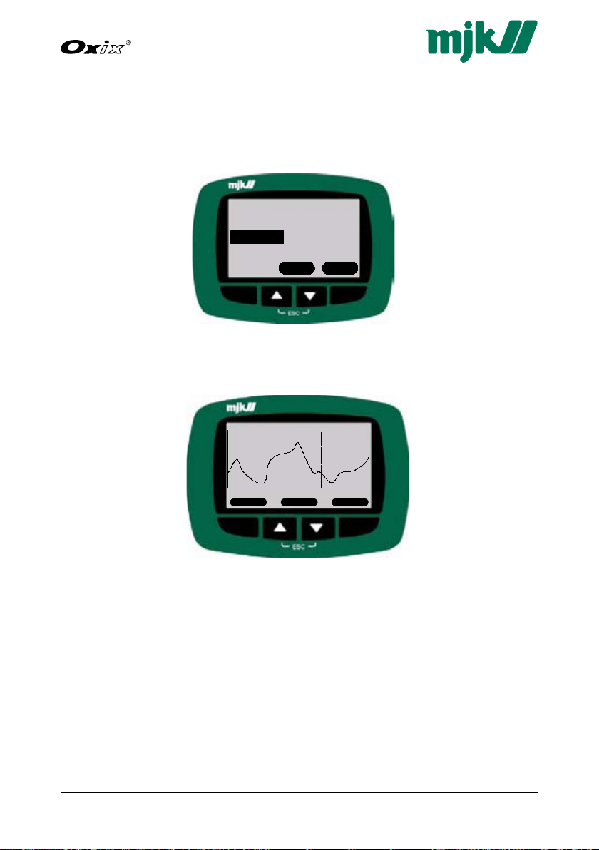
Oxix1
Oxygen sat.
%
Select Set up
Converter Overview Menu
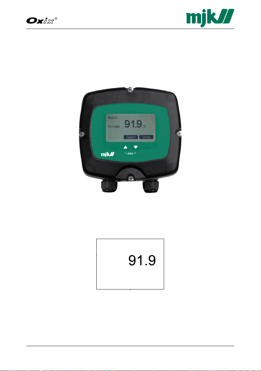
Display Read-out, one connected unit
All Oxix® display read-outs are illustrated and described in this manual.
Chapter 6. Oxix® Menus (on page 41) gives a detailed description of the 5-line
LCD screen displays shown during setup, configuration and normal operation.
Display and keyboard for reading and programming
The display shown above will in the remaining part of this manual be stylized to
appear like this:
Page 39

39
Dissolved Oxygen Transmitter
GB Oxix Manual 080915
FW: 841013-009, 846001-002, 841513-009
Oxix1
Oxygen sat.
%
Converter Overview Menu
Oxix1 91.9 %
Susix1 578 mg/L
Back Select Display
Oxix1
Oxygen sat.
%
Select Set up
Converter Overview Menu
Specify Main Screen
Data Logger
Password
Set Sensor Name
Converter Setup
Display Setup
Back Select OK
Select line
Linie 1 - Sensor name
Linie 2 - Meas.
Linie 3 -
Linie 4 -
Linie 5
Back Select OK
Specify Main Screen
Select line content
SuSix1 [X]
Meas.
FTU
Select Setup
Main Menu
Converter Top Display
SuSix1 [X]
Meas.
FTU
Select Setup
Converter Top Display
Specify Main Screen
Data Logger
Password
Set Sensor Name
Converter Setup
Display Setup
Back Select OK
Main Menu
SuSix1 [X]
Prim.
mg/l
Second 0.1%
Select Setup
Display Read-out, several connected units
When several MJK units are interconnected, for example an Oxix® dissolved
oxygen transmitter and a SuSix® turbidity and suspended solids transmitter
with different names and Modbus ID numbers, a "Display Overview Menu" is
available at top level (press "Back" repeatedly):
All connected units are displayed and sorted by their ID numbers, and consequently each unit can be selected and set up as required:
Important:
More connected units can only by managed as described above, if each
unit have been assigned a unique name and Modbus ID number. See
page 75 for details.
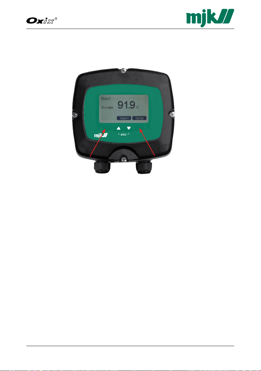
Display Keys
The keys and the soft keys (variable key functions determined by the display
firmware) are used for initial programming and normal operation of the flow
meter.
The function(s) of the four available keys is displayed at the bottom of the display. The symbols and actual functions are described in detail in the sections
that describe the individual menus.
or
Page 40
40GB Oxix Manual 080915
FW: 841013-009, 846001-002, 841513-009
Dissolved Oxygen Transmitter
Contrast Adjustment
Adjust the display contrast by pressing the two outmost keys simultaneously
(indicated by the keys) and press the up/down keys as required.
Save the new setting by pressing the two outmost keys simultaneously.
System Reset
You can reset and refresh all system displays and key combinations by pressing all four keys simultaneously. It is a so-called coldboot, where all displays
are refreshed and all settings/configurations are kept with only one exception:
the language setting.
This feature is especially useful during for example a service call, where the
display language (Dutch, Danish, Swedish etc.) cannot be understood by the
local serviceperson. A system reset immediately sets the display language to
(GB) English.
The system reset must not be confused with the ultimate "Recover factory
settings" (see page 60) which deletes all local configurations/settings and
replaces them with default factory settings.
Page 41

41
Dissolved Oxygen Transmitter
GB Oxix Manual 080915
FW: 841013-009, 846001-002, 841513-009
Oxix1
Oxygen sat.
%
Select Set up
Converter Overview Menu
Specify main Screen
Datalogger
Password
Sensor name
Converter setup
Display setup
Back Select OK
Login
Set log interval
Datalogger
Select line
Specify main Screen Converter setup
Password
Oxix1
Oxygen sat.
%
Select Set up
Main Menu
Converter Overview Menu
9. Oxix® Menus
All the Oxix® menus and sub menus are shown and described in the following
sections.
Continous overviews of the menu and sub-menu structures are presented at
the end of this manual:
Converter Overview Menu• (page 102)
Main Menu Overview• (page 102)
Converter Setup Overview• (page 106)
Service Menu Overview• (page 114)
Display Setup Menu Overview• (page 120)
Converter Overview Menu
1. Press the "Setup" key on the Oxix® display (see below) to enter the Oxix®
Converter Overview Menu.
2. Press the up/down keys to highlight the required menu line in the Main
Menu (here: Specify main screen) and then press OK to select it.
Main Menu
Page 42

42GB Oxix Manual 080915
FW: 841013-009, 846001-002, 841513-009
Dissolved Oxygen Transmitter
Login
Activate/deactivate
Set new password
Back Select OK
Set log interval
0020 sec
Back Select >
Datalogger
Sensor name
Oxix 1
Back Select >
Sensor name
Select line
Linie 1 - Sensor name
Linie 2 - Oxygen sat.
Linie 3 Linie 4 Linie 5
Back Select OK
Specify main Screen Converter setup
Select line content
Not in use
Sensor name
Measurement
Temperature
Clock
Back Select OK
Password
Type password
0000
Back Select >
Set new password
Back Select >
Activate
Deactivate
Back Select OK
Login
Activate/
Deactivate
Set new password
Specify Main Screen
The "Specify Main Screen" menu allows you to customize the Oxix® display
to suit your requirements. You can add and remove five available display lines
and name/configure them individually.
1. Press the up/down keys to highlight the required menu line and then press
OK to select it.
2. Press the up/down keys to highlight the required option and press OK.
The available options are:
Not in use
The line not used. The freed space will be used by the other lines.
Sensor name
TBD
Measurement
Measurement displays the measured values in time in the predefined unit:
%, mg/l or ppm.
Note: The units are defined later on in the "Converter setup/Units" menu on
page 52.
Page 43

43
Dissolved Oxygen Transmitter
GB Oxix Manual 080915
FW: 841013-009, 846001-002, 841513-009
Temperature
The temperature may be displayed in degrees Celcius (ºC) or in degrees
Fahrenheit (ºF). See also page 52.
Clock
Time and date
The size of the display lines will automatically increase or decrease as the
number of display lines is removed or added to maximize the field of view
for the measured values
Page 44

44GB Oxix Manual 080915
FW: 841013-009, 846001-002, 841513-009
Dissolved Oxygen Transmitter
Specify main Screen
Datalogger
Password
Sensor name
Converter setup
Display setup
Back Select OK
Login
Activate/deactivate
Set log interval
0020 sec
Datalogger
Select line
Linie 1 - Sensor name
Specify main Screen Converter setup
Password
Oxix1
Oxygen sat.
%
Select Set up
Main Menu
Converter Overview Menu
Login
Activate/deactivate
Set new password
Back Select OK
Set log interval
0020 sec
Back Select >
Datalogger
Sensor name
Oxix 1
Back Select >
Sensor name
Averaging
Units
mA output
Cleaning
High Alarm
Password
Datalogger
Oxix® provides a data logger with a capacity of approx. 20,000 entry
points. See Appendix D on page 97 for examples and descriptions of log
files.
The data logger operates after the FIFO principle (First In, First Out). If the
data logger is full and new data are coming in, the oldest data are discarded.
1. Press the up/down keys to highlight the required menu line
(here: Datalogger) and then press OK to select it.
2. Press the up/down keys to change the highlighted digit, and then press
the right-key (>) to proceed to the next digit.
3. Continue until all digits have been set and press OK.
The log interval can be set in intervals from 10 seconds up to 9999
seconds.
Page 45

45
Dissolved Oxygen Transmitter
GB Oxix Manual 080915
FW: 841013-009, 846001-002, 841513-009
The data log contains:
Date•
Time•
Dissolved oxygen values •
In case of a power failure, the data logger continues when power returns.
If more converters are connected to one Display Unit, each converter has its
own individual log interval and can be sorted.
All converters share the same memory of 20.000 entry points.
The log data can be shown on the Display Unit or be stored in an external
CSV file. MJK-Field Link software is needed for transfer of data into CSV file
format via the USB port in the display unit. The format can be read in for example Microsoft
®
Excel® (see Appendix D on page 97 for details).
An example of the log capacity of one sensor versus the time interval is
shown in the following table.
Log interval Log capacity
Seconds Minutes Hours Days
10 - 55,56 2,31
30 - 166,67 6,94
- 1 333 14
- 5 1667 69
- 10 3333 139
- 30 10000 417
- 60 20000 833
Page 46
46GB Oxix Manual 080915
FW: 841013-009, 846001-002, 841513-009
Dissolved Oxygen Transmitter
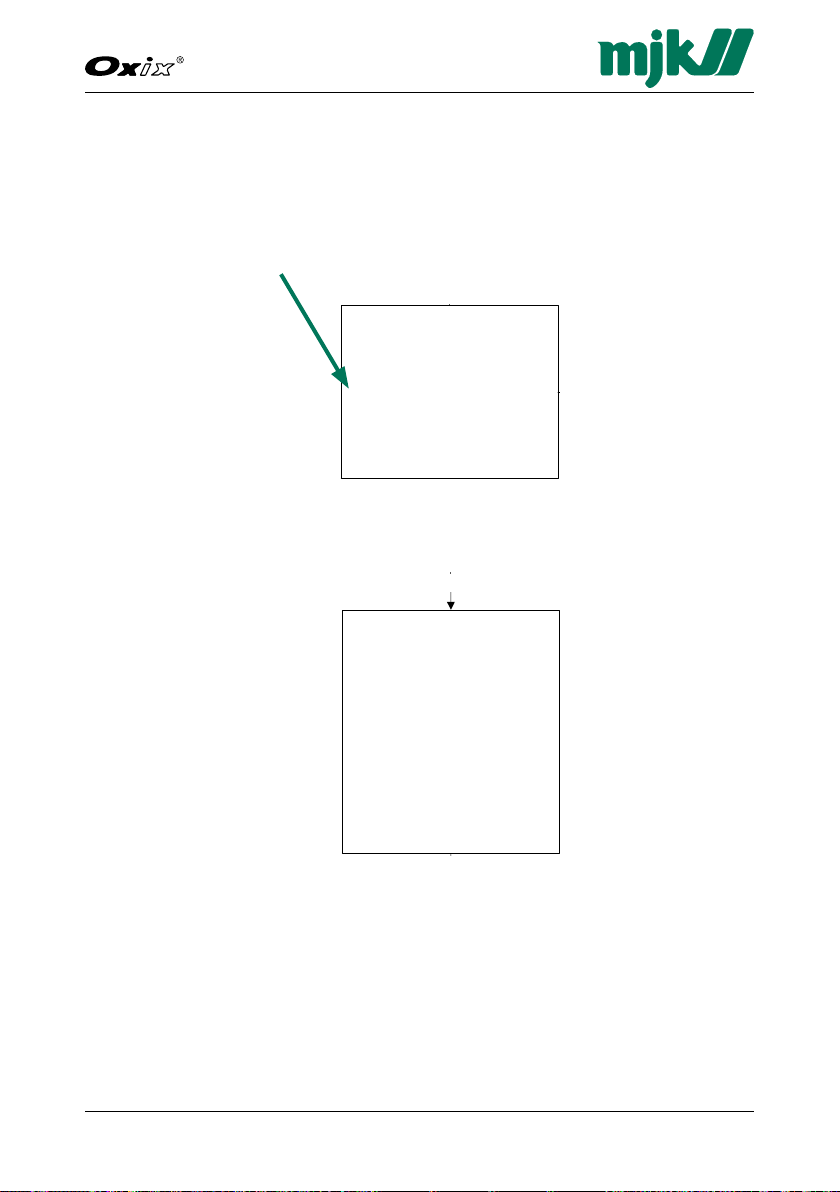
Oxix1
Oxygen
98 %
Select Graph
100 %
2008-09-21
11:25:43 84 %
<< >>< >
Oxix1
Oxygen
98 %
Select Graph
Graph Display
The content of the Data Logger can displayed on the Display Unit by pressing
the up/down keys, highlighting "Oxygen sat." and selecting "Graph"
The Display Unit then shows the Graph screen. To return to the Main Menu
display screen, select "esc" by pressing the up/down keys simultaneously.
The Y axis is automatically scaled according to the maximum value of the mA
output.
Double-arrow keys jump forward and backward one screen frame at a time.
Single-arrow keys move the cursor forward and backward on the screen.
The actual values at the cursor position is shown at the bottom of the screen.
Page 47

47
Dissolved Oxygen Transmitter
GB Oxix Manual 080915
FW: 841013-009, 846001-002, 841513-009
Specify main Screen
Datalogger
Password
Sensor name
Converter setup
Display setup
Back Select OK
Login
Set log interval
Datalogger
Select line
Specify main Screen Converter setup
Password
Oxix1
Oxygen sat.
%
Select Set up
Main Menu
Converter Overview Menu
Login
Activate/deactivate
Set new password
Back Select OK
Set log interval
0020 sec
Back Select >
Datalogger
Sensor name
Oxix 1
Back Select >
Sensor name
Averaging
Units
mA output
Cleaning
High Alarm
Low Alarm
Sensor Error
Status
Factory settings
Service menu
Back Select OK
Password
Type password
0000
Back Select >
Set new password
0000
Back Select >
Activate
Deactivate
Back Select OK
Login
Activate/
Deactivate
Set new password
Password
A password provides (and prevents) access to all the settings in the Display
and Converter unit. The code consists of a numeric 5-digit code between
0 and 65535. If your current password is lost or forgotten, contact MJK for
instructions.
1. Press the up/down keys to highlight the required menu line
(here: Password) and then press OK to select it.
2. Press the up/down keys to highlight the required option and then press
OK to select it.
The available options are:
Login
Use the up/down keys to set the digits one by one. Continue with > until
all digits have been set and then press OK.
Page 48

48GB Oxix Manual 080915
FW: 841013-009, 846001-002, 841513-009
Dissolved Oxygen Transmitter
Activate/deactivate
Write protection. Selecting "Activate" means that a password must be en-
tered to change vital settings. "Deactivate" disables password protection.
If your current password is lost or forgotten, the password protection can
be overruled with the code "01750".
Change password
The present 5-digit password can be changed as required.
Page 49

49
Dissolved Oxygen Transmitter
GB Oxix Manual 080915
FW: 841013-009, 846001-002, 841513-009
Specify main Screen
Datalogger
Password
Sensor name
Converter setup
Display setup
Back Select OK
Login
Set log interval
Datalogger
Select line
Specify main Screen Converter setup
Password
Oxix1
Oxygen sat.
%
Select Set up
Main Menu
Converter Overview Menu
Sensor Name
A unique name and/or number, a function or a location can be assigned for a
sensor (here: "Oxix1"). It is consequently shown on the main display with up
to 4 display lines.
1. Press the up/down keys to highlight the required menu line
(here: Sensor Name) and then press OK to select it.
2. To change the default sensor name "Oxix1" to for example "Aeration Tank
Inlet", press the left/right keys to highlight the wanted character.
Page 50

50GB Oxix Manual 080915
FW: 841013-009, 846001-002, 841513-009
Dissolved Oxygen Transmitter
Specify main Screen
Datalogger
Password
Sensor name
Converter setup
Display setup
Back Select OK
Set log interval
0020 sec
Back Select >
Datalogger
Select line
Linie 1 - Sensor name
Linie 2 - Oxygen sat.
Linie 3 -
Linie 4 -
Linie 5
Back Select OK
Specify main Screen Converter setup
Select line content
Not in use
Sensor name
Login
Oxix1
Oxygen sat.
%
Select Set up
Main Menu
Converter Overview Menu
Oxix1 91.9 %
Susix1 578 mg/L
Back Select Display
Display setup
Sensor name
Aeration Tank Inlet
Back Select >
Sensor name
3. Press the up/down keys to change the highlighted character and then
press > to proceed to the next character.
4. Continue with > until all numeric and alphabetical characters have been
set.
5. Press OK.
The available characters depend on the chosen language. English, for example, provides the following character set:
a b c d e f g h i j k l m n o p q r s t u v w x y z A B C D E F G H I J K L M N O
P Q R S T U V W X Y Z <space> 1 2 3 4 5 6 7 8 9 and 0.
Page 51
51
Dissolved Oxygen Transmitter
GB Oxix Manual 080915
FW: 841013-009, 846001-002, 841513-009
Specify main Screen
Datalogger
Password
Sensor name
Converter setup
Display setup
Back Select OK
Login
Set log interval
Datalogger
Select line
Specify main Screen Converter setup
Password
Oxix1
Oxygen sat.
%
Select Set up
Main Menu
Converter Overview Menu
Converter setup
Language
Set Clock
Modbus
Factory settings
Display SW version
Back Select OK
Display setup
Averaging
Units
mA output
Cleaning
High Alarm
Low Alarm
Sensor Error
Status
Factory settings
Service menu
Back Select OK
Converter Setup
"Converter setup" provides configuration options for calibration, alarms, units,
etc. See detailed descriptions in the following sections, and a continuous
overview on page 106 at the end of this manual.
1. Press the up/down keys to highlight the required menu line (here:
Converter setup) and then press OK to select it.
2. A number of options appears beginning with "Averaging":
Page 52

52GB Oxix Manual 080915
FW: 841013-009, 846001-002, 841513-009
Dissolved Oxygen Transmitter
Averaging
Units
mA output
D.O. Units
%
mg/l
ppm
Enable mA output?
Yes
No
Back Select OK
Averaging
0001 sec
(from 1 sec to 120 min)
Back Select >
This menu is for display only.
Cleaning
Electro-mechanical relay
Opto relay
Not in use
Back Select OK
Units
mA output
D.O. Units
%
mg/l
ppm
Back Select OK
4mA output
4 mA = 00.00 mg/l
Back Select OK
Yes
Enable mA output?
Yes
No
Back Select OK
Temperature unit
°C
°F
Back Select OK
Temperature
This menu is for display only.
Cleaning
Interval
Use DI to clean
Clean now
Maintenance
Back Select OK
Electro-mechanical relay
Opto relay
Not in use
Back Select OK
Averaging
To avoid unwanted fluctuations in the measurement reading, the "Averaging"
options smoothes the measurements over a predefined period of time.
Units
The measuring and temperature units can be set from this menu.
Page 53

53
Dissolved Oxygen Transmitter
GB Oxix Manual 080915
FW: 841013-009, 846001-002, 841513-009
mA output
20 mA output
20 mA = 25.00 mg/l
Back Select OK
4mA output
4 mA = 00.00 mg/l
Back Select OK
Yes
Enable mA output?
Yes
No
Back Select OK
Clean now
Yes
No
Clean now
Cleaning
Interval
Use DI to clean
Clean now
Maintenance
Back Select OK
Interval
Off
On
Use DI to cleanInterval Maintenance
Use DI to clean
No
Yes
Electro-mechanical relay
Opto relay
Not in use
Back Select OK
mA Output
When a Oxix® is connected to a power supply for the first time, the mA output is automatically set to provide 4 mA at zero and 20 mA at the theoretical
maximum value.
Changes in the mA setting will not affect the relay output settings.
Note: Both values can be set in the range 10 % to 120 %, making it
possible to increase or decrease the mA signal.
The mA output is an active output, and the maximum load is 800 Ohm.
The upper limit for the mA output is 20,5 mA
3,75 mA indicates the mA output is not in use
3,5 mA indicates values under 4 mA level
20,5 mA indicates value higher than 20 mA level.
Page 54

54GB Oxix Manual 080915
FW: 841013-009, 846001-002, 841513-009
Dissolved Oxygen Transmitter
Clean now
Yes
No
Back Select OK
Reset Maintenance
Yes
No
Back Select OK
Maintenance
Runtime 1000 hour
Count 500
Back Select OK
Clean now
Select cleaning interval
060 Min
(20 - 255 Min)
Back Select >
Cleaning
Interval
Use DI to clean
Clean now
Maintenance
Back Select OK
Interval
Off
On
Back Select OK
Use DI to clean
Interval Maintenance
DI function
NO
NC
Back Select OK
Use DI to clean
No
Yes
Back Select OK
Delay
00100 ms
Back Select >
Electro-mechanical relay
Opto relay
Not in use
Back Select OK
Cleaning time
005 sec
Back Select OK
Cleaning time
005 sec
Back Select OK
Measurement delay
10 sec
Back Select OK
Cleaning
Air or water jet cleaning can be defined based on local conditions.
Page 55

55
Dissolved Oxygen Transmitter
GB Oxix Manual 080915
FW: 841013-009, 846001-002, 841513-009
Clean now
Yes
No
Back Select OK
Reset Maintenance
Yes
No
Back Select OK
Maintenance
Runtime 1000 hour
Count 500
Back Select OK
Clean now
Use DI to cleanInterval Maintenance
DI function
NO
NC
Back Select OK
Use DI to clean
No
Yes
Back Select OK
Delay
00100 ms
Back Select >
Cleaning time
005 sec
Back Select OK
A typical cleaning interval for aeration basins would be 2 hours (120 minutes).
In colder climates, condensation may form and then freeze in the tubing. This
can be prevented by setting the interval to 5 - 20 minutes.
The cleaning time would typically be 30 seconds.
The measurement delay (recovery time) may also be used to coordinate with
other processes. The delay merely freezes the last reading before cleaning
begins. A typical value would be 60 seconds.
Page 56

56GB Oxix Manual 080915
FW: 841013-009, 846001-002, 841513-009
Dissolved Oxygen Transmitter
On Setpoint
5,50 %
Back Select >
Relay function
NO
NC
Back Select >
Off Setpoint
5,75 %
Back Select >
Delay
00100 ms
Back Select >
Electro-mechanical relay
On Setpoint
7,00 %
Back Select >
High Alarm
Relay function
NO
NC
Back Select >
Off Setpoint
6,75 %
Back Select >
Electro-mechanical relay
Opto relay
Display only
Not in use
Back Select OK
Delay
00100 ms
Back Select >
Electro-mechanical relay
Opto relay Display only
On Setpoint
7,00 %
Back Select >
Relay function
NO
NC
Back Select >
Off Setpoint
6,75 %
Back Select >
Delay
00100 ms
Back Select >
On Setpoint
7,00 %
Back Select >
Off at flow
6,75 %
Back Select >
Delay
00100 ms
Back Select >
High alarm
A set point can be set to trigger an alarm (here: a high alarm) and to activate
one of two relays or simply to display the alarm on the display.
Page 57

57
Dissolved Oxygen Transmitter
GB Oxix Manual 080915
FW: 841013-009, 846001-002, 841513-009
Electro-mechanical relay
Delay
00100 ms
Back Select >
mA indication
High
Low
Off
Back Select OK
Relay function
NO
NC
Back Select OK
Low Alarm
Electro-mechanical relay
Opto relay
Display only
Not in use
Back Select OK
On Setpoint
5,50 %
Back Select >
Relay function
NO
NC
Back Select >
Off Setpoint
5,75 %
Back Select >
Delay
00100 ms
Back Select >
Opto relay
Display only
On Setpoint
5,50 %
Back Select >
Relay function
NO
NC
Back Select >
Off Setpoint
5,75 %
Back Select >
Delay
00100 ms
Back Select >
On Setpoint
5,50 %
Back Select >
Off Setpoint
5,75 %
Back Select >
Delay
00100 ms
Back Select >
Electro-mechanical relay
Low alarm
A set point can be set to trigger an alarm (here: a low alarm) and to activate
one of two relays or simply to display the alarm on the display.
Page 58

58GB Oxix Manual 080915
FW: 841013-009, 846001-002, 841513-009
Dissolved Oxygen Transmitter
Sensor error
Electro-mechanical relay
Opto relay
Display only
Not in use
Back Select OK
Electro-mechanical relay
Opto relay
Display only
Delay
00100 ms
Back Select >
Delay
00100 ms
Back Select >
Delay
00100 ms
Back Select >
Relay function
NO
NC
Back Select OK
mA indication
High
Low
Off
Back Select OK
mA indication
High
Low
Off
Back Select OK
mA indication
High
Low
Off
Back Select OK
Relay function
NO
NC
Back Select OK
Sensor error
Oxix® has two digital outputs - DO1 with an opto (light triggered) relay and
DO2 with an electro-mechanical relay. They can both be programmed for a
sensor error, whenever the 4 - 20 mA range has been exceeded.
Page 59

59
Dissolved Oxygen Transmitter
GB Oxix Manual 080915
FW: 841013-009, 846001-002, 841513-009
Type password
00000
Back Select >
Service menu
Pending errors
xxx
xxx
Back Select OK
Factory setting
Recover factory settings
Cancel
Default
Force to SuSix
Force to Oxix
Back Select OK
Status
DO 1 [ x ] Selected function
DO 1 [ \ ] Selected function
DI [ ] Selected function
mA output 10,234 mA
Back Select OK
Pending warnings
xxx
xxx
Back Select OK
Pending information
xxx
xxx
Back Select OK
Pending alarms
xxx
xxx
Back Select OK
Status
The "Status" option provides an overview of the in- and output status.
The check boxes can contain four different characters:
X A cross (X) in a check box indicates an active state
/ A blinking forward slant (/) in a check box indicates that the input/
output is in the process of being activated. Eventually it turns into a
steady X.
Page 60

60GB Oxix Manual 080915
FW: 841013-009, 846001-002, 841513-009
Dissolved Oxygen Transmitter
Type password
00000
Back Select >
Service menu
Factory setting
Recover factory settings
Cancel
Default
Force to SuSix
Force to Oxix
Back Select OK
\ A blinking backward slant (\) in a check box indicates that the
input/output is in the process of being de-activated. Eventually the
check box is cleared.
An empty check box indicates a de-activated state.
DO 1 [ X ] Selected function
The selected function linked to digital output D01 is active (an "X" in the
check box).
DO 2 [ X ] Selected function
The selected function linked to digital output D02 is in the process of be-
ing de-activated (an "X" in the check box).Digital output D02 for Totalizer
Forward is activated (a ticked check box).
DI [ ] Selected function
The selected function linked to digital input DI de-activated (an empty
check box). A "selected function" could for example be "Cleaning".
mA output 10.234 mA
The present analog output current is 10.234 mA. Pending errors, alarms,
warnings and infos are displayed for the selected in- or output.
Factory settings
The "Factory settings" menu provides resetting to the original factory settings
(except for the language setting).
Page 61

61
Dissolved Oxygen Transmitter
GB Oxix Manual 080915
FW: 841013-009, 846001-002, 841513-009
Sensor Data
Sensor Calibration
Converter SW. Version.
Product data
Reset Counter Time
Internal meas. & cal.
Calibrate mA
Test Primary value
Read eventlog
Comunication log
Back On Stock
Autodetect sensor type
Main supply frequency
Back Select OK
Sensor data
Sensor serial number
30487
Sensor software version
2
Back OK
Converter 846001-002
Bootload 840020-002
Back
Set actual measurement
10,20 mg/l
Back Select OK
Sensor calibration
Sensor calibration
1 point calibration
2 point calibration
Cancel
Back Select OK
OK
Clear calibration
No
Yes
Back Select OK
Confirm zero oxygen
No
Yes
Back Select OK
1 point
2 point
Type password
00000
Back Select >
Service menu
Sensor Data
Sensor Calibration
Converter SW. Version.
Product data
Reset Counter Time
Internal meas. & cal.
Calibrate mA
Test Primary value
Read eventlog
Comunication log
Back On Stock
Autodetect sensor type
Main supply frequency
Back Select OK
Sensor data
Sensor serial number
30487
Sensor software version
2
Back OK
Converter 846001-002
Bootload 840020-002
Back
Sensor calibration
Sensor calibration
1 point calibration
2 point calibration
Cancel
Back Select OK
OK
Service Menu - Digest
The "Service Menu" provides options intended for service personnel during
installation, calibration, operation, monitoring and maintenance.
All parameters can be read without any restrictions, but certain parameters
can only by changed after a password has been typed.
Page 62
62GB Oxix Manual 080915
FW: 841013-009, 846001-002, 841513-009
Dissolved Oxygen Transmitter
Averaging
Units
mA output
Converter setup
D.O. Units
%
mg/l
ppm
Back Select OK
Averaging
Units
mA output
Cleaning
High alarm
Low alarm
Sensor error
Status
Factory settings
Service menu
Back Select OK
Yes
Enable mA output?
Yes
No
Back Select OK
Averaging
0001 sec
(from 1 sec to 120 min)
Back Select >
This menu is for display only.
Sensor Data
Sensor Calibration
Converter SW. Version.
Product data
Reset Counter Time
Internal meas. & cal.
Calibrate mA
Test Primary value
Read eventlog
Comunication log
Back On Stock
Autodetect sensor type
Main supply frequency
Back Select OK
Sensor data
Sensor serial number
30487
Sensor software version
2
Back OK
Converter 846001-002
Bootload 840020-002
Back
Set actual measurement
10,20 mg/l
Back Select OK
Sensor calibration
Sensor calibration
1 point calibration
2 point calibration
Cancel
Back Select OK
OK
Clear calibration
No
Yes
Back Select OK
Confirm zero oxygen
No
Yes
Back Select OK
1 point
2 point
Type password
00000
Back Select >
Service menu
Sensor Data
Sensor Calibration
Converter SW. Version.
Product data
Reset Counter Time
Internal meas. & cal.
Calibrate mA
Test Primary value
Read eventlog
Comunication log
Back On Stock
Autodetect sensor type
Main supply frequency
Back Select OK
Sensor data
Sensor serial number
30487
Sensor software version
2
Back OK
Converter 846001-002
Bootload 840020-002
Back
Sensor calibration
Sensor calibration
1 point calibration
2 point calibration
Cancel
Back Select OK
OK
Service Menu - Detailed
The "Service Menu", a submenu in "Converter setup", is intended for MJK
and other authorized service personnel during installation, calibration,
commissioning, operation, monitoring and maintenance.
All parameters can be read without any restrictions, but certain parameters
can only by changed after a password has been typed.
Page 63
63
Dissolved Oxygen Transmitter
GB Oxix Manual 080915
FW: 841013-009, 846001-002, 841513-009
Sensor data
Sensor serial number
30487
Sensor software version
2
Back OK
Converter SW version
Converter 846001-002
195
Bootload 840020-002
684
Back
Product ID
Back Select >
Sensor calibration
Sensor calibration
1 point calibration
2 point calibration
Cancel
Back Select OK
Converter SW version
Converter 846001-002
195
Bootload 840020-002
684
Back
Product data
Product ID
000000000000
Back Select >
HW type no
0510305004
Back Select >
Track no
00000
Back Select >
Product type no
00000206305
Back Select >
Set actual measurement
10,20 mg/l
Back Select OK
Sensor calibration
Sensor calibration
1 point calibration
2 point calibration
Cancel
Back Select OK
OK
Clear calibration
No
Yes
Back Select OK
Confirm zero oxygen
No
Yes
Back Select OK
1 point
2 point
Reset Counter 1
System Runtime 2304
Since Reset 2304
Runtime (days) 0
Back Select OK
Set actual measurement
10,20 mg/l
Back Select OK
Sensor data
"Sensor data" displays the factory-assigned sensor serial number and
the present sensor software version.
Sensor calibration
Sensor calibration is read-only. Only MJK servicepersons can access
the option using the proper password.
Page 64

64GB Oxix Manual 080915
FW: 841013-009, 846001-002, 841513-009
Dissolved Oxygen Transmitter
Converter SW version
Converter 846001-002
195
Bootload 840020-002
684
Back
Product data
Product ID
000000000000
Back Select >
Calibrate Vcc
Calibrate V_ref
Back Select OK
Internal meas. & cal.
Reset counter time
Reset Counter 1
System Runtime 2304
Since Reset 2304
Runtime (days) 0
Converter SW ver.
The converter software version and the bootload version are displayed.
From that you can determine whether a software (firmware) upgrade is
required or not.
Page 65

65
Dissolved Oxygen Transmitter
GB Oxix Manual 080915
FW: 841013-009, 846001-002, 841513-009
Product data
Product ID
000000000000
Back Select >
HW type no
0510305004
Back Select >
Track no
00000
Back Select >
Product type no
00000206305
Back Select >
Calibrate Vcc
Calibrate V_ref
Back Select OK
Internal meas. & cal.
View Vcc
- - - -
Back Select OK
Calibrate Vcc
- - - -
Back Select >
View V_ref
- - - -
Back Select OK
Calibrate Vref
- - - -
Back Select >
Reset counter time
Reset Counter 1
System Runtime 2304
Since Reset 2304
Runtime (days) 0
Back Select OK
Calibrate Vcc
Calibrate V_ref
Back Select OK
Internal meas. & cal.
Reset counter time
Reset Counter 1
System Runtime 2304
Since Reset 2304
Runtime (days) 0
Back Select OK
Product Data
Key product data like ID, hardware type no., track no. and HW type no.
are displayed.
Reset Counter Time
The counter can be reset for fault finding, error correction and similar
service procedures, and the actual runtime is displayed.
Page 66

66GB Oxix Manual 080915
FW: 841013-009, 846001-002, 841513-009
Dissolved Oxygen Transmitter
Calibrate Vcc
Calibrate V_ref
Back Select OK
Internal meas. & cal.
View Vcc
- - - -
Back Select OK
Calibrate Vcc
- - - -
Back Select >
View V_ref
- - - -
Back Select OK
Calibrate Vref
- - - -
Back Select >
Internal Meas. & Cal.
Internal measurements and calibrations are for service personnel use only!
The supply voltage (Vcc) and the reference voltage (Vref) can be viewed
and adjusted.
Page 67
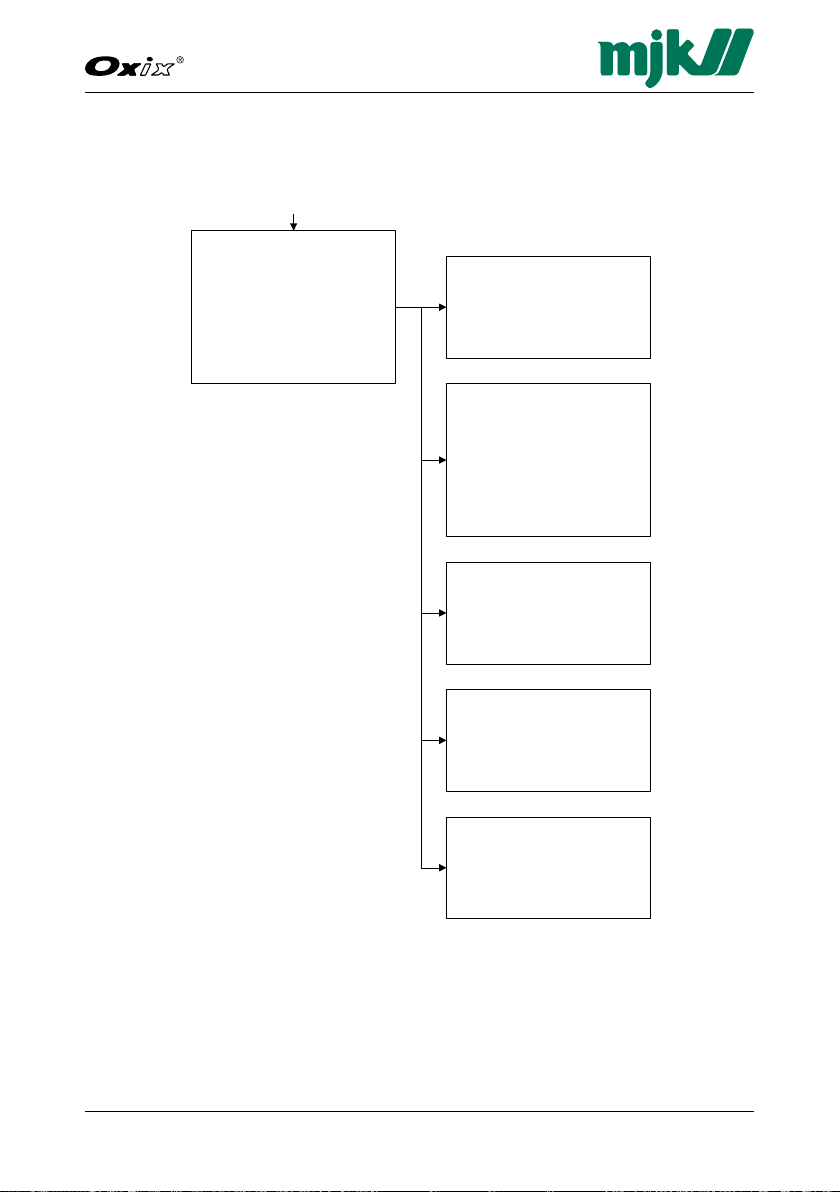
67
Dissolved Oxygen Transmitter
GB Oxix Manual 080915
FW: 841013-009, 846001-002, 841513-009
Set primary value
- - - - mg/l
Back Select >
Test primary value
Enable test
Yes
No
Back Select OK
Current
Set fixed current
Calib. current
DAC zero current
DAC top current
Back Select OK
Calib. current
- - - - uA
Back Select OK
Calibrate mA
Current
- - - - uA
Back Select OK
Set fixed current
Release mA
Minimum mA
4 mA
12 mA
20 mA
Maximum mA
Back Select OK
DAC zero current
- - - - uA
Back Select OK
DAC top current
- - - -
Back Select OK
No Hour Event Extension
1 154 0 0
2 154 0 0
3 154 0 0
4 154 0 0
Back Select >
Read eventlog
No Hour Event Extension
5 154 0 0
6 154 0 0
7 154 0 0
8 154 0 0
Back Select >
No Hour Event Extension
13 154 0 0
14 154 0 0
15 154 0 0
16 154 0 0
Back Select >
No Hour Event Extension
9 154 0 0
10 154 0 0
11 154 0 0
12 154 0 0
Back Select >
No Hour Event Extension
17 154 0 0
18 154 0 0
19 154 0 0
20 154 0 0
Back Select >
Calibrate mA
From this menu the mA reading can be calibrated against a multimeter.
Page 68

68GB Oxix Manual 080915
FW: 841013-009, 846001-002, 841513-009
Dissolved Oxygen Transmitter
Set primary value
- - - - mg/l
Back Select >
Test primary value
Enable test
Yes
No
Back Select OK
No Hour Event Extension
1 154 0 0
2 154 0 0
3 154 0 0
4 154 0 0
Back Select >
Read eventlog
No Hour Event Extension
5 154 0 0
6 154 0 0
7 154 0 0
8 154 0 0
Back Select >
Recover Factory Settings
Cancel
Back on Stock
Sensor Factory Reset
Back Select OK
Back on stock
Sensor Factory Reset
No
Yes
Back Select Ok
Modbus
Rx ok 4950
Rx CRC error 4564
Rx paritet error 4545
Rx adr. error 4566
Rx wrong id 4950
Tx count 3454
Back Select OK
Communication log
Sensor
Rx ok 4950
Test primary value
"Test primary value" is for MJK service personnel use only. It can be set to
for example 100% to test a state or condition for a given input value.
Page 69

69
Dissolved Oxygen Transmitter
GB Oxix Manual 080915
FW: 841013-009, 846001-002, 841513-009
No Hour Event Extension
1 154 0 0
2 154 0 0
3 154 0 0
4 154 0 0
Back Select >
Read eventlog
No Hour Event Extension
5 154 0 0
6 154 0 0
7 154 0 0
8 154 0 0
Back Select >
No Hour Event Extension
13 154 0 0
14 154 0 0
15 154 0 0
16 154 0 0
Back Select >
No Hour Event Extension
9 154 0 0
10 154 0 0
11 154 0 0
12 154 0 0
Back Select >
No Hour Event Extension
17 154 0 0
18 154 0 0
19 154 0 0
20 154 0 0
Back Select >
Recover Factory Settings
Cancel
Back on Stock
Sensor Factory Reset
Back Select OK
Back on stock
Sensor Factory Reset
No
Yes
Back Select Ok
Modbus
Rx ok 4950
Rx CRC error 4564
Rx paritet error 4545
Rx adr. error 4566
Rx wrong id 4950
Tx count 3454
Back Select OK
Communication log
Sensor
Rx ok 4950
Rx CRC error 4564
Rx paritet error 4545
Rx count 4950
Tx count 3454
Back Select OK
Autodetect sensor type
Use
Not in use
Back Select OK
Autodetect sensor type Mains supply frequency
Read Eventlog
View the events within a certain time frame.
Page 70

70GB Oxix Manual 080915
FW: 841013-009, 846001-002, 841513-009
Dissolved Oxygen Transmitter
Recover Factory Settings
Cancel
Back on Stock
Sensor Factory Reset
Back Select OK
Back on stock
Sensor Factory Reset
No
Yes
Back Select Ok
Modbus
Rx ok 4950
Rx CRC error 4564
Rx paritet error 4545
Rx adr. error 4566
Rx wrong id 4950
Tx count 3454
Back Select OK
Communication log
Sensor
Rx ok 4950
Rx CRC error 4564
Rx paritet error 4545
Rx count 4950
Tx count 3454
Back Select OK
Autodetect sensor type
Use
Not in use
Back Select OK
Mains supply frequency
50 Hz
60 Hz
Back Select OK
Autodetect sensor type Mains supply frequency
Recover Factory Settings
Cancel
Back on Stock
Sensor Factory Reset
Back Select OK
Back on stock
Sensor Factory Reset
No
Yes
Back Select Ok
Autodetect sensor type
Use
Not in use
Back Select OK
Mains supply frequency
50 Hz
60 Hz
Back Select OK
Autodetect sensor type Mains supply frequency
Communication log
View the Modbus and sensor communication logs. Primarily intended for
fault detection.
Back on stock
The factory settings can be re-etablished with the "Back on stock" option.
Page 71
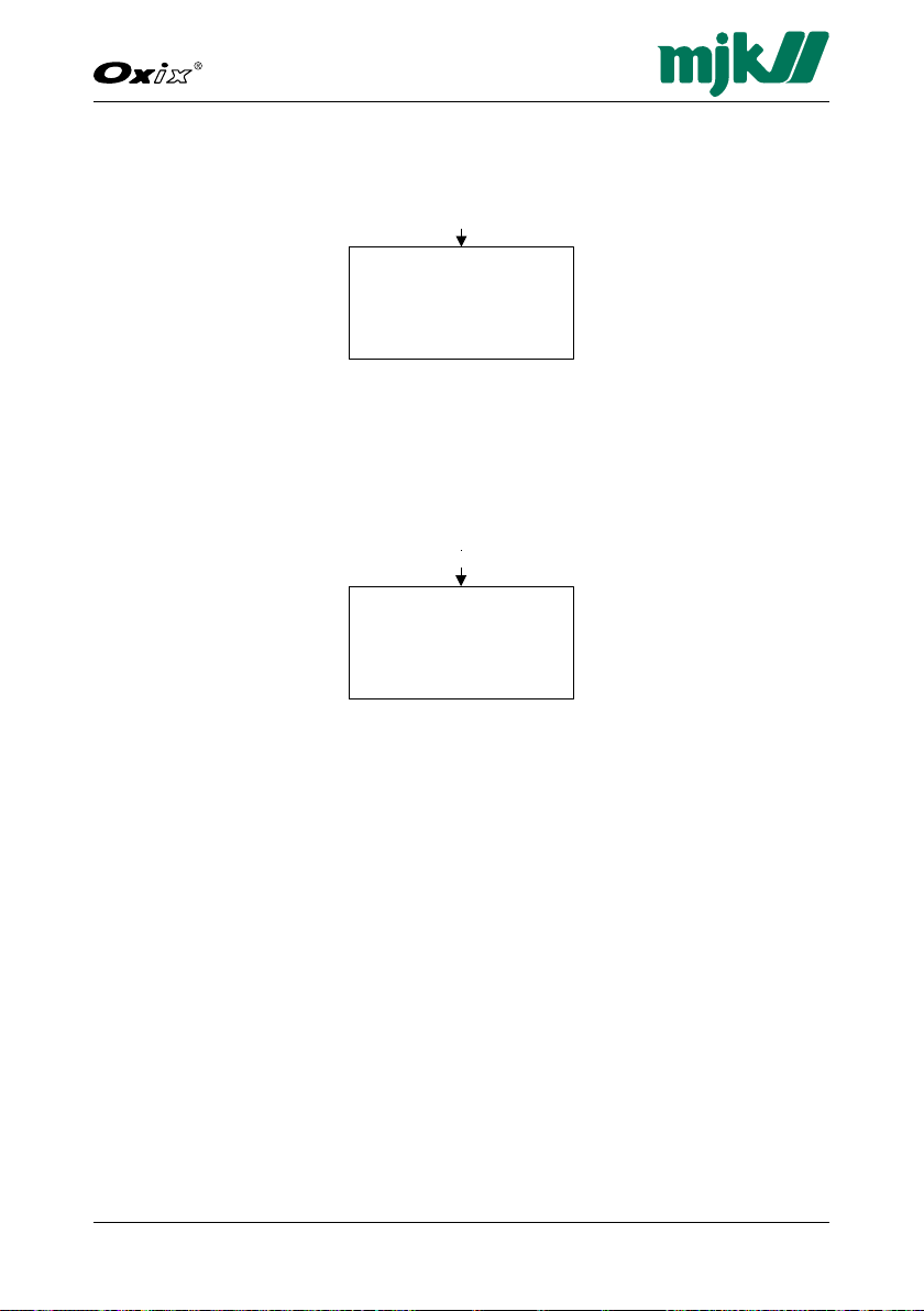
71
Dissolved Oxygen Transmitter
GB Oxix Manual 080915
FW: 841013-009, 846001-002, 841513-009
Autodetect sensor type
Use
Not in use
Back Select OK
Mains supply frequency
50 Hz
60 Hz
Back Select OK
Autodetect sensor type Mains supply frequency
Mains supply frequency
50 Hz
60 Hz
Back Select OK
Mains supply frequency
Autodetect sensor type
The option can be toggled as required. "Use" is the factory default setting.
Mains supply frequency
Select the national/local mains supply frequency: 50 Hz for Europe, Africa,
Asia, Australia and South America, and 60 Hz for USA, Canada, Mexico, Latin
America and the Carabian.
Page 72
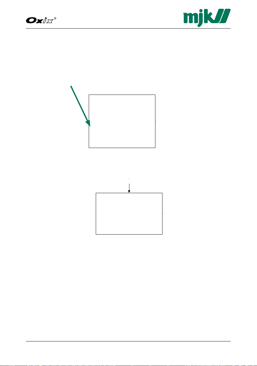
72GB Oxix Manual 080915
FW: 841013-009, 846001-002, 841513-009
Dissolved Oxygen Transmitter
Specify main Screen
Datalogger
Password
Sensor name
Converter setup
Display setup
Back Select OK
Login
Activate/deactivate
Set log interval
0020 sec
Datalogger
Select line
Linie 1 - Sensor name
Specify main Screen Converter setup
Password
Oxix1
Oxygen sat.
%
Select Set up
Main Menu
Converter Overview Menu
Set Clock
Language
Language
Set Clock
Modbus
Factory settings
Display SW version
Back Select OK
Display setup
Display Setup
The "Display Setup" menu provides options for language, clock and factory
settings, Modbus parameters and software version display.
1. Press the up/down keys to highlight the required menu line
(here: Display setup) and then press OK to select it.
2. Press the up/down keys to highlight the required optione and then press
OK.
The available options are described in detail on the following pages.
Page 73

73
Dissolved Oxygen Transmitter
GB Oxix Manual 080915
FW: 841013-009, 846001-002, 841513-009
Time Format
24 Hour
AM/PM
Back Select OK
Language
(GB) English
(US) English
Dansk
Deutsch
Español
Français
Italiano
Nederlands
Norsk
Suomalainen
Svenska
Back Select OK
Change device addresse
Scanner
Set Clock
Language
Add device
Change device addresse
Set Clock
2006-01-08 10:53:12
Back Select >
Language
The Oxix® is installed with a language package, and (GB) English is the default
language.
In the "Language" menu several national languages can be selected.
Additional languages can be added using the MJK-Field Link software program (see also page 94).
1. Chose the required language using the up/down keys up and then press
OK.
Page 74

74GB Oxix Manual 080915
FW: 841013-009, 846001-002, 841513-009
Dissolved Oxygen Transmitter
Time Format
24 Hour
AM/PM
Back Select OK
Change device addresse
Add device
Change Device addresse
Remove Device
Change Display ID No.
Back Select OK
Scanner
Set Clock
Modbus
Add device
Change device addresse
Remove device
Remove device
Set Clock
2006-01-08 10:53:12
Back Select >
Set clock
The "Set clock" menu provides setting of the built-in clock and the time format.
1. Select the date and time digits with the left/right keys and change the setting with the up/down keys.
2. Press OK and repeat step 1 for all remaining digits.
3. Press OK to save the time/clock settings.
Page 75

75
Dissolved Oxygen Transmitter
GB Oxix Manual 080915
FW: 841013-009, 846001-002, 841513-009
Cancel
Delete Log
Restore default Language
Restore factory setting
Back Select OK
Change device addresse
Device 1
Back Select OK
Add device
Change Device addresse
Remove Device
Change Display ID No.
Back Select OK
Scanner
Back
Modbus
Factory settings
Add device
Devices found
Device 1
Back Select OK
Change device addresse
Change device 1
Back Select OK
Remove device
Device 1
Back Select OK
Remove device
Change Display ID No.
1
Back Select OK
Change display ID no.
Number of Displays
1
Back Select OK
Modbus
The Oxix® is delivered with a standard Modbus RTU protocol, and up to four
Oxix® ,Connect® and/or MagFlux® units can be connected for concurrent
operation.
When several converters are to be added, you must change each converter's
device address to a unique Modbus ID address before connecting the converter to the Display Unit.
Add device
Four Oxix® Converters can be connected to one Display Unit using the RS485
interface connection. Note that only one Display Unit can be used with several
converters.
The Display Unit can easily be moved to another converters for readout and
configuration.
1. Select "Add Device", click OK and wait for the scan process to finish.
2. The found converters are finally displayed.
Page 76

76GB Oxix Manual 080915
FW: 841013-009, 846001-002, 841513-009
Dissolved Oxygen Transmitter
Change device address
To change each converter's device adress it is required that you connect the
Display Unit to each converter one by one to change each converter's device
address. If neglected, a conflict between the units will arise when the RS 485
serial loop is established.
Change for example "Device 1" to "Device 2" as follows:
1. Press OK and use the up/down keys to change "1" to "2".
2. Press OK.
The Oxix
®
converter ID is now changed to "2", and more converters can be
added to the Display Unit with the "Add Device" option.
Remove Device
If a device is to be removed from the Display Unit, proceed as follows:
1. Select the required device with the up/down keys.
2. Click OK to remove it.
The device is now removed from the Display unit and display returns to the
"Modbus" menu.
Change controller ID (display)
The display controller ID must be changed when several displays operate with
the same converter(s)
Page 77

77
Dissolved Oxygen Transmitter
GB Oxix Manual 080915
FW: 841013-009, 846001-002, 841513-009
Cancel
Delete Log
Restore default Language
Restore factory setting
Back Select OK
Display 841013-009
SW Aug 15 2008 15:14:20
Language 841513-009
Back
Factory settings
Display SW version
Display 841013-009
SW Aug 15 2008 15:14:20
Language 841513-009
Back
Display SW version
Factory settings
The "Factory settings" menu provides log deletion and resetting to factory
settings of the display unit.
1. Press the up/down keys to highlight the required option and press OK.
Important:
The data logger will be reset, and all devices will be deleted from the dis-
play Unit. This is indicated by the MJK start-up screen which is displayed
within a few seconds.
Display SW version
The "Display SW version" menu provides a read-out of the display software
(actually firmware) version, the build date and last-edited date of the the multiple languages file.
Page 78

78GB Oxix Manual 080915
FW: 841013-009, 846001-002, 841513-009
Dissolved Oxygen Transmitter
This page intentionally left blank.
Page 79
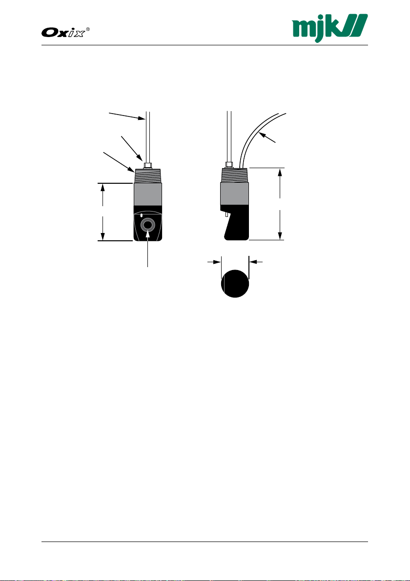
79
Dissolved Oxygen Transmitter
GB Oxix Manual 080915
FW: 841013-009, 846001-002, 841513-009
1/4” tube fitting
1 - 1/2” NPT
112 mm (4.2”)
Measuring element
1/4” tube
Cable to Oxix
Converter
130 mm (5”)
57 mm (1.9”)
10. Mechanical Dimensions
Sensor
Page 80

80GB Oxix Manual 080915
FW: 841013-009, 846001-002, 841513-009
Dissolved Oxygen Transmitter
Converter and Display Unit
162
156
144
150
186
89
83
M20
183
85
79
Page 81

81
Dissolved Oxygen Transmitter
GB Oxix Manual 080915
FW: 841013-009, 846001-002, 841513-009
Immersion Fitting
®
Immersion fitting
Oxix
order no. 155235
Wall bracket
for extension
Extension for
universal bracket
Universal
bracket
1000 mm
Oxix®
sensor
Page 82

82GB Oxix Manual 080915
FW: 841013-009, 846001-002, 841513-009
Dissolved Oxygen Transmitter
This page intentionally left blank.
Page 83

83
Dissolved Oxygen Transmitter
GB Oxix Manual 080915
FW: 841013-009, 846001-002, 841513-009
11. Maintenance
The Oxix® sensor requires no maintenance as such. It may, however, be
cleaned on a regular basis to maintain its maximum accuracy.
In very slimy environments the built-in water or air jet function may be used
with advantage.
Clean the transmitter for example once a month to begin with, until an optimal
cleaning interval can be determined.
Cleaning the sensor
1. Remove the Oxix® sensor from the liquid.
2. Clean the sensor with a soft, moist cloth and clean water. A mild detergent
or dishwashing liquid may be used.
Warning: The accuracy will deteriorate, or be completely ruined
at the worst, if the measuring optic element is scratched by
for example the use of a steel brush during cleaning.
3. Dry the sensor with a soft cloth.
4. Immerse the Oxix
least 15 minutes to stabilize the reading.
5. The cleaning intervals may need to be shortened or extended, all depending on the usage, the liquid composition and the location.
®
sensor into the liquid to be measured and leave it for at
Cleaning the converter display
When seen necessary the Oxix® converter display may be cleaned with a soft,
moist cloth.
Functional Tests
The Oxix® transmitter calibration can, if wanted, be checked from the service menu option "Sensor calibration". This option is read-only. In the unlikely
event that the unit fall out of calibration, an MJK serviceperson must be called
to fix or re-calibrate the transmitter.
Service Contract
A service contract maintains the equipment reliability and accuracy. Get in
contact with MJK’s national sales and service representatives.
Page 84

84GB Oxix Manual 080915
FW: 841013-009, 846001-002, 841513-009
Dissolved Oxygen Transmitter
This page intentionally left blank.
Page 85

85
Dissolved Oxygen Transmitter
GB Oxix Manual 080915
FW: 841013-009, 846001-002, 841513-009
Appendix A. Pop-up and Error Messages
Alarms
Current overrange Alarm - The mA connection has exceeded
the 4 - 20 mA range. For example 3,5 or
20,5 mA.
Factory reset occurred Alarm - A factory reset has occured. Some
settings have changed. Check all used settings.
High alarm Alarm - The high set point has been de-
tected.
Low alarm Alarm - The low set point has been de-
tected.
mA connection Alarm - The mA connection is not connect-
ed. If the current-out is used, deactivate mA
Current out to stop this alarm.
Errors
Calibration Error - 1. Perform calibration (see page 21)
and/or check the units and ranges (see page
52).
Eeprom write error Error - Eeprom write error. If error keeps
popping up, contact MJK.
Measuring start failed Error - Start failed. Try again.
Measuring timeout Error - Timeout. Try again.
Missing adjustment Error - The measured value has not been
entered.
Not in solid mode! Error - Calibration can only be performed
when in solid mode. Change mode and try
again.
Page 86

86GB Oxix Manual 080915
FW: 841013-009, 846001-002, 841513-009
Dissolved Oxygen Transmitter
Sensor Error - General sensor error that may also
be transferred to a relay output. Contact
MJK.
Sensor communication Error - Modbus communication errrors nor-
mally imply that a device has been moved,
added, removed or has changed status in an
illegal manner. Rearranged cables or wires
can also invoke this error message.
Reset the system to cancel the error condition.
Sensor hardware Error - Change the sensor hardware.
Sensor setting Error - Some settings are wrong or have
been changed.
Sensor supply Error - The sensor supply is too low or too
high. Check the sensor cable connection.
System Error - Internal VCC error. See the event log
for details.
System error Error - The system software is inoperable in-
cluding faulty alarm and sensor bits. Contact
MJK.
D.O. offset Error - A zero-point sensor problem. The
sensor needs a zero-point calibration.
Contact MJK.
Warnings
Sensor range exceeded Warning - The measured value is out of
range. Check the measuring range and the
measuring units.
Info
Measurement hold Info - The measurement is set on hold dur-
ing the cleaning cycle or by an error.
Sensor needs cleaning Info - The sensor needs cleaning.
System reset occurred Info - The converter has been subject to a
software or hardware reset.
Page 87

87
Dissolved Oxygen Transmitter
GB Oxix Manual 080915
FW: 841013-009, 846001-002, 841513-009
USB
Flash programming please
Programming is in progress but not finished.
wait
Flash programming done Programming is finished.
Flash crc error Cyclic redundancy check error.
Unknown command flash
Unvalid command issued.
user text
Flash address overrun A write error hos occured.
File phase error Internal USB error.
File write failure A write error hos occured.
USB protocol overrun A communication error has occured.
Page 88

88GB Oxix Manual 080915
FW: 841013-009, 846001-002, 841513-009
Dissolved Oxygen Transmitter
This page intentionally left blank.
Page 89

89
Dissolved Oxygen Transmitter
GB Oxix Manual 080915
FW: 841013-009, 846001-002, 841513-009
Appendix B. MJK-Field Link Software
The MJK-Field Link software package provides several utilities that will be
described in detail on the following pages:
PC <-> Oxix•
Saving log data•
Display firmware upgrade•
Converter firmware upgrade•
Language installation•
Important Notes!
1. Current Oxix® log data must be saved in a file before transferring and
installing new firmware. See "2. Save Log Data" overleaf.
2. Note down all display and converter settings before upgrading new
firmware.
3. The upgrade procedures below must be carried out in strict alphabetical
order. First procedure A, then B, C, D and finally E.
A. Connect a PC to the Oxix®
1. Insert the Oxix® MJK-Field Link CD-ROM into the PC's disk drive.
The MJK-Field Link opening menu will appear after a short while (see below). If the auto-run function does not execute, locate the
"MJK-Field-Link 840110-007.exe" file (or a similar file) and click "Run".
®
transmitter interconnection
Page 90

90GB Oxix Manual 080915
FW: 841013-009, 846001-002, 841513-009
Dissolved Oxygen Transmitter
2. Unscrew the four screws that hold the Display Unit.
3. Lift out the Display Unit and connect a USB mini A/B cable to the mini
USB female B connector on the rear of the front panel.
4. Connect the other end of the USB cable (max. 4.7 metres long) to the PC.
5. Select "File" in the menu bar and click "Mount USB".
If the connection is successful, a "Device Clock" window for PC and device time synchronisation is displayed (if PC and device clock were out of
sync.) along with a link status display (see below).
If the connection fails, first remove the cable and then re-connect it.
Page 91
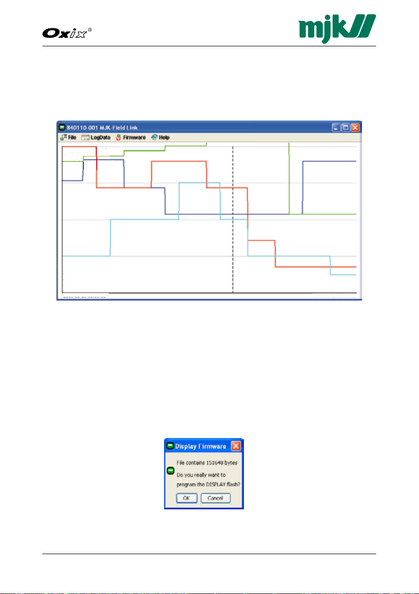
91
Dissolved Oxygen Transmitter
GB Oxix Manual 080915
FW: 841013-009, 846001-002, 841513-009
B. Save Log Data
1. Select "LogData" in the menu bar and click "Save Log to File".
2. Assign a file name, find the destination you want to save the file to, and
click "Save". Consequently the file is saved, and the contents is displayed.
C. Upgrade Display Firmware
Important: Always upgrade the display firmware before you upgrade
the converter software.
1. Select "Firmware" in the menu bar and click "Display".
2. Locate the "MJK Field FW" directory on the CD-ROM, select the 841xxxxxx.hex file (or similar 841*.hex) and click "Open".
3. Click OK when the "Display Firmware" dialogue box appears and prompts
for programming the display Flash memory.
The display unit firmware is then transferred, and the display unit is consequently programmed. Expect this process to take a few minutes.
Page 92
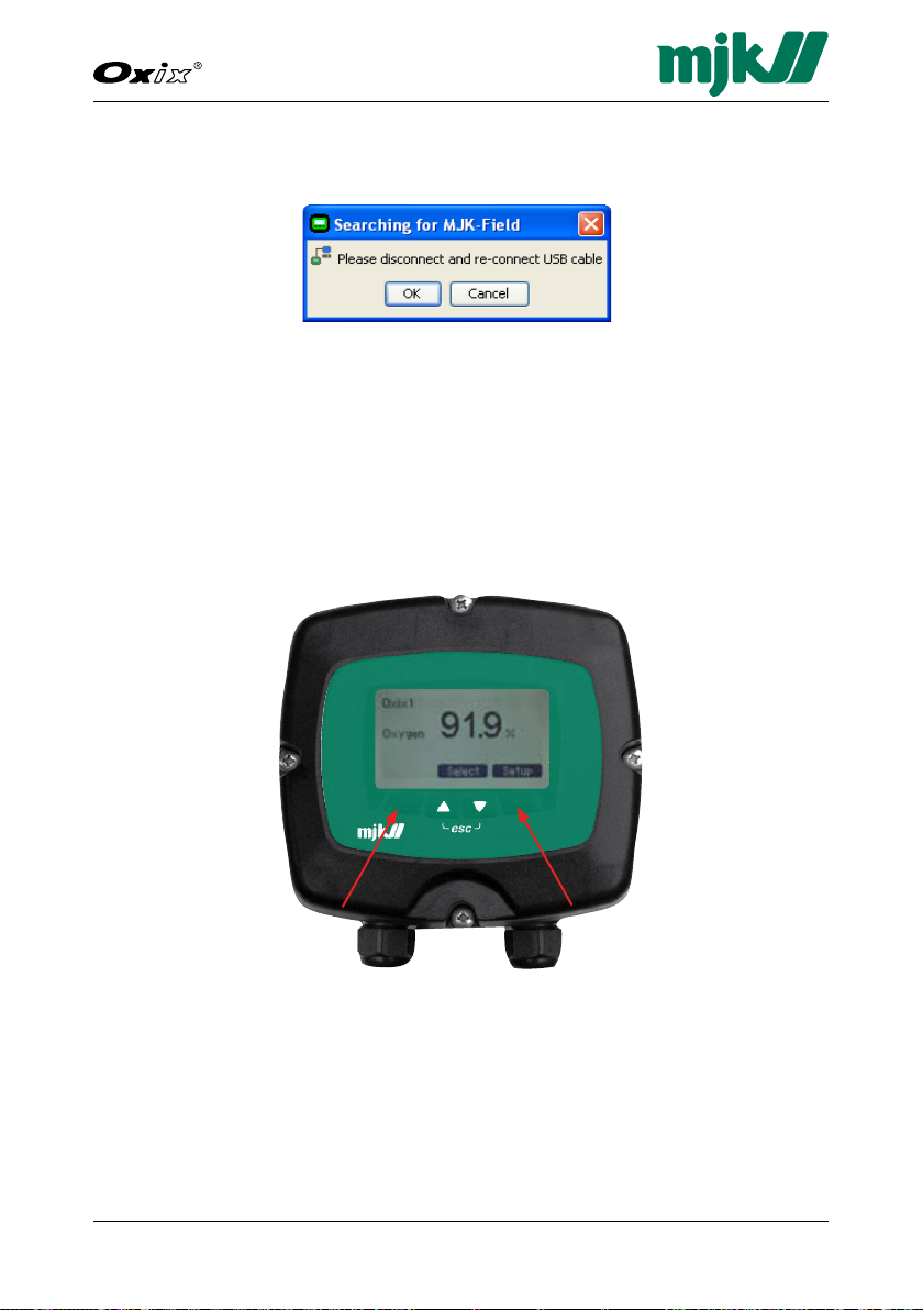
92GB Oxix Manual 080915
FW: 841013-009, 846001-002, 841513-009
Dissolved Oxygen Transmitter
4. A "Searching for MJK-Field" dialogue box then appears and prompts for
disconnecting and re-connecting the USB cable.
Do as suggested and click OK.
5. Meanwhile the Oxix
®
Display Unit restarts and displays the MJK logo, the
new link status is displayed, and the Display Unit informs that the PC is
once again connected.
Click OK on the PC and the Oxix® Display Unit to return to the Oxix®.
6. Adjust the Oxix
®
Display Unit screen contrast by pressing the two outmost
keys simultaneously (indicated by the keys) and press the up/down keys
as required.
7. Save the new setting by again pressing the two outmost keys simultaneously.
Page 93
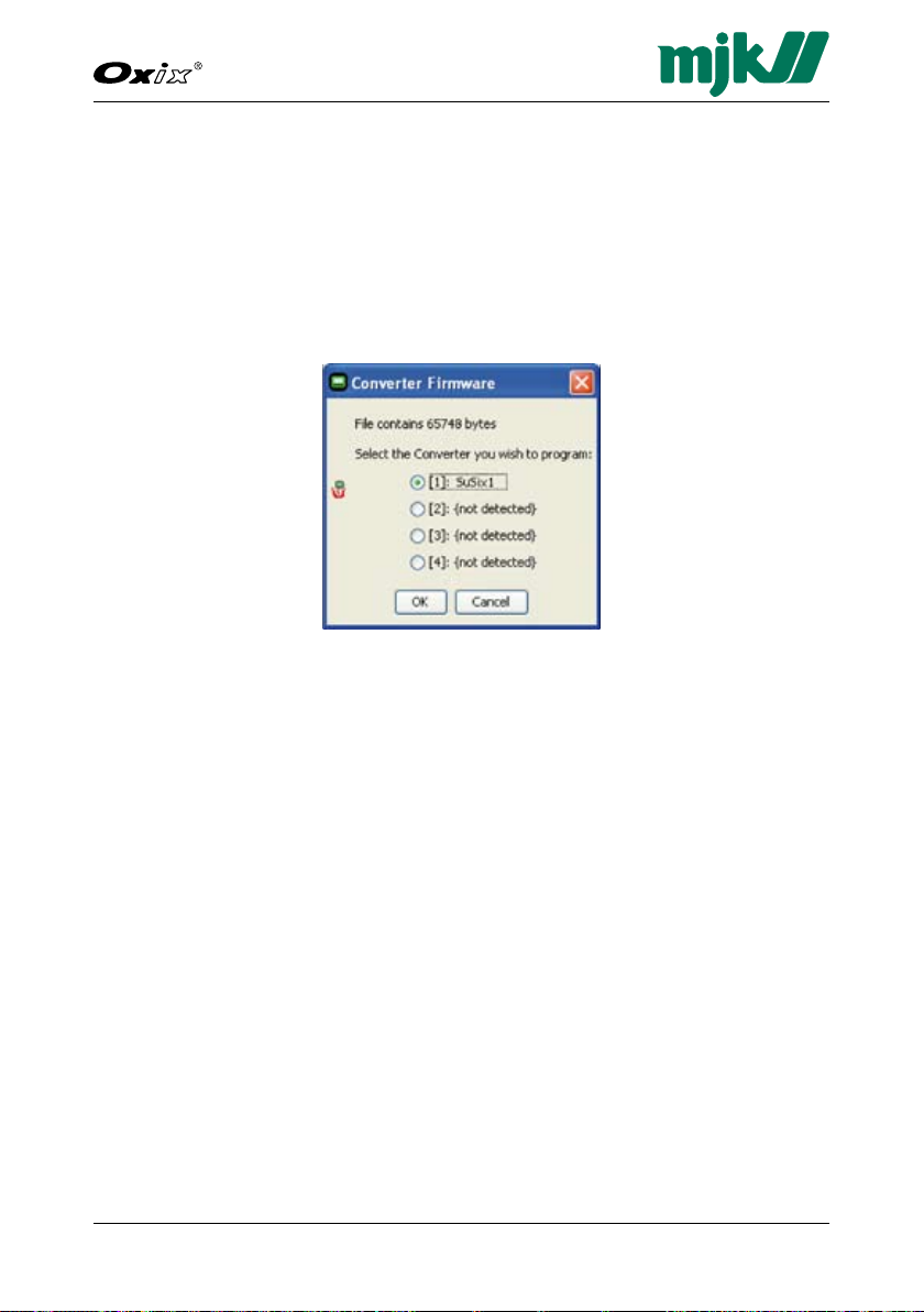
93
Dissolved Oxygen Transmitter
GB Oxix Manual 080915
FW: 841013-009, 846001-002, 841513-009
D. Upgrade Converter Firmware
1. Select "Firmware" in the menu bar and click "Converter".
2. Locate the "MJK Field FW" directory on the CD-ROM, select the "842xxxxxx.hex" file (or similar) and click "Open".
3. Select the required Oxix
"Converter Firmware" dialogue box appears and prompts for selecting the
converter to program.
The converter firmware is then transferred, and the converter Flash pro-
gramming is initiated. Expect this process to take a few minutes.
4. When the Flash programming is done, click OK on the PC and the Oxix
Display Unit to return to the Oxix® display.
5. If required you may adjust the Oxix
pressing the two outmost keys simultaneously, press the up/down keys
as required, and save the new setting by again pressing the two outmost
keys simultaneously.
®
(option 1, 2, 3 or 4) and click OK when the
®
Display Unit screen contrast by
®
Page 94

94GB Oxix Manual 080915
FW: 841013-009, 846001-002, 841513-009
Dissolved Oxygen Transmitter
Cut-out area
Frontpanel outline
Up
E. Install/Add Languages
All languages are removed during a display firmware upgrade. Consequently
the required languages must be re-installed at this stage.
1. Select "File" in the menu bar and click "Languages".
2. A dialogue appears showing the currently installed languages (none following a firmware upgrade).
You can now either add or delete the required languages.
3. Click "Add", select the required language text file (or language pack) in the
"MJK Field Display Unit text files" directory on the CD-ROM (for example
841513-008.txt) and click "Open".
4. Select for example "841500 J Europe N+W+S+US" in the "Add
Language" dialogue box (N+W+S+US = North, West, South and USA) and
click OK.
5. The languages are then transferred and loaded.
If required, you can remove one or more languages by selecting them from
the list, clicking "Delete" and "Close".
Page 95
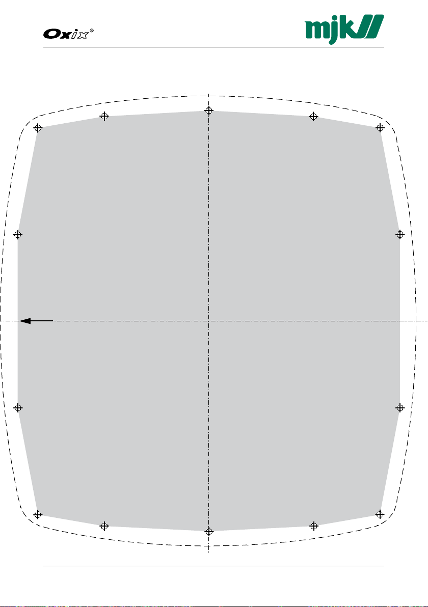
95
Dissolved Oxygen Transmitter
GB Oxix Manual 080915
FW: 841013-009, 846001-002, 841513-009
Cut-out area
Frontpanel outline
Up
Appendix C. Front Panel Cut-out Drawing
The dotted line indicates the front panel outline and measures 155 x 145 mm.
Page 96

96GB Oxix Manual 080915
FW: 841013-009, 846001-002, 841513-009
Dissolved Oxygen Transmitter
This page intentionally left blank.
Page 97
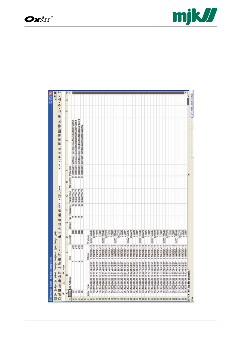
97
Dissolved Oxygen Transmitter
GB Oxix Manual 080915
FW: 841013-009, 846001-002, 841513-009
Appendix D. Log Files
The example log file shown below is the result of a CSV file from the converter
(see "Save Log Data" procedure on page 91) having been opened in with
Microsoft® Excel® spread sheet utility.
The example below illustrates a Oxix® converter being logged every 10 seconds.
The entries are described on the following page.
Page 98

98GB Oxix Manual 080915
FW: 841013-009, 846001-002, 841513-009
Dissolved Oxygen Transmitter
Index Converter ID (here four converters: 32, 33, 34 and 35)
MB Address Modbus address (here: 1, 2, 3 and 4)
Unit SI unit according to the MJK unit codes (here: 246=NTU)
MJK Unit Codes
Code no. Unit
16 GPM gallons per minute
17 l/min litres per minute
19 m
23 MGD million gallons per day
24 l/sec litres per second
28 m
57 % percent
95 mg/l milligrams per litre
96 kg/l kilograms per litre
97 g/l grams per litre
130 ft
138 l/h litres per hour
139 ppm parts per million
246 NTU Nephelometric Turbidity Units
248 FNU Formazin Nephelometric Units
249 EBC European Brewing Convention
250 FTU Formazine Turbidity Units
3
/h cubic meters per hour
3
/sec cubic meters per second
3
/h cubic feet per hour
Value ID Modbus address for flow (here: 600)
Device Type The device type (here: 9 = SuSix®)
MJK Device Type Codes
Code no. Unit
1 Display
2 MagFlux
3 Connect
4 702 Comtroller
5 Shuttle
6 pH-transmitter
7 Redox
8 Pressure transmitter
9 SuSix
10 Field log
11 Oxix
Frequency Log interval in seconds (here: 10 seconds)
Range Max Maximum value for graph
Page 99

99
Dissolved Oxygen Transmitter
GB Oxix Manual 080915
FW: 841013-009, 846001-002, 841513-009
Range Min Minimum value for graph
Precision The precision of the SI value
Column J The sensor name as entered by the operator.
Time Date and time in Central European Standard Time (CEST)
UTime The time in UNIX format. Number of seconds since
January 1, 1970.
SI Value The value in SI units (Système International d'Unités)
Page 100

100GB Oxix Manual 080915
FW: 841013-009, 846001-002, 841513-009
Dissolved Oxygen Transmitter
To plot the log file's data, proceed as follows:
1. Start Excel and open the csv log file.
2. Sort by "Index", click the "Diagram Guide" tool in the toolbar and select
the required curve or graph (see example on the next page).
 Loading...