

Operating manual
ProLab 4000
ba75646e03 12/2012
DRAFT December 10, 2012 1:25 pm
pH/ISE/Conductivity measuring instrument
with automatic sensor recognition
and electronic access control

Accuracy when
going to press
Warranty We guarantee the meter described for 3 years from the date of pur-
The use of advanced technology and the high quality standard of our
instruments are the result of a continuous development. This may
result in differences between this operating manual and your instrument. Also, we cannot guarantee that there are absolutely no errors in
this manual. Therefore, we are sure you will understand that we cannot
accept any legal claims resulting from the data, figures or descriptions.
chase.
The meter warranty covers manufacturing faults that are discovered
within the warranty period.
The warranty does not cover components that are replaced during
maintenance work, e. g. batteries.
The warranty claim extends to restoring the instrument to readiness for
use but not, however, to any further claim for damages. Improper handling or unauthorized opening of the meter invalidates any warranty
claim.
To ascertain the warranty liability, return the instrument and proof of
purchase together with the date of purchase freight paid or prepaid.
CE conformity
Radio data transmission
Copyright
SI Analytics GmbH hereby declares that the ProLab 4000 meter is in
compliance with the basic requirements and the other relevant regulations of the directive 1999/5/EC.
The EC declaration of conformity can be requested from SI Analytics
GmbH.
© 2012, SI Analytics GmbH
Reprinting - even in the form of excerpts - is only allowed with the
explicit written authorization of SI Analytics GmbH.
Printed in Germany.

ProLab 4000
KONFORMITÄTSERKLÄRUNG
DECLARATION OF CONFORMITY
DÉCLARATION DE CONFORMITÉ
Wir erklären in alleiniger
Verantwortung, dass das
Produkt
pH-/ISE-/
Leitfähigkeits-
Messgerät
ProLab 4000
auf das sich diese Erklärung
bezieht, übereinstimmt mit
den Angaben im Kapitel
We declare under our sole
responsibility that the
product
pH / ISE /
conductivity
measuring
instrument
ProLab 4000
to which this declaration
relates is in conformity with
the specifications in the
chapter
Nous déclarons sous notre
seule responsabilité que le
produit
Appareil de mesure
pour pH/ISE/
conductivité
ProLab 4000
auquel se réfère cette
déclaration est conforme aux
indications du chapitre
30. Oktober, October 30, 30 octobre 2005
AGQSF 0000-A108-01/091030
SI Analytics GmbH
Hattenbergstr. 10
D-55122 Mainz
Deutschland, Germany, Allemagne
Technische Daten
pH-/ISE-/Leitfähigkeits-Messgerät
ProLab 4000
30. Oktober 2009
ba75646e03 12/2012
3

ProLab 4000
4
ba75646e03 12/2012

ProLab 4000 Contents
ProLab 4000 - Contents
1 Overview . . . . . . . . . . . . . . . . . . . . . . . . . . . . . . . . . . . . 11
1.1 General features . . . . . . . . . . . . . . . . . . . . . . . . . . . . . . . 11
1.2 Keypad . . . . . . . . . . . . . . . . . . . . . . . . . . . . . . . . . . . . . . 12
1.3 Display . . . . . . . . . . . . . . . . . . . . . . . . . . . . . . . . . . . . . . 14
1.4 Socket field . . . . . . . . . . . . . . . . . . . . . . . . . . . . . . . . . . . 15
1.5 Automatic sensor recognition . . . . . . . . . . . . . . . . . . . . . 16
1.5.1 ID sensors . . . . . . . . . . . . . . . . . . . . . . . . . . . . . 17
1.5.2 Sensor data from ID sensors . . . . . . . . . . . . . . . 18
1.6 Electronic access control . . . . . . . . . . . . . . . . . . . . . . . . 19
2 Safety . . . . . . . . . . . . . . . . . . . . . . . . . . . . . . . . . . . . . . . 21
2.1 Authorized use . . . . . . . . . . . . . . . . . . . . . . . . . . . . . . . . 21
2.2 General safety instructions . . . . . . . . . . . . . . . . . . . . . . . 22
3 Commissioning. . . . . . . . . . . . . . . . . . . . . . . . . . . . . . . 23
3.1 Scope of delivery. . . . . . . . . . . . . . . . . . . . . . . . . . . . . . . 23
3.2 Initial commissioning . . . . . . . . . . . . . . . . . . . . . . . . . . . . 24
3.3 Connecting the power pack. . . . . . . . . . . . . . . . . . . . . . . 24
3.4 Switching on the ProLab 4000 . . . . . . . . . . . . . . . . . . . . 25
3.5 Connecting the USB mouse . . . . . . . . . . . . . . . . . . . . . . 26
3.6 Connecting sensors . . . . . . . . . . . . . . . . . . . . . . . . . . . . 26
3.6.1 Connecting an ID sensor . . . . . . . . . . . . . . . . . . 27
3.6.2 Connecting a non ID sensor. . . . . . . . . . . . . . . . 28
3.7 Connecting optional accessories . . . . . . . . . . . . . . . . . . 28
3.7.1 RS232 interface (serial port) . . . . . . . . . . . . . . . 29
3.7.2 USB-B interface (USB Device). . . . . . . . . . . . . . 31
3.7.3 USB-A interface (USB Host) . . . . . . . . . . . . . . . 32
4 Operating principles. . . . . . . . . . . . . . . . . . . . . . . . . . . 33
4.1 Operating and display elements . . . . . . . . . . . . . . . . . . . 33
4.2 File system . . . . . . . . . . . . . . . . . . . . . . . . . . . . . . . . . . . 37
4.3 Entry of numerals, letters and characters . . . . . . . . . . . . 38
4.4 Navigation . . . . . . . . . . . . . . . . . . . . . . . . . . . . . . . . . . . . 40
4.4.1 Navigation in the measured value display . . . . . 41
4.4.2 Navigation in menus. . . . . . . . . . . . . . . . . . . . . . 42
4.4.3 Navigation in dialog boxes . . . . . . . . . . . . . . . . . 44
4.4.4 Navigation in the file selection dialog box . . . . . 45
ba75646e03 12/2012
5

Contents ProLab 4000
5 Access to the meter . . . . . . . . . . . . . . . . . . . . . . . . . . . 47
5.1 Switch the meter on and off. . . . . . . . . . . . . . . . . . . . . . . 47
5.2 Login as a user . . . . . . . . . . . . . . . . . . . . . . . . . . . . . . . . 47
5.3 Password for login . . . . . . . . . . . . . . . . . . . . . . . . . . . . . . 49
5.3.1 Changing the password . . . . . . . . . . . . . . . . . . . 49
5.3.2 Assigning a password. . . . . . . . . . . . . . . . . . . . . 49
5.3.3 Forgotten the password? . . . . . . . . . . . . . . . . . . 49
5.4 Lock . . . . . . . . . . . . . . . . . . . . . . . . . . . . . . . . . . . . . . . . . 50
5.5 Access control and user rights. . . . . . . . . . . . . . . . . . . . . 51
5.5.1 Access control . . . . . . . . . . . . . . . . . . . . . . . . . . 52
5.5.2 User management and assigning user rights . . . 53
5.6 Lost your electronic key? . . . . . . . . . . . . . . . . . . . . . . . . . 55
6 System functions . . . . . . . . . . . . . . . . . . . . . . . . . . . . . 56
6.1 Overview: System settings . . . . . . . . . . . . . . . . . . . . . . . 56
6.2 Selecting the language . . . . . . . . . . . . . . . . . . . . . . . . . . 58
6.3 Selecting the country . . . . . . . . . . . . . . . . . . . . . . . . . . . . 58
6.4 Setting the date and time. . . . . . . . . . . . . . . . . . . . . . . . . 59
6.5 Selecting the channels for measured value display. . . . . 60
6.6 Interfaces for data download . . . . . . . . . . . . . . . . . . . . . . 60
6.7 Temperature . . . . . . . . . . . . . . . . . . . . . . . . . . . . . . . . . . 61
6.7.1 Temperature unit . . . . . . . . . . . . . . . . . . . . . . . . 61
6.7.2 Temperature measurement . . . . . . . . . . . . . . . . 62
6.8 Automatic stability control . . . . . . . . . . . . . . . . . . . . . . . . 63
6.9 Color assignment . . . . . . . . . . . . . . . . . . . . . . . . . . . . . . . 64
6.10 Reset . . . . . . . . . . . . . . . . . . . . . . . . . . . . . . . . . . . . . . . . 65
6.10.1 Resetting the sensor settings . . . . . . . . . . . . . . . 65
6.10.2 Resetting the system settings. . . . . . . . . . . . . . . 66
6.11 List of open windows . . . . . . . . . . . . . . . . . . . . . . . . . . . . 67
7 pH . . . . . . . . . . . . . . . . . . . . . . . . . . . . . . . . . . . . . . . . . . 69
7.1 General information . . . . . . . . . . . . . . . . . . . . . . . . . . . . . 69
7.2 Measuring the pH value. . . . . . . . . . . . . . . . . . . . . . . . . . 70
7.2.1 Preparatory activities . . . . . . . . . . . . . . . . . . . . . 70
7.2.2 Measuring. . . . . . . . . . . . . . . . . . . . . . . . . . . . . . 71
7.2.3 Measurement settings . . . . . . . . . . . . . . . . . . . . 73
7.3 Calibration . . . . . . . . . . . . . . . . . . . . . . . . . . . . . . . . . . . . 74
7.3.1 Carrying out a calibration procedure
(example: AutoCal DIN) . . . . . . . . . . . . . . 79
7.3.2 Carrying out a calibration procedure
(example: VariCal) . . . . . . . . . . . . . . . . . . . . . . . 83
7.3.3 Calibration settings and calibration data. . . . . . . 87
7.3.4 Calibration interval . . . . . . . . . . . . . . . . . . . . . . . 88
6
ba75646e03 12/2012

ProLab 4000 Contents
8 ORP voltage. . . . . . . . . . . . . . . . . . . . . . . . . . . . . . . . . . 89
8.1 General information. . . . . . . . . . . . . . . . . . . . . . . . . . . . . 89
8.2 Measuring the ORP. . . . . . . . . . . . . . . . . . . . . . . . . . . . . 90
8.2.1 Preparatory activities . . . . . . . . . . . . . . . . . . . . . 90
8.2.2 Measuring . . . . . . . . . . . . . . . . . . . . . . . . . . . . . 91
8.2.3 Measuring the relative ORP . . . . . . . . . . . . . . . . 93
8.2.4 Measurement settings . . . . . . . . . . . . . . . . . . . . 96
9 Ion concentration . . . . . . . . . . . . . . . . . . . . . . . . . . . . . 97
9.1 General information. . . . . . . . . . . . . . . . . . . . . . . . . . . . . 97
9.2 Measuring the ion concentration . . . . . . . . . . . . . . . . . . 98
9.2.1 Preparatory activities . . . . . . . . . . . . . . . . . . . . . 98
9.2.2 Measuring . . . . . . . . . . . . . . . . . . . . . . . . . . . . . 99
9.2.3 Measurement settings . . . . . . . . . . . . . . . . . . . 101
9.3 Calibration . . . . . . . . . . . . . . . . . . . . . . . . . . . . . . . . . . . 103
9.3.1 Carrying out calibration . . . . . . . . . . . . . . . . . . 106
9.3.2 Calibration data . . . . . . . . . . . . . . . . . . . . . . . . 110
9.4 Blank value correction. . . . . . . . . . . . . . . . . . . . . . . . . . 111
9.5 Reference measurement. . . . . . . . . . . . . . . . . . . . . . . . 112
9.6 Measuring with increment procedure (methods). . . . . . 113
9.6.1 Selecting the measuring method . . . . . . . . . . . 113
9.6.2 Standard addition . . . . . . . . . . . . . . . . . . . . . . . 114
9.6.3 Double standard addition . . . . . . . . . . . . . . . . . 118
9.6.4 Standard subtraction . . . . . . . . . . . . . . . . . . . . 122
9.6.5 Sample addition . . . . . . . . . . . . . . . . . . . . . . . . 126
9.6.6 Sample subtraction . . . . . . . . . . . . . . . . . . . . . 130
9.6.7 Blank value addition
(Standard addition with blank value correction) 134
ba75646e03 12/2012
10 Conductivity . . . . . . . . . . . . . . . . . . . . . . . . . . . . . . . . 139
10.1 General information. . . . . . . . . . . . . . . . . . . . . . . . . . . . 139
10.2 Measuring the conductivity . . . . . . . . . . . . . . . . . . . . . . 139
10.2.1 Preparatory activities . . . . . . . . . . . . . . . . . . . . 139
10.2.2 Measuring . . . . . . . . . . . . . . . . . . . . . . . . . . . . 140
10.2.3 Measurement settings . . . . . . . . . . . . . . . . . . . 142
10.2.4 Determining/setting the
temperature compensation . . . . . . . . . . . . . 144
10.2.5 Selecting the nonlinear
temperature compensation TC nLF . . . . . . . . . 147
10.2.6 Selecting the linear
temperature compensation TC Lin... . . . . . . . . 147
10.2.7 Selecting and adjusting the nonlinear
temperature compensation TC nLin1 . . . . . 148
10.2.8 Selecting and determining the nonlinear
temperature compensation TC nLin2 . . . . . 150
10.2.9 Selecting and determining the nonlinear
temperature compensation TC nLin3 . . . . . 152
7

Contents ProLab 4000
10.2.10 Selecting and determining the nonlinear
temperature compensation TC nLin4 . . . . . 154
10.2.11 Switching off the temperature compensation
(TC off) . . . . . . . . . . . . . . . . . . . . . . . . . . . . . . . 156
10.3 Determining the cell constant (calibration in control
standard) . . . . . . . . . . . . . . . . . . . . . . . . . . . . . . . . . . . . 157
10.3.1 Determining the cell constant (calibration) . . . . 159
10.3.2 Calibration settings and calibration data. . . . . . 160
11 Memory . . . . . . . . . . . . . . . . . . . . . . . . . . . . . . . . . . . . 161
11.1 Measurement data. . . . . . . . . . . . . . . . . . . . . . . . . . . . . 161
11.1.1 Creating and selecting a file for manually
stored measurement datasets . . . . . . . . . . . . . 162
11.1.2 Storing measurement datasets manually . . . . . 163
11.1.3 Automatically storing measurement datasets . . 164
11.1.4 Displaying and filtering stored measurement
datasets . . . . . . . . . . . . . . . . . . . . . . . . . . . . . . 166
11.1.5 Erasing measurement datasets . . . . . . . . . . . . 167
11.2 Calibration data . . . . . . . . . . . . . . . . . . . . . . . . . . . . . . . 168
11.2.1 Displaying stored calibration data. . . . . . . . . . . 168
11.2.2 Managing the calibration data. . . . . . . . . . . . . . 169
11.3 Recorder data . . . . . . . . . . . . . . . . . . . . . . . . . . . . . . . . 170
11.4 Configuration data . . . . . . . . . . . . . . . . . . . . . . . . . . . . . 170
12 Recorder . . . . . . . . . . . . . . . . . . . . . . . . . . . . . . . . . . . 171
12.1 Recording the measured value curve . . . . . . . . . . . . . . 172
12.2 Recording the curve of the measured
temperature value . . . . . . . . . . . . . . . . . . . . . . . . 173
12.3 Storing recorder data . . . . . . . . . . . . . . . . . . . . . . . . . . . 174
12.4 Displaying stored recorder data. . . . . . . . . . . . . . . . . . . 175
12.5 Settings for the recorder . . . . . . . . . . . . . . . . . . . . . . . . 176
12.5.1 Defining the recording interval . . . . . . . . . . . . . 177
12.5.2 Specifying the axes of the system
of coordinates . . . . . . . . . . . . . . . . . . . . . 177
12.5.3 Defining and activating limit values. . . . . . . . . . 179
12.5.4 Defining the colors for the
recorder representation . . . . . . . . . . . . . . . . 180
12.6 Changing the displayed axis intercept. . . . . . . . . . . . . . 181
12.7 Displaying exact measurement data at a point (cursor) 183
12.8 Deleting stored recorder data . . . . . . . . . . . . . . . . . . . . 183
13 Transmitting data . . . . . . . . . . . . . . . . . . . . . . . . . . . . 185
13.1 Printing current measurement data . . . . . . . . . . . . . . . . 185
13.2 Transmitting data (to a PC or printer) . . . . . . . . . . . . . . 185
13.2.1 RS232 interface . . . . . . . . . . . . . . . . . . . . . . . . 185
13.2.2 USB-B interface (USB Device) . . . . . . . . . . . . . 186
13.2.3 USB-A interface (USB Host). . . . . . . . . . . . . . . 187
13.2.4 Options for data transmission . . . . . . . . . . . . . . 187
8
ba75646e03 12/2012

ProLab 4000 Contents
13.3 Data backup . . . . . . . . . . . . . . . . . . . . . . . . . . . . . . . . . 188
13.3.1 Data backup by the administrator . . . . . . . . . . 188
13.3.2 Viewing backed up data. . . . . . . . . . . . . . . . . . 189
14 Configurations . . . . . . . . . . . . . . . . . . . . . . . . . . . . . . 190
14.1 Viewing a configuration . . . . . . . . . . . . . . . . . . . . . . . . . 191
14.2 Creating a new configuration . . . . . . . . . . . . . . . . . . . . 192
14.3 Loading a configuration. . . . . . . . . . . . . . . . . . . . . . . . . 193
14.4 Deleting a configuration . . . . . . . . . . . . . . . . . . . . . . . . 194
15 Maintenance, cleaning, disposal. . . . . . . . . . . . . . . . 195
15.1 Maintenance . . . . . . . . . . . . . . . . . . . . . . . . . . . . . . . . . 195
15.2 Cleaning . . . . . . . . . . . . . . . . . . . . . . . . . . . . . . . . . . . . 196
15.3 Disposal . . . . . . . . . . . . . . . . . . . . . . . . . . . . . . . . . . . . 196
16 What to do if... . . . . . . . . . . . . . . . . . . . . . . . . . . . . . . . 197
16.1 pH and ORP measurement. . . . . . . . . . . . . . . . . . . . . . 197
16.2 Ion selective measurement . . . . . . . . . . . . . . . . . . . . . . 199
16.3 Conductivity measurement . . . . . . . . . . . . . . . . . . . . . . 200
16.4 General errors. . . . . . . . . . . . . . . . . . . . . . . . . . . . . . . . 201
17 Technical Data. . . . . . . . . . . . . . . . . . . . . . . . . . . . . . . 203
17.1 General data . . . . . . . . . . . . . . . . . . . . . . . . . . . . . . . . . 203
17.2 Measuring ranges, resolution, accuracy . . . . . . . . . . . . 206
17.2.1 Temperature. . . . . . . . . . . . . . . . . . . . . . . . . . . 206
17.2.2 pH/ORP . . . . . . . . . . . . . . . . . . . . . . . . . . . . . . 206
17.2.3 ISE . . . . . . . . . . . . . . . . . . . . . . . . . . . . . . . . . . 207
17.2.4 Conductivity . . . . . . . . . . . . . . . . . . . . . . . . . . . 207
18 Lists . . . . . . . . . . . . . . . . . . . . . . . . . . . . . . . . . . . . . . . 209
Appendix . . . . . . . . . . . . . . . . . . . . . . . . . . . . . . . . . . . 219
A.19 Firmware update . . . . . . . . . . . . . . . . . . . . . . . . . . . . . . 219
A.20 Menus . . . . . . . . . . . . . . . . . . . . . . . . . . . . . . . . . . . . . . 221
A.20.1 Main menu . . . . . . . . . . . . . . . . . . . . . . . . . . . . 221
A.20.2 pH sensor menu. . . . . . . . . . . . . . . . . . . . . . . . 223
A.20.3 U sensor menu . . . . . . . . . . . . . . . . . . . . . . . . . 224
A.20.4 dU sensor menu. . . . . . . . . . . . . . . . . . . . . . . . 224
A.20.5 ISE sensor menu . . . . . . . . . . . . . . . . . . . . . . . 225
A.20.6 Cond sensor menu. . . . . . . . . . . . . . . . . . . . . . 226
ba75646e03 12/2012
9

Contents ProLab 4000
10
ba75646e03 12/2012
ProLab 4000 Overview
1
2
4
3
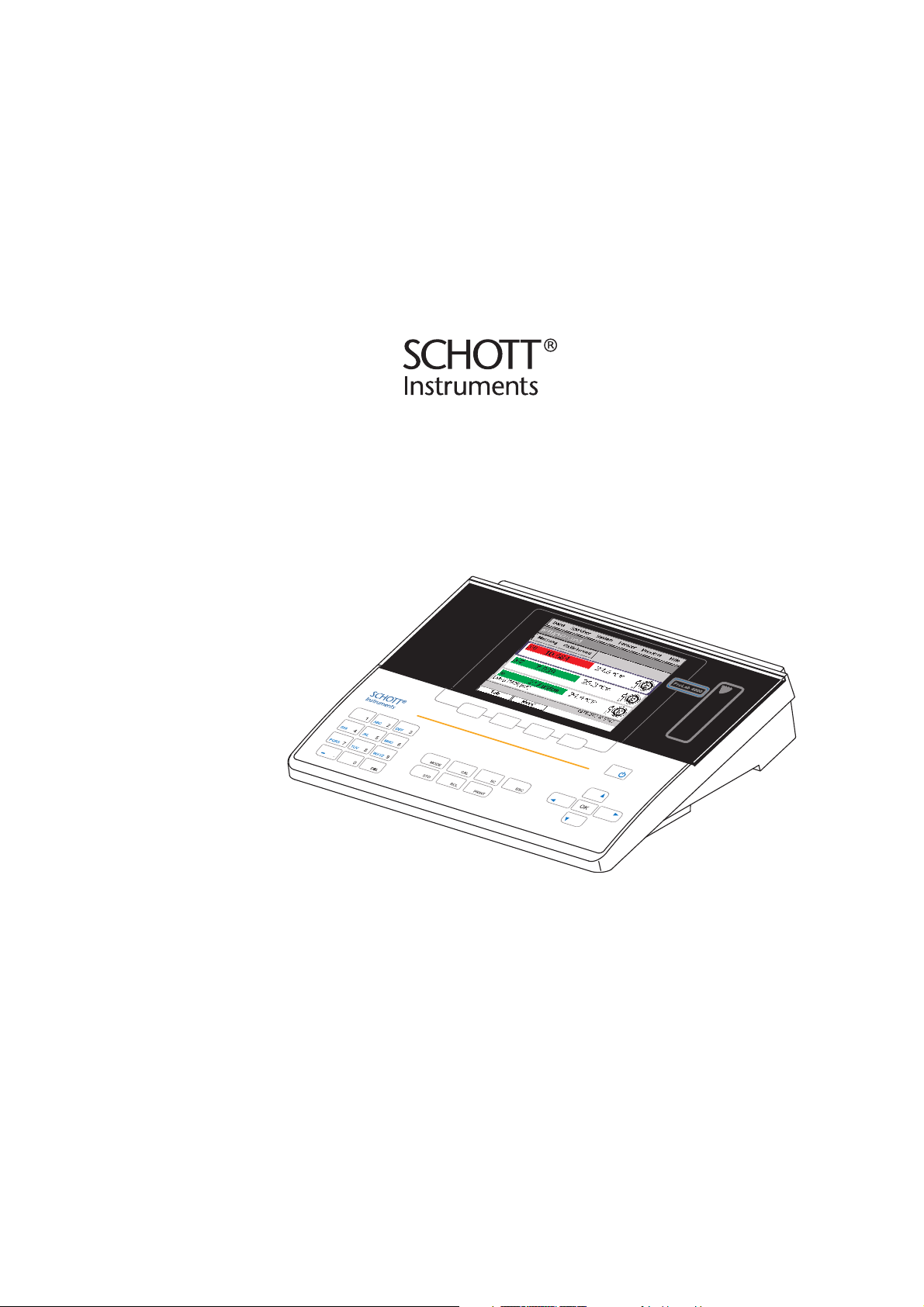
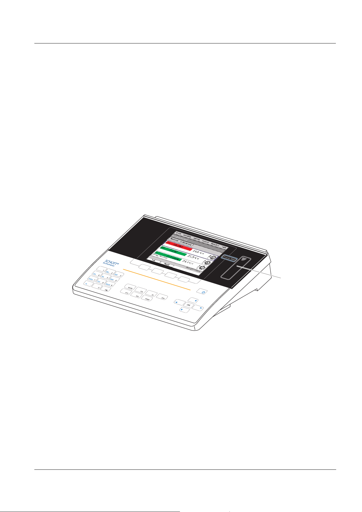
1Overview
1.1 General features
The ProLab 4000 precision meter enables you to
perform pH, ORP, conductivity and ion-selective measurements rapidly
and reliably.
Das ProLab 4000 provides the maximum degree of ease of use, reliability and, above all, measuring certainty for all applications.
The proven calibration procedures, and
stability control function (SC) and the sensor recognition function support your work with the meter.
In addition, the ProLab 4000 provides an electronic access control.
Documented measurement data is thus automatically assigned to a
user.
ba75646e03 12/2012
1 Keypad
2 Display
3 Reader field for electronic access con-
trol
4 Jack field
11
Overview ProLab 4000
123
456
789
0
.
ABC DEF
GHI JKL MNO
PQRS TUV WXYZ
_
SCMODE
DEL
STO
ESC
PRINT
CAL
RCL
OK
MODE
CAL
SC
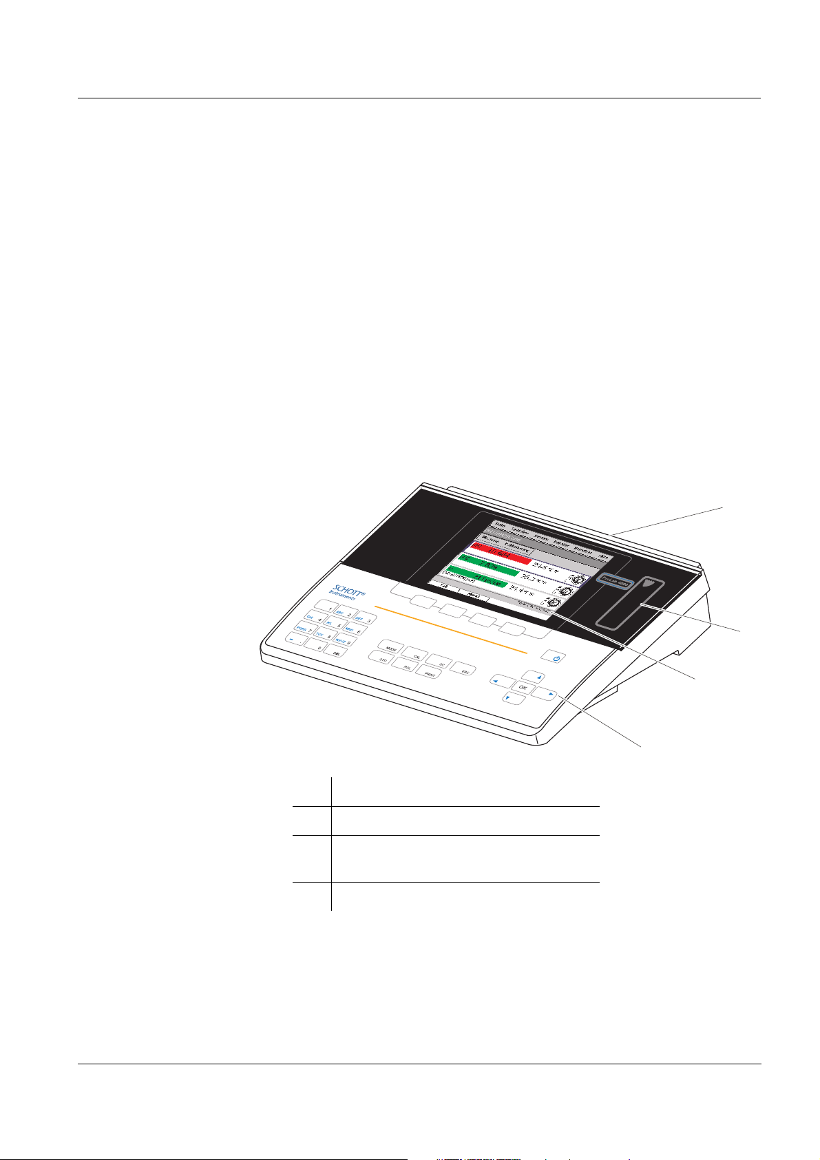
1.2 Keypad
Keys with dedicated
functions
Keys with changing
functions
(softkeys)
Key functions
Keys with dedicated functions are labeled on the meter.
In this operating manual, they are identified by the key labeling, bold letters and angle brackets <..> .
Keys with changing functions are not labeled; the currently assigned
function is shown on the display instead. In this operating manual,
these keys are identified by the displayed softkey function, bold letters
and angle brackets [..] .
The key symbol (e.g. <OK> or [OK]) generally means you should press
a key in this operating manual.
<On/Off> Switch the meter on/off
<MODE> Select measured parameter
<CAL> Call up calibration procedure
<SC> Switch on or off the stability control func-
tion manually.
<> Reduce values, Scroll
Move in the menu
12
<> Increase values, Scroll
Move in the menu
<> Reduce values, Scroll
Move in the menu
<> Increase values, Scroll
Move in the menu
ba75646e03 12/2012
ProLab 4000 Overview
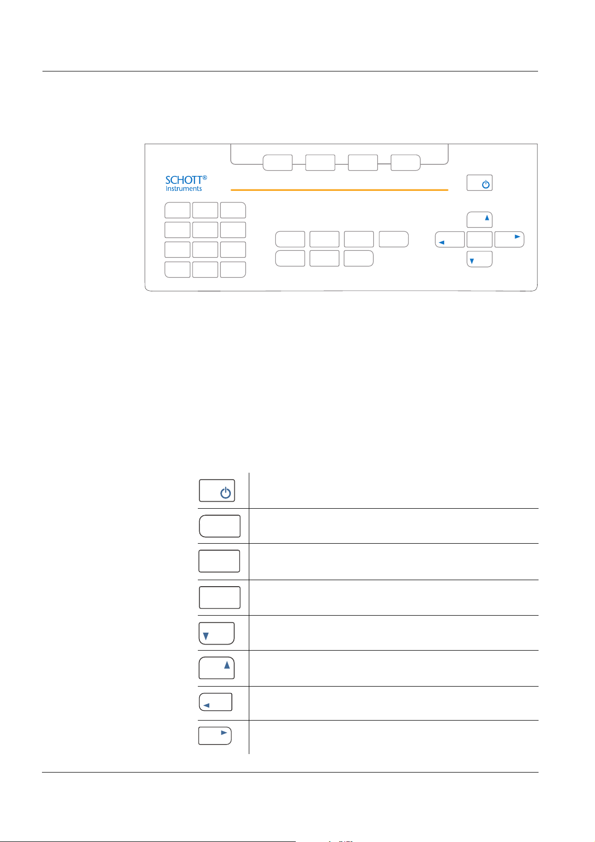
OK
ESC
STO
RCL
PRINT
7
PQRS
7
PQRS
.
_
LDE
<OK> Confirm entries
<ESC> Return to higher menu level /
Cancel inputs
<STO> Store a measured value
<RCL> Open the menu for stored measured val-
ues
<PRINT> Print or output data to an interface (serial
RS232, USB-A (USB Host) or USB-B USB
Device))
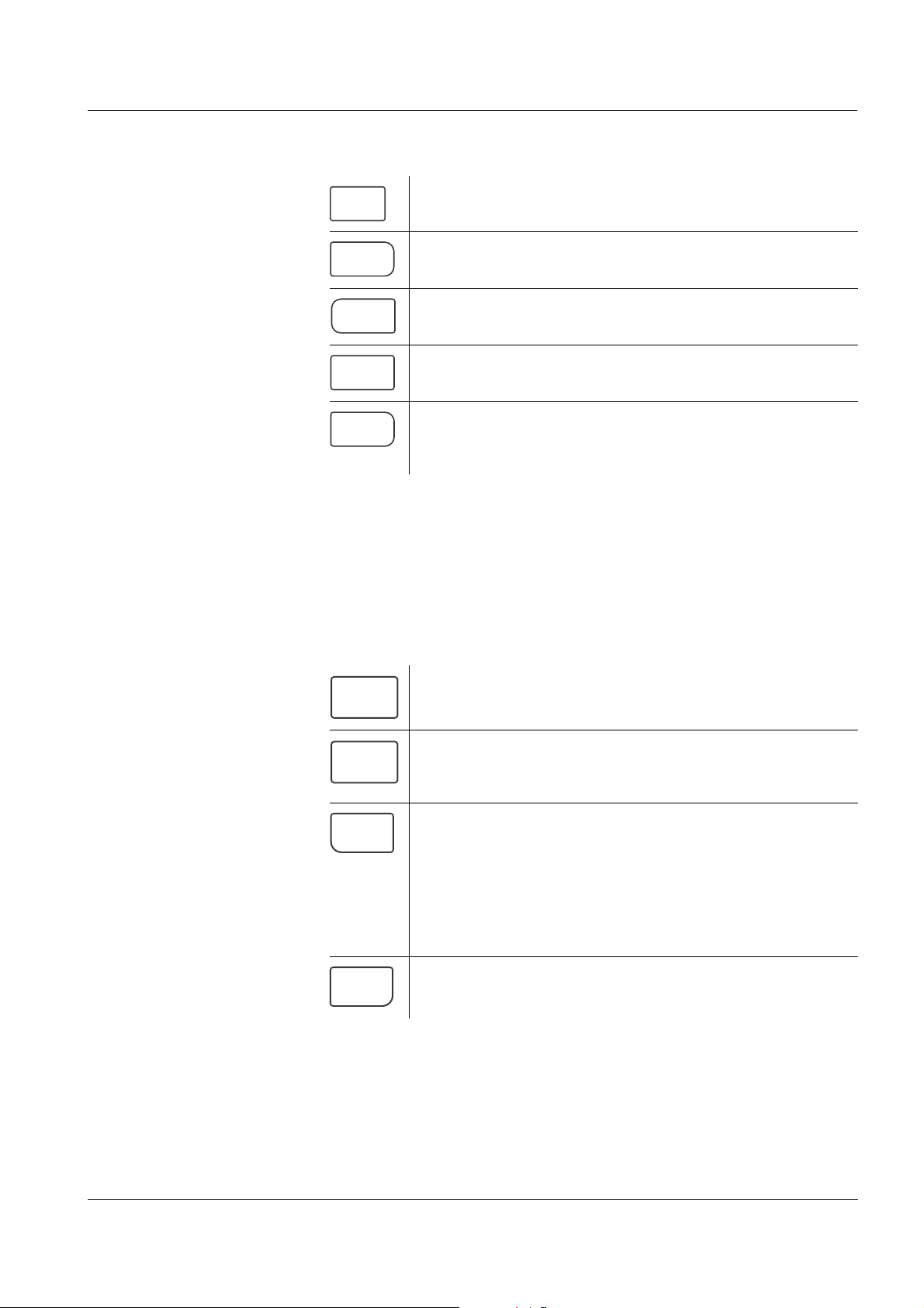
Alphanumeric keypad The keys of the alphanumeric keypad are used to enter numerals
(<0...9>), letters (<A...Z>) and characters (<- .>). The keys of the alpha-
numeric keypad only have a function if the ProLab 4000 is waiting for a
character to be entered, e.g. in input fields for the ID during manual
storage.
<0...9> Press the key once.
The numeral is displayed in the input field
<A...Z> Press the key several times if necessary
until the required letter is displayed in the
input field
<- .> Depending on the input field, the keys is
automatically interpreted as a minus sign
or decimal point.
Numeral input field:
Cursor is in front of the first digit: Minus.
Cursor is behind a numeral: Decimal point
<DEL> Deletes the character left of the cursor
ba75646e03 12/2012
13
Overview ProLab 4000
1
2
3
10
9
8
7
6
5
11
4
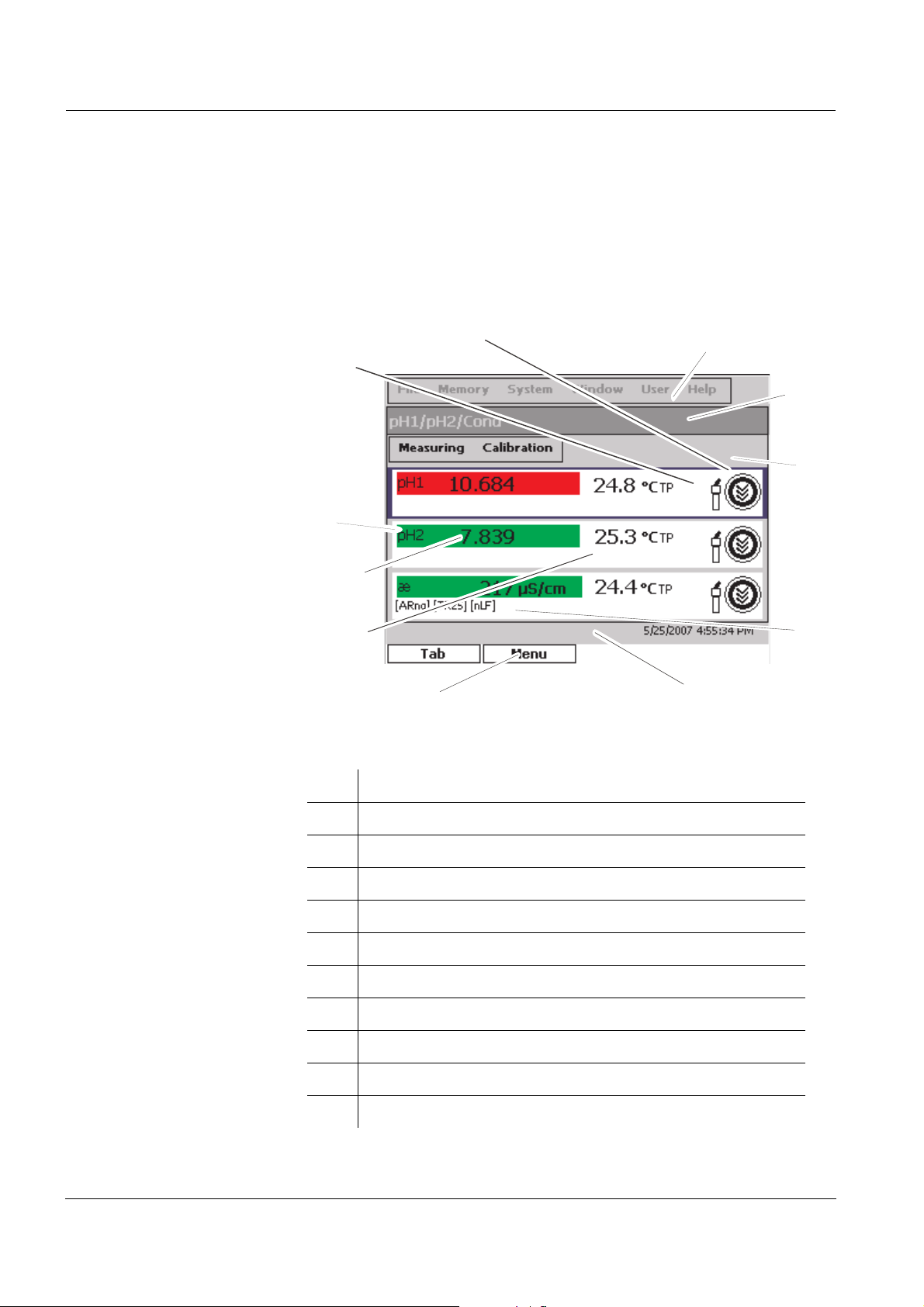
1.3 Display
The graphic color display can display three measured parameters and
the current temperature value for each measured parameter at the
same time.The illumination enables to read the display even in the
darkness.
Elements:
1 Menu line (main menu)
2 Sensor window (title bar)
3 Menu line (sensor menu)
4 Status line
5 Info line with date and time, info or action text
6 Key assignment with changing functions (softkeys)
7 Temperature display
8 Measured value (with unit)
9 Measured parameter
10 ID sensor symbol
11 CalClock
14
ba75646e03 12/2012
ProLab 4000 Overview
pH/U/ISE
Probe 2
Cond
Probe
TP 2
Ref 2
TP 1
Ref 1
pH/U/ISE
Probe 1
USB Device
USB Host
RS232
9V/DC
input
1 2
3
4
10
11
6
7
5
9
8
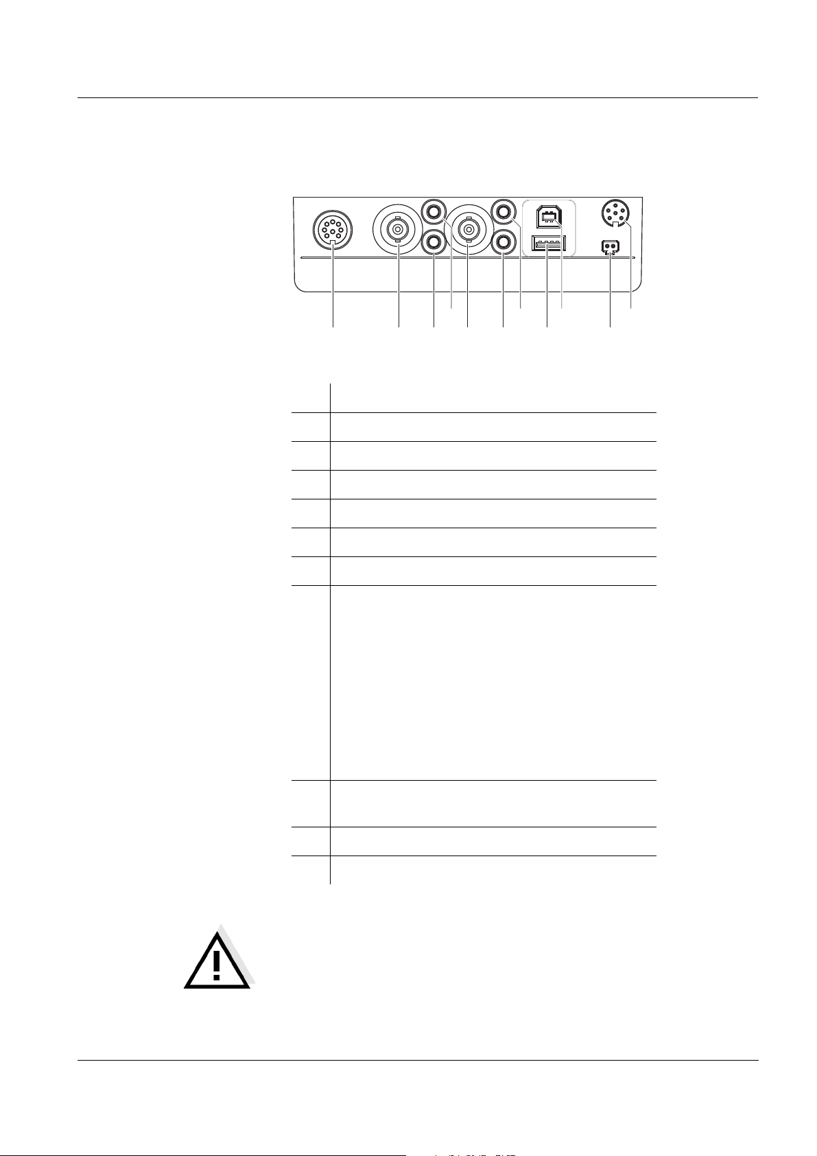
1.4 Socket field
Connections:
1 Conductivity measuring cell (Cond Probe)
2 pH/ISE/ORP electrode (pH/U/ISE Probe 2)
3 Reference electrode (Ref 2)
4 Temperature sensor (TP 2)
5 pH/ISE/ORP electrode (pH/U/ISE Probe 1)
6 Reference electrode (Ref 1)
7 Temperature sensor (TP 1)
8 USB Host interface, e.g. for
– the USB mouse,
– a USB printer,
– a USB hub,
– a USB keyboard,
– a USB storage,
– a USB card reader or
– other USB devices
9 USB interface (USB Device),
e.g. for a PC.
10 Power pack (9V/DC input)
11 RS232 interface (RS232)
ba75646e03 12/2012
CAUTION
Only connect sensors to the meter that cannot return any voltages or currents that are not allowed (> SELV and > current circuit
with current limiting).
Almost all sensors - in particular SI Analytics sensors - fulfill
these conditions.
15
Overview ProLab 4000
DIN
BNC
1.5 Automatic sensor recognition
The automatic sensor recognition function enables
to operate a sensor with different meters without recalibrating
to operate different sensors with one meter without recalibrating
to assign measurement data to a sensor
– measurement datasets are always downloaded to the interface
with the sensor type and sensor series number.
– measurement datasets are always stored together with the sen-
sor type and sensor series number.
to assign calibration data to a sensor
– calibration data is always downloaded to the interface with the
sensor type and sensor series number.
the automatic activation of the cell constants for conductivity sen-
sors
to hide menus that are not relevant for this sensor
To be able to use the automatic sensor recognition function a meter is
required that supports the automatic sensor recognition (e.g.
ProLab 4000), and a sensor (ID sensor) that is suitable for sensor recognition.
In every ID sensor, sensor data is stored that clearly identifies the sensor.
The sensor data is sent to the meter automatically via radio communication and used for sensor identification there.
16
Note
With the ProLab 4000 you can also operate non ID sensors. Then,
however, you cannot use the advantages of the sensor recognition
function.
ba75646e03 12/2012
ProLab 4000 Overview
ID sensor
symbol
1.5.1 ID sensors
SI Analytics GmbH ID sensors support the automatic sensor recognition function. Their sensor designation has the addition "ID", e.g. BlueLine A 161 1M-BNC-ID electrode.
Note
Information on available ID sensors is given on the Internet or directly
by SI Analytics.
ID sensors connected to the ProLab 4000 meter can be recognized by
the ID sensor symbol on the display.
ba75646e03 12/2012
17
Overview ProLab 4000
1.5.2 Sensor data from ID sensors
ID sensors transmit the following sensor data to the meter:
SENSOR ID
– Sensor type
– Sensor series number
Calibration data
– Calibration date
– User (having carried out the last calibration procedure)
– Calibration characteristics
– Calibration interval
– Selected buffer set (pH electrodes only)
– Last cell constant (conductivity measuring cell only)
Measurement settings (conductivity measuring cells only)
– Specified reference temperature
– Adjusted temperature coefficient
– Adjusted TDS factor
The calibration data is updated in the ID sensor after each calibration
procedure. A message is displayed while data is updated in the sensor.
Note
While data is updated in the sensor, the sensor must not be disconnected because otherwise the calibration data will not be completely
transmitted. The sensor will then have no valid calibration.
Note
If non-ID sensors are used, the calibration data from the meter is used
and also stored in the meter.
18
ba75646e03 12/2012
ProLab 4000 Overview
Reader field for
the electronic
key
1.6 Electronic access control
The ProLab 4000 always documents measurement and calibration
data together with a user name.
Thus all measurement data is assigned to the user, in compliance with
GLP.
The user name is easily and safely transmitted to the ProLab 4000 via
an electronic key. Each electronic key in the form of a keyring pendant
contains a key number and a user name. The key number and user
name are read by the meter via a contactless radio data connection.
The meter checks the access authorization for the user name. Measurements with an electronic key are only possible if the key number
and user name is registered in the meter. The measuring data is then
documented along with the registered user name.
ba75646e03 12/2012
If the user name of an electronic key is not registered in the meter,
access to the meter with this electronic key is denied.
If access to the meter is anonymous (no password, no electronic key
required), all data are documented with the user name, Anonymous.
By labeling the measurement data with Anonymous, this data can be
excluded from the GLP-compliant documentation.
19

Overview ProLab 4000
20
ba75646e03 12/2012
ProLab 4000 Safety
2 Safety
This operating manual contains basic instructions that you must follow
during the commissioning, operation and maintenance of the meter.
Consequently, all responsible personnel must read this operating manual before working with the measuring system. The operating manual
must always be available within the vicinity of the meter.
Target group The meter was developed for work in the laboratory.
Thus, we assume that, as a result of their professional training and
experience, the operators will know the necessary safety precautions
to take when handling chemicals.
Safety instructions The individual chapters of this operating manual use the following
safety instruction to indicate various types of danger:
CAUTION
indicates instructions that must be followed precisely in order to
avoid the possibility of slight injuries or damage to the meter or
the environment.
Further notes
Note
indicates notes that draw your attention to special features.
Note
indicates cross-references to other documents, e.g. operating manuals.
2.1 Authorized use
This meter is authorized exclusively for measurements of the pH, ORP,
conductivity and ion-selective measurements in the laboratory.
The technical specifications as given in chapter 17 T
(page 203) must be observed. Only the operation and running of the
meter according to the instructions given in this operating manual is
authorized. Any other use is considered unauthorized.
ECHNICAL DATA
ba75646e03 12/2012
21

Safety ProLab 4000
2.2 General safety instructions
This instrument is built and inspected according to the relevant guidelines and norms for electronic measuring instruments (see page 203).
It left the factory in a safe and secure technical condition.
Function and
operational safety
The smooth functioning and operational safety of the meter can only be
guaranteed if the generally applicable safety measures and the specific
safety instructions in this operating manual are followed during operation.
The smooth functioning and operational safety of the meter can only be
guaranteed under the environmental conditions that are specified in
chapter 17 T
ECHNICAL DATA (page 203).
If the instrument was transported from a cold environment to a warm
environment, the formation of condensate can lead to the faulty functioning of the instrument. In this event, wait until the temperature of the
meter reaches room temperature before putting the meter back into
operation.
Safe operation If safe operation is no longer possible, the meter must be taken out of
service and secured against inadvertent operation!
Safe operation is no longer possible if the meter:
has been damaged in transport
has been stored under adverse conditions for a lengthy period of
time
Obligations of the
purchaser
is visibly damaged
no longer operates as described in this manual.
If you are in any doubt, please contact the supplier of the meter.
The purchaser of this meter must ensure that the following laws and
guidelines are observed when using dangerous substances:
EEC directives for protective labor legislation
National protective labor legislation
Safety regulations
Safety datasheets of the chemical manufacturers.
22
ba75646e03 12/2012

ProLab 4000 Commissioning
3 Commissioning
3.1 Scope of delivery
ProLab 4000 laboratory meter
Power pack
4 batteries 1.5 V Micro type AAA
1 electronic administrator key (as keyring pendant)
1 electronic user key (as keyring pendant)
Cover
USB cable (Z875)
USB mouse
CD-ROM with USB driver for the PC
Operating manual
ba75646e03 12/2012
23
Commissioning ProLab 4000
3.2 Initial commissioning
Perform the following activities:
Insert the batteries (see page 195)
Connect the power pack (see page 24).
Switch on ProLab 4000 (see page 25).
Connect the USB mouse (see page 26)
Setting the language (see page 58)
Set the date and time (see page 59)
Set up the access authorization for user keys (see page 53)
Connect the sensor (see page 27).
3.3 Connecting the power pack
The power pack supplies the meter with low voltage (9 V DC).
The batteries are only used to buffer the system time if the power supply is interrupted.
CAUTION
The line voltage at the operating site must lie within the input
voltage range of the original power pack (see page 203).
CAUTION
Use original power packs only (see page 203).
1 Insert the plug into the socket of the meter.
2 Connect the original power pack to an easily accessible power
outlet.
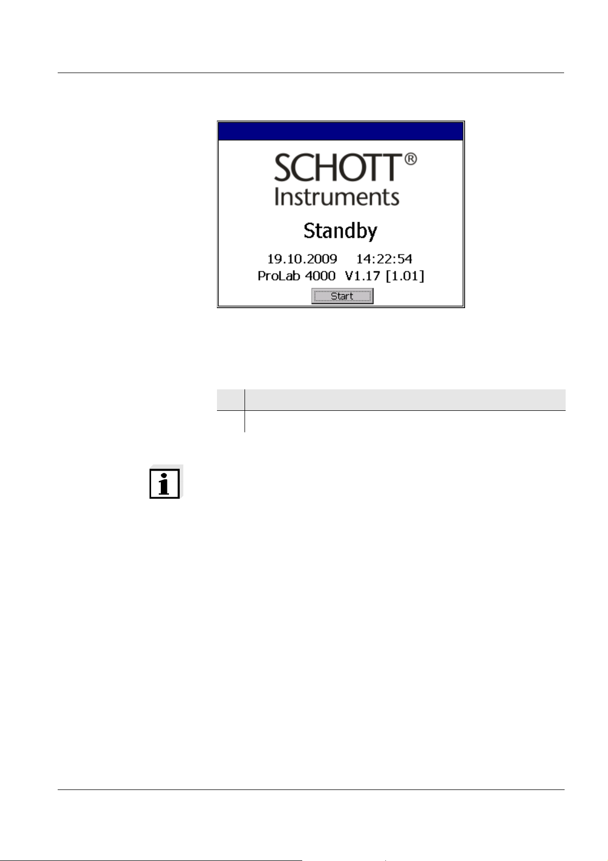
The self-test, meter designation, software version and subsequently the Standby display appear.
24
ba75646e03 12/2012
ProLab 4000 Commissioning
3.4 Switching on the ProLab 4000
The ProLab 4000 indicates the Standby display.
1 Switch the meter on with <OK>.
2 The meter switches itself on. The Login dialog box is displayed.
Note
The default password for the administrator is "00001".
For your safety, change it as soon as possible (see page 49).
ba75646e03 12/2012
25
Commissioning ProLab 4000
3.5 Connecting the USB mouse
You can connect the USB mouse included in the scope of delivery to
the USB-A USB Host interface of the ProLab 4000. Thus the
ProLab 4000 can be operated like a PC.
3.6 Connecting sensors
If an ID sensor is connected, the ProLab 4000 recognizes the sensor
type, sensor name and series number of the sensor.
If the ID sensor cannot be automatically assigned to a channel, the
Automatic sensor recognition window prompts the manual assignment.
26
Note
 wrong assignment of ID sensors to channels can be corrected by
reassigning the sensors, e.g. after
Switching off, then on the meter
Disconnecting, then reconnecting all ID sensors.
ba75646e03 12/2012
ProLab 4000 Commissioning
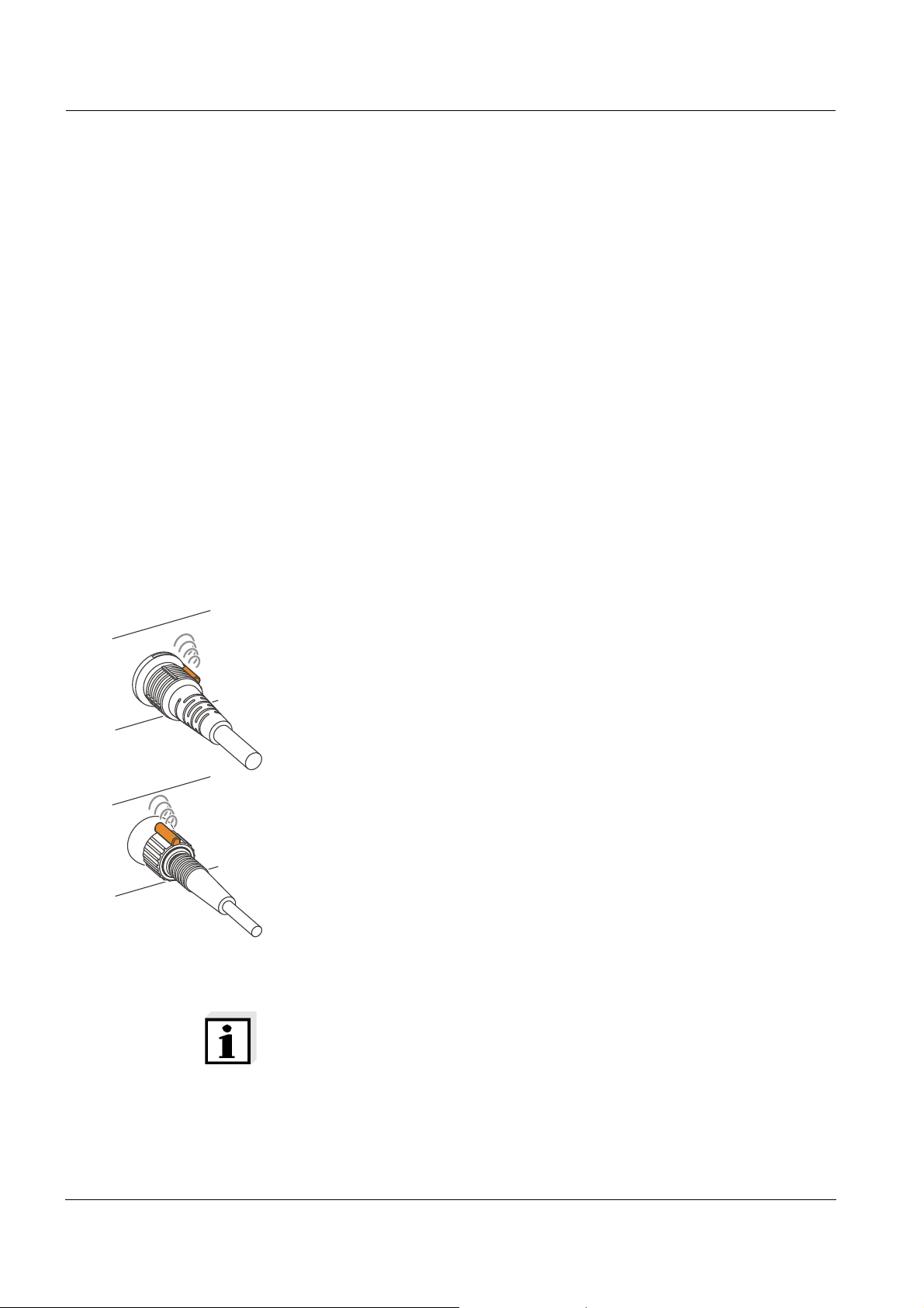
3.6.1 Connecting an ID sensor
ID sensor with
temperature sensor
ID sensor without
temperature sensor
1 Connect the temperature sensor of the ID sensor to the socket.
2 Connect the ID sensor to the socket of the meter.
The sensor is automatically assigned.
The channel to which is was assigned shows the measurement
data of the sensor.
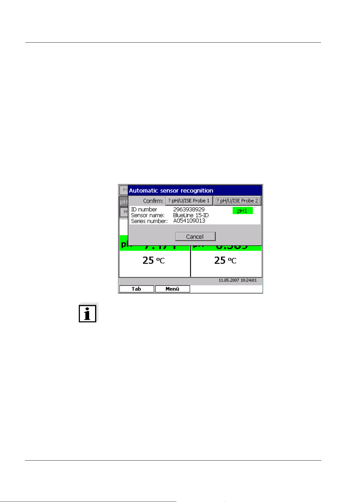
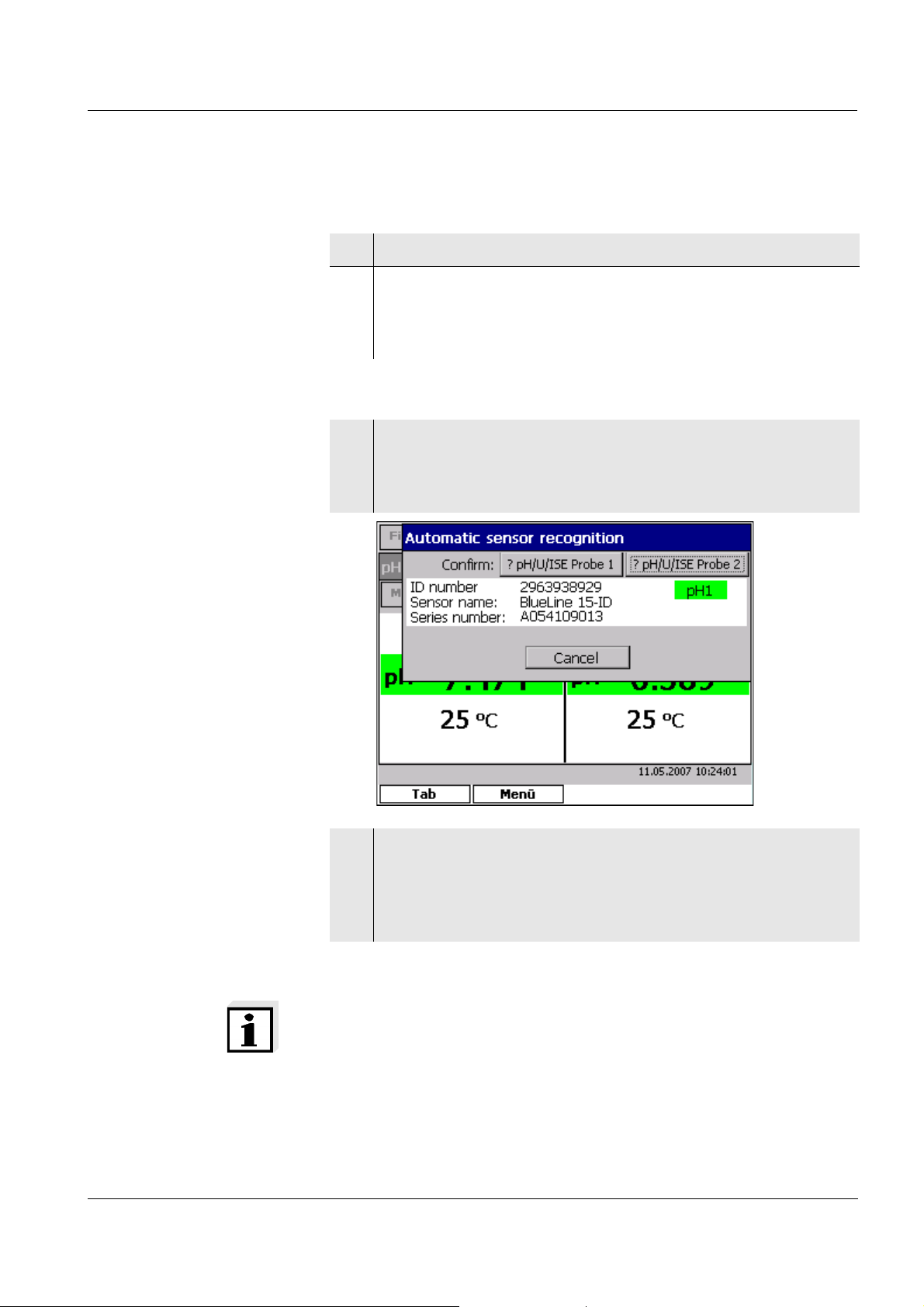
1 Connect the ID sensor to the socket of the meter.
As soon as the meter has recognized the ID sensor, the Auto-
matic sensor recognition window appears with the sensor
name and series number.
ba75646e03 12/2012
2 Assign the sensor that was recognized to a channel with pH/U/
ISE Probe 1 or pH/U/ISE Probe 2.
As soon as a sensor was assigned to a channel, the assignment is completed and the Automatic sensor recognition is
closed again.
Note
The manual assignment of a sensor to a channel is stored in the
meter. The next time the meter is switched on while ID sensors are
connected, the last assignment of the sensor is displayed and can be
confirmed with <OK>.
27
Commissioning ProLab 4000
3.6.2 Connecting a non ID sensor
1 Connect the sensor and if necessary, temperature sensor to a
socket.
The relevant channel shows the measurement data of the sensor.
2 Prior to measuring:
Calibrate the sensor.
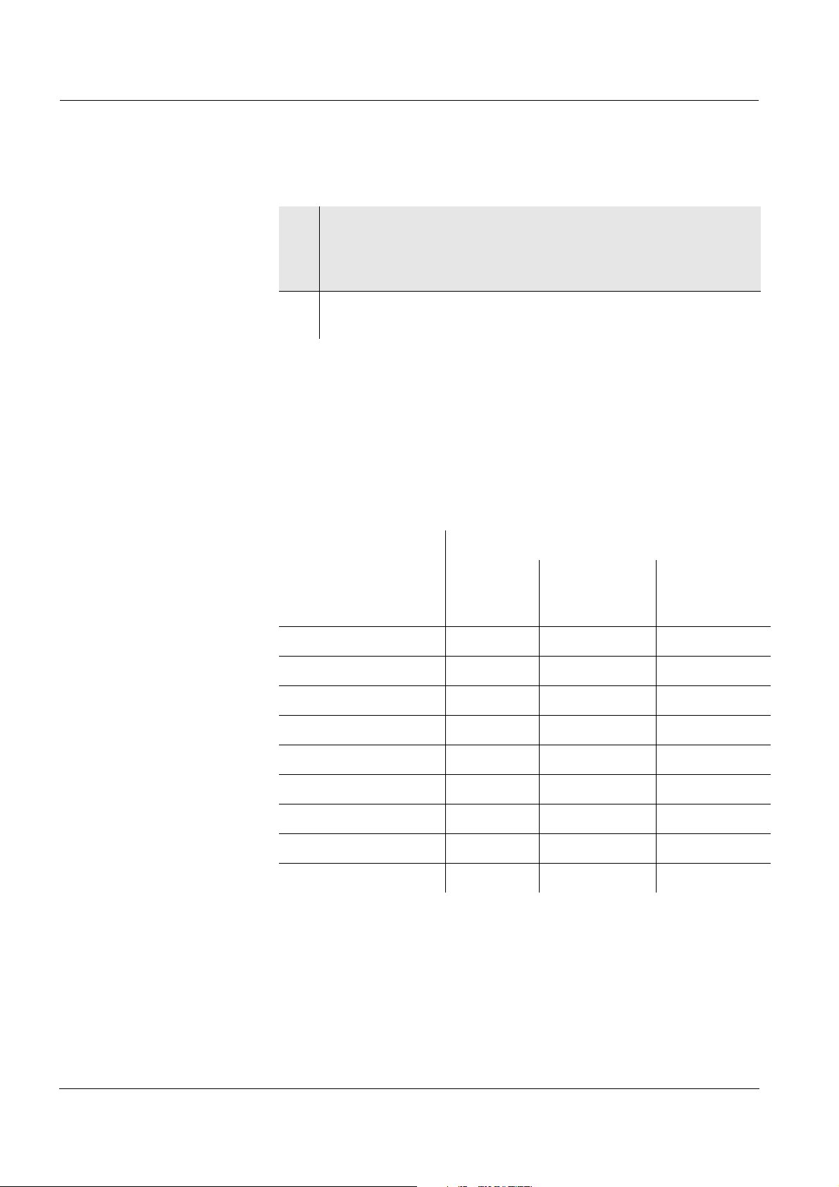
3.7 Connecting optional accessories
The ProLab 4000 has several interfaces to connect accessories to. To
connect a device, find the suitable interface in the following table.
More information on how to operate an interface is provided with the
description of the interface.
Interface
Accessory RS232
(see
page 29)
USB-B
(USB Device)
(see page 31)
USB-A
(USB Host)
(see page 32)
PC x x
Printer x x
Burette X
USB mouse x
USB memory x
USB card reader x
USB keyboard x
USB barcode reader x
USB hub x
28
ba75646e03 12/2012
ProLab 4000 Commissioning
3.7.1 RS232 interface (serial port)
PC, printer and burettes can be connected via the RS232 interface.
Data that is transmitted to the interface with <PRINT> can be printed
out with a printer or received with a terminal program if a PC is connected.
Note
If the burette control is active, data output to the RS232 interface
(printer) is deactivated.
On the meter, the following transmission data are permanently set for
the RS232 interface:
– Baud rate: 4800
– Data bits: 8
– Stop bits: 1
– Parity: none
The transmission data must agree with the transmission data for the
interface adjusted on the burette.
Check the transmission data adjusted on the burette, and change
them if necessary (see operating manual of your burette).
Operation with RS232 Connect the interface of the ProLab 4000 to the devices using the Z390
(PC) or Z893 (external USB printer Z890) cable.
Set up the following transmission data on the PC/printer:
Baud rate selectable between: 1200 ... 115200
The baud rate must agree with the baud rate set on
the PC/printer.
Handshake RTS/CTS
PC only:
Parity none
Data bits 8
Stop bits 1
ba75646e03 12/2012
Note
Pin assignment of the socket: See page 203.
29

Commissioning ProLab 4000
30
ba75646e03 12/2012

ProLab 4000 Commissioning
3.7.2 USB-B interface (USB Device)
You can connect a PC to the meter via the USB-B interface(USB
Device).
Data that is transmitted to the interface with <PRINT> can be printed
out with a printer or received with a terminal program if a PC is connected.
The USB driver of the enclosed CD-ROM must be installed for the interface to be available for the PC.
Installation of the USB
driver on the PC
Operation at USB-B
(USB Device)
System requirements of the PC for installation of the USB driver:
PC with Pentium processor or higher with at least one free USB con-
nection and CD-ROM drive
Windows 2000, XP.
1 Insert the supplied installation CD in the CD drive of your PC.
2 Connect the meter to the USB input of the PC via the USB
cable.
Windows automatically installs the driver for the meter. Follow
the Windows installation instructions as necessary.
The meter is listed as a virtual COM interface among the connections in the Windows instrument manager.
Connect the interface on the ProLab 4000 to the PC using a cable with
a USB-A and a USB-B plug.
Set up the following transmission data on the PC/printer:
Baud rate selectable between: 1200 ... 115200
The baud rate must agree with the baud rate set on
the PC/printer.
ba75646e03 12/2012
Handshake RTS/CTS
PC only:
Parity none
Data bits 8
Stop bits 1
31

Commissioning ProLab 4000
3.7.3 USB-A interface (USB Host)
You can connect the following devices to the USB-A interface (USB
Host) at the ProLab 4000:
Accessory Use
USB mouse Simple operation of the ProLab 4000 like a
PC
USB printer Simple output of data to the printer with the
<PRINT> key
USB memory Simple data backup on an external USB
medium
USB card reader Simple data backup on an external memory
card
USB keyboard Input of text with the keyboard
Operation at USB-A
(USB Host)
USB barcode reader Input of data such as sample designations
using a barcode.
Data input using the barcode reader is
always possible whenever it is possible to
input data via the keyboard.
USB hub (USB 2.0) Multiplication of the number of USB-A inter-
faces USB Hostfor simultaneous operation
of several USB devices
Connect the interface on the ProLab 4000 to the external device using
a cable with a USB-A and a USB-B plug.
The device is automatically recognized and is immediately operable.
32
ba75646e03 12/2012

ProLab 4000 Operating principles
4 Operating principles
This section contains basic information on the operation of the
ProLab 4000.
4.1 Operating and display elements
Mouse The ProLab 4000 is designed for mouse operation. With a mouse click
you can carry out all functions except for the entry of characters and
numerals. This means the ProLab 4000 can be operated as easily as a
software on the PC.
Keys Frequently required functions such as Store (<STO>), Calibrate
(<CAL>) or Print (<PRINT>) are directly available using keys. In this
operating manual, keys with dedicated functions are identified by the
key labeling, bold letters and angle brackets, e.g. <OK>.
Note
When the meter is operated with the mouse, all key functions are
available in a context menu (right mouse button).
Window The screen shows display windows and dialog boxes like a PC soft-
ware. Only one window is active at a time. The active window has a colored title bar. Windows that are not active have a grayed out title bar.
In the measured value display, for each channel there is a window with
special menus for the displayed measured parameter.
Windows contain further operating elements such as buttons, register
cards, selection lists, option fields and input fields.
When operating the meter without the mouse, use the [Tab] softkey to
activate the open window while scrolling, e.g. individual channels or the
main menu.
Buttons Functions in dialog boxes are executed using buttons. In this operating
manual, buttons are identified by angle brackets. Example: [Continue]
or [OK].
When operating without the mouse the buttons have to be selected
first. Then the respective function can be executed with <OK>. The
[Cancel] button can always be operated with the <ESC> key directly.
ba75646e03 12/2012
33

Operating principles ProLab 4000
1
2
3
6
12
5
Main menu
Sensor menu
Display Depending on the operating situation, the color display shows mea-
surement data, calibration steps, setting dialogs or stored data.
Main menu (1)
1 Main menu
2 Channel
3 Menu for a measured parameter
5 Info line
6 Softkey assignment
12 Softkeys
34
ba75646e03 12/2012

ProLab 4000 Operating principles
In the main menu, there are sensor independent functions and settings:
Manage configurations (File ) (see page 190)
Store current measurement data, and display and edit stored mea-
surement and calibration data (Memory) (see page 161)
System settings such as language, date, time, color assignment,
interface settings and general measurement settings (System) (see
page 56)
Select the measurement data to be displayed (Window)
Manage user data (User ) (see page 171)
ba75646e03 12/2012
35

Operating principles ProLab 4000
Channel (2) In the measured value display, for each connected sensor you can see
a channel with special menus for the displayed measured parameter
(Measuring, Calibration).
Menu for a measured
parameter (3)
Info line (4) The info line shows the date and time, information or instructions on the
Softkey assignment and
softkeys (5+6)
Menus for a measured parameter comprise sensor dependent functions and settings:
Calibration settings and calibration data (Calibration) (see section
C
ALIBRATION in the chapter for the respective sensor)
Temperature settings such as usage of the temperature sensor of
another sensor, manual temperature setting (Measuring)
The measured value display with recorder (see page 172)
Resetting the sensor settings
Special measurement settings (Measuring)
A detailed description of the functions is given with the description of
the measured parameter.
current situation.
Softkeys provide additional, situation-related functions. In this operating manual, softkeys are indicated by the currently displayed function,
bold letters and angle brackets, e.g. [Tab].
The current functions are displayed in the four fields in the lower display
(empty field = no function).
36
ba75646e03 12/2012

ProLab 4000 Operating principles
4.2 File system
Files With the ProLab 4000 you can store data in files just like using a PC.
Different data is stored in an extra file, such as
manually stored measured values
automatically stored measured values
recorder data
A complete overview of the data that can be stored and the corresponding file formats is given in chapter 11 M
File system The ProLab 4000 creates an individual directory with the user name for
each registered user.
In his/her directory, each user can:
Create folders
Store data
EMORY (see page 161).
Delete files
View stored files
File dialogs such as Save as always suggest the directory of the registered user.
Note
If an external USB memory is connected, the external memory
appears as a folder in the directory of the user.
Only the administrator can move to a higher directory and in other user
folders.
ba75646e03 12/2012
37

Operating principles ProLab 4000
7
PQRS
4.3 Entry of numerals, letters and characters
Numerals, letters, punctuation marks and special characters are
entered on the alphanumeric keypad on the meter or an external keyboard.
Entering characters is required in operating situations such as the following:
Entry of the date and time
Entry of an ID, e. g. if you want to store measurement data
Entry of the user name and password
User management
Character set The following characters are available:
Numerals 0 ... 9
Letters A ... Z
Punctuation marks . -
Operating principle Characters can be entered as long as an input field is displayed.
The keys of the alphanumeric are assigned to the characters that are
printed on them. Example: With the <PQRS 7> key you can enter the
following characters: 7, P, Q, R, S.
The required character is selected by pressing the key several times
(similar to a cell phone). The numeral appears on the first pressing if
the key is assigned to several characters. One keypressing is sufficient
to enter a numeral.
The key for punctuation marks (<- .>) is assigned to a decimal point of
minus sign, depending on the context. If a number is in front of the
punctuation mark, a decimal point is automatically displayed, in all
other cases a minus (-).
A character is taken over in the input field if
the character is highlighted longer than one second,
the character is confirmed with <OK>,
another alphanumeric key is pressed.
Operating example:
Entering an ID
The input field for an ID appears if you press the <STO> key to store
measurement data. A dialog with input fields for the ID and comment
opens up. In the following example, a measurement dataset with the ID
"Test" should be stored.
1 Press <TUV 8> several times until "T" appears in the input line.
After approx. 1 second the character is taken over.
38
ba75646e03 12/2012

ProLab 4000 Operating principles
2 Complete and confirm the ID with <A...9>.
Mouse operation:
With the mouse, you have in all entry fields the additional option of
showing a keyboard with the right mouse button. You can then enter
letters or numerals with the mouse.
Correcting wrong
entries
Move the cursor behind the character to be deleted with <><>.
Then delete the character in front of the cursor with <DEL>.
ba75646e03 12/2012
39

Operating principles ProLab 4000
4.4 Navigation
The dialog with the meter takes place through menus and dialog boxes
as usual with any PC software. In each dialog box there are operating
elements such as register cards, selection lists, buttons or input fields.
Note
The ProLab 4000 is designed to be operated with a mouse. A suitable
mouse is included in the scope of delivery.
General operating
principles
If you wish to operate the meter without using a mouse, find some general operating principles listed below.
Key / softkey
[Tab] Select main
[Menu] Open main
Measured
value display
menu or
channel
Menu Dialog box
- Select an element
such as a register
card or button
--
menu or
selected
channel
<><>
and
<><>
<OK> - Execute a menu
- Select a menu
item
item, e.g. start an
action or open a
Select a subelement in a dialog
box
Execute the function of the
selected button
dialog box.
<ESC> - Close the menu Cancel current
action without
change
40
ba75646e03 12/2012

ProLab 4000 Operating principles
Menu / chan-
nel, not high-
Channel,
highlighted
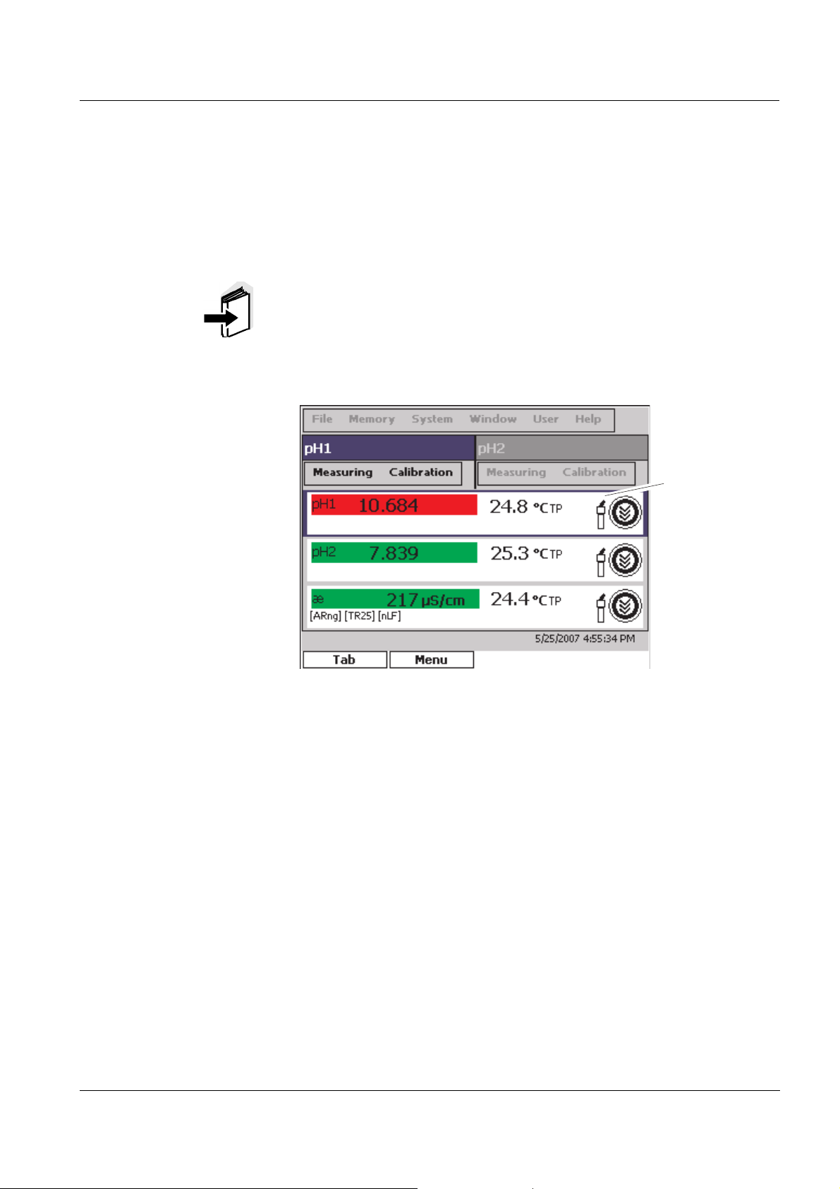
4.4.1 Navigation in the measured value display
The display shows, for example, the measurement data of all activated
channels, the main menu, the sensor menu and the softkey functions.
Using [Tab], activate channels or the main menu
Using [Menu], open the menu line.
Using <MODE>, change the measured parameter for the selected
channel (e. g. pH ><− mV).
Using the functions keys on the meter such as Calibrate (<CAL>),
Store (<STO>), Print (<PRINT>), Display stored measurement data
(<RCL>), Manual stability control (<SC>) etc. you can execute further functions.
Operating example:
Highlighting a channel
A channel is an indication on the display that corresponds to a physical
connection at the meter. The number of the channel is displayed with
the selected measured parameter, e.g. pH1, pH2.
1 In the measured value display, highlight the main menu or a
channel with [Tab].
The highlighting moves on with each keypressing.
ba75646e03 12/2012
Mouse operation:
1 Select a channel or menu name with a mouse click.
41

Operating principles ProLab 4000
4.4.2 Navigation in menus
A menu item contains submenus, executes a function or opens a dialog
box.
The selection is made with the <><> and <><> keys or the
mouse.
The current selection is highlighted.
Menus
Submenus are marked by an arrow to the right (). Menus are
opened with <OK>.
Functions
Functions are indicated by the name of the function. They are immediately carried out by confirming with <OK>.
Dialog boxes
Settings are marked by dots (...).
The relevant setting window is opened with <OK>.
Operating example:
Navigation in the menu
Menus are available for general settings and functions and for each
individual measured parameter.
1 In the measured value display, highlight the main menu or a
channel with [Tab].
A highlighted channel is marked by a frame.
2 Open the menu with the current selection with [Menu].
3 Highlight a menu item with <><> and <><>.
The highlighted menu item is displayed inverse.
4 Confirm the highlighted menu item with <OK>.
42
ba75646e03 12/2012

ProLab 4000 Operating principles
5 Highlight a menu item with <><> and <><>.
The highlighted menu item is displayed inverse.
6 Confirm the highlighted menu item with <OK>.
When a function is executed the main menu is closed and the
function executed, or a dialog box opens up.
Mouse operation:
1 Select a menu name with a mouse click.
The menu pops up.
2 Select a menu item and confirm with a mouse click.
When a function is executed the main menu is closed and the
function executed, or a dialog box opens up.
ba75646e03 12/2012
43

Operating principles ProLab 4000
4.4.3 Navigation in dialog boxes
Dialog boxes contain further subelements such as register cards,
selection lists and buttons. The elements are selected with the [Tab]
softkey. Within a list or register card, they are selected with the
<><> or <><> keys.
Operating example:
Navigation and settings
in dialog boxes
1 Using [Tab], highlight individual elements in a dialog box.
Highlighted elements such as register cards, option fields or
buttons are marked by a dotted frame.
Highlighted lists are displayed inverse.
2 If an element such as a register card or list that allows a further
selection is highlighted:
Highlight a different selection in element with <><> or
<><>.
3 If an element such as a button that executes a function is high-
lighted:
Use <OK> to execute the function.
Mouse operation:
1 Select an element with a mouse click.
The relevant function is executed.
44
ba75646e03 12/2012

ProLab 4000 Operating principles
4.4.4 Navigation in the file selection dialog box
The file selection dialog is opened if a file is to be created, stored,
selected or deleted.
All files are stored in the folder of the user. Each user can create or
delete subfolders in his/her folder.
The file dialog box contains further subelements such as
symbol buttons,
a list with files and subfolders,
an input field for the file name and
buttons.
The elements are selected with the [Tab] softkey. Within a list or register card, they are selected with the <><> or <><> keys.
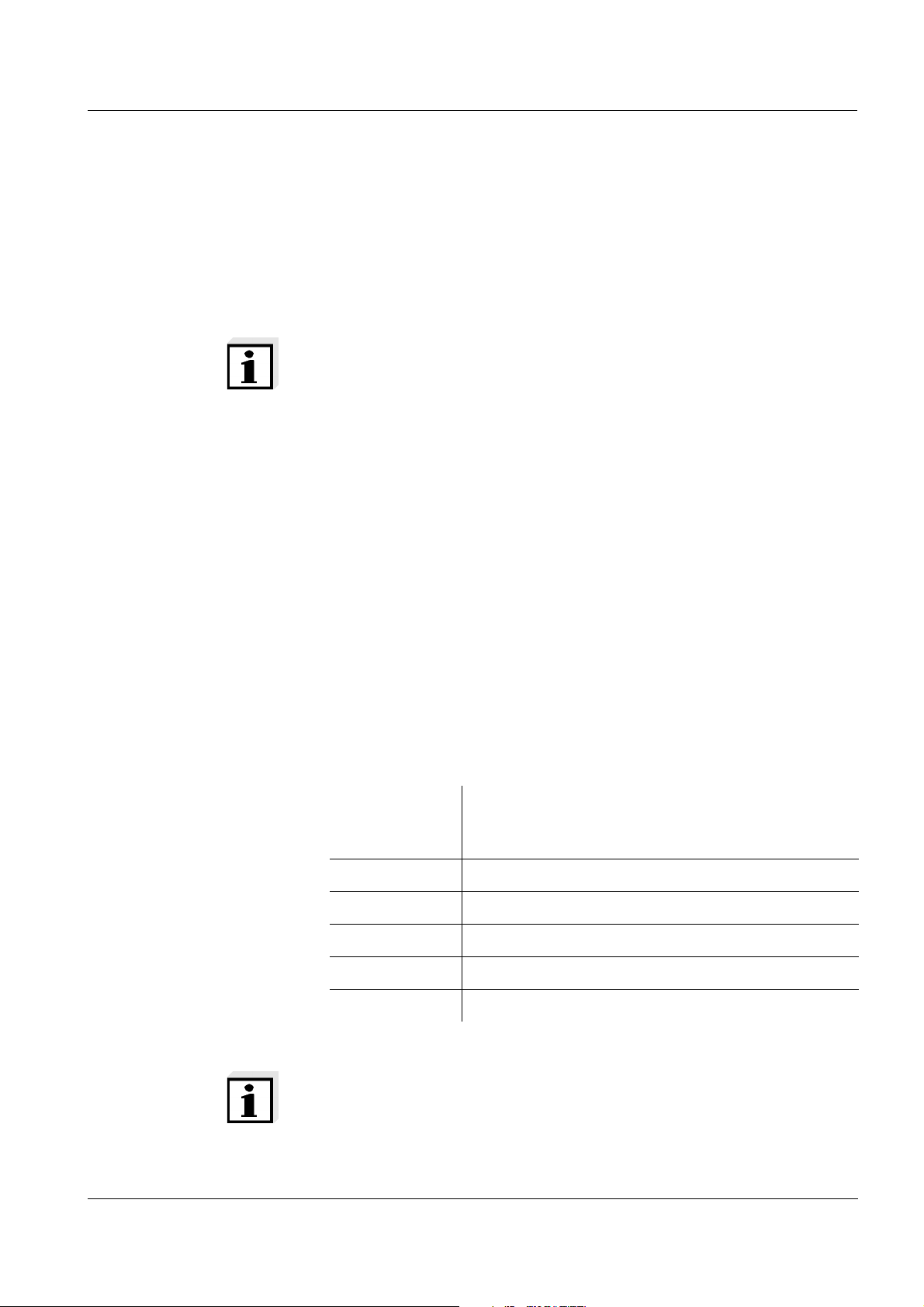
The functions of the symbol buttons available with the keypad using the
[Menu] softkey. A context menu opens up that contains all key functions.
ba75646e03 12/2012
Note
Functions in file dialog boxes that are activated with symbol buttons
can be activated via the contest menu with [Menu] if you operate without the mouse. Examples:
: move one folder up
: create new folder
: display/hide header
45

Operating principles ProLab 4000
Operating example:
Navigation and settings
in file selection dialogs
1 Highlight an element in a file dialog box with [Tab]. Highlighted
elements such as buttons are marked by a dotted frame.
Highlighted input fields are displayed inverse.
2 If an element such as the file list in the current folder allows a
further selection:
Highlight a different selection in element with <><> or
<><>.
3 If an element such as the input field for the file name allows an
entry:
Enter a name with <A...9>.
4 If an element such as a button that executes a function is high-
lighted:
Use <OK> to execute the function.
Mouse operation:
1 Select an element with a mouse click.
The assigned function is executed.
2 If an element such as the input field for the file name allows an
entry:
Enter a name with <A...9>.
46
ba75646e03 12/2012

ProLab 4000 Access to the meter
5 Access to the meter
5.1 Switch the meter on and off
Switching on
Switching off
Login with password
1 Switch the meter on with <On/Off>.
The self-test, meter designation, software version and subsequently the Login dialog box appear.
1 Switch off the meter with <On/Off>.
5.2 Login as a user
After switching on, the Login dialog box pops up. Depending on the
adjusted type of access control, the dialog box contains:
a list to select a user name and a field to enter a password or
the prompt, Place the electronic key on the reader field.
In the delivery condition, access is possible with password.
ba75646e03 12/2012
1 Select an item in the User name list.
2 Enter the correct password for the user name and confirm with
<OK>.
The login has taken place.
47

Access to the meter ProLab 4000
Note
The default password for the administrator is "00001".
For your safety, change it as soon as possible (see page 49). No
password entry is required for anonymous access.
Login with electronic
key
Login with electronic
key and password
The Login dialog box displays the instruction:
Place the electronic key on the reader field.
1 Place the electronic key on the read field and leave it there for
approx. 2 seconds until the key has been recognized.
The user name and key number is displayed. The login has
taken place.
The Login dialog box displays the instruction:
Place the electronic key on the reader field.
1 Place the electronic key on the read field and leave it there for
approx. 2 seconds until the key has been recognized.
The user name and key number is displayed.
2 Enter the correct password and confirm with <OK>.
The login has taken place.
Note
Depending on user rights, individual functions and settings may be
grayed out and thus locked.
More information on user rights: See page 51.
48
ba75646e03 12/2012

ProLab 4000 Access to the meter
5.3 Password for login
If the used of a password for login to the meter was set by the administrator, each user has to enter his or her password during the login.
The ProLab 4000 is delivered with the password "00001" for the user
name, Administrator . Change this password as soon as possible.
5.3.1 Changing the password
All users can change their own password.
A valid password consists of at least 5 characters.
1 Open the User / Change password... menu.
The Change password window opens.
The old password is in the Old password field.
2 Enter the new password in the New password field.
3 Enter the new password once again in the Confirm password
field.
4 Confirm the new password with [OK].
The password is changed.
The Change password window is closed.
5.3.2 Assigning a password
During the first login with the new user name the Change password
window appears. Here the password is set by the user. A valid password consists of at least 5 characters.
5.3.3 Forgotten the password?
If the access control requires the entry of a password, access to the
meter is not possible without the password.
Users The administrator can delete the password for user profiles (see
page 53).
ba75646e03 12/2012
49

Access to the meter ProLab 4000
5.4 Lock
During operation (e.g. if the automatic storing function is active), the
activated lock prevents the inadvertent use of the meter with the name
of the registered user.
The lock can only can only be released with the currently registered
electronic key or the administrator key.
Note
The lock can only be activated in the measuring mode of operation.
With anonymous access, the Activate lock function is not available.
Activating the lock
Releasing the lock
1 Activate the lock in the System / Activate lock menu.
The meter is locked against inadvertent use.
1 Press any key.
The login window pops up.
2 Log in with the password, electronic key or electronic key and
password.
The lock is released.
50
ba75646e03 12/2012

ProLab 4000 Access to the meter
5.5 Access control and user rights
You as the administrator define the type of access (assess control) to
the ProLab 4000. In addition, you define the rights to carry out functions
and measurements for the users (user rights).
When the meter is delivered, only the enclosed electronic administrator
key has an access authorization for the meter.
The administrator can set up access authorizations for electronic user
keys (see below).
Anonymous access without password and electronic key (user name,
Anonymous) is always possible. Measurement and calibration data is
identified by the user name, Anonymous.
After the login as administrator, the user management functions are
available in the Access control and Administration register cards of the
User / Administration... menu.
Access control In the Access control register card you define the general access set-
tings that will apply to all users.
User rights Each user is given user rights with the ProLab 4000. The user rights are
limited by the user type and configuration:
User type User rights
Administrator Calibrate and measure
Create file for manual storage
Create user configuration
Define type of access to the meter
User administration
Delete all files
Users
without configuration
Calibrate and measure
Create file for manual storage
Create user configuration
Delete files in their own folder
with configuration Calibrate and measure
(limited by settings in configuration file)
ba75646e03 12/2012
51

Access to the meter ProLab 4000
User type User rights
Anonymous Calibrate and measure
Create file for manual storage
Create user configuration
Delete files in the folder, Anonymous
Note
Only one user can be the administrator. The administrator is adjusted
in the delivery condition. The administrator can only create users of
the type, user.
5.5.1 Access control
The administrator defines the type of access to the meter.
The setting applies to all users and the administrator.
Type of access Description
Access with password The meter can only be unlocked by enter-
ing the password for a certain user.
Access with electronic
key
Access with el. key and
password
Access with electronic key only. No additional password is required here.
To be able to work with the meter, a password has to be entered in addition to
access with the electronic key.
1 Open the User menu with Administration....
The User administration dialog box pops up.
The General register card is open.
2 Select the type of access and confirm with [OK].
The new setting is active when the ProLab 4000 is switched on
the next time.
52
ba75646e03 12/2012
ProLab 4000 Access to the meter
5.5.2 User management and assigning user rights
The ProLab 4000 has basic user management functions. The administrator can
add new users
delete users
delete the password assigned to a user
store a configuration file for users.
The configuration file contains measurement settings that cannot be
changed by the user. Besides, the administrator considerably
restricts the rights of the user.
The user cannot
– change or reset any defined measurement settings
– delete any files
– create or change any configuration
– backup any data
hide the anonymous access or any user. If a user or anonymous
access is hidden, it is no longer available in the login dialog and cannot be selected.
The administrator also defines the user rights for any new user (see
page 51).
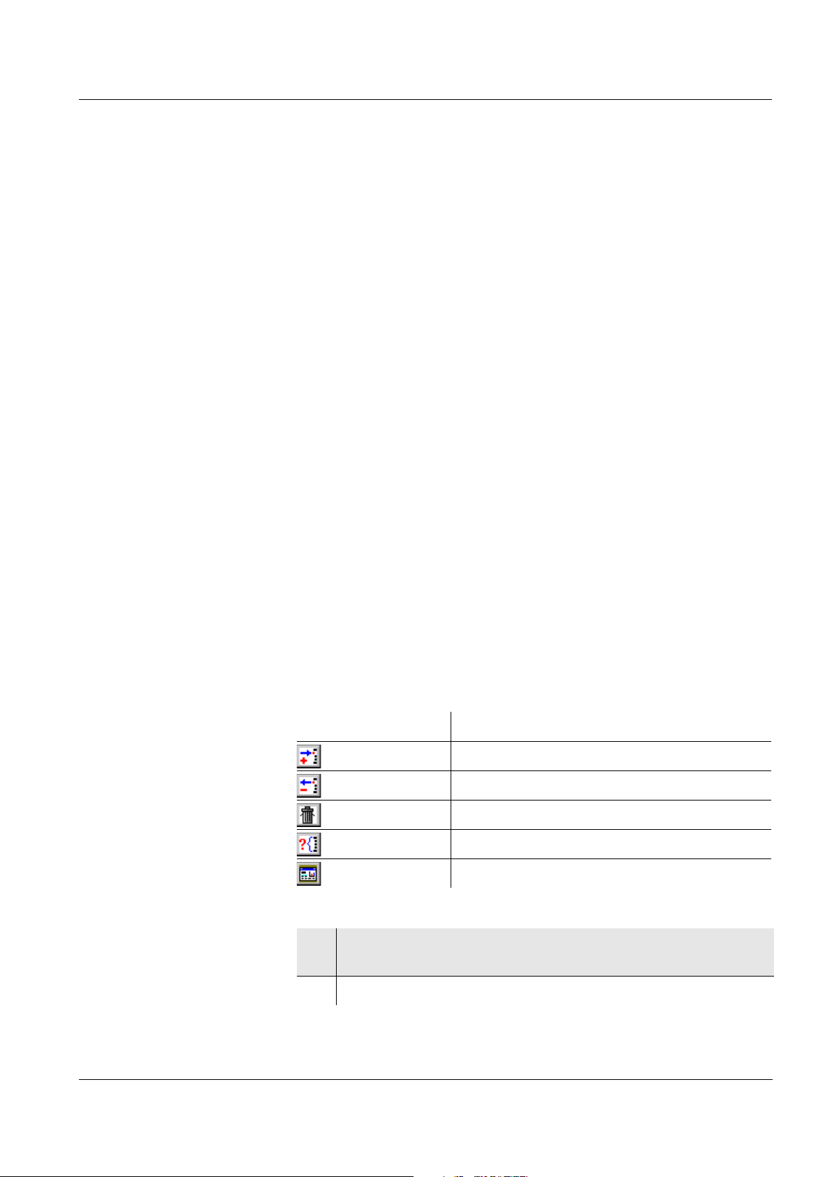
The symbol buttons are used for user management with the mouse.
The relevant functions are available as a context menu with the [Menu]
softkey when operating with the meter keypad.
Symbol button Function (designation in context menu)
Add user
Delete user
Delete old password
Hide user/visible
Add configuration...
ba75646e03 12/2012
1 Open the User menu with Administration....
The User administration dialog box pops up.
2 Open the Administration register card.
53

Access to the meter ProLab 4000
Adding a new user
Assigning a
configuration to a user
1 Enter a new user name in the New user field.
or
Place an electronic user key on the reader field.
The key number and a user name already stored in the key are
displayed.
If necessary, enter a new user name in the New user field.
2 In the context menu, select the menu item, Add user.
The new user is included in the list of registered users.
On access with the electronic key, the user name is at the
same time stored in the electronic key.
3 Remove the electronic key from the reader field.
4 Highlight a user in the list of users.
5 In the context menu, select the menu item, Add configuration....
The Open file dialog box pops up.
6 Select a configuration file and confirm with [OK].
The configuration file is permanently assigned to the user and
is also displayed in the list of users.
Erasing a registered
54
user
7 Highlight a user in the list of users.
8 In the context menu, select the menu item, Delete user.
A safety query appears. After confirming the safety query the
access authorization for the currently highlighted user is
deleted.
ba75646e03 12/2012

ProLab 4000 Access to the meter
Erasing the password
for a registered user
Hiding / displaying a
user
Exiting the user
management
9 Highlight a user in the list of users.
10 In the context menu, select the menu item, Delete old pass-
word.
A safety query appears. After confirming the safety query the
password for the currently highlighted user is deleted.
11 Highlight a user in the list of users.
12 In the context menu, select the menu item, Hide user/visible.
If the user is hidden, the [Hidden] labeling is displayed in the list
of users.
13 Confirm the settings with [OK].
The user settings are active.
5.6 Lost your electronic key?
Without an electronic key with access authorization, anonymous
access is possible only.
Electronic user key Keys for additional users can be obtained from SI Analytics GmbH.
The access authorization for new keys is set up by the administrator
(see page 53).
Electronic administrator
key
If the electronic administrator key is lost, the access authorization for a
new electronic administrator key can be set up in the factory only.
The addresses and telephone numbers of SI Analytics GmbH are given
on the cover of this operating manual.
ba75646e03 12/2012
55

System functions ProLab 4000
6 System functions
System functions are all functions that are independent of the probe.
6.1 Overview: System settings
The following sensor-independent meter features can be adjusted in
the System menu and its submenus:
Menu item Setting Description
System
– Data output...
– USB printer ()
– USB interface /Baud () / 1200 ... 115200 Baud rate of the data interface
– Serial interface /Baud () / 1200 ... 115200 Baud rate of the data interface
– Output format – ASCII
– CSV
– Autom. printout... Printout interval Automatic output of the measure-
– Reset - Resets the system settings to the
– Measuring
– Autom. stability control () You can activate or switch off the
Output format for data transmission
For details, see page 187
ment data to the interfaces at the
specified interval.
default values.
For details, see page 66
automatic stability control function (see page 63).
56
– Temperature unit – Celsius
– Fahrenheit
– Connect Ref1/Ref2 () Use reference electrode of the
All temperatures are displayed
with the selected unit.
other pH/ISE input
ba75646e03 12/2012

ProLab 4000 System functions
Menu item Setting Description
System
– Signal On () Switches on or off the acoustic
signal. The signal sounds e.g.
when a stable measured value
has been recognized (stability
control)
– Country and language...
– Country List with over 100
countries
With this setting you can select
the country-specific notation for
the date, time and numbers.
The setting applies to all data
that is stored or output to an
interface.
– Language – Deutsch
Select the menu language
– English
– Francais
– Espagñol
– Date and time...
– Date Setting the date
– Time Setting the time
– Color code... – SC stable
– SC not stable
– Instruction display
– Information dis-
play
Settings in the Color code group
field change the background
color for display indications with
certain states (stability criterion
for stable measured values met /
not met) and for indications in the
info line.
– Activate lock () After a user login with the elec-
ba75646e03 12/2012
tronic key, the key lock can be
activated here. The meter is
locked against operational
actions until the electronic key is
applied again.
57

System functions ProLab 4000
6.2 Selecting the language
Menus can be displayed in different languages. The language is
selected in the System main menu.
1 Open the System / Country and language... menu.
The Country and language window opens.
2 Select a language in the Language list.
The active language is highlighted.
3 Confirm the selection with [OK] .
The language is changed.
6.3 Selecting the country
With this setting you can select the country-specific notation for the
date, time and numbers. This data is stored and output to an interface
in the country-specific notation.
1 Open the System / Country and language... menu.
The Country and language window opens.
2 Select a country in the Country list.
The active country is highlighted.
3 Confirm the selection with [OK] .
The country is changed.
58
ba75646e03 12/2012

ProLab 4000 System functions
6.4 Setting the date and time
The data and time are displayed in the local format, according to the
Country setting (see above). The date and time are set in the menu,
System / Date and time....
1 Open the System / Date and time... menu.
The Date and time window opens.
2 Select the time zone in the Time zone field.
3 If necessary, mark the Automatic daylight saving time field.
4 Select the date.
5 Enter the time.
6 Confirm the entries with [OK] .
The date and time are taken over.
ba75646e03 12/2012
59

System functions ProLab 4000
6.5 Selecting the channels for measured value display
In the Window / Channels... you can define which channels are visible
in the measured value display.
Depending on the number of activated measurement data one, two or
three sensor data are displayed at the same time.
Menu item Description
pH/U/ISE Probe 1 Display or hide the sensor data of the pH/U/ISE
1 channel.
pH/U/ISE Probe 2 Display or hide the sensor data of the pH/U/ISE
2 channel.
Cond Probe Display or hide the Cond sensor window.
6.6 Interfaces for data download
The meter has three interfaces to which data can be downloaded:
RS232: serial printer or PC
USB-B (USB Device): PC
USB-A (USB Host): USB printer
You can specify to which interfaces data will be downloaded at the
same time.
1 Open the System / Data output... menu.
The Data output window opens.
60
ba75646e03 12/2012

ProLab 4000 System functions
2 Mark the option fields, USB printer, Serial interface and USB
interface.
The interfaces are selected for data download.
3 If data should be downloaded to the Serial interface or USB
interface interfaces:
Set the baud rate in the respective Baud list field.
The interface is ready for data download.
6.7 Temperature
The temperature affects the measurement results. You can select the
unit of the temperature display. The temperature is determined automatically with an external temperature sensor or one that is integrated
in the sensor. It is also possible to enter temperature values manually.
6.7.1 Temperature unit
Measured temperature values can be displayed in the unit, °C (degrees
Celsius) or °F (degrees Fahrenheit).
1 Open the System / Measuring / Temperature unit menu and
select the unit, Celsius or Fahrenheit.
The selected temperature unit is active.
ba75646e03 12/2012
61

System functions ProLab 4000
6.7.2 Temperature measurement
For reproducible measurements it is essential to determine the corresponding temperature value.
The measuring system receives the temperature value from:
a temperature sensor integrated in the sensor,
a temperature sensor integrated in another sensor,
an external temperature sensor NTC30 or Pt1000, or
manual input of the temperature value.
On the display, the used temperature sensor is labeled with TP,
pH1 TP, pH2 TP or Cond TP
.
Using an integrated
temperature sensor
Using the temperature
sensor of another
sensor
Sensors with an integrated temperature sensor always measure the
measured parameter and temperature simultaneously. If the integrated
temperature sensor is recognized, the measured temperature value
and the TP status indicator appear on the display.
If no temperature sensor is available for a pH/ISE channel, you can
measure the temperature with the integrated temperature sensor of
another sensor.
To do so proceed as follows:
1 Immerse two electrodes in the measuring sample.
2 Highlight a channel in the measured value display.
3 In the sensor menu, select the Alternative TP menu item, e.g.
Measuring / Alternative TP.
The temperature measurement is active.
For checking purposes, the used temperature sensor is
indicated on the display.
Using an external
temperature sensor
62
If you want to measure the temperature using an external temperature
probe, proceed as follows:
1 Connect a temperature sensor to the measuring module.
2 Immerse the temperature sensor in the test sample.
The measured temperature value is shown on the display.
ba75646e03 12/2012

ProLab 4000 System functions
SC stable
SC not stable
6.8 Automatic stability control
The Autom. stability control function continuously checks the stability of
the measurement signal. The stability has a considerable impact on the
reproducibility of measured values.
You can activate or switch off the Autom. stability control function
(menu, Autom. stability controlSystem).
The Autom. stability control function is carried out:
as soon as the measured value is outside the allowed stability range
when you switch over between the measured parameters with
<MODE>.
The stability of the measured value is indicated by the background
color of the measured value. In the delivery condition, the SC stable /
SC not stable conditions are assigned to the following colors:
Color Meaning
red SC not stable
Stability criteria not met
green SC stable
Stability criteria met
ba75646e03 12/2012
63

System functions ProLab 4000
Note
The stability criteria that apply to a measured parameter are given in
the description of the measured parameter.
You can change the assignment of colors to conditions (see page 64).
6.9 Color assignment
For easy differentiation, the following conditions are highlighted by a
background color:
Stability criterion met / not met
Indications in the info line: Instruction / info display
You can adapt the colors yourself for these conditions.
1 Open the System / Color code... menu.
The Color code window pops up.
2 Open the Color palette window with [...].
3 Select a color.
4 Confirm the color with [OK].
The color is entered for the selected condition.
64
5 If necessary, change the background color for other conditions.
6 Confirm the color assignment with [OK].
The new color assignment is accepted and immediately
effective.
ba75646e03 12/2012

ProLab 4000 System functions
6.10 Reset
You can reset (initialize) all sensor settings and sensor-independent
settings separately from each other.
6.10.1 Resetting the sensor settings
Note
The calibration data is reset to the default settings together with the
measuring parameters. Recalibrate after performing a reset.
The sensor settings are reset in the sensor menu.
In the measured value display, activate the relevant sensor window
[Tab] and open the menu with [Menu].
pH The following settings for pH measurements are reset to the default
settings with the Reset pHMeasuring function:
Setting Default settings
Calibration interval... 7 d
Slope in mV/pH
Measured parameter pH
pH resolution High
Zero point 0 mV
Slope -59.16 mV/pH
Temperature, manual 25 °C
Cond The following settings for conductivity measurements are reset to the
default settings with the Reset CondCond-Setup function:
Setting Default settings
Calibration interval... 150 d
Measured parameter
ϰ
Cell constant 0.475 cm-1 (Calibrated cell constant)
0.475 cm
-1
(Adjustable cell constant...)
ba75646e03 12/2012
Temperature coeffi-
TC nLF
cient
Tref Tref 25
65

System functions ProLab 4000
Setting Default settings
Temperature coeffi-
2.000 %/K
cient (TC) of the linear
temperature compensation
TDS factor 1,00
6.10.2 Resetting the system settings
The following system settings are reset to the default settings with the
System / Reset function:
Setting Default settings
Language English
Temperature unit Celsius
Signal On
✓
Baud rate (Baud) 4800
Output format ASCII
66
ba75646e03 12/2012

ProLab 4000 System functions
6.11 List of open windows
The Window menu item in the main menu provides an overview of the
open windows of the ProLab 4000. Open recorder windows and the
measured value display of the indicated sensors appear in the list of
open windows.
1 Open the Window menu.
2 Select a window from the list.
The window is activated and displayed in the foreground.
Note
Recorder windows that are open and displaced can be maximized and
restored with the Maximize recorder function.
Recorder window
1 Open the Window / Maximize recorder menu.
Recorder windows that are open and displaced are maximized.
The first recorder window is displayed.
ba75646e03 12/2012
67

System functions ProLab 4000
68
ba75646e03 12/2012

ProLab 4000 pH
7pH
7.1 General information
Temperature
measurement
For reproducible pH measurements, it is essential to measure the temperature of the test sample.
You have the following options to measure the temperature:
Automatic temperature measurement with
– Temperature sensor (NTC30 or Pt1000) integrated in electrode
(if available).
– the integrated temperature sensor of another electrode that is
connected and immersed in the sample at the same time.
– an external temperature sensor (NTC30 or Pt1000).
Manual determination and input of the temperature.
The display of the temperature indicates the active temperature measuring mode:
Temperature
sensor
yes 0.1 °C Automatic with temperature
Resolution of
the temp. display
Mode
sensor
- 1 °C Manual
ba75646e03 12/2012
69

pH ProLab 4000
7.2 Measuring the pH value
7.2.1 Preparatory activities
Perform the following preparatory activities when you want to measure:
1 Adjust the temperature of the solutions and measure the cur-
rent temperature if the measurement is made without a temperature sensor.
2 Connect a pH electrode to the meter.
3 Highlight the channel of the pH electrode in the measured
value display.
4 If necessary, select the pH display with <MODE>.
5 With manual temperature input:
– Call up the input window for the manual temperature input
with Measuring / Setting of man. temp....
– Measure the temperature of the test sample using a ther-
mometer.
– Enter the measured temperature value and confirm it with
[OK].
6 Calibrate the meter with the electrode.
Note
An incorrect calibration of pH electrodes leads to incorrect measured
values. Calibrate regularly. The meter has to be calibrated before
measuring.
Temperature sensor You can measure with or without a temperature sensor. The TP display
indicator appears when a temperature sensor is connected.
Note
If using a pH electrode without temperature sensor, you can also use
the temperature sensor of another connected electrode or conductivity measuring cell (see page 62). In this case, the indication from
which channel the temperature value is taken appears next to the temperature value.
70
ba75646e03 12/2012

ProLab 4000 pH
7.2.2 Measuring
1 Perform the preparatory activities (see page 69).
2 Immerse the pH electrode in the test sample.
3 If necessary, select the pH parameter with <MODE>.
Stability control The Stability control function checks the stability of the measurement
signal. The stability has a considerable impact on the reproducibility of
measured values. The background color is red until the measured
value is stable. When the measured value is stable, the background
color switches to green.
Regardless of the setting for Autom. stability control (see page 63) in
the System menu, you can start the Stability control function manually
at any time.
1 Highlight the channel of the electrode in the measured value
display.
2 If necessary, switch to the pH parameter with <MODE>.
3 Freeze the measured value with <SC>.
In the status line, [SC] is displayed.
4With <OK> activate the Stability control function.
As long as the measured value does not meet the stability criterion, the background color is red.
As soon as the measured value is stable, the background color
is green. The current measurement data is downloaded to the
interface. The measured values of all channels meeting the criterion for stability control are marked by SC.
ba75646e03 12/2012
71

pH ProLab 4000
Note
You can terminate prematurely the Stability control function with
<OK> manually at any time. If the Stability control function is termi-
nated prematurely, the current measurement data is not downloaded
to the interface.
5 Using <SC> or <MODE>, release the frozen measured value.
The [SC] status display disappears.
Criteria With identical measurement conditions, the following applies:
Measured param-
Reproducibility Response time
eter
pH value Better than 0.01 > 15 seconds
72
ba75646e03 12/2012

ProLab 4000 pH
7.2.3 Measurement settings
All settings for pH measurements are in the Measuring menu.
Menu item Setting Description
Measuring
– pH resolution High ()
Medium
Low
Resolution of the pH display:
High = 0.001
Medium = 0.01
Low = 0.1
– Alternative TP () () = alternative temperature
sensor is used
( ) = no alternative temperature sensor is used
– Setting of man. temp... -35 ... +150 °C Entry of the manually deter-
mined temperature. For measurements without
temperature sensor only.
– Reset pH Resets all sensor settings to
the delivery condition (see
page 65).
– Recorder... Start recorder (see page 171).
ba75646e03 12/2012
73

pH ProLab 4000
7.3 Calibration
Why calibrate? pH electrodes age. This changes the zero point (asymmetry) and slope
of the pH electrode. As a result, an inexact measured value is displayed. Calibration determines the current values of the zero point and
slope of the electrode and stores them.
Thus, you should calibrate at regular intervals.
When do you have to
calibrate?
Buffer sets for
calibration
After connecting a non-ID electrode
After the CalClock has expired
You can use the buffer sets quoted in the table for an automatic calibration. The pH values are valid for the specified temperature values. The
temperature dependence of the pH values is taken into account during
the calibration.
No. Buffer set * pH values at
1 DIN
DIN buffers according to DIN 19266
and NIST Traceable Buffers
1,679
4,006
6,865
25 °C
9,180
12,454
2 TEC 2,000
25 °C
4,010
7,000
10,011
3 Merck1 * (Technical buffers) 4,000
20°C
7,000
9,000
74
4 Merck2 * 1,000
6,000
8,000
13,000
5 Merck3 * 4,660
6,880
9,220
6 Merck4 * 2,000
4,000
7,000
10,000
7 Merck5 * 4,010
7,000
10,000
ba75646e03 12/2012
20°C
20°C
20°C
25 °C

ProLab 4000 pH
No. Buffer set * pH values at
8 DIN 19267 * 1,090
4,650
6,790
9,230
9 Mettler EU 1,679
4,003
7,002
10,013
10 Mettler US * 1,995
4,005
7,002
9,208
11 Fisher * 2,007
4,002
7,004
10,002
12 Fluka * 4,006
6,984
8,957
13 Radiometer * 1,678
4,005
7,000
9,180
25 °C
25 °C
25 °C
25 °C
25 °C
25 °C
14 Baker * 4,006
6,991
10,008
15 Metrohm * 3,996
7,003
8,999
16 Beckmann * 4,005
7,005
10,013
17 Hamilton DC * 4,005
7,002
10,013
18 Precisa (Hamilton Duracal) * 3,996
7,003
8,999
25 °C
25 °C
25 °C
25 °C
25 °C
ba75646e03 12/2012
75

pH ProLab 4000
No. Buffer set * pH values at
19 Reagecon TEC * 2,000
25 °C
4,010
7,000
10,000
20 Reagecon 20 * 2,000
20°C
4,000
7,000
10,000
13,000
21 Reagecon 25 * 2,000
25 °C
4,000
7,000
10,000
13,000
22 Riedel-de Haen * 2,000
20°C
4,000
7,000
10,000
* Brand names or trade names are trademarks of their respective owners
protected by law (see page 215).
Note
The buffers are selected in the Calibration sensor menu (see
page 73).
Calibration points Calibration can be performed using one to five buffer solutions in any
order (single-point to five-point calibration). The measuring instrument
determines the following values and calculates the calibration line as
follows:
Displayed calibration data
1-point Zero point
Slope = Nernst slope (-59.16 mV/pH at 25 °C)
2-point Zero point
Slope
3-point to
5-point
Zero point
Slope
The calibration line is calculated by linear regression.
76
ba75646e03 12/2012

ProLab 4000 pH
Print date26.04.07 16 was selected:13
ProLab 4000 (06249876)
Current user: 1234567890
CALIBRATION pH
Calibration date20.04.07 10:14:03
A 161 1M-BNC-ID (A062498765)
User: Administrator
Calibration interval 7 days
AutoCal DIN 2-point TAuto SC
Buffer 1 6.86
Buffer 2 9.18
Voltage 1 7.2 mV 26.3 °C
Voltage 2 -171 mV 26.3 °C
Slope -59.2 mV/pH
Zero point -0.5 mV
Sensor +++
Note
You can display the slope in the unit, mV/pH or % (see page 73).
Stability control The calibration procedure automatically activates the stability control
function. The current measurement with stability control can be terminated at any time (accepting the current value).
Calibration record When finishing a calibration, the new calibration values are first dis-
played as an informative message. Then you can decide whether you
want to take over these values of the new calibration or whether you
want to continue measuring with the old calibration data. After accepting the new calibration values the calibration record is displayed.
Display of calibration
data and download to
interface
You can display the data of the last calibration (see page 166). Subsequently, you can transmit the displayed calibration data to the interface,
e. g. to a printer or PC, with the <PRINT> key.
Note
The calibration record is automatically transmitted to the interface
after calibrating.
Sample record:
ba75646e03 12/2012
77

pH ProLab 4000
Calibration evaluation After calibrating, the meter automatically evaluates the calibration. The
zero point and slope are evaluated separately. The worse evaluation of
both is taken into account. The evaluation appears on the display and
in the calibration record.
Display Calibration
record
+++ -18 ... +18 -60.5 ... -57.5
++ -22 ... +22 -57.5 ... -56
+ -26 ... +26 -61 ... -60.5
- -30 ... +30 -62 ... -61
Clean the electrode according to the
sensor operating manual
Error Error
Eliminate the error according to chapter
16 W
HAT TO DO IF... (page 197)
Zero point
[mV]
< -30 or
> 30
Slope
[mV/pH]
or
-56 ... -55
or
-55 ... -50
... -62 or
... -50
Preparatory activities Perform the following preparatory activities when you want to calibrate:
1 Connect a pH electrode to the meter.
2 Highlight the channel of the electrode in the measured value
display.
3 If necessary, select the pH display with <MODE>.
4 Keep the buffer solutions ready. Adjust the temperature of the
buffer solutions, or measure the current temperature, if you
measure without a temperature sensor.
78
ba75646e03 12/2012

ProLab 4000 pH
7.3.1 Carrying out a calibration procedure (example: AutoCal DIN)
Make sure the Calibration / pH calibration type / Buffer sets setting is
selected correctly and the AutoCal calibration type is marked (see
page 73).
Use any one to five buffer solutions of the selected buffer set.
The DIN calibration is described below. With other buffer sets, other
nominal buffer values are displayed. Apart from that, the procedure is
identical.
1 Perform the preparatory activities (see page 78).
2 Start the calibration with <CAL>.
The pHX calibration window opens.
ba75646e03 12/2012
3 If necessary, check whether the displayed buffer set agrees
with the used buffer set.
4 When measuring without temperature sensor:
Measure the temperature of the standard solution using a
thermometer.
Open the setting window for the temperature value with
[Man. temp.].
Enter the temperature and confirm with [OK].
5 Thoroughly rinse the electrode with distilled water.
6 Immerse the electrode in buffer solution 1.
7 Start the measurement with [Continue].
The measured value is checked for stability (Stability control).
79

pH ProLab 4000
1
2
3
4
1 Recognized nominal buffer value (referring to 25 °C)
2 Current electrode voltage
3 Current temperature value
4 Selected buffer set
8 Wait for the measurement with stability control to end.
or
Terminate the stability control with [OK].
The pHX calibration window for the according to buffer solution
pops up and the Finish with 1-point calibration infotext is dis-
played.
80
ba75646e03 12/2012

ProLab 4000 pH
9 Using [OK], confirm the Finish with 1-point calibration infotext
and take over the new calibration values.
The calibration record is displayed and output to the interface.
The calibration procedure is finished.
or
Continue the calibration with [Continue].
or
Cancel the calibration procedure without taking over the calibration values with [Cancel], or <ESC>.
Note
For single-point calibration, the meter uses the Nernst slope (-
59.16 mV/pH at 25 °C) and determines the zero point of the electrode.
Continuing with two-
point calibration
(Buffer: DIN)
10 When measuring without temperature sensor:
Measure the temperature of the standard solution using a
thermometer.
Open the setting window for the temperature value with
[Man. temp.].
Enter the temperature and confirm with [OK].
11 Thoroughly rinse the electrode with distilled water.
12 Immerse the electrode in buffer solution 2.
13 Start the measurement with [Continue].
The measured value is checked for stability (Stability control).
14 Wait for the measurement with stability control to end.
or
Terminate the stability control with [OK].
The pHX calibration window for the according to buffer solution
pops up and the Finish with 2-point calibration infotext is dis-
played.
15 Using [OK], confirm the Finish with 2-point calibration infotext
and take over the new calibration values.
The calibration record is displayed and output to the interface.
The calibration procedure is finished.
or
Continue the calibration with [Continue].
or
Cancel the calibration procedure without taking over the calibration values with [Cancel], or <ESC>.
ba75646e03 12/2012
81

pH ProLab 4000
Note
A calibration line is determined for the two-point calibration.
Continuing with three-
point to five-point
calibration
(Buffer ) DIN)
16 When measuring without temperature sensor:
Measure the temperature of the standard solution using a
thermometer.
Open the setting window for the temperature value with
[Man. temp.].
Enter the temperature and confirm with [OK].
17 Thoroughly rinse the electrode with distilled water.
18 Immerse the electrode in buffer solution 3.
19 Start measurement of the next buffer with [Continue].
The measured value is checked for stability (Stability control).
20 Wait for the measurement with stability control to end.
or
Terminate the stability control with [OK].
The pHX calibration window for the according to buffer solution
pops up and the Finish with 3-point calibration infotext is dis-
played.
21 Using [OK], confirm the Finish with 3-point calibration infotext
and take over the new calibration values.
The calibration record is displayed and output to the interface.
The calibration procedure is finished.
or
Continue the calibration with [Continue].
or
Cancel the calibration procedure without taking over the calibration values with [Cancel], or <ESC>.
82
Note
The calibration is automatically finished after all buffers of a buffer set
were used.
Note
The calibration line is determined by linear regression.
ba75646e03 12/2012

ProLab 4000 pH
7.3.2 Carrying out a calibration procedure (example: VariCal)
Make sure the Calibration / pH calibration type / VariCal calibration type
is marked (see page 73).
Single-point calibration Use any buffer solution for this rapid method.
The calibration will be the more exact the nearer the pH value of the
buffer solution is to that of the test sample.
Two-point calibration Use two buffer solutions for this procedure:
first buffer solution: pH 7.000 ± 0.500
any other buffer solution
To carry out the calibration procedure, the pH calibration type VariCal
must be set in the sensor menu (see page 87).
1 Perform the preparatory activities (see page 78).
2 Start the calibration with <CAL>.
The pHX calibration window opens.
3 When measuring without temperature sensor:
Measure the temperature of the standard solution using a
thermometer.
Open the setting window for the temperature value with
[Man. temp.].
ba75646e03 12/2012
Enter the temperature and confirm with [OK].
4 Thoroughly rinse the electrode with distilled water.
5 Immerse the electrode in buffer solution 1 (pH 7.000 ± 0.500).
6 Start the measurement with [Continue].
The measured value is checked for stability (Stability control).
83

pH ProLab 4000
1
2
3
4
1 Recognized nominal buffer value (referring to 25 °C)
2 Current electrode voltage
3 Current temperature value
4 Selected buffer set
7 Wait for the measurement with stability control to end.
or
Terminate the stability control with [OK].
The pHX calibration window for the according to buffer solution
pops up and the Finish with 1-point calibration infotext is dis-
played.
84
ba75646e03 12/2012

ProLab 4000 pH
8 Using [OK], confirm the Finish with 1-point calibration infotext
and take over the new calibration values.
The calibration record is displayed and output to the interface.
The calibration procedure is finished.
or
Continue the calibration with [Continue].
or
Cancel the calibration procedure without taking over the calibration values with [Cancel], or <ESC>.
Note
For single-point calibration, the meter uses the Nernst slope (-
59.16 mV/pH at 25 °C) and determines the zero point of the electrode.
Continuing with two-
point calibration
9 When measuring without temperature sensor:
Measure the temperature of the standard solution using a
thermometer.
Open the setting window for the temperature value with
[Man. temp.].
Enter the temperature and confirm with [OK].
10 Thoroughly rinse the electrode with distilled water.
11 Immerse the electrode in buffer solution 2.
12 Start the measurement with [Continue].
The measured value is checked for stability (Stability control).
13 Wait for the measurement with stability control to end.
or
Terminate the stability control with [OK].
The pHX calibration window for the according to buffer solution
pops up and the Finish with 2-point calibration infotext is dis-
played.
14 Using [OK], confirm the Finish with 2-point calibration infotext
and take over the new calibration values.
The calibration record is displayed and output to the interface.
The calibration procedure is finished.
or
Continue the calibration with [Continue].
or
Cancel the calibration procedure without taking over the calibration values with [Cancel], or <ESC>.
ba75646e03 12/2012
85

pH ProLab 4000
Note
A calibration line is determined for the two-point calibration.
86
ba75646e03 12/2012

ProLab 4000 pH
7.3.3 Calibration settings and calibration data
In the Calibration menu, you can
set the calibration interval,
define the calibration type and
view the calibration data.
Menu item Setting Description
Calibration
– pH calibration type
– AutoCal () Calibration with commercial buffer sets.
The buffer set is selected with the next
menu item (Buffer sets)
– Buffer sets DIN ()
TEC
Buffer sets to be used for pH calibration.
For details, see page 74.
...
– VariCal () Calibration with any buffer solutions
– Slope in mV/pH ()
%
Unit of the slope.
The % display refers to the Nernst slope of
-59.16 mV/pH ([determined slope/Nernst
slope ] x 100).
– Zero point in mV ()
Unit for the zero point.
pH
– Calibration interval... 1 ... 999 Calibration interval... for the pH electrode
(in days).
The meter reminds you to calibrate regularly by the red frame around the CalClock
in the measuring window.
– Calibration history... Displays the calibration history of the last
calibrations.
ba75646e03 12/2012
87

pH ProLab 4000
7.3.4 Calibration interval
The calibration interval and calibration evaluation are indicated on the
display as the CalClock.
CalClock
The remaining time of the calibration interval is indicated by the segmented ring around the calibration evaluation. This segmented ring
reminds you to calibrate regularly.
The CalClock appears on a red square after the specified calibration
interval has expired. It is still possible to measure.
Note
To ensure the high measuring accuracy of the measuring system, calibrate after the calibration interval has expired.
Setting the calibration
interval
The calibration interval is set to 7 days in the factory.
You can change the interval (1 ... 999 days):
1 Highlight the channel of the electrode in the measured value
display.
2 If necessary, select the pH display with <MODE>.
3 Open the input window for the calibration intervals with Calibra-
tion / Calibration interval....
4 Enter the calibration interval with <0...9>.
5 Confirm the setting with <OK>.
88
ba75646e03 12/2012

ProLab 4000 ORP voltage
8 ORP voltage
8.1 General information
You can measure the following variables:
ORP [mV]
Relative ORP [mV]
Temperature
measurement
The temperature value is measured and documented with all measurements.
You have the following options to measure the temperature:
Automatic temperature measurement with
– Temperature sensor (NTC30 or Pt1000) integrated in electrode
(if available).
– the integrated temperature sensor of another electrode that is
connected and immersed in the sample at the same time.
– an external temperature sensor (NTC30 or Pt1000).
Manual determination and input of the temperature.
The display of the temperature indicates the active temperature measuring mode:
Temperature
sensor
yes 0.1 °C Automatic with temperature
Resolution of
the temp. display
Mode
sensor
ba75646e03 12/2012
- 1 °C Manual
89

ORP voltage ProLab 4000
8.2 Measuring the ORP
8.2.1 Preparatory activities
Perform the following preparatory activities when you want to measure:
1 Adjust the temperature of the solutions and measure the cur-
rent temperature if the measurement is made without a temperature sensor.
2 Connect the ORP electrode to the meter.
3 Highlight the channel of the electrode in the measured value
display.
4 If necessary, select the U or dU display with <MODE>.
5 Adjust the temperature of the solutions and measure the cur-
rent temperature if the measurement is made without a temperature sensor.
6 With manual temperature input:
Call up the manual input of the temperature value with
Measuring / Setting of man. temp....
7 Enter the measured temperature value and confirm it with [OK].
8 Check the meter with the electrode.
Note
ORP electrodes are not calibrated. However, you can check ORP
electrodes using a measuring solution.
Temperature sensor You can measure with or without a temperature sensor. The TP display
indicator appears when a temperature sensor is connected.
Note
If using an ORP electrode without temperature sensor, you can also
use the temperature sensor of another electrode (see page 62). In this
case, the indication from which channel the temperature value is
taken appears next to the temperature value.
90
ba75646e03 12/2012

ProLab 4000 ORP voltage
8.2.2 Measuring
Note
ORP electrodes are not calibrated. However, you can check ORP
electrodes using a test solution.
1 Perform the preparatory activities (see page 69).
2 Highlight the channel of the electrode in the measured value
display.
3 If necessary, select the U display with <MODE>.
4 Immerse the ORP electrode in the test sample.
Stability control TheStability control function checks the stability of the measurement
ba75646e03 12/2012
signal. The stability has a considerable impact on the reproducibility of
measured values. The background color is red until the measured
value is stable.
Regardless of the setting for Autom. stability control (see page 63) in
the System menu, you can start the Stability control function manually
at any time.
1 Highlight the channel of the ORP electrode.
2 If necessary, select the U or dU parameter with <MODE>.
3 Freeze the measured value with <SC>.
The display switches to the display of the selected channel as
necessary.
In the status line, [SC] is displayed.
91

ORP voltage ProLab 4000
4With <OK> activate the Stability control function.
The background color is red as long as the measured value
does not meet the stability criterion.
As soon as the measured value is stable, the background color
is green. The current measurement data is downloaded to the
interface. The measured values of all channels meeting the criterion for stability control are marked by SC.
Note
When you measure the electromotive force, please note that it may
take some time until the measured value is stable.
Note
You can terminate prematurely the Stability control function with
<OK> manually at any time. If the Stability control function is termi-
nated prematurely, the current measurement data is not downloaded
to the interface.
5 Using <SC> or <MODE>, release the frozen measured value.
The [SC] status display disappears.
Criteria With identical measurement conditions, the following applies:
Measured param-
Reproducibility Response time
eter
ORP voltage better than 0.3 mV > 15 seconds
92
ba75646e03 12/2012

ProLab 4000 ORP voltage
8.2.3 Measuring the relative ORP
Note
The relative ORP can be determined with pH and ORP electrodes.
To measure the difference of the ORPs of two solutions it is best to use
two ORP electrodes. Define one of the ORP electrodes as the reference in the menu. The difference of the two voltages is displayed.
1 Perform the preparatory activities (see page 69).
2 Prepare the reference solution for the determination of the ref-
erence point.
3 Immerse one electrode in the reference solution.
Immerse one electrode in the test sample.
4 Highlight the channel of the electrode that is in the test sample
in the measured value display.
5 If necessary, select the U display with <MODE>.
6 Display the difference voltage with Measuring / Referenz / an-
derer U-Kanal.
ba75646e03 12/2012
93

ORP voltage ProLab 4000
As an alternative you can also determine the difference of the ORPs of
two solutions with one ORP electrode only. To do so, first define the
ORP of one solution as the zero point.
1 Perform the preparatory activities (see page 69).
2 Prepare the reference solution for the determination of the ref-
erence point.
3 Immerse the electrode in the reference solution.
4 Highlight the channel of the electrode in the measured value
display.
5 If necessary, select the U display with <MODE>.
6 Display the voltage of the current zero point with <CAL> or
Measuring / Referenz / Determine reference....
7 Measure the reference solution with <OK>.
The measured voltage is defined as the zero point.
or
Terminate the display of the zero point with <ESC>.
8 Rinse the electrode and immerse it into the test sample.
Stability control TheStability control function checks the stability of the measurement
signal. The stability has a considerable impact on the reproducibility of
measured values. The background color is red until the measured
value is stable.
Regardless of the setting for Autom. stability control (see page 63) in
the System menu, you can start the Stability control function manually
at any time.
94
ba75646e03 12/2012

ProLab 4000 ORP voltage
1 In the measured value display, mark the channel of the ORP or
pH electrode.
2 If necessary, select the U or dU parameter with <MODE>.
3 Freeze the measured value with <SC>.
The display switches to the display of the selected channel as
necessary.
In the status line, [SC] is displayed.
4With <OK> activate the Stability control function.
The background color is red as long as the measured value
does not meet the stability criterion.
As soon as the measured value is stable, the background color
is green. The current measurement data is downloaded to the
interface. The measured values of all channels meeting the criterion for stability control are marked by SC.
Note
When you measure the electromotive force, please note that it may
take some time until the measured value is stable.
Note
You can terminate prematurely the Stability control function with
<OK> manually at any time. If the Stability control function is termi-
nated prematurely, the current measurement data is not downloaded
to the interface.
5 Using <SC> or <MODE>, release the frozen measured value.
The [SC] status display disappears.
Criteria With identical measurement conditions, the following applies:
Measured param-
Reproducibility Response time
eter
ORP voltage better than 0.3 mV > 15 seconds
ba75646e03 12/2012
95

ORP voltage ProLab 4000
8.2.4 Measurement settings
The following settings are possible for ORP measurements in the Measuring menu:
Menu item Setting Description
Measuring
– High resolution () Resolution of the mV display:
() = 0.1 mV
() = 1 mV
– Alternative TP () () = Temperature sensor of
another channel is used
– Setting of man. temp... -35 ... +150 °C Entry of the manually determined
temperature value. For measurements without temperature sensor
only.
– Determine reference... Only if the relative ORP (dU) is
selected as the measured parameter
– Recorder... Start recorder (see page 171).
96
ba75646e03 12/2012

ProLab 4000 Ion concentration
9 Ion concentration
9.1 General information
Note
Incorrect calibration of ion sensitive electrodes will result in incorrect
measured values. Calibrate regularly before measuring.
Temperature
measurement with ion
selective measurements
The temperature value is documented with all measurements.
You have the following options to measure the temperature:
Automatic temperature measurement with
– the temperature sensor integrated in the electrode (NTC30 or
Pt1000).
– the integrated temperature sensor of another electrode that is
connected and immersed in the sample at the same time.
– an external temperature sensor (NTC30 or Pt1000).
Manual determination and input of the temperature.
The display of the temperature indicates the active temperature measuring mode:
Temperature
sensor
yes 0.1 °C Automatic with tempera-
- 1 °C Manual
Resolution of the
temp. display
Mode
ture sensor
Operation with burettes Measurements with ISE methods can be automated by controlling
burettes with the meter:
Connect the burette to the RS232 interface of the ProLab 4000
If necessary, interlink the burettes
(see also operating manual of the burette).
Activate the burette control on the ProLab 4000:
Measuring / Burettes settings... / Activate burettes ()
(see section 9.2.3).
Set the address of the burette on the meter and on the burette
(see page 102 and operating manual of the burette).
Note
More information on automation with burette control is available on the
Internet under www.si-analytics.com.
ba75646e03 12/2012
97

Ion concentration ProLab 4000
9.2 Measuring the ion concentration
9.2.1 Preparatory activities
Perform the following preparatory activities when you want to measure:
1 Connect an ion sensitive electrode to the meter.
2 Highlight the channel of the electrode in the measured value
display.
3 If necessary, select the ISE display with <MODE>.
4 Open the Measuring / ISE settings / Ion type menu and select
the ion type to be measured.
5 With manual temperature input:
– Measure the temperature of the test sample using a ther-
mometer.
– Open the Measuring / Setting of man. temp... menu.
The Manual temperature window opens.
– Enter the measured temperature value and confirm it with
[OK].
6 Calibrate the meter with the electrode (see page 103).
or
For measurement with a method, start a method.
The calibration is included in the course of the measuring
method (see page 113 ff.).
Note
While no valid calibration is available, e.g. in the delivery condition,
Error appears in the measured value display.
Temperature sensor You can measure with or without a temperature sensor. The TP display
indicator appears when a temperature sensor is connected.
Note
If you work with an ion selective electrode without temperature sensor,
you can also use the temperature sensor of another electrode (see
page 62). In this case, the indication from which channel the temperature value is taken appears next to the temperature value.
98
ba75646e03 12/2012

ProLab 4000 Ion concentration
9.2.2 Measuring
1 Perform the preparatory activities according to page 97.
2 Immerse the electrode in the test sample.
Temperature for
calibrating and
measuring
For precise ion selective measurements, the temperature difference
between measurement and calibration should not be greater that 2 K.
Therefore, adjust the temperature of the standard and measuring solutions accordingly. If the temperature difference is greater the [TempErr]
warning appears in the measured value display.
Stability control The Stability control function continuously checks the stability of the
measurement signal. The stability has a considerable impact on the
reproducibility of measured values. The background color is red until
the measured value is stable.
Regardless of the setting for automatic Autom. stability control (see
page 63) in the System menu, you can start the Stability control func-
tion manually at any time.
1 Highlight the channel of the electrode in the measured value
display.
2 If necessary, switch to the ISE display with <MODE>.
3 Freeze the measured value with <SC>.
In the status line, [SC] is displayed.
ba75646e03 12/2012
99

Ion concentration ProLab 4000
4With <OK> activate the Stability control function.
While the measured value does not meet the stability criterion,
the background color is red.
As soon as a stable measured value is recognized, the current
measurement data is downloaded to the interface. The measured values of all channels meeting the criterion for stability
control are marked by SC.
Note
You can prematurely terminate the Stability control function with
<OK> manually at any time. If the Stability control function is termi-
nated prematurely, the current measurement data is not downloaded
to the interface.
5 Using <SC> or <MODE>, release the frozen measured value.
The [SC] status display disappears.
Criteria The criteria of the stability control affect the reproducibility of the mea-
sured values.
If possible, always use the highest reproducibility criteria.
If the stability criteria are not met with your test sample and electrode,
you can change to lower reproducibility criteria. The following criteria
can be adjusted:
High: highest reproducibility
Medium: medium reproducibility
Low: lowest reproducibility
Note
With increasing reproducibility, the time until a measured value is evaluated as stable is longer.
100
ba75646e03 12/2012
 Loading...