


INSTRUCTION MANUAL
IMCPFIBRGLR01
Fiberglass Basin
INSTALLATION REFERENCE GUIDE

Owner’s Information
Owner’s Information
Table of Contents
Table of Contents
Controller Model Number:
Controller Serial Number:
Pump Model Number:
Pump Serial Number:
Motor Model Number:
Motor SFA:
Tank Serial Number:
Installer:
Installer Telephone Number:
Installation Date:
NOTICE: RECORD THE MODEL NUMBERS
AND SERIAL NUMBERS FROM THE
PUMP AND CONTROLLER IN THIS
INSTRUCTION MANUAL FOR FUTURE
REFERENCE. GIVE IT TO THE OWNER
OR AFFIX IT TO THE CONTROLLER
WHEN FINISHED WITH THE
INSTALLATION.
SUBJECT PAGE
1. Safety Instructions ..................................................... 3
2. Purpose ..................................................................... 3
3. Disclaimer ................................................................. 3
4. Material Handling ..................................................... 3
General Handling ...................................................... 3
Unloading, Lifting and Lowering ............................... 3
Storage ................................................................... 3-4
Pre-Installation Inspection ......................................... 4
5. Excavating ................................................................. 4
Location of Excavating .............................................. 4
Maximum Burial Depth ............................................. 4
Handling of Excavated Materials ............................... 4
Work Area Safety ....................................................... 4
6. Backfilling ................................................................. 4
General ...................................................................... 4
Placement of Basin ..................................................... 4
Backfill Material ........................................................ 4
Placement and Compaction of Backfill ....................... 5
Supporting Piping, Equipment and Accessories .......... 5
7. Anchorage ................................................................. 5
General ...................................................................... 5
Methods of Anchorage............................................... 5
Anchorage Requirements ........................................... 5
Fiberglass Basin Installation Reference Guide ................ 6
Limited Warranty .......................................................... 8
2
WARNING
DANGER
WARNING
CAUTION
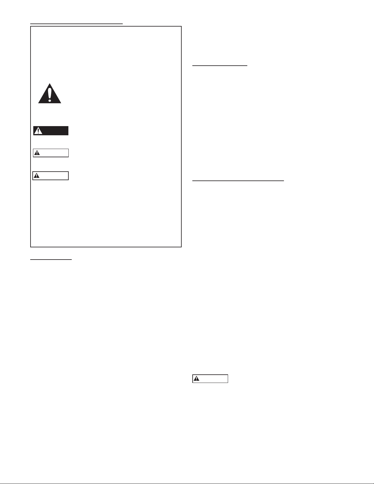
1: SAFETY INSTRUCTIONS
1: SAFETY INSTRUCTIONS
TO AVOID SERIOUS OR FATAL PERSONAL INJURY
OR MAJOR PROPERTY DAMAGE, READ AND
FOLLOW ALL SAFETY INSTRUCTIONS IN MANUAL
AND ON EQUIPMENT.
THIS MANUAL IS INTENDED TO ASSIST IN THE
INSTALLATION AND OPERATION OF THIS UNIT
AND MUST BE KEPT WITH THE UNIT.
This is a SAFETY ALERT SYMBOL.
When you see this symbol on the pump,
the controller or in the manual, look for
one of the following signal words and
be alert to the potential for personal
injury or property damage.
Warns of hazards that WILL cause
serious personal injury, death or major
property damage.
Warns of hazards that CAN cause serious
personal injury, death or major property
damage.
Warns of hazards that CAN cause
personal injury or property damage.
NOTICE: INDICATES SPECIAL
INSTRUCTIONS WHICH ARE
VERY IMPORTANT AND MUST BE
FOLLOWED.
THOROUGHLY REVIEW ALL INSTRUCTIONS
AND WARNINGS PRIOR TO PERFORMING ANY
WORK ON THIS CONTROLLER.
MAINTAIN ALL SAFETY DECALS.
In addition to proper system engineering and competent
manufacturing, the use of basin installers who have both
practical experience and integrity to assist that the basin
be installed properly constitutes the greatest protection
from catastrophic basin failure and liability exposure.
3: DISCLAIMER
3: DISCLAIMER
Every reasonable effort has been put forth by CentriPro
and its agents to ensure the accuracy and reliability
on the information contained in this reference guide.
However, neither CentriPro, its agents, nor its consultant
make any representation, warranty, or guarantee in
connection with the publication of these recommended
methods and procedures. CentriPro hereby disclaims any
liability for loss or damage resulting from their use; for
the violation of any federal, state, county, or municipal
regulations with which these recommended methods and
procedures may conflict; or for the infringement of any
patent resulting from the use of recommended methods
and procedures.
4: MATERIAL HANDLING
4: MATERIAL HANDLING
GENERAL HANDLING
Although the exterior surfaces of our fiberglass reinforced
plastic (FRP) sump and sewage basins are designed,
to withstand normal handling, they can be damaged
during transportation and installation. Basins must not
be dropped, dragged, or handled with sharp objects and
with the exception of the minimal movement involved in
a visual inspection, should not be rolled.
2: PURPOSE
2: PURPOSE
The purpose of this guide is to provide a brief reference
to the recommended methods and procedures for
installing CentriPro underground sump and sewage
basins to ensure that damage or premature failure of the
basin do not occur.
Studies conducted by both environmental regulatory
agencies and trade organizations demonstrate that
the most significant source of leaks and failures in
underground storage systems is improper handling and
installation. Proper handling and installation requires
practical experience combined with strict adherence to
proven methods and procedures.
This guide is not intended to serve as a basic instructional
manual. The installation of our sump and sewage basins
is a specialized skill, and is assumed that the individuals
who install our products and refer to this guide will have
basic understanding of such procedures as excavating,
backfilling, pipe fitting, and electrical work. No amount
of written instruction by a manufacture or a regulatory
agency will convert an inexperienced, under-supervised
laborer into a skilled, experienced mechanic. The
ability to recognize and correctly respond to abnormal
conditions during a basin installation requires field
experience as well as mechanical aptitude.
If the basin or its shell is damaged, installation should
be suspended until CentriPro or its agent can make a
determination of the extent of damage. Any repairs must
be first authorized in writing by CentriPro and than be
done in accordance with CentriPro instructions.
UNLOADING, LIFTING AND LOWERING
The proper way of moving a basin is by lifting it, using
chains or cables with the optional lifting lugs (not more
than 30* included angle) or by using a non-marring sling
around the basin. Before any attempt is made to move a
basin, it should be established that all of the equipment
and accessories have sufficient capacity and reach to lift
and lower the basins without dragging and/or dropping.
Basins should be maneuvered with guide ropes attached
to the sides.
Under NO, circumstances are the use of
chains or cables around the basin shell
permitted.
STORAGE
Basins should be stored in a secure, controlled area
where the potential for accidental damage or vandalism
will be minimized. The storage area should be free from
sharp objects, rocks and any other foreign solutions or
materials that could cause damage to the basins. Chock
3

WARNING
the basins until they are needed for installation and if
WARNING
windy conditions are possible, secure the basins with
non-marring restraints of a size and number adequate for
securing the basin.
PRE-INSTALLATION INSPECTION
Basins, vales, equipment, and piping materials should
be physically and visually inspected before installation.
Adherence to the project’s specifications should also be
confirmed before installation. If the basin or any of its
internal components are damaged, installation should be
suspended until a determination of the extent of damage
can be made by CentriPro or its agent. Any repairs must
be first authorized in writing by CentriPro and then be
done in accordance with CentriPro instructions.
WORK AREA SAFETY
Safe installation procedures shall be the sole responsibility of the basin installer. Work safety requirements are
defined in U.S. Department of Labor 29 CFR part 1926,
subpart P, Excavations.
6: BACKFILLING
6: BACKFILLING
GENERAL
Careful selection, placement, and compaction of
approved backfill material is critical to a successful basin
installation. Among the common problems associated
with basin leaks and premature failures are:
• Use of incorrect backll material
5: EXCAVATING
5: EXCAVATING
EXCAVATING
The excavation should provide adequate space for
the basin, piping, and other buried equipment and for
the replacement and compaction of backfill materials
particularly around the basin walls. The size, shape and
wall slope of the excavation should be determined by soil
conditions, depth of excavation, shoring requirements,
and if workers are required to enter the excavation,
safety considerations and federal, sate, county, and
municipal regulations.
Locate all overhead and underground
utilities before excavating.
LOCATION OF EXCAVATING
Excavation for an underground basin should be made
with due care to avoid undermining foundations of
existing structures and contact with underground
utilities. In the absence of building codes or regulations,
maintain a minimum distance of five feet plus a slope or
45* from the bottom of the compacted sub-base to the
bottom of the adjacent structures, foundations, footings,
and property lines (as shown in the attached illustration).
Additional distances may be required to assure that
any loading carried or created by the foundations and
supports cannot be transferred to the basins.
MAXIMUM BURIAL DEPTH
If burial depth is greater than the basin height, contact
CentriPro to determine if additional wall reinforcement
is required and secure written authorization.
HANDLING OF EXCAVATED MATERIALS
Excavated materials, which cannot be removed from the
job site, should be carefully stored as far from the edge of
the basin excavation as possible. Unless approved for use
as backfill, excavation materials should be securely stored
separate from the approved backfill materials.
• Inadequate or improper placement or compaction
• Rocks, clods, or debris left in the excavation or basin
• Voids under or around the perimeter of the basin
• Failure to prevent the migration of backll materials
PLACEMENT OF BASIN
The bottom of the basin excavation should be covered
with suitably with graded, leveled, and compacted
backfill material to a depth of at least 12 inches
(compacted sub-base). If a concrete hold-down/antiflotation pad is required, this bedding can be reduced
to a depth of at least 6 inches. The carefully lower the
basin into the excavation and centered on the compacted
backfill or concrete pad (see attached).
Placement of a basin on a concrete pad or
compacted sub-base smaller than the total
basin bottom area or on intermediate supports (saddles)
will cause uneven distribution of loads. This may
contribute to structural failure, and is never permitted.
BACKFILL MATERIAL
Back fill material should be clean, well granulated, free
flowing, non-corrosive, and inert. It should be free of ice,
snow, debris, rock, or organic material, all of which could
damage the tank and interfere with the compaction of
the backfill material. The largest particles should not be
larger than 3/4”. Not more than 3% (by weight) should
pass through a # 8 sieve, and the backfill material should
conform to ASTM C-33, Paragraph 9.1 requirements.
Approved backfill materials include:
• Pea Gravel, naturally rounded particles with a
minimum diameter of 1/8” and a maximum diameter
of 3/4”.
• Crushed rock, washed and free-owing angular
particles between 1/8” and 1/2” in size.
4

WARNING
WARNING
PLACEMENT AND COMPACTION OF
BACKFILL
Compaction of backfill materials should be adequate to
ensure the support of the tank, and to prevent movement
or settlement. Backfill materials should be placed in 12”
lifts and compacted to a minimum soil modulus of 700
pounds per square inch (psi).
SUPPORTING PIPING, EQUIPMENT AND
ACCESSORIES
Support for piping, equipment and other accessories
must be provided during backfilling. Using the basin to
support piping, equipment, cribbing, bracing, or blocking
is never permitted. During backfilling, temporary
supporting materials must be carefully installed and
removed to prevent damage to the basin, piping, or
equipment.
Using the basin to support any loading
carried or created by piping, equipment,
cribbing, bracing, or blocking is never permitted.
7: ANCHORAGE
7: ANCHORAGE
GENERAL
When basin installations are located in areas subject
to high water tables or flooding, provisions should be
made to prevent the basins, either empty or filled, from
floating. The buoyancy force to be offset is determined
primarily by the volume of the basin.
METHODS OF ANCHORAGE
All methods of anchoring basins use the weight of the
backfill materials to offset the buoyancy forces. The
use of supplemental mechanical anchoring methods (a
concrete hold-down pad) increases the amount of backfill
ballast, which is mechanically attached to the basin. The
recommended method of attachment is to pour concrete
grout over the basin’s anti-floatation flange and concrete
grout over the basin’s anti-floatation flange and concrete
hold-down pad (see attached illustration).
ANCHORAGE REQUIREMENTS
Requirements of anchorage, thickness of concrete
hold-down pads, as well as the size of anchors and
reinforcement must be calculated for each installation
based on the environmental conditions of that specific
installation.
Use “submerged” material weights when
calculating anchorage requirements.
Example: weight of concrete (150 ponds per cubic foot)
minus the weight of the water (62.4 pounds per cubic
foot) equals a “submerged” weight of 87.6 pounds per
cubic foot.
The principle offsetting factors include:
• Backll materials
• Concrete hold-down pad
• Friction between the tank, backll materials and the
surrounding soil
5

FIBERGLASS BASIN INSTALLATION REFERENCE GUIDE
30º Maximum
Lifting cable or chain
Spreader bar
Finish grade
Optional lifting lugs
CAUTION:
HANDLE WITH CARE
DO NOT DROP
DO NOT IMPACT
DO NOT ROLL
DO NOT WRAP
Cable or chain
around basin
Compacted sub-base
minimum 12” or 8”
when used with concrete
hold-down pad
Adjacent structure, foundation,
footing or property line
5”–0”
minimum
45”
minimum
Slope and size of excavation as
pipe area and engineer’s
specification. In the absence of
these, consider continuation of
soil, depth of excavation and
safety considerations.
Basin anti-flotation flange
Compacted sub-base and/or
concrete slab as per engineer’s
specification.
18” minimum backfill
compacted to a minimum
soil modules of 700 PSI
Finish grade
Fiberglass Basin as
required per
engineer’s
specification
In the absence of building codes, or regulations,
maintain a minimum distance of 5 feet plus a slope
of 40” from the bottom of the compacted sub-base
to the bottom of the adjacent structure’s foundation,
footing or property line.
1”
3/4”
1/2”
1/4”
Pea Gravel Crushed Brick
BACKFILL MATERIAL REQUIREMENTS
NOTE: The intent of these installation instructions and illustrations is to ensure that
damage or premature failure to the basin will not occur. These installation instructions
and illustrations are NOT intended to preclude normal safety procedures which should
be followed to prevent injury to personnel. SAFE INSTALLATION PROCEDURES SHALL
BE ENTIRELY THE RESPONSIBILTY OF THE INSTALLER.
6
Backfill material
Concrete grout as
required per
engineer’s
specification

NOTES
7

CENTRIPRO LIMITED WARRANTY
This warranty applies to all water systems pumps manufactured by CentriPro.
Any part or parts found to be defective within the warranty period shall be replaced at no charge to the dealer during the warranty period. The warranty
period shall exist for a period of twelve (12) months from date of installation or eighteen (18) months from date of manufacture, whichever period is
shorter.
A dealer who believes that a warranty claim exists must contact the authorized CentriPro distributor from whom the pump was purchased and furnish
complete details regarding the claim. The distributor is authorized to adjust any warranty claims utilizing the CentriPro Customer Service Department.
The warranty excludes:
(a) Labor, transportation and related costs incurred by the dealer;
(b) Reinstallation costs of repaired equipment;
(c) Reinstallation costs of replacement equipment;
(d) Consequential damages of any kind; and,
(e) Reimbursement for loss caused by interruption of service.
For purposes of this warranty, the following terms have these definitions:
(1) “Distributor” means any individual, partnership, corporation, association, or other legal relationship that stands between CentriPro and the dealer in
purchases, consignments or contracts for sale of the subject pumps.
(2) “Dealer” means any individual, partnership, corporation, association, or other legal relationship which engages in the business of selling or leasing
pumps to customers.
(3) “Customer” means any entity who buys or leases the subject pumps from a dealer. The “customer” may mean an individual, partnership, corporation,
limited liability company, association or other legal entity which may engage in any type of business.
THIS WARRANTY EXTENDS TO THE DEALER ONLY.
Xylem, Inc.
2881 East Bayard Street Ext., Suite A
Seneca Falls, NY 13148
Phone: (866) 325-4210
Fax: (888) 322-5877
www.xyleminc.com/brands/centripro
CentriPro is a trademark of Xylem Inc. or one of its subsidiaries.
© 2013 Xylem Inc. IMCPFIBRGL Rev 1 February 2013
 Loading...