

Page 1
OPERATING MANUAL
ON/OFF
GLP
RUN/ENTER
OC 1x0
®
®
ba31114e07 08/2014
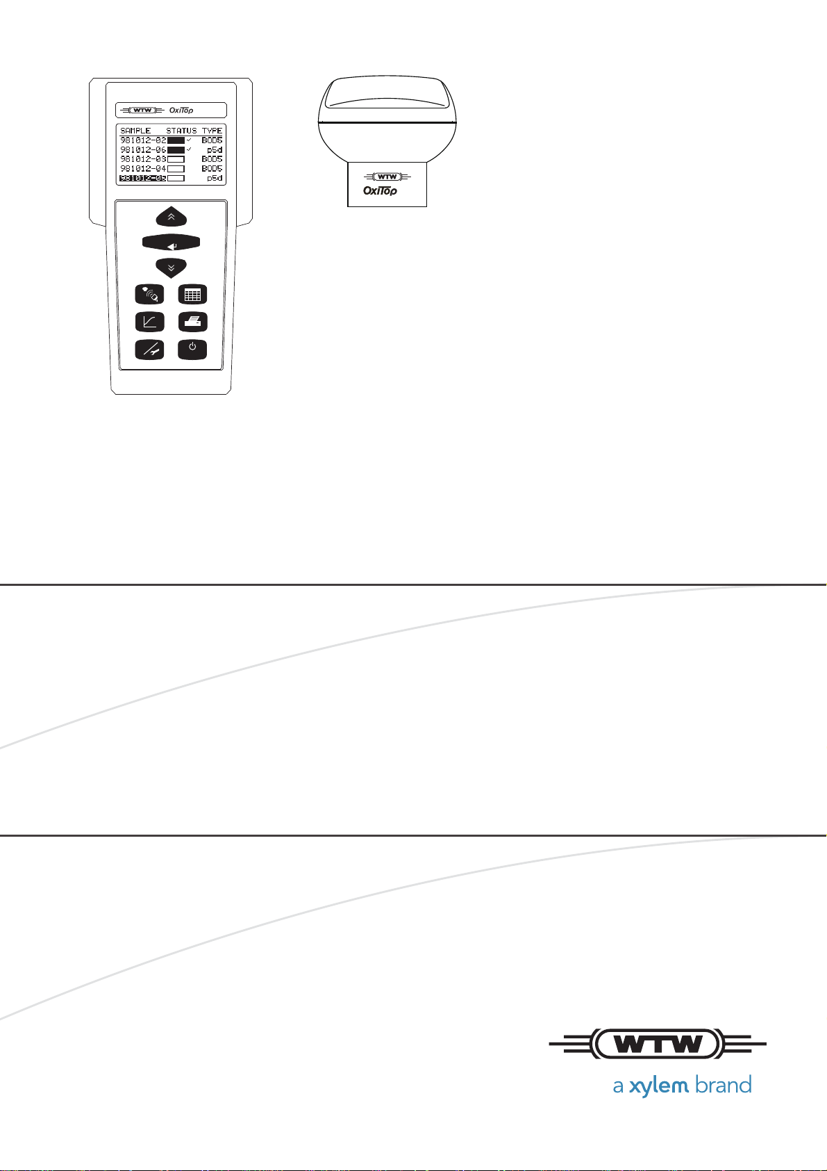
OxiTop® Control OC 100
®
OxiTop
BOD/OXYGEN CONSUMPTION: BOD, RESPIRATION, BIOGAS DETERMINATION
C or OxiTop® C/B
Page 2

Copyright © 2016 Xylem Analytics Germany GmbH
Printed in Germany.
Page 3

OxiTop® Control OC 100 Contents
OxiTop® Control OC 100 - Contents
1 Overview . . . . . . . . . . . . . . . . . . . . . . . . . . . . . . . . . . . . . . . . . . 7
1.1 The system OxiTop® Control. . . . . . . . . . . . . . . . . . . . . . . . . . . 7
1.2 The measurement principle. . . . . . . . . . . . . . . . . . . . . . . . . . . . 7
1.3 Data management. . . . . . . . . . . . . . . . . . . . . . . . . . . . . . . . . . . 8
1.4 Literature . . . . . . . . . . . . . . . . . . . . . . . . . . . . . . . . . . . . . . . . . . 8
2 Safety. . . . . . . . . . . . . . . . . . . . . . . . . . . . . . . . . . . . . . . . . . . . . 9
2.1 Safety information . . . . . . . . . . . . . . . . . . . . . . . . . . . . . . . . . . . 9
2.1.1 Safety information in the operating manual . . . . . . . . . . . 9
2.1.2 Safety signs on the meter. . . . . . . . . . . . . . . . . . . . . . . . . 9
2.2 Safe operation . . . . . . . . . . . . . . . . . . . . . . . . . . . . . . . . . . . . . . 9
2.2.1 Authorized use . . . . . . . . . . . . . . . . . . . . . . . . . . . . . . . . . 9
2.2.2 Requirements for safe operation . . . . . . . . . . . . . . . . . . . 9
2.2.3 Unauthorized use . . . . . . . . . . . . . . . . . . . . . . . . . . . . . . 10
3 Commissioning. . . . . . . . . . . . . . . . . . . . . . . . . . . . . . . . . . . . 11
3.1 Scope of delivery. . . . . . . . . . . . . . . . . . . . . . . . . . . . . . . . . . . 11
3.2 Power supply. . . . . . . . . . . . . . . . . . . . . . . . . . . . . . . . . . . . . . 11
3.2.1 Batteries . . . . . . . . . . . . . . . . . . . . . . . . . . . . . . . . . . . . . 11
3.2.2 Battery status signals . . . . . . . . . . . . . . . . . . . . . . . . . . . 11
3.2.3 Energy saving feature (automatic switch-off) . . . . . . . . . 12
3.3 Initial commissioning . . . . . . . . . . . . . . . . . . . . . . . . . . . . . . . . 12
3.3.1 Inserting the supply battery holder - controller . . . . . . . . 12
4 Operation. . . . . . . . . . . . . . . . . . . . . . . . . . . . . . . . . . . . . . . . . 15
4.1 General operating principles . . . . . . . . . . . . . . . . . . . . . . . . . . 15
4.1.1 Keys - controller . . . . . . . . . . . . . . . . . . . . . . . . . . . . . . . 15
4.1.2 Socket field - controller. . . . . . . . . . . . . . . . . . . . . . . . . . 16
4.2 Switching on . . . . . . . . . . . . . . . . . . . . . . . . . . . . . . . . . . . . . . 16
4.2.1 Switching on the controller . . . . . . . . . . . . . . . . . . . . . . . 16
4.2.2 Switching on the measuring heads. . . . . . . . . . . . . . . . . 16
4.3 Navigation . . . . . . . . . . . . . . . . . . . . . . . . . . . . . . . . . . . . . . . . 17
4.3.1 Operating modes . . . . . . . . . . . . . . . . . . . . . . . . . . . . . . 17
4.3.2 Menus, functions and dialogs. . . . . . . . . . . . . . . . . . . . . 18
4.3.3 The course of the measurement. . . . . . . . . . . . . . . . . . . 19
5 Operating mode: BOD Standard / BOD Routine . . . . . . . . . 21
5.1 Sample preparation . . . . . . . . . . . . . . . . . . . . . . . . . . . . . . . . . 21
5.2 Starting the measurement . . . . . . . . . . . . . . . . . . . . . . . . . . . . 21
5.3 Calling up all data . . . . . . . . . . . . . . . . . . . . . . . . . . . . . . . . . . 24
5.4 SAMPLE STATUS TYPE list (sample management) . . . . . . . 26
5.4.1 Showing a sample . . . . . . . . . . . . . . . . . . . . . . . . . . . . . 27
5.4.2 Erasing data of finished samples . . . . . . . . . . . . . . . . . . 28
5.4.3 Showing the measuring head list . . . . . . . . . . . . . . . . . . 29
ba31114e07 08/2014 3
Page 4

Contents OxiTop® Control OC 100
5.4.4 Calling up data . . . . . . . . . . . . . . . . . . . . . . . . . . . . . . . . 29
5.4.5 Calling up data - Stop. . . . . . . . . . . . . . . . . . . . . . . . . . . 31
5.5 Evaluation . . . . . . . . . . . . . . . . . . . . . . . . . . . . . . . . . . . . . . . . 33
5.5.1 Sample statistics (BOD Standard operating mode) . . . . 34
5.5.2 Excluding a curve (BOD Standard operating mode) . . . 35
5.5.3 Cursor interrogation . . . . . . . . . . . . . . . . . . . . . . . . . . . . 36
5.5.4 Curves display for cold samples. . . . . . . . . . . . . . . . . . . 37
5.5.5 Measured values outside the measuring range . . . . . . . 37
6 Printing . . . . . . . . . . . . . . . . . . . . . . . . . . . . . . . . . . . . . . . . . . 39
7 GLP/TOOLS. . . . . . . . . . . . . . . . . . . . . . . . . . . . . . . . . . . . . . . 41
7.1 GLP/TOOLS main menu . . . . . . . . . . . . . . . . . . . . . . . . . . . . . 41
7.2 Show free measuring heads . . . . . . . . . . . . . . . . . . . . . . . . . . 42
7.3 Show settings . . . . . . . . . . . . . . . . . . . . . . . . . . . . . . . . . . . . . 42
7.4 Settings . . . . . . . . . . . . . . . . . . . . . . . . . . . . . . . . . . . . . . . . . . 43
7.4.1 Operating mode . . . . . . . . . . . . . . . . . . . . . . . . . . . . . . . 43
7.4.2 Operational life . . . . . . . . . . . . . . . . . . . . . . . . . . . . . . . . 44
7.4.3 Date/time . . . . . . . . . . . . . . . . . . . . . . . . . . . . . . . . . . . . 45
7.4.4 GLP (Operating mode BOD Standard ) . . . . . . . . . . . . . 45
7.4.5 GLP - calibration interval (- Calinterval) . . . . . . . . . . . . . 46
7.4.6 Data storage. . . . . . . . . . . . . . . . . . . . . . . . . . . . . . . . . . 47
7.4.7 AutoTemp. . . . . . . . . . . . . . . . . . . . . . . . . . . . . . . . . . . . 47
7.4.8 Switch-off interval. . . . . . . . . . . . . . . . . . . . . . . . . . . . . . 49
7.4.9 Language . . . . . . . . . . . . . . . . . . . . . . . . . . . . . . . . . . . . 50
7.5 Check. . . . . . . . . . . . . . . . . . . . . . . . . . . . . . . . . . . . . . . . . . . . 51
7.5.1 Showing the measuring heads. . . . . . . . . . . . . . . . . . . . 51
7.5.2 Measuring head information. . . . . . . . . . . . . . . . . . . . . . 51
7.5.3 Controller information. . . . . . . . . . . . . . . . . . . . . . . . . . . 53
7.5.4 cal-test . . . . . . . . . . . . . . . . . . . . . . . . . . . . . . . . . . . . . . 53
7.5.5 Pneumatic test . . . . . . . . . . . . . . . . . . . . . . . . . . . . . . . . 55
7.6 Maintenance . . . . . . . . . . . . . . . . . . . . . . . . . . . . . . . . . . . . . . 56
7.6.1 Erasing finished samples . . . . . . . . . . . . . . . . . . . . . . . . 57
7.6.2 Reset/release . . . . . . . . . . . . . . . . . . . . . . . . . . . . . . . . . 59
7.6.3 Reading out data . . . . . . . . . . . . . . . . . . . . . . . . . . . . . . 60
8 Transmitting data . . . . . . . . . . . . . . . . . . . . . . . . . . . . . . . . . . 62
8.1 Achat OC software. . . . . . . . . . . . . . . . . . . . . . . . . . . . . . . . . . 62
9 Maintenance, cleaning, disposal. . . . . . . . . . . . . . . . . . . . . . 63
9.1 Maintenance . . . . . . . . . . . . . . . . . . . . . . . . . . . . . . . . . . . . . . 63
9.1.1 General maintenance activities . . . . . . . . . . . . . . . . . . . 63
9.1.2 Replacing the supply batteries (controller). . . . . . . . . . . 63
9.1.3 Replacing the data backup battery (controller). . . . . . . . 65
9.1.4 Changing the supply battery (measuring head) . . . . . . . 67
9.2 Cleaning. . . . . . . . . . . . . . . . . . . . . . . . . . . . . . . . . . . . . . . . . . 68
9.2.1 Cleaning of the sample bottles. . . . . . . . . . . . . . . . . . . . 68
9.2.2 Cleaning of the controller and measuring heads . . . . . . 68
9.3 Disposal. . . . . . . . . . . . . . . . . . . . . . . . . . . . . . . . . . . . . . . . . . 68
4 ba31114e07 08/2014
Page 5

OxiTop® Control OC 100 Contents
10 What to do if.... . . . . . . . . . . . . . . . . . . . . . . . . . . . . . . . . . . . . 69
10.1 Display messages . . . . . . . . . . . . . . . . . . . . . . . . . . . . . . . . . . 69
10.2 Display messages on the charging status of the batteries . . . 74
10.2.1 Batteries in the controller . . . . . . . . . . . . . . . . . . . . . . . . 74
10.2.2 Battery in the measuring head . . . . . . . . . . . . . . . . . . . . 74
10.3 General information. . . . . . . . . . . . . . . . . . . . . . . . . . . . . . . . . 75
11 Technical data. . . . . . . . . . . . . . . . . . . . . . . . . . . . . . . . . . . . . 79
11.1 Controller OxiTop® OC 100. . . . . . . . . . . . . . . . . . . . . . . . . . . 79
11.2 Measuring head OxiTop
®
-C or OxiTop®-C/B . . . . . . . . . . . . . 80
ba31114e07 08/2014 5
Page 6

Contents OxiTop® Control OC 100
6 ba31114e07 08/2014
Page 7

OxiTop® Control OC 100 Overview
2
0
m
l
lt
m
2
Op
T
T
V
VV
TR
OM
BOD
M(O2) Molecular weight (32000 mg/mol)
R Gas constant (83.144 lmbar/molK)
T
0
Reference temperature (273.15 K)
T
m
Measuring temperature
V
t
Bottle volume (nominal volume in ml)
V
l
Sample volume in ml
a Bunsen absorption coefficient (0.03103)
p(O
2
) Difference of the D. O. partial pressure (mbar)
1 Overview
1.1 The system OxiTop
®
Control
The classical application field for the OxiTop® measuring heads and controller
is the BODx determination (BODx = Biochemical Oxygen Demand for the time
x). The evaluation of biological degradability (e.g. test according to OECD
301F) is also part of this field.
With different sample vessels, the OxiTop
®
measuring heads and the OxiTop®
Controller 110 can also be used for other applications such as:
Evaluation of respiration and toxicity in earth, sludge, waste and sediment
(e.g. extraction of contaminated earth according to recovery concepts)
Evaluation of the respiration rate of cell cultures
Microbiological growth and stress examinations
Measurement of anaerobic degradation processes (e.g. biogas determina-
tion with the measuring head OxiTop
®
-C/B)
Accessories: see WTW catalog and price list
1.2 The measurement principle
The respirometric measurement is a pressure measurement. If oxygen is
consumed in a closed vessel at a constant temperature, a negative pressure
develops. If a gas is released, an overpressure develops. The OxiTop
measuring head measures and stores this pressure for the whole duration of a
measurement once started.
®
The OxiTop
OC 100 controller collects the pressure values from the
measuring heads and processes them.
The formula shown below is the basis for all calculations for the BOD using the
®
values from the OxiTop
measuring head.
®
ba31114e07 08/2014 7
Page 8

Overview OxiTop® Control OC 100
The interpretation of the pressure differences in the temporal course depends
on the measured material and its preparation and on the sample manipulation
(e. g. intermediate aerations) during the measuring period.
1.3 Data management
The measuring head records the measured values and stores the measuring
data. Using the controller, the collected and stored data are read out from the
measuring head and stored in the “sample management“. Starting at the
OxiTop
®
sample management, it is possible to make the graphical and statis-
tical evaluation of the sample data.
The data can be transferred from the controller to a computer via the RS232
interface. The read-out software Achat OC facilitates to process the stored data
further.
Additionally, the data can be transferred to an IR printer via the IR interface.
1.4 Literature
Further information and application reports on the subject of measuring with the
system OxiTop
CD-ROM Applications for OxiTop
®
Control can be obtained at no cost from WTW:
®
Control
CD-ROM Principles of measuring technique
8 ba31114e07 08/2014
Page 9
OxiTop® Control OC 100 Safety
2 Safety
2.1 Safety information
2.1.1 Safety information in the operating manual
This operating manual provides important information on the safe operation of the instrument. Read this operating manual thoroughly and
make yourself familiar with the instrument before putting it into operation or working with it. The operating manual must b e kept in the vicinity
of the instrument so you can always find the information you need.
Important safety instructions are highlighted in this operating manual.
They are indicated by the warning symbol (triangle) in the left column.
The signal word (e.g. "CAUTION") indicates the danger level:
WARNING
indicates a possibly dangerous situation that can lead to serious (irreversible) injury or death if the safety instruction is not
followed.
CAUTION
indicates a possibly dangerous situation that can lead to slight
(reversible) injury if the safety instruction is not followed.
NOTE
indicates a possibly dangerous situation where goods might be
damaged if the actions mentioned are not taken.
2.1.2 Safety signs on the meter
Note all labels, information signs and safety symbols on the instrument.
A warning symbol (triangle) without text refers to safety information in
this operating manual.
2.2 Safe operation
2.2.1 Authorized use
Only the operation and running of the instrument according to the
instructions and technical specifications given in this operating manual
is authorized (see section 11 T
ECHNICAL DATA, page 79).
Any other use is considered unauthorized.
2.2.2 Requirements for safe operation
Note the following points for safe operation:
• The instrument may only be operated according to the authorized
ba31114e07 08/2014 9
Page 10

Safety OxiTop® Control OC 100
use specified above.
• The instrument may only be supplied with power by the energy
sources mentioned in this operating manual.
• The instrument may only be operated under the environmental
conditions mentioned in this operating manual.
• The instrument may only be opened if this is explicitly described in
this operating manual (example: Changing the batteries).
2.2.3 Unauthorized use
The instrument must not be put into operation if:
• it is visibly damaged (e.g. after being transported)
• it was stored under adverse conditions for a lengthy period of time
(storing conditions, see section 11 T
ECHNICAL DATA, page 79).
10 ba31114e07 08/2014
Page 11

OxiTop® Control OC 100 Commissioning
3 Commissioning
3.1 Scope of delivery
Controller OxiTop® OC 100
Battery holder with batteries (3 x Mignon, AA, AM3, LR6)
Operating manual
Additional scope of delivery: depending on set composition
3.2 Power supply
The controller OxiTop® OC 100 and measuring head OxiTop®-C or OxiTop®C/B are both battery-powered.
Additionally, the controller has a data backup battery. This battery ensures that
your measuring data and instrument settings are stored in the controller
OxiTop
®
OC 100.
3.2.1 Batteries
Controller Power supply 3 alkaline batteries (alkali manganese),
Size: Mignon, AA, AM3, LR6
Runtime: > 100 h
(approx. 1000 start-ups in normal use)
Data backup 1 x lithium battery CR2430 (accessory).
Runtime: typically 4 years
Measuring
head
Power supply Batteries: 2 x lithium battery CR2430 (accessory).
Runtime: typically 2 years
3.2.2 Battery status signals
®
The OxiTop
-OC 100 controller and the OxiTop® measuring heads are powered by batteries. A low battery status of the controller or measuring head is
automatically indicated by a display message and a signal tone after the instrument is switched on (see section 10.2 D
STATUS OF THE BATTERIES, page 74).
ISPLAY MESSAGES ON THE CHARGING
1st level (warning level) Battery LoBat !
2nd level (error level) Battery empty !
The current battery status can also be queried in the menu:
Controller: Menu GLP/TOOLS - Check - Controller Info
Measuring head: Menu GLP/TOOLS -Check - info
ba31114e07 08/2014 11
Page 12
Commissioning OxiTop® Control OC 100
LISTED 8F93
LaboratoryEquipment
E163694
This device complies with Part 15 of the FCC Rules. Operation
is subject to the following conditions: (1)This devise may not
cause harmful interference, and (2) this devise must accept
any interference received, including interference that may
cause undesired operation.
Ser.-Nr.:05150013
OxiTop OC 1x0
WTW 82362 Weilheim
Made in Germany
1x CR 2430 Lithium
3xAlkaline, AA size, 1,5V
1
1
1
1
3.2.3 Energy saving feature (automatic switch-off)
The instrument switches off automatically following the last key actuation after
expiry of the specified switch-off interval.
To specify the switch-off interval: see section 7.4.8 S
WITCH-OFF INTERVAL, page
49.
3.3 Initial commissioning
Perform the following activities:
Insert the supply battery holder in the controller (see section 3 .3.1 I
THE SUPPLY BATTERY HOLDER - CONTROLLER, page 12)
Switch on the instrument
Set the date and time (see section 7.4 S
ETTINGS, page 43)
3.3.1 Inserting the supply battery holder - controller
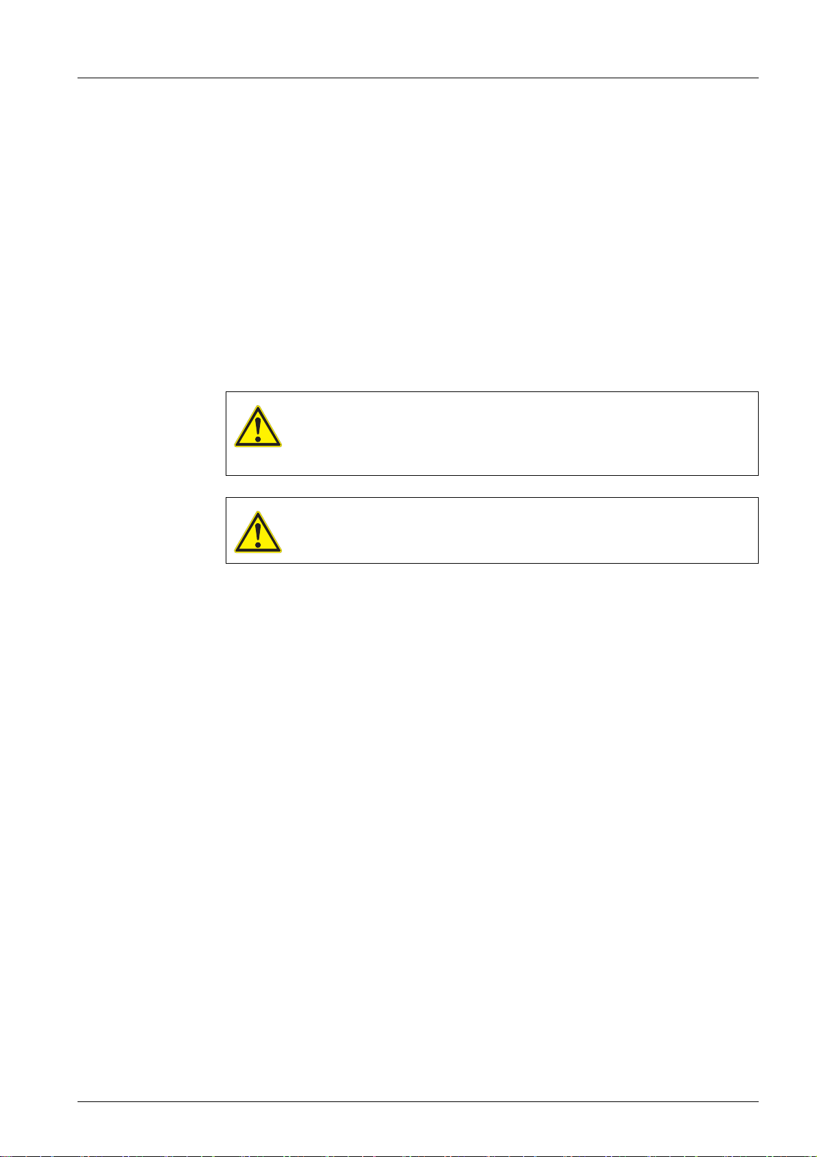
Loosen the 4 screws underneath the housing using a Phillips screwdriver.
NSERTING
1Screws
Place the controller on the lower case.
Remove the upper case and put it down to the right next to the lower case
with the display downwards.
Connect the supply battery holder with the power supply contacts of the
upper case.
Insert the supply battery holder in the lower case with the open side down.
12 ba31114e07 08/2014
Page 13
OxiTop® Control OC 100 Commissioning
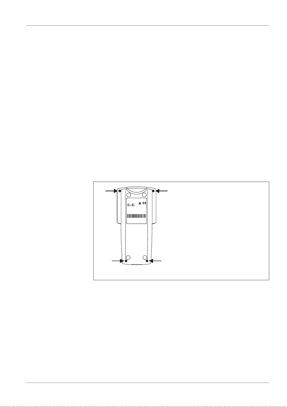
1
2
1 Supply batteries in the battery holder (lower case)
2 Data backup battery (upper case)
Set the upper case on top of the lower case, turn the controller and tighten
the housing screws using the screwdriver.
Switch on the controller. The battery insertion was successful if no error
message appears concerning the supply batteries.
ba31114e07 08/2014 13
Page 14

Commissioning OxiTop® Control OC 100
14 ba31114e07 08/2014
Page 15
OxiTop® Control OC 100 Operation
ON/OFF
GLP
RUN/ENTER
1
2
5
34
7
8
6
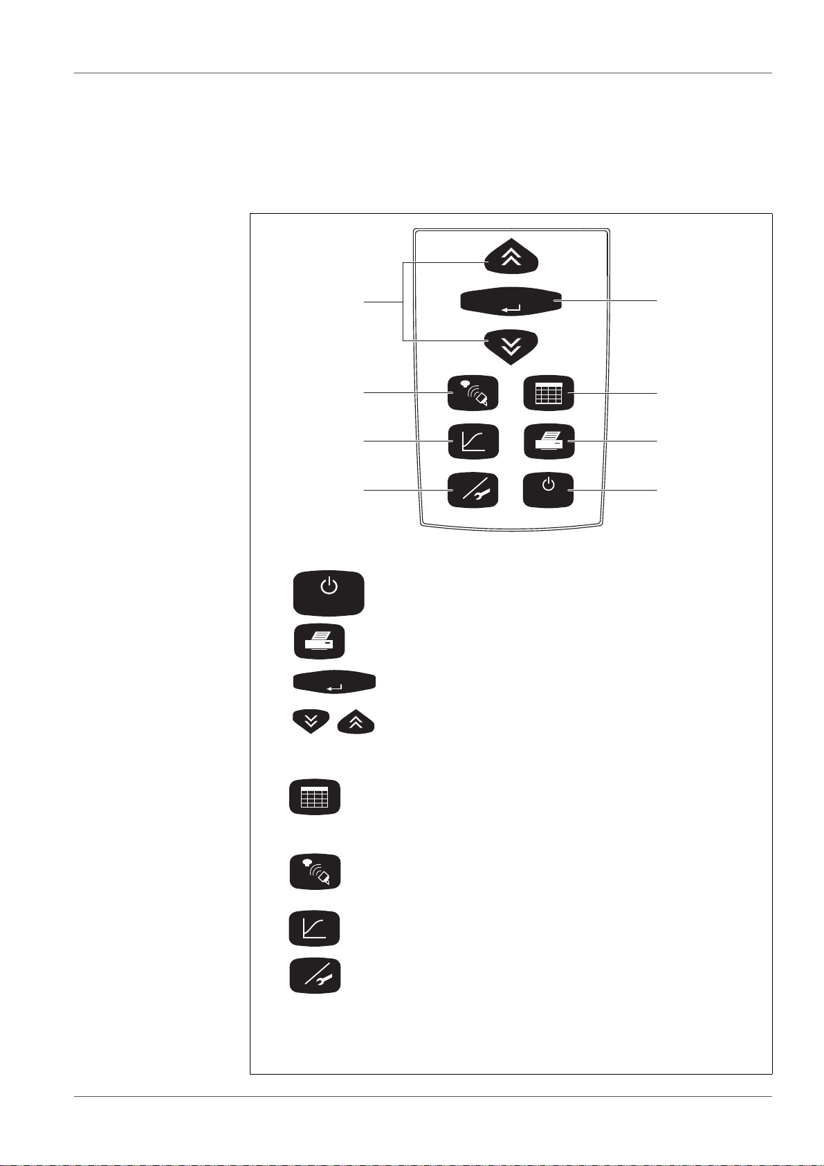
The function keys are used to start a function or to change to another
function. Confirmed data and settings are preserved.
1 <On/Off> Switching on/off
2 <PRINT> Printing of measurement data and set-
tings via IR interface
3 <RUN/
ENTER>
Confirmation of entries
4<><> Select and change settings
Function keys:
5 <ORG> Sample management: List of samples,
reading/calling up/deleting the data of individual measuring heads or samples,
shows measuring heads or samples
6 <COMM> Communication with measuring heads:
Start measuring, change or show settings,
call up data
7 <GRAPH> Evaluation: Graphic and numerical dis-
play of measuring data
8 <GLP> GLP/Tools: Change or display settings,
display free measuring heads, display or
change settings, perform checks or maintenance
ON/OFF
RUN/ENTER
GLP
4Operation
4.1 General operating principles
4.1.1 Keys - controller
ba31114e07 08/2014 15
Page 16
Operation OxiTop® Control OC 100
1
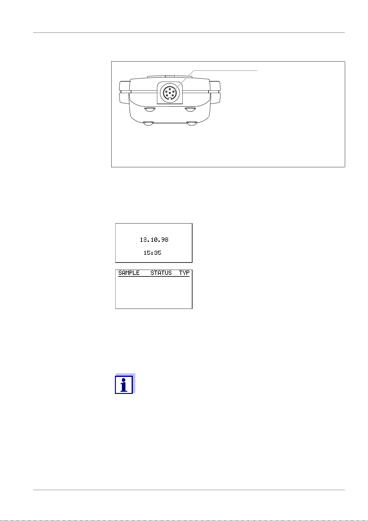
4.1.2 Socket field - controller
1 RS232 interface
The RS232 interface is used for communication with the PC. Usage
of the RS232 interface is exclusively intended with the WTW software
"Achat OC“ (see section 8.1 A
CHAT OC SOFTWARE, page 62).
4.2 Switching on
4.2.1 Switching on the controller
The current date and time appear for approx. 2
seconds (important for the allocation of sample
numbers).
If the date or time is wrong, correct them under
GLP/TOOLS.
The instrument is in the sample management
mode (operating mode BOD Routine , in the
default condition).
4.2.2 Switching on the measuring heads
The measuring heads are immediately ready for operation. The controller
switches the measuring heads on and off during communication.
To avoid malfunctions:
If you use two or more controllers simultaneously make sure that
the distance between the controllers is at least 3 meters!
16 ba31114e07 08/2014
Page 17

OxiTop® Control OC 100 Operation
4.3 Navigation
4.3.1 Operating modes
BOD Routine:
(preselected)
Measurement of single samples for a BOD
(x = 0.5h ... 99d) at 20 °C
x
The measuring range and filling volume can be selected out of seven per-
manent ranges and the corresponding filling volumes.
The function is permanently switched on
BOD Standard: Measurement of up to 12 parallel sample processes per overall sample for
a BOD
(x = 0.5h ... 99d) at 20 °C
x
The measuring range and filling volume can be selected out of seven per-
manent ranges and the corresponding filling volumes.
Automatic sample statistics with averaging
The AutoTemp function and the GLP mode can be switched on
ba31114e07 08/2014 17
Page 18

Operation OxiTop® Control OC 100
4.3.2 Menus, functions and dialogs Example: Pressing the <COMM> button causes the controller to change to the
SELECT ACTION menu (communication with the measuring heads).
Signal tone
Action:
Press button. The instrument displays:
This symbol in the operating manual means:
A signal tone sounds.
Description of what the
action caused and possible
further request:
SELECT ACTION menu
(communication with the measuring heads):
Preselected: - Start sample.
Select a menu item with
<><>.
The selected function or line is
displayed in inverse video.
Confirm the menu item with
<RUN/ENTER>.
The submenu is opened or the
function is carried out.
Measuring head Each measuring head that receives a command from the controller indicates
this by a short flashing signal.
®
The OxiTop
measuring head is indicated by the symbol
18 ba31114e07 08/2014
Page 19
OxiTop® Control OC 100 Operation
GLP
Time
End of measurement
Start of
measurement
AutoTemp
Measurement
Data transfer
Starting the
measuring
heads
Sample
management
Evaluation
Print
Print
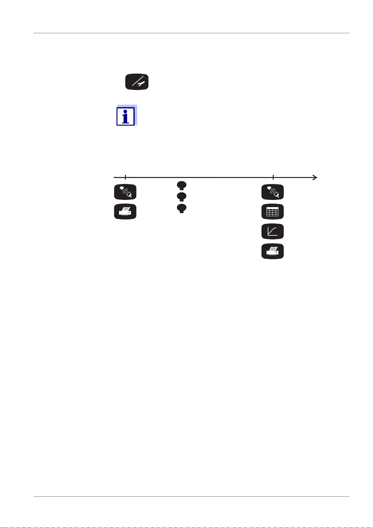
4.3.3 The course of the measurement
Preparation before
starting the mea-
surement
Measuring
Select operating mode
Select settings
Operating mode and settings cannot be changed for a measurement once it is started!
ba31114e07 08/2014 19
Page 20

Operation OxiTop® Control OC 100
20 ba31114e07 08/2014
Page 21
OxiTop® Control OC 100 Operating mode: BOD Standard / BOD Routine
RUN/ENTER
5 Operating mode: BOD Standard / BOD Rou-
tine
The BOD Standard mode (parallel sample process for up to 12 measuring
heads per overall sample) is preset in the delivery condition of the controller.
To change to the BOD Routine operating mode (single samples): see section
7.4.1 O
The handling of controller and measuring heads is basically the same in both
operating modes. Where there are differences for the BOD Routine operating
mode they are described.
5.1 Sample preparation
See application reports.
Screw the OxiTop
close them tightly.
PERATING MODE, page 43.
®
measuring heads onto the measuring vessels and
NOTE
Never use joint grease or other lubricants for your OxiTop
®
measuring
heads. Some of these products contain solvents that can cause severe
damage to the plastic housing of the measuring head.
The sealing of the measuring vessels is perfectly adequate without
grease. However, you should always wipe off heavy contamination and
®
particles on the sealing surfaces of the rubber sleeves and OxiTop
measuring heads. WTW accepts no liability for damage due to the use of
joint grease.
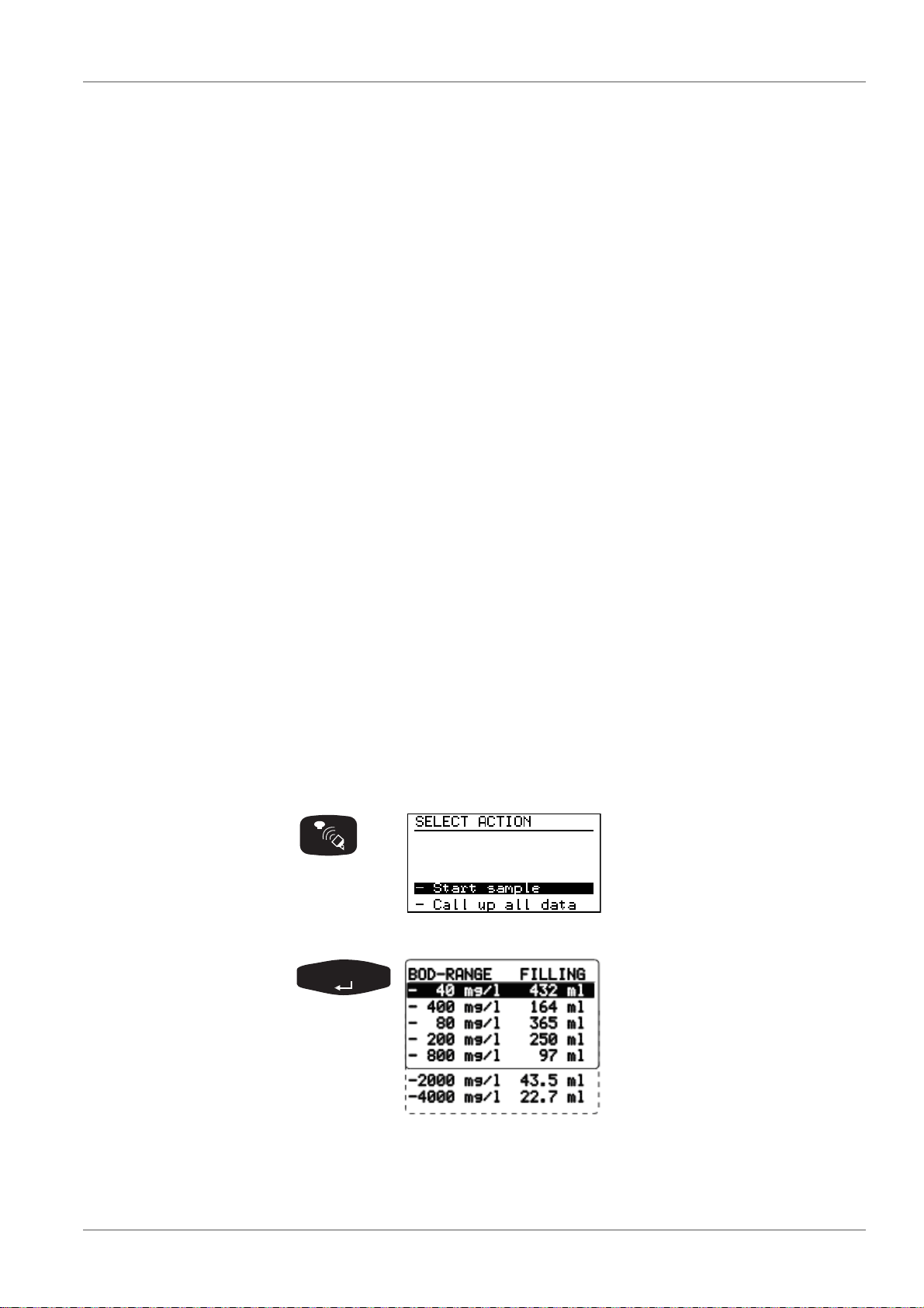
5.2 Starting the measurement
SELECT ACTION menu (communication with the measuring
heads):
Preselected: - Start sample.
(In BOD Routine mode appears:
START).
Select the measuring range with
<><>.
The filling volume required is
given in the right hand column.
The controller stores the setting
(memory function: the last
selected measurement range is
set).
ba31114e07 08/2014 21
Page 22
Operating mode: BOD Standard / BOD Routine OxiTop® Control OC 100
RUN/ENTER
RUN/ENTER
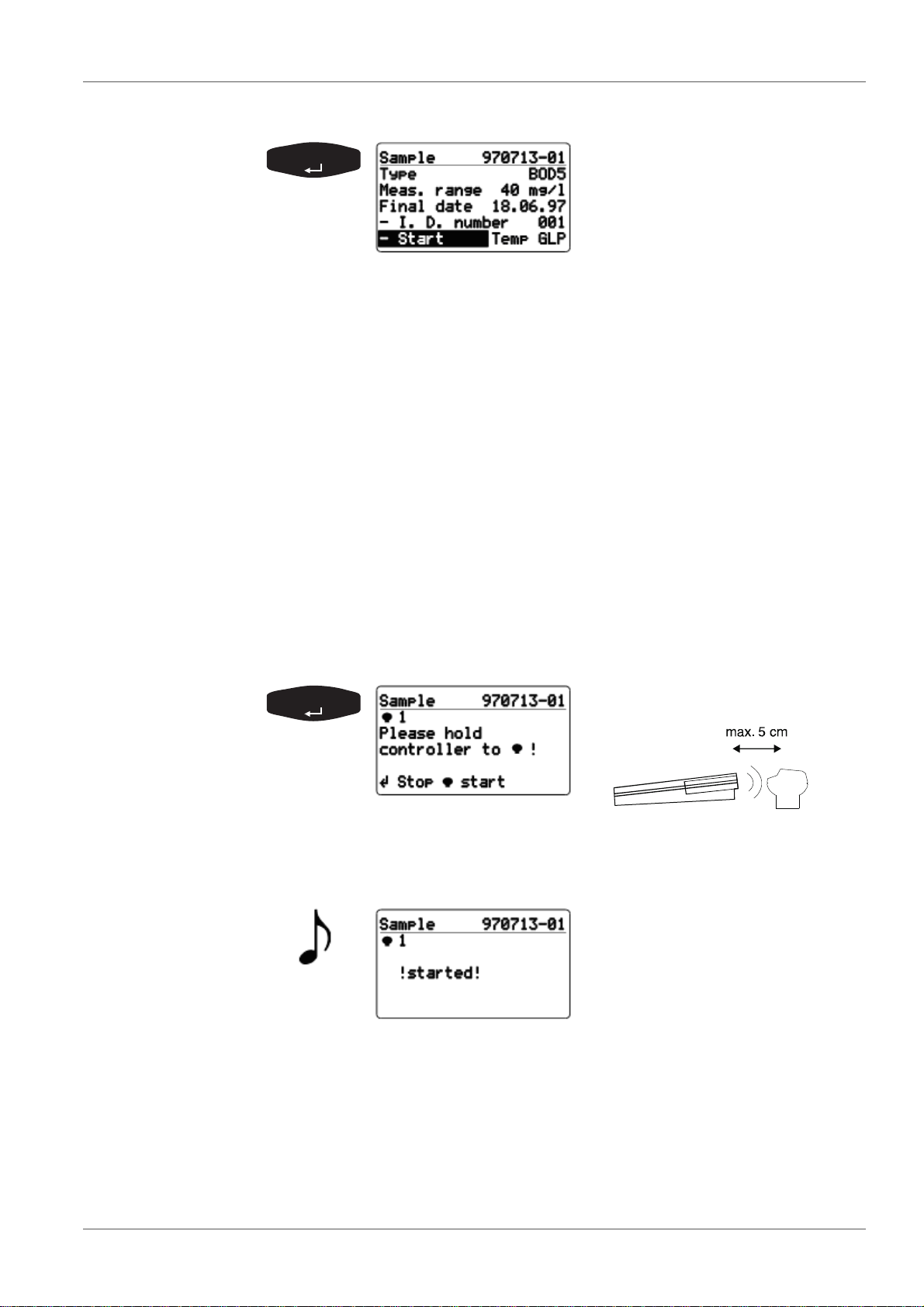
Confirm the selected measurement range for the sample. The
automatically assigned sample
number (YY/MM/DD and
sequential number) is given in
the header line.
Additional information:
Type of measurement, run duration, measurement range,
final date, ID number.
Temp display => the AutoTemp function (see section 7.1
GLP/TOOLS
MAIN MENU, page 41) is switched on.
GLP display => the GLP function (see section 7 GLP/
TOOLS, page 41) is switched on.
Change the ID number for the additional identification of the
sample (e.g. sampling location) as follows:
Select the - I.D. number menu item with <><>
Confirm with <RUN/ENTER>.
Set the required Id number (setting range 001 ... 255) with
<><>.
Confirm with <RUN/ENTER>.
Use <PRINT>
(in BOD Routine mode only), see section 6 P
to print out the entire sample information
RINTING, page
39).
Confirm the start of measure-
ment. Contact selection:
The controller repeatedly sends the start information in the
scanner mode until feedback is successfully received from the
OxiTop
®
measuring head. After the successful start message
from the measuring head:
Displays ! started !
From this
point in time, the sample exists
within the SAMPLE STATUS
TYPE list (sample manage-
ment).
Subsequently, the request to
start the next measuring head is
made automatically.
In BOD Routine operating mode there is no 1... identifier in
the display, and the
controller automatically returns to the entry menu after starting
the measuring head.
22 ba31114e07 08/2014
Page 23
OxiTop® Control OC 100 Operating mode: BOD Standard / BOD Routine
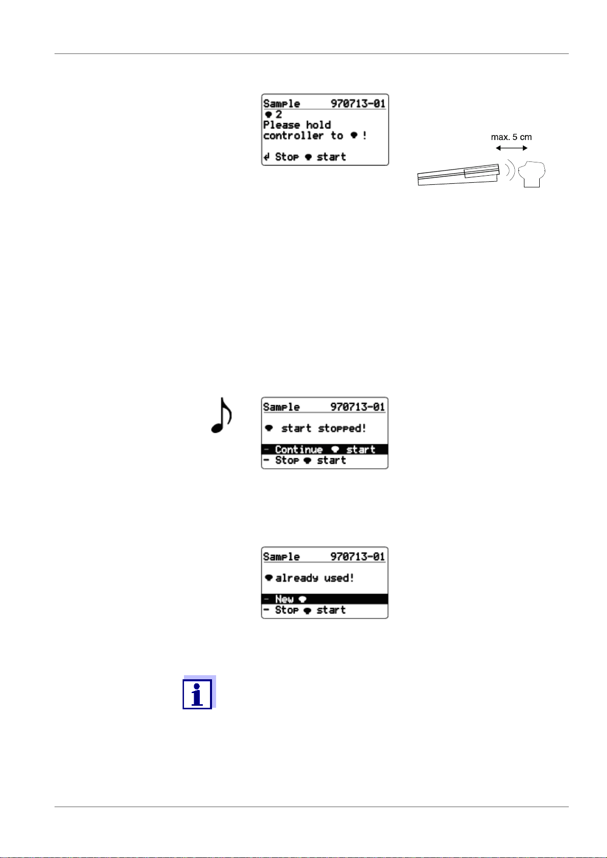
Start the next measuring head
(2).
Contact selection:
The number of the measuring
head is automatically incremented.
The controller continues to work with the contact selection, i.e.
you can now start a sequence of measuring heads (parallel
sample process) without having to press any further keys by
holding the controller to the next measuring head to be
started.
When all the measuring heads provided for this sample have
been started:
Confirm Stop start with <RUN/ENTER>.
The controller returns to the entry menu.
If no measuring head is started (e.g. because the controller
was not held to - or not close enough to - a measuring head):
The start was stopped.
Use <RUN/ENTER> - Continue
start to confirm “Continue
start” and hold the controller to a
measuring head (see above).
Return to entry level menu with
-Stop start
If an attempt is made to start a measuring head that was
already started:
Displays already used!
Use <RUN/ENTER> to confirm -
New and hold the controller
to a free measuring head (see
above).
Return to entry level menu with
-Stop start
In the delivery state, the controller automatically makes space when
Start is selected if the measured value memory is full.
To do this, it deletes the oldest finished sample (if a finished sample
is available). You can change this setting to “manual erase” (see
section 7.4.6 D
ATA STORAGE, page 47).
ba31114e07 08/2014 23
Page 24
Operating mode: BOD Standard / BOD Routine OxiTop® Control OC 100
40 cm to 1 m
RUN/ENTER
5.3 Calling up all data
This function is used to call up the data of all measuring heads, no
matter in which operating mode they were started.
To call up the data of individual measuring heads: see section 5.4
SAMPLE STATUS TYPE
LIST (SAMPLE MANAGEMENT), page 26.
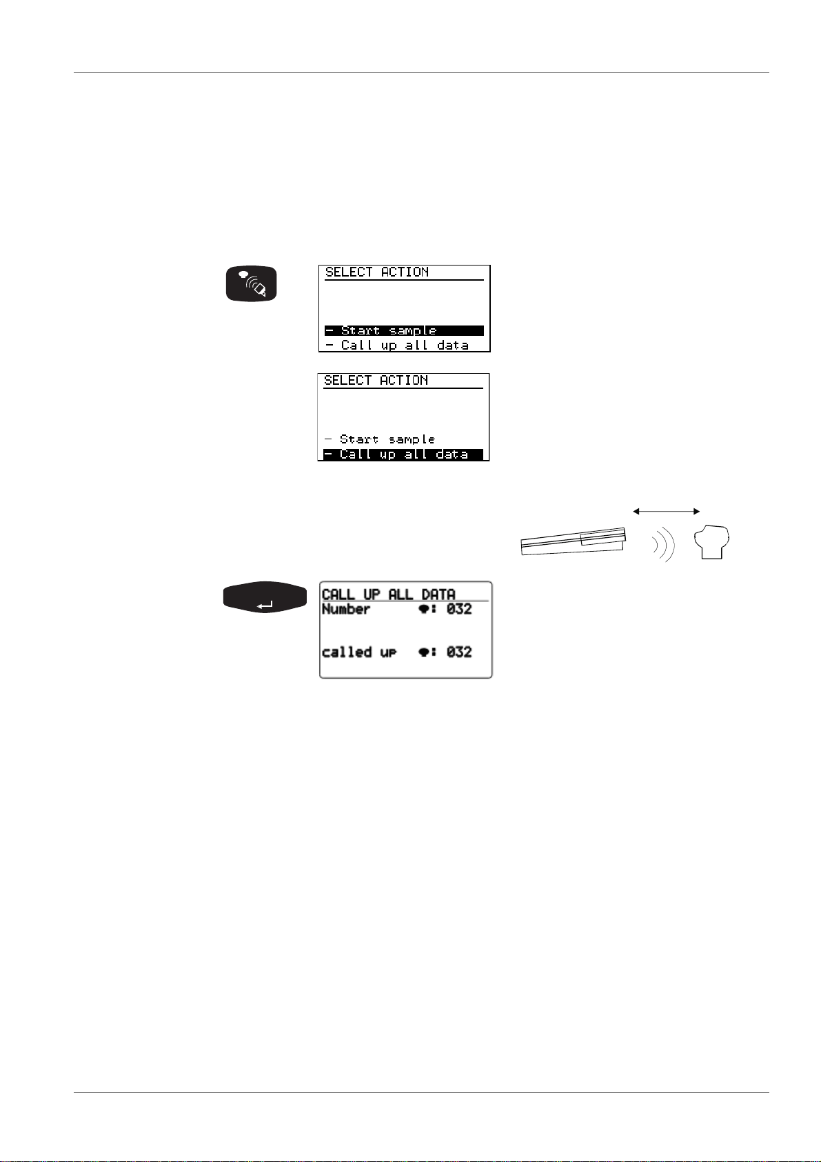
SELECT ACTION menu (communication with the measuring
heads):
Preselected: - Start sample.
Select the - Call up all data menu
item with <><>
Point the controller at the measuring
heads:
Queries the data of all active
measuring heads in the scanner
mode.
The controller stores the data
obtained and updates the
SAMPLE STATUS TYPE list
(sample management).
Duration of a pass: approx. 3
seconds for 12 measuring heads
in a stirring system.
If the measuring heads do not all respond in the 1st pass of the data query,
the controller searches for the missing measuring heads in the scanner mode
for approximately a further 7 seconds. Without having to press another key,
you can continue the data queries at other locations (e.g. other stirring platforms or other thermal cabinets).
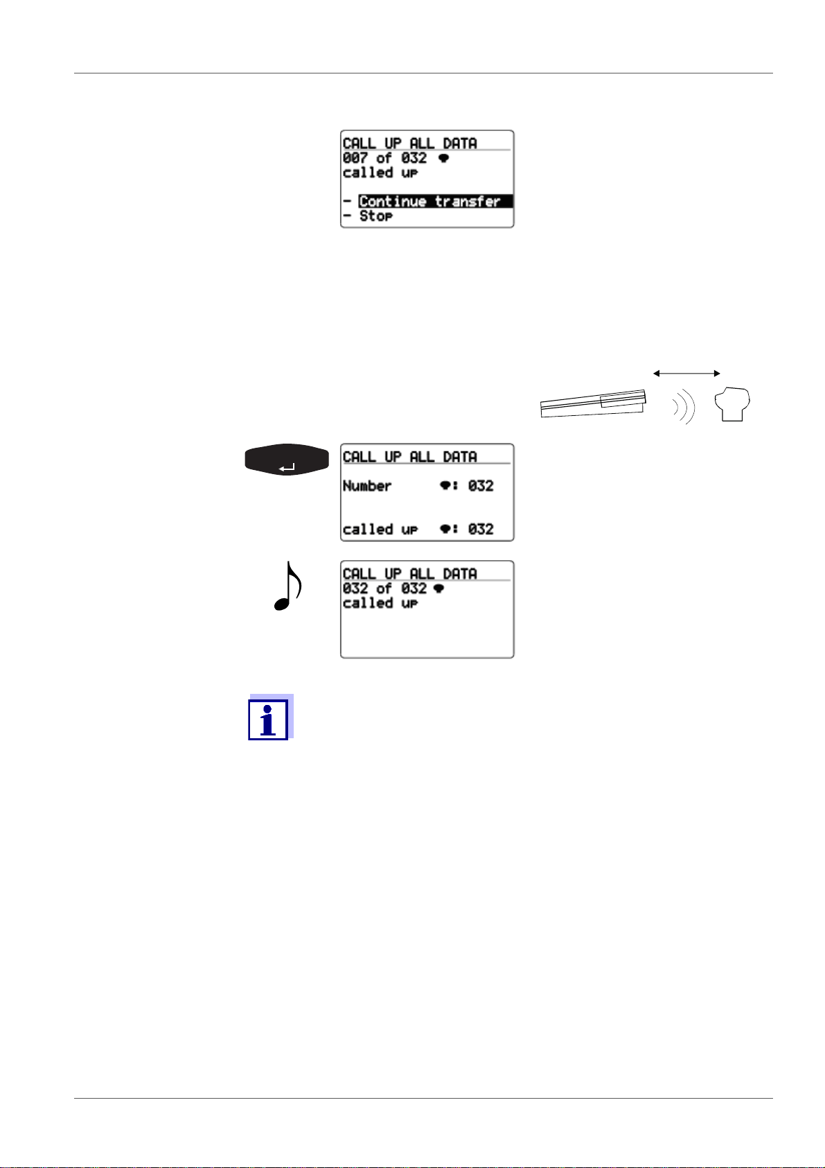
Approximately 7 seconds after the last call up was performed, the scanner
mode breaks off automatically and the following display appears:
24 ba31114e07 08/2014
Page 25
OxiTop® Control OC 100 Operating mode: BOD Standard / BOD Routine
40 cm to 1 m
RUN/ENTER
Preselected:
- Continue transfer:
A new pass is made only for
measuring heads that have not
yet responded.
Return to the entry menu with -
Stop
For information on searching for
missing measuring heads, see
section 10 W
HAT TO DO IF..., page
69
Point the controller at the measuring
heads:
The call up of further measuring
heads is performed in the scanner mode.
Message that all the data of all
the measuring heads has been
called up. The instrument then
returns to the entry menu.
Immediately after the complete measurement data records of a finished measurement have been called up, the corresponding measuring head is given the free status. The measuring head can be
used for a new measurement. The relevant sample in the
SAMPLE STATUS TYPE list (sample management) is marked as
finished (see section 5.4 SAMPLE STATUS TYPE
MANAGEMENT), page 26), as soon as the measurement time has
LIST (SAMPLE
expired and the data of all measuring heads of this sample have
been called up.
ba31114e07 08/2014 25
Page 26
Operating mode: BOD Standard / BOD Routine OxiTop® Control OC 100
3
2
1
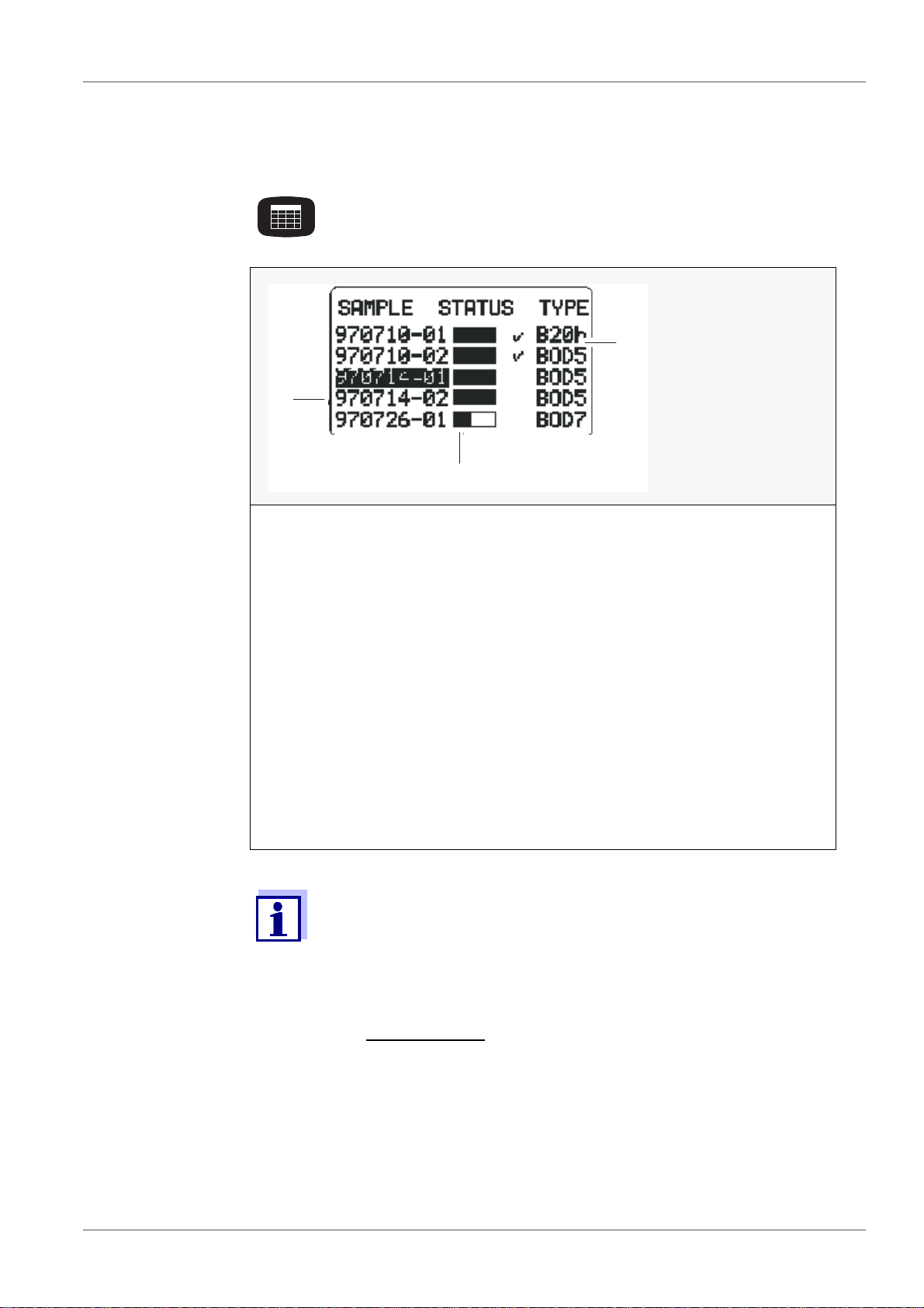
5.4 SAMPLE STATUS TYPE list (sample management)
Entry into the sample management.
A list of samples appears in the display (if samples are available):
1 Sample number:
Date (JJ/MM/TT) and consecutive number
2 Temporal process of the sample:
– Status bar partly filled:
The sample is not yet ready.
– Status bar filled:
The ready and complete data set of the sample can be called up
from the measuring head.
– Status bar filled plus checkmark:
The sample is ready. The complete data set is given in the controller for evaluation.
3 BOD type and run duration.
– B20h: BOD with 20 hours run duration
– BOD5: BOD with 5 days run duration
The samples started in the BOD Routine operating mode also
appear in the SAMPLE STATUS TYPE lists (sample management)
of all other modes. Data of samples that have been started in other
operating modes do not appear in the sample management of the
BOD Routine operating mode.
Reporting order:
At the upper end of the list: finished samples (if available)
Under this: current samples
Sorting of the samples:
according to date and sequential number 01 ... 99,
from the oldest to the newest sample.
26 ba31114e07 08/2014
Page 27

OxiTop® Control OC 100 Operating mode: BOD Standard / BOD Routine
RUN/ENTER
40 cm to 1 m
RUN/ENTER
Select a sample.
According to the sample selected, one of the two following
menus appears.
Finished sample Current sample
The header line contains the following data of the selected
sample:
Sample number
ID number (e.g. I001)
BOD type and run duration.
5.4.1 Showing a sample
This function is used to find the measuring heads or samples. Sample
labeling is not necessary.
Point the controller at the measuring
heads:
SAMPLE STATUS TYPE list
(sample management)
Use <><> to select a sample.
Select the -Show sample menu
item with <><>
The controller transmits the call
up of the selected sample. The
allocated measuring heads flash
for approx. 5 seconds.
After the message, the controller automatically returns to the
previous menu.
ba31114e07 08/2014 27
Page 28

Operating mode: BOD Standard / BOD Routine OxiTop® Control OC 100
RUN/ENTER
RUN/ENTER
RUN/ENTER
5.4.2 Erasing data of finished samples
This function erases the data of finished samples from the
SAMPLE STATUS TYPE list ( sample management) of the controller.
You can only erase a sample if it is finished; in non-finished samples,
the menu item -Erase sample does not appear.
SAMPLE STATUS TYPE list
(sample management)
Use <><> to select a finished sample.
Select the - Erase sample menu
item with <><>.
Safety prompt with possibility to
return.
The sample was erased.
After the message, the controller automatically returns to the
SAMPLE STATUS TYPE list (sample management).
28 ba31114e07 08/2014
Page 29

OxiTop® Control OC 100 Operating mode: BOD Standard / BOD Routine
RUN/ENTER
40 cm to 1 m
5.4.3 Showing the measuring head list
This function is used to allocate individual measuring heads to the relevant sample in the SAMPLE STATUS TYPE list (sample management)
and to find individual measuring heads.
Select the - list menu item
with <><>
The list of measuring heads of
the selected sample is displayed
together with the serial numbers
of the measuring heads.
(In the BOD Routine operating
mode, this list always contains
only one measuring head.)
Point the controller at the measuring
heads:
Use <><> to select a measuring head and confirm with
<RUN/ENTER>.
The controller repeatedly transmits the call up of the selected
measuring head. The measuring head flashes for approx. 5
seconds.
Use <ORG> to return to the SAMPLE STATUS TYPE list
(sample management).
5.4.4 Calling up data
This function is used to call up the data of individual samples.
To call up the data of all samples, see section 5.3 C
ALLING UP ALL DATA,
page 24.
ba31114e07 08/2014 29
Page 30

Operating mode: BOD Standard / BOD Routine OxiTop® Control OC 100
RUN/ENTER
40 cm to 1 m
RUN/ENTER
SAMPLE STATUS TYPE list
(sample management)
Use <><> to select a sam-
ple whose
run duration is not yet com-
pleted (bar not yet full)
data after complete mea-
surement that have not yet
been called up (bar full, no
checkmark)
Jumps to submenu of the
selected sample.
Preselected: - Call up data
Point the controller at the measuring heads:
Sequential call up of the measuring heads allocated to the
sample (in this example: 7) in
the scanner mode:
The controller
stores the data obtained
updates the
SAMPLE STATUS TYPE
list (sample management)
Duration of a pass:
approx. 3 seconds for 12 measuring heads in a stirring system.
The controller confirms the call
up performed.
The controller then returns
automatically to the submenu.
30 ba31114e07 08/2014
Page 31

OxiTop® Control OC 100 Operating mode: BOD Standard / BOD Routine
RUN/ENTER
If the measuring heads do not all respond, the following display appears:
Renewed start of the data call
up.
The controller continues to search for missing measuring
heads in the scanner mode. Without having to press another
key, you can continue the data queries at other locations
(e.g. other stirring platforms or other thermal cabinets).
Approximately 7 seconds after the last call up was performed, the scanner mode breaks off and the following display appears:
Use <RUN/ENTER> to restart
the data transfer (see above).
Return to the
SAMPLE STATUS TYPE list
(sample management).
Transferred and completed
samples appear with a checkmark next to them.
(The complete measurement
data records of all finished
measuring heads of the sample have been procured.)
Immediately after the successful data transfer of a sample, the allocated measuring heads are given the free status. The measuring
heads can be used for a new measurement.
The user administration function is not active in the delivery condition.
5.4.5 Calling up data - Stop
If a measuring head is missing
or defective and the controller
cannot call up the sample as a
result, you can stop the data
transfer with the -Stop menu
item.
ba31114e07 08/2014 31
Page 32

Operating mode: BOD Standard / BOD Routine OxiTop® Control OC 100
RUN/ENTER
RUN/ENTER
RUN/ENTER
After confirmation, the display
message shown here appears.
Three displays are then possible:
Case 1 The sample is still running and
individual measuring heads of
the sample are not attainable.
Case 2 The run duration of the sample
has ended and the finished, all
data of the attainable measuring
heads have been transferred.
-Erase:
Removes missing measuring
then
heads from the data stock. The
completed sample is given the
“finished” status.
-Back:
Jumps back to the previous
menu.
Abort using a function key: The
stopped sample is not declared
as “finished”.
Case 3: No measuring head of a sample
is attainable.
(In the BOD Routine operating
mode: The relevant measuring
head is not attainable).
-Erase:
Removes a sample from the
data stock.
then
-Back:
Jumps back to the previous
menu.
- Show
:
As in - Show sample, but selectively for missing measuring
heads (identification option if only the sender of the measuring
head is defective. Otherwise, see the section 10 W
IF..., page 69)
HAT TO DO
32 ba31114e07 08/2014
Page 33

OxiTop® Control OC 100 Operating mode: BOD Standard / BOD Routine
1
2
- Missing
:
5.5 Evaluation
Only appears when the run duration of the sample has
expired. Here you can remove the data of a missing or defective measuring head from the SAMPLE STATUS TYPE list
(sample management) of the controller. In the BOD Standard
operating mode, you can set a sample to the "finished" status
(checkmark ) if all the other measuring heads are already “finished”: Erases the missing measuring heads from the
SAMPLE STATUS TYPE list (sample management).
SAMPLE STATUS TYPE list
(sample management)
Use <><> to select a sam-
ple.
Use <PRINT> to print out the
results with curves.
Evaluation of the sample:
Display of all the curves together
with mean value data.
Check the display for outliers.
Use <PRINT> to print the results
with curves (according to printing format - see
1 End of measuring range
the section 6 P
RINTING, page 39)
2 Mean value
Example: Overall sample with
outlier.
In the BOD Routine operating mode, the evaluation shows the
selected sample as a single curve with the measured value
data.
Use <RUN/ENTER> to switch between the cursor interrogation (see section 5.5.3 C
URSOR INTERROGATION, page 36) dis-
play of the curve with measured value data.
Scroll through the parallel samples: Display of individual curves
(cyclical pass) with data of the
BOD final value.
Use <PRINT> to print out a single result with a single curve.
ba31114e07 08/2014 33
Page 34

Operating mode: BOD Standard / BOD Routine OxiTop® Control OC 100
RUN/ENTER
RUN/ENTER
5.5.1 Sample statistics (BOD Standard operating mode)
Starting point:
Display of a single curve.
Changes to sample statistics.
The menu selection shown here
only appears if the number of
measuring heads (n) is at least
2.
If n = 1 pressing of <RUN/
ENTER>
changes directly to the
cursor
interrogation.
When jumping to the selection menu from “Show all curves“, the
menu item - Exclude curve is not displayed.
Results of the finished sam-
Data of the current sample:
ple:
Mean value
SD: standard deviation
(from n = 3)
n: number of measuring
end date
current mean value
n: number of measuring
heads
heads
<PRINT>
Printout of the results with
curves
<PRINT>
Printout of the data (current
mean value, n, sample information) with curve paths to
date
34 ba31114e07 08/2014
Page 35

OxiTop® Control OC 100 Operating mode: BOD Standard / BOD Routine
RUN/ENTER
RUN/ENTER
RUN/ENTER
5.5.2 Excluding a curve (BOD Standard operating mode) This function is used to temporarily exclude a single curve (e.g. an
outlier) from the evaluation and averaging of an overall sample.
The curve is only excluded temporarily! The data stock of the
SAMPLE STATUS TYPE list (sample management) does not
change. The excluded curve is present again when the call is
repeated.
The function "List of measuring heads“ (see section 5.4
SAMPLE STATUS TYPE
LIST (SAMPLE MANAGEMENT), page 26) is used
to find leaky or defective single samples.
Display of single curves:
Select curve.
Use <><> to select -
Exclude curve.
- Exclude curve is preselected.
-Back: Returns to the previous
menu.
Message
Curve excluded!.
Updated display (curve
excluded, mean value recalculated).
Use <PRINT> to print the
updated results with curves
(without the excluded curve).
ba31114e07 08/2014 35
Page 36

Operating mode: BOD Standard / BOD Routine OxiTop® Control OC 100
RUN/ENTER
RUN/ENTER
1
2
3
RUN/ENTER
5.5.3 Cursor interrogation
Starting point:
Display of a single curve with
measured value data.
Use <><> to select -Cursor
query (this menu is not dis-
played in the BOD Routine operating mode).
Use <><> to run through the
curve values.
Use <PRINT> to print out the
current display.
1 The scaling of the Y-axis
is automatically adapted
to the measured value
2 Measuring time at the
cursor position
3 Measured value at the
cursor position
Or from the display of all the single curves:
Use <><> to run through the
curve mean values.
Use <PRINT> to print out the
current display.
Return to the previous menu using <RUN/ENTER>.
Return to the display of all the single curves using <GRAPH>.
36 ba31114e07 08/2014
Page 37

OxiTop® Control OC 100 Operating mode: BOD Standard / BOD Routine
5.5.4 Curves display for cold samples
Display of a single curve.
Display of all curves.
When samples are inserted that are too cold the maximum AutoTemp time is
not sufficient for the sample temperature to reach the incubation temperature:
Warming the sample can cause excess pressure.
Display: Negative values of the curve will be truncated and the curve
originates from the time axis but not the origin.
5.5.5 Measured values outside the measuring range
In the following cases, undef. (undefined) is displayed instead of the
measured value or mean value during evaluation:
A measured curve exceeding the measuring range at any point of its
path.
A measured curve undercutting the measuring range at its end
point.
Sample displays:
A measured value exceeds the measuring
range (Overflow).
A measured value undercuts the measuring
range (Underflow).
ba31114e07 08/2014 37
Page 38

Operating mode: BOD Standard / BOD Routine OxiTop® Control OC 100
A measured value temporarily leaves the measuring range.
After the exclusion of the defective curve (see section 5.5.2 EXCLUDING
A CURVE (BOD STANDARD OPERATING MODE), page 35), the controller
displays the mean value again.
38 ba31114e07 08/2014
Page 39

OxiTop® Control OC 100 Printing
6Printing
Switch on the IR printer.
Point the controller at the printer:
When printing from the SAMPLE STATUS TYPE list (sample management) or from the evaluation:
The controller transfers the report data of the selected sample to the IR interface.
Print date and print time
Sample number
Measured value: mean value, SD, n (with parallel samples)
or end value (with single samples)
Type and run duration, measurement range
Start date and start time, end date, ID number
If GLP is switched on: Note, GLP On
If the AutoTemp function is switched on:
Note, AutoTemp On
Curve(s) + BOD mean value or end value
With GLP On: List of the serial numbers of the measuring
heads allocated to the sample (only for samples started in
the BOD Standard measuring modes)
ba31114e07 08/2014 39
Page 40

Printing OxiTop® Control OC 100
Printing from the evaluation:
If the controller is
in the display of all curves with cursor display
in the display of the single curves with or with-
out cursor interrogation
the printout is a copy of the display indication.
40 ba31114e07 08/2014
Page 41

OxiTop® Control OC 100 GLP/TOOLS
GLP
7 GLP/TOOLS
7.1 GLP/TOOLS main menu
GLP/TOOLS menu:
Select a menu item with <><>.
Confirm with <RUN/ENTER>.
The selected menu opens up or the function is
carried out.
GLP/TOOLS menu:
- Show free
- Show Settings The current settings are displayed here.
- Settings Here you can undertake or change the following settings:
- Check - Show (finished/all)
- Maintenance - Erase sample
This function is used to identify free measuring heads. Thus an additional
sample labeling is not required. Free measuring heads can be used to start
new samples.
- Operation mode
- Measuring time
- date/time
-GLP; calibration interval (not in the BOD Routine operating mode)
- Memory erase!
- AutoTemp (BOD Standard
- Switch-off interv.(not in the BOD Routine operating mode)
- Temperature- Height- Air pressure- Limit pressure- Language
- info (with report printout)
- Controller Info (with report printout)
- Cal Test
- Pneumatic test
(in the controller - SAMPLE STATUS TYPE list (sample management))
- Reset/release
- Restore data
ba31114e07 08/2014 41
Page 42

GLP/TOOLS OxiTop® Control OC 100
GLP
40 cm to 1 m
GLP
RUN/ENTER
7.2 Show free measuring heads
This function is used to identify free measuring heads. Free measuring
heads can be used to start new samples.
GLP/TOOLS menu:
Preselected: - Show free
.
Press <RUN/ENTER>.
Point the controller at the measuring
heads:
All free measuring heads flash
for approx. 5 seconds.
7.3 Show settings
The current settings are displayed here.
GLP/TOOLS menu:
Select the - Show Settings menu
item with <><>
The following example illustrates the presettings in the
BOD Standard operating mode:
SHOW SETTINGS menu:
A list containing the current settings is displayed.
Use <><> to scroll.
(Automatic stop at the beginning
and end of the list)
In the "Show settings“ menu:
Print out the whole list of current settings (as in the display).
42 ba31114e07 08/2014
Page 43

OxiTop® Control OC 100 GLP/TOOLS
GLP
RUN/ENTER
7.4 Settings
With this function you can undertake or change settings. The table
below shows the settings in the delivery state.
GLP/TOOLS menu.
Select the - Settings menu item with
<><>
Default setting (bold)
Setting
Operating mode BOD Routine BOD Standard
Operational life 5 days
Date current current
and setting range
(0.5 h to 99 days)
5 days
(0.5 h to 99 days)
Time current current
GLP Off
(permanently set)
On
Off
Calibration interval --- 12 months
to 36 months
Clearing the memory automatic
or manual
AutoTemp On
(permanently set)
Switch-off interval 5 minutes
(permanently set)
automatic
or manual
On
Off
5 minutes
to 15 minutes
Language German German
7.4.1 Operating mode
You can select the following operating modes:
BOD Standard
BOD Routine
SETTINGS menu:
Select the - Operation mode
menu item with <><>.
ba31114e07 08/2014 43
Page 44

GLP/TOOLS OxiTop® Control OC 100
RUN/ENTER
RUN/ENTER
Confirm with <RUN/ENTER>.
Select the required operating
mode <><>.
Confirm with <RUN/ENTER>.
-Back:: Return to the main
menu SETTINGS:
7.4.2 Operational life
Here you determine the run duration of the measurement.
SETTINGS menu:
Use <><> to select the -
Measuring time menu item.
Set the days (1 to 99) or hours
(0.5 to 23) with <><>.
Confirm with <RUN/ENTER>.
Display:
Adjusted meas. time.
Delivery condition: 5 days.
44 ba31114e07 08/2014
Page 45

OxiTop® Control OC 100 GLP/TOOLS
RUN/ENTER
7.4.3 Date/time
Here you set the date and time for the controller (important for the
assignment of sample numbers).
SETTINGS menu:
Use <><> to select the -
date/time menu item.
Use <><> to set each number block on a black background.
Confirm with <RUN/ENTER>.
Set the day, month, year, minutes, seconds one after the
other.
The run duration of samples already started is not affected by
changing the date or time.
7.4.4 GLP (Operating mode BOD Standard )
The GLP (Good Laboratory Practice) set of rules requires a detailed
description of all equippings and procedures in a laboratory.
These descriptions include the room equipment of the laboratory, the
instruments used, and the measuring procedures laid down, and
require the complete documentation of the samples tested. The type
and frequency of the use of test resources is to be described and documented as well.
To make the documentation of the test resource monitoring easier an d
simpler the OxiTop
®
Control system has a GLP mode.
When this mode is switched on, the following data are documented:
the calibration intervals that have been set
the calibrations that have been performed
The reports contain the series numbers of the measuring head and
controller and the date of the calibration.
The GLP mode monitors the calibration intervals and blocks the start of
a new measurement if a calibration will be due within the measuring
time.
ba31114e07 08/2014 45
Page 46

GLP/TOOLS OxiTop® Control OC 100
RUN/ENTER
RUN/ENTER
Switching the GLP func-
tion on or off
SETTINGS menu:
Use <><> to select the -
GLP menu item.
GLP menu:
Preselected: -GLP
Confirm with <RUN/ENTER>.
Use <><> to select either
GLP On or Off.
Confirm with <RUN/ENTER>.
7.4.5 GLP - calibration interval (- Calinterval)
Set the time period (1 to 36 months) here. When it expires, the instrument registers that the next test resource monitoring of the measuring
heads is due. After the calibrating interval expires, measuring is
blocked until the calibration is performed or the Off setting is selected.
If the end of the calibrating interval set up lies within the measuring
time of a measurement to be started, this measurement cannot be
started.
GLP menu:
Use <><> to select the -
Calinterval menu item.
Confirm with <RUN/ENTER>.
Use <><> to set the time
period for the calibrating interval
(1 - 36 months).
Default setting:
12 months.
Confirm with <RUN/ENTER>.
46 ba31114e07 08/2014
Page 47

OxiTop® Control OC 100 GLP/TOOLS
RUN/ENTER
7.4.6 Data storage
Here, you can set whether the controller should automatically erase the
oldest finished samples if the memory is full to create space for new
measurement data (setting auto).
With the manual setting, the message "Memory lack! Erase finished
sample/s! is displayed if the memory is full (see section 10 W
IF..., page 69).
HAT TO DO
Back up your data regularly!
SETTINGS menu:
Use <><> to select the -
Memory menu item.
Preselected: MEMORY -Erase
auto
To change it:
Confirm with <RUN/ENTER>.
Use <><> to select either
auto or manual.
Confirm with <RUN/ENTER>.
-Back (return to the SETTINGS
menu)
7.4.7 AutoTemp
The AutoTemp function controls the automatic start of the measurement after checking the temperature adaptation.
The pretemperature regulation to the precise incubator temperature is
recommended but not essential. Recommendation: e.g. regulate the
temperature of the sample for BOD5 measurements from 15 °C up to
20 °C.
You can tightly close the sample bottle with the measuring head immediately and start the measurement. The AutoTemp function then automatically triggers the start of the actual measuring after checking the
temperature adaptation. The measuring time of the AutoTemp phase
(adaptation phase plus the test phase) is added to the sample
measuring time selected in the settings.
Pretemperature regula-
tion of the sample
With the AutoTemp function switched on and, adhering to the recommendation according to the table, the error quota that results from the
temperature adaptation of the sample to the incubator temperature,
ba31114e07 08/2014 47
Page 48

GLP/TOOLS OxiTop® Control OC 100
T
Incubator
, is smaller than 1% of the selected measurement range final
value.
Measuring time
of the measurement
1 day
2 days T
3 days T
4 days T
5 ... 99 days T
Recommended sample temperature at the start of the measurement
T
Incubator-0.5K ... TIncubator
Incubator-1K ... TIncubator
Incubator-2K ... TIncubator
Incubator-3K ... TIncubator
Incubator-5K ... TIncubator
BOD5 15°C ... 20°C
The AutoTemp function The AutoTemp function is made up of the adaptation phase and the
test phase.
Adaptation phase
The phase without evaluation of the pressure process. The duration of
the adaptation phase is defined for the various measuring times
according to the table. The adaptation of the microbiology to the characteristics of the sample is made in this phase and small temperature
deviations, too high and too low temperatures of the sample, can be
compensated for. The measuring system is zeroed after the adaptation
phase has expired.
Sequence of the test
phase:
Test phase
The phase in which the further pressure process direction in the sample
bottle is checked. The test phase is defined for the various measuring
times according to the table.
In this phase, the continuing temperature deviation can be compensated if the temperature of the sample is too low.
With a further drop in pressure (consumption) or constant pressure
after the adaptation phase, the pressure value at the end of the adaptation phase is the starting point of the measurement.
On a further increase of pressure following the adaptation phase (the
sample is still too cold), the turning point of the pressure process at
which the pressure increase changes into a pressure drop, is the
starting point of the measurement. If the sample is too warm the test
phase is dropped (temper the sample according to the table on the last
page).
If no starting point is found (according to the procedure given in points
1 and 2) after the termination of the AutoTemp phase (time limit
exceeded), the last measuring point of the AutoTemp phase forms the
starting point.
This means that the BOD curve in the graphical evaluation does not
emerge from the coordinate origin at the zero time point. A sample that
was too cold was started.
48 ba31114e07 08/2014
Page 49

OxiTop® Control OC 100 GLP/TOOLS
RUN/ENTER
BOD measuring
time
Duration of the adaptation phase
Duration of the test phase
0.5 to 23 hours Since the measurement times are very short, the system always suppresses the AutoTemp phase here
even if the AutoTemp function is switched on in the settings.
1, 2, 3, 4, 5 days 14, 28, 42, 56, 70 minutes Max. 28, 56, 84, 112, 140
minutes
6 to 99 days
70 minutes Max. 140 minutes
in a 1 day pattern
Switch the AutoTemp function on or off (only in operating modes
BOD Standard):
SETTINGS menu
Use <><> to select the -
AutoTemp menu item.
Preselected: - AutoTemp On
To change it:
Confirm with <RUN/ENTER>.
Use <><> to select either -
AutoTemp On or Off.
Confirm with <RUN/ENTER>.
-Back (to the AutoTemp menu)
7.4.8 Switch-off interval
The time interval after the last time a key is pressed can be set here.
After this time interval expires, the controller switches itself of f to save
energy. Possible settings: 5 to 15 minutes. Default setting: 5 minutes.
In BOD Routine mode the switch-off interval is permanently set to
5 min and cannot be changed.
SETTINGS menu:
Use <><> to select the -
Switch-off interv. menu item.
ba31114e07 08/2014 49
Page 50

GLP/TOOLS OxiTop® Control OC 100
RUN/ENTER
RUN/ENTER
Preset:
-Interval: 5 minutes
To change it:
Confirm with <RUN/ENTER>.
Set the required number of minutes with <><>.
Confirm with <RUN/ENTER>.
-Back (to the SETTINGS menu)
7.4.9 Language
®
Select the language here in which the displays of the OxiTop
controller appear. The
controller has the following 5 languages stored in it (default German):
German - English - French - Italian - Spanish.
SETTINGS menu:
Use <><> to select the -
Language menu item.
Preset:
-Mode German
To change it:
Confirm with <RUN/ENTER>.
Set the required language with
<><>.
Confirm with <RUN/ENTER>.
From now on the displays
appear in the selected language.
-Back (return to the SETTINGS
menu)
SETTINGS menu.
-Back (to the GLP/TOOLS
menu )
or
with <GLP>.
50 ba31114e07 08/2014
Page 51

OxiTop® Control OC 100 GLP/TOOLS
RUN/ENTER
RUN/ENTER
40 cm to 1 m
RUN/ENTER
7.5 Check
Main menu GLP/TOOLS.
Use <><> to select the -
Check menu item.
7.5.1 Showing the measuring heads
CHECK menu:
Preselected:
-Show
Point the controller at the measuring
heads:
All the measuring heads that are addressed flash for 5 seconds.
7.5.2 Measuring head information
SHOW menu:
Preselected:
- Show free
Use <><> to select either
- Free or
-All
.
CHECK menu:
Select the - info menu item
with <><>.
ba31114e07 08/2014 51
Page 52

GLP/TOOLS OxiTop® Control OC 100
RUN/ENTER
The measuring head flashes.
A display appears on the con-
troller giving the following information:
Series number of the measur-
ing head,
Battery status
(OK/LOBAT/EMPTY!!),
the next calibration date (only
in operating
modeBOD Standard)
Status of the measuring head
(free/used/defective).
If the measuring head is "used":
Use <><> to scroll
through the display of further
information:
– Start date
– Final date
– Sample number
– Type and
– Measuring range of the
measurement
Use <RUN/ENTER> to return
to the CHECK menu.
Repeat the procedure for each
measuring head.
If the measuring head does not respond, the following display
appears after approximately 7 seconds:
Query stopped!
You can select between
- Continue query (see above)
and
-Stop (return to the CHECK
menu)
52 ba31114e07 08/2014
Page 53

OxiTop® Control OC 100 GLP/TOOLS
RUN/ENTER
7.5.3 Controller information
CHECK menu.
Use <><> to select the -
Controller Info menu item.
The display shows the following
information:
Number of measuring heads
for which there is still memory
capacity
Status of the supply batteries
Status of the data backup
batteries (OK/LOBAT).
Use <><>
to scroll to the
specification of the
Software version
Series number
(can differ from the example
shown here)
Return to the CHECK menu:
With <RUN/ENTER>.
7.5.4 cal-test
The cal-test function is used to test the sealing of the system measur ing
head - rubber sleeve - sample bottle and the operability of the system
®
OxiTop
Control.
In the BOD Standard mode with the GLP On setting, the con troller indicates when the next cal test is due, depending on the set calibration
interval (see section 7.4.4 GLP (O
PERATING MODE BOD STANDARD ),
page 45).
®
To perform the test, you need the WTW test resource, OxiTop
PM,
order number 209 333.
Sample preparation: see operating manual of the OxiTop
®
PM test
resource.
CHECK menu.
Use <><> to select the -Cal
Test menu item.
ba31114e07 08/2014 53
Page 54

GLP/TOOLS OxiTop® Control OC 100
RUN/ENTER
RUN/ENTER
The instrument automatically
allocates the sample number (in
the header line).
The filling volume (164 ml) and
the type together with the run
time of 5 days are preset.
For information on the further handling of the sample up to the
“finished” status: See section 5.2 S
TARTING THE MEASUREMENT,
page 21.
The Cal sample appears together with the other samples in the
SAMPLE STATUS TYPE list (sample management). The BOD
type is CAL:
SAMPLE STATUS TYPE list
(sample management)
Evaluation of the Cal
test
Use <><> to select the test
sample.
Entry into the evaluation.
Display of the selected sample
as a curve with measurement
value data.
Compare measurement value
with lot test value (according to
operating manual of OxiTop
®
PM) .
Now you can set a new calibra-
tion date for the measuring head
with the controller.
- Show (to find the relevant
measuring head):
Function and messages as
described (see section 5.4
SAMPLE STATUS TYPE
SAMPLE MANAGEMENT), page 26.
(
54 ba31114e07 08/2014
LIST
Page 55

OxiTop® Control OC 100 GLP/TOOLS
RUN/ENTER
40 cm to 1 m
- Set Cal date
This menu item only appears if
the controller is in the
BOD Standard operating mode,
GLP is switched on and the test
is finished.
-Stop:
Return to the curve display. The
Cal test is considered as not
performed.
The controller sets a new test
date in the measuring head. The
controller calculates the new
test date from the current date +
the specified check interval (see
section 7.4.5 GLP -
INTERVAL (- CALINTERVAL), page
CALIBRATION
46).
The controller displays the set-
ting of the calibration date.
If the date was not set successfully (e.g. because the controller was not held to - or not held close enough to - the measuring head):
Repeat the procedure using
<RUN/ENTER>.
Then continue as described
above.
7.5.5 Pneumatic test
The pneumatic test tests the measurement precision of the measuring
head.
It says nothing about the long-term impermeability of the system.
To perform the pneumatic test, you require the test resource, OxiTop
®
PT (WTW order number 209 334).
ba31114e07 08/2014 55
Page 56

GLP/TOOLS OxiTop® Control OC 100
RUN/ENTER
RUN/ENTER
RUN/ENTER
The user interface of the controller guides you through the test:
CHECK menu.
Use <><> to select the -
Pneumatic test menu item.
Set the plunger of the syringe on
®
the OxiTop
PT test resource to
5 scale parts.
Tightly screw the measuring
head to be tested onto the Oxi-
®
Top
PT test resource.
(Exceeding the time causes a
return to the CHECK menu).
(Exceeding the time causes a
return to the CHECK menu).
The controller display shows the
result of the pneumatic test.
Use <RUN/ENTER> to return to
the CHECK menu.
7.6 Maintenance
GLP/TOOLS menu.
Use <><> to select the -
Maintenance menu item.
56 ba31114e07 08/2014
Page 57

OxiTop® Control OC 100 GLP/TOOLS
RUN/ENTER
RUN/ENTER
RUN/ENTER
RUN/ENTER
RUN/ENTER
RUN/ENTER
7.6.1 Erasing finished samples
Here you can erase the data of finished samples that are already evaluated or no longer required in order to free memory in the controller.
MAINTENANCE menu:
-Erase sample preselected
ERASE FINISHED SAMP.
menu:
Preselected: - From sample no.
-all
-Back (to the MAINTENANCE
submenu)
The controller displays the list of
the finished samples.
The oldest finished sample is
marked.
With <>, you can mark further
samples.
With <>, you can remove the
marking again.
The controller asks if you really
want to erase the marked samples from the memory.
After confirmation, the display
message shown here appears
for 2 seconds and then the controller returns to the menu
ERASE FINISHED SAMP..
In the selection of erase “All“ samples, the following display
appears:
The controller asks if you really
want to erase the samples from
the memory.
Continue: see above.
ba31114e07 08/2014 57
Page 58

GLP/TOOLS OxiTop® Control OC 100
If no finished samples are available in the memory, the following display appears:
58 ba31114e07 08/2014
Page 59

OxiTop® Control OC 100 GLP/TOOLS
RUN/ENTER
RUN/ENTER
7.6.2 Reset/release
This function can be used to release measuring heads again that were
unintentionally started.
After carrying out the - Reset/release function the data of the
measuring head are erased!
MAINTENANCE menu:
Use <><> to select the -
Reset/release menu item.
The serial number of the measuring head and the sample
number appear on the display.
- Reset/release
Confirm with <RUN/ENTER>.
The release for the measuring
head has been performed..
-Back:
(measuring head not released)
Display message:
Reset performed!
Repeat the procedure for each
measuring head to be released.
Display message when the last measuring head of a sample
has been released:
Use <RUN/ENTER> to return to
the RESET/RELEASE menu.
ba31114e07 08/2014 59
Page 60

GLP/TOOLS OxiTop® Control OC 100
RUN/ENTER
RUN/ENTER
RUN/ENTER
7.6.3 Reading out data
In case you lost your controller or your controller is defective, the
"Restore data" function facilitates to restore the data of running
measurements using a new or other controller. This means the data are
not lost!
To perform this function the memory of the controller mu st be absolutely empty! The data of each single measuring head are restored
one after the other in a sequence. It is not possible to leave this
function and to continue it afterwards because then the memory
would no longer be empty.
Select the - Restore data menu
item.
Select the -Restore data
menu item.
Confirm the restoration for one
measuring head and hold the
controller to the measuring
head. Contact selection:
The controller displays the
serial number of the selected
measuring head.
After confirming again the data
of the measuring head are read
out and stored in the controller.
The Id number of the sample is not restored, it is always I999.
60 ba31114e07 08/2014
Page 61

OxiTop® Control OC 100 GLP/TOOLS
The controller returns to the
RESTORE DATA menu.
Perform this procedure for every
measuring head with a measurement running, without leaving the RESTORE DATA
function.
If the data of a measuring head were already restored the following is displayed for approx. 3 seconds:
Then the controller returns to
the RESTORE DATA menu.
Perform the restoration with
another measuring head.
If the memory of the controller is not empty the following is displayed for
approx. 3 seconds:
After this, the RESTORE DATA
menu is displayed again.
It is not possible to restore the
data with the controller. Contact
the WTW service department.
It is possible to restore the data of all running measurements if the
controller is in the BOD Routine operating mode. In the
SAMPLE STATUS TYPE list (sample management), however, only
the samples that were started in the BOD Routine operat ing mode
are displayed in this case. To have all samples shown, switch over
to another operating mode (see section 7 GLP/TOOLS, page 41).
ba31114e07 08/2014 61
Page 62

Transmitting data OxiTop® Control OC 100
8 Transmitting data
The RS232 interface is used to transmit data to a PC (see section 4.1.2
S
OCKET FIELD - CONTROLLER, page 16).
For details, see operating manual of the Achat OC software.
8.1 Achat OC software
With the Achat OC software, you can
Execute the sample management of the controller on the PC (back
up the data regularly!)
Comfortably display the sample management together with addi-
tional information on the screen
Select samples in the PC and transfer the measurement data of the
selected samples from the controller to the PC
Export the measurement data for processing with spreadsheet pro-
grams
For details, see operating manual of the Achat OC software.
62 ba31114e07 08/2014
Page 63

OxiTop® Control OC 100 Maintenance, cleaning, disposal
LISTED 8F93
LaboratoryEquipment
E163694
This device complies with Part 15 of the FCC Rules. Operation
is subject to the following conditions: (1)This devise may not
cause harmful interference, and (2) this devise must accept
any interference received, including interference that may
cause undesired operation.
Ser.-Nr.:05150013
OxiTop OC 1x0
WTW 82362 Weilheim
Made in Germany
1x CR 2430 Lithium
3xAlkaline, AA size, 1,5V
1
1
1
1
1
2
9 Maintenance, cleaning, disposal
9.1 Maintenance
9.1.1 General maintenance activities
The only maintenance activity required is replacing the batteries.
9.1.2 Replacing the supply batteries (controller)
®
Switch off the controller OxiTop
Loosen the 4 screws underneath the housing using a Phillips screw-
driver.
-OC 100.
1Screws
Place the controller on the lower case.
Remove the upper case and put it down to the right next to the lower
case with the display downwards.
1 Supply batteries in the battery holder (lower case)
2 Data backup battery (upper case)
ba31114e07 08/2014 63
Page 64

Maintenance, cleaning, disposal OxiTop® Control OC 100
Remove the supply battery holder from the fixing in the lower case
and turn it around.
Remove the empty supply batteries.
Insert the new supply batteries - 3 pieces, alkaline (alkali manga-
nese), Size: Mignon, AA, AM3, LR6).
NOTE
Ensure that they are inserted in the correct position!
(The poles are marked in the supply battery holder.)
Always replace the complete set of batteries.
Turn the supply battery holder around again and place it in the fixing
in the lower case.
Set the upper case on top of the lower case, turn the controller and
tighten the housing screws using the screwdriver.
Switch on the controller. The battery change was successful if no
error message appears concerning the supply batteries.
It is recommended to use only brand name batteries of the type
specified as “Alkaline“. Using other types of battery can adversely
affect the reliable functioning.
The supply batteries have no influence on data integrity.
Dispose of used batteries according to the local regulations of your
country.
End users within the European Union are obligated to return used
batteries (even ecologically compatible ones) to a collection point
set up for recycling purposes.
Batteries are marked with the crossed-out waste container symbol.
Therefore, they may not be disposed with the domestic waste.
64 ba31114e07 08/2014
Page 65

OxiTop® Control OC 100 Maintenance, cleaning, disposal
LISTED 8F93
LaboratoryEquipment
E163694
This device complies with Part 15 of the FCC Rules. Operation
is subject to the following conditions: (1)This devise may not
cause harmful interference, and (2) this devise must accept
any interference received, including interference that may
cause undesired operation.
Ser.-Nr.:05150013
OxiTop OC 1x0
WTW 82362 Weilheim
Made in Germany
1x CR 2430 Lithium
3xAlkaline, AA size, 1,5V
1
1
1
1
1
2
9.1.3 Replacing the data backup battery (controller)
Evaluate and back up all the measurement data.
Options available:
– print out the results (see section 6 P
RINTING, page 39)
– save the data in the PC using the software “Achat OC“, see sec-
tion 8.1 A
CHAT OC SOFTWARE, page 62
– handwritten documentation of the results.
Documentation of your instrument settings:
printout of your instrument settings, see section 7.3 S
HOW SETTINGS,
page 42.
Switch off the controller OxiTop
®
-OC 100.
Loosen the 4 screws underneath the housing using a Phillips screw-
driver.
1Screws
Place the controller on the lower case.
Remove the upper case and put it down to the right next to the lower
case with the display downwards.
1 Supply batteries in the battery holder (lower case)
2 Data backup battery (upper case)
ba31114e07 08/2014 65
Page 66

Maintenance, cleaning, disposal OxiTop® Control OC 100
Remove the empty data backup battery.
Insert the new data backup battery (1 piece, lithium battery,
CR2430, e.g. WTW type Batt/ OxiTop
®
).
NOTE
Ensure that they are inserted in the correct position! The positive
pole must point upwards.
Set the upper case on top of the lower case, turn the controller and
tighten the housing screws using the screwdriver.
Switch on the controller. The message Please Set system clock!
appears.
This message is a reminder and should be acknowledged by pressing <RUN/ENTER>.
The battery change was successful if no error message appears
concerning the data backup battery.
Enter the current date/time and your settings.
Removing the data backup battery and the supply battery simultaneously will erase all data (instrument reset)!
Dispose of used batteries according to the local regulations of your
country.
End users within the European Union are obligated to return used
batteries (even ecologically compatible ones) to a collection point
set up for recycling purposes.
Batteries are marked with the crossed-out waste container symbol.
Therefore, they may not be disposed with the domestic waste.
66 ba31114e07 08/2014
Page 67

OxiTop® Control OC 100 Maintenance, cleaning, disposal
9.1.4 Changing the supply battery (measuring head)
Change the battery after the measurement has been terminated.
Press in the snap-action holder and open the upper case.
Remove the batteries.
Insert new batteries (2 x lithium batteries, CR2430, e.g. WTW type
Batt/OxiTop
®
). When doing so make sure the batteries are inserted
in the correct position!
Insert the upper case with the lug in the locking pin (lower case).
Caution! Do not crush the cable connection!
Close the upper case (let the hook snap into place).
Check if the battery change was successful:
In the GLP/TOOLS -Check - info menu, Batteries: OK must appear.
The batteries do not affect the data integrity of the OxiTop
®
measuring
head.
Dispose of used batteries according to the local regulations of your
country.
End users within the European Union are obligated to return used
batteries (even ecologically compatible ones) to a collection point
set up for recycling purposes.
Batteries are marked with the crossed-out waste container symbol.
Therefore, they may not be disposed with the domestic waste.
ba31114e07 08/2014 67
Page 68

Maintenance, cleaning, disposal OxiTop® Control OC 100
9.2 Cleaning
9.2.1 Cleaning of the sample bottles
See application reports.
9.2.2 Cleaning of the controller and measuring heads
Occasionally wipe the outside of the measuring instrument with a
damp, lint-free cloth.
NOTEThe housing is made of synthetic material (ABS). Thus,
avoid contact with acetone or similar detergents that contain
solvents. Remove any splashes immediately.
9.3 Disposal
At the end of its operational lifetime, the instrument must be returned to
the disposal or return system statutory in your country. If you have any
questions, please contact your supplier.
68 ba31114e07 08/2014
Page 69

OxiTop® Control OC 100 What to do if...
10 What to do if...
10.1 Display messages
Display message Cause Remedy
already used! The selected measuring head has
already been started for a measurement and can only be used for a new
measurement after the current measurement is finished and the measurement data completely retrieved.
Select a new and free measuring
head or
-Stop start or
Release the measuring head (sec-
tion 7.6.2 R
ESET/RELEASE, page 59)
Please Set system clock! Data backup battery was changed. Set the clock (see section 7.4.3
D
ATE/TIME, page 45).
defective! The selected measuring head is
defective.
Please return it to WTW.
No samples
available!
There are no finished samples stored
in the sample management.
Select a new and free measuring
head or
-Stop start
Transfer the unfinished samples of
the sample management to “finished” status.
To do this, the measurement data
of all measuring heads must be
called up and evaluation and documentation of the measurement data
of the finished samples must be
performed.
If the measurement data of the
measuring heads are not yet finished, no instant remedy is possible!
The memory capacity limit of the
instrument has been reached.
ba31114e07 08/2014 69
Page 70

What to do if... OxiTop® Control OC 100
Display message Cause Remedy
No active ! No measurement has been
started.
The measuring heads are placed
at another location (e.g. other levels in the incubator, other incubators, further storage locations).
The measuring heads have no
optical contact with the controller:
– Distance too great, angular
position imprecise
– IR window of the measuring
head averted from the controller
– Shading by other object.
Controller defective
cal test due on
18.07.98!
(sample date)
GLP is switched on
The test resource monitoring is
due within the measuring time of
measurement for the selected
measuring head.
Modification of the distances or
angle
Search at other storage locations
Check the controller
Check the measuring heads (see
section 10.3 G
ENERAL INFORMATION,
page 75)
Use another free measuring head
that has been checked
Start the due measuring head with
the Cal test (see section 7.5.4
TEST, page 53)
CAL-
Lack of memory possible!
Memory for 11
free !
Continue
Date/time is not correctly set in the
controller.
This message is used as information
in the operating mode.
There are a lot of sample data stored
in the sample management. The
memory is almost full.
It is still possible to start a sample as
a parallel sample start with 11 measuring heads (the number 11 used
here is an example, possible numbers: 1...11 ).
Switch off GLP and start the mea-
suring head (if your laboratory practice permits this).
Set the date/time in the controller.
Problem solution, if necessary:
Erase finished samples
section 7.6.1 E
SAMPLES, page 57
RASING FINISHED
Alternative: Changing the instru-
ment setting to automatic erasing of
finished samples:
section 7.4.6 D
ATA STORAGE, page
47
70 ba31114e07 08/2014
Page 71

OxiTop® Control OC 100 What to do if...
Display message Cause Remedy
Memory lack!
No ready samples
autom. erasable!
Memory lack!
Erase finished sample/s!
The instrument works with the setting, Erase memory auto (automatically). The memory is full and only
unfinished samples are stored in the
sample management.
The instrument can only erase finished samples automatically.
The instrument works with the setting, Erase memory "manually". The
memory is full.
Transfer the unfinished samples of
the sample management to “finished” status.
To do this, the measurement data
of all measuring heads must be
called up and evaluation and documentation of the measurement data
of the finished samples must be
performed.
If the measurement data of the
measuring heads are not yet finished, no instant remedy is possible!
The memory capacity limit of the
instrument has been reached.
Transfer the unfinished samples of
the sample management to “finished” status:
Call up the measurement data of all
measuring heads
Perform the evaluation and docu-
mentation for the measurement
data of the finished samples
Erase finished samples from the
sample management:
section 7.6.1 E
SAMPLES, page 57
RASING FINISHED
Note: Only the finished samples in the
sample management can be erased.
ba31114e07 08/2014 71
Page 72

What to do if... OxiTop® Control OC 100
Display message Cause Remedy
undef.
(Display in the curve presentation or sample statistics)
10 of 12
called up
The selected measurement range
has been exceeded.
The sample filled was too warm.
The AutoTemp function is
switched off.
The sample filled was very cold
and has a low consumption
behavior (small BOD value).
The system is not sealed (bottle
internal pressure = atmospheric
pressure).
Two measuring heads have not
been found by the controller
Select the correct measurement
range (see application reports on
the CD-ROM, Principles of measuring technique).
Pre-temper the sample more pre-
cisely.
Switch on the AutoTemp function
(only effective with run durations of
more than 1 day).
Check the system for leaks by
means of a visual check:
Are the sealing surfaces of the bottle and measuring head clean and
fault-free? Are there cracks in the
sleeve, bottle or measuring head?
Perform a cal-test (see section
7.5.4
CAL-TEST, page 53).
Check the incubator temperature.
Modification of the distances or
angle.
(sample message, no. is
variable)
The measuring heads are placed
at another location (e.g. other levels in the incubator, other incubators, further storage locations)
The measuring heads have no
optical contact with the controller:
- Distance too great, angular position imprecise
- IR window of the measuring
head averted from the controller
- Shading by other objects
The missing measuring heads are
defective.
Search at other storage locations.
Search for and check measuring
heads (see section 10.3 G
INFORMATION, page 75)
ENERAL
72 ba31114e07 08/2014
Page 73

OxiTop® Control OC 100 What to do if...
Display message Cause Remedy
0 of 19
called up
(sample message, no. is
variable)
No measuring head was found by
the controller.
The measuring heads are placed
at another location (e.g. other levels in the incubator, other incubators, further storage locations)
The measuring heads have no
optical contact with the controller.
– Distance too great, angular
position imprecise
– IR window of the measuring
head averted from the controller
– Optical shading by other
objects
The controller is defective.
Modification of the distances or
angle
Search at other storage locations
Check the controller (see section
10.3 G
ENERAL INFORMATION, page
75)
ba31114e07 08/2014 73
Page 74

What to do if... OxiTop® Control OC 100
10.2 Display messages on the charging status of the batteries
10.2.1 Batteries in the controller
Display message Notes/ explanation
The warning appears for approx. 3 seconds.
The instrument then continues to run normally.
The instrument can still be safely operated within
the specifications.
When the message first appears, there is still a
running reserve available.
Please obtain new batteries and replace the old
ones!
The message appears for approx. 3 seconds.
The instrument then switches itself off.
The instrument can no longer be used.
The supply batteries must be replaced by new
ones.
10.2.2 Battery in the measuring head
Display message Notes/ explanation
The instrument can still be safely operated within
the specifications.
The running reserve of the instrument is still sufficient for the measurement to be started.
Please obtain new batteries and replace the old
ones!
The instrument can no longer be used.
The supply batteries must be replaced by new
ones.
It is possible to start a new measuring head or to
complete a sample start.
74 ba31114e07 08/2014
Page 75

OxiTop® Control OC 100 What to do if...
10.3 General information
Cause Remedy
No or missing sample
entries in the sample
management
At the beginning of the
measurement, no measurement curves are displayed
Measurement curves do
not emerge from the origin
No measurement curves
are displayed although
the measurement has
already been running for
an extended period of
time
Search for free measuring heads for a new measurement
The BOD Routine operating mode
is switched on. Samples were
started in the other operating
modes.
The sample filled and started was
too cold.
The AutoTemp function is switched
off.
No data were retrieved from the
measuring heads.
The AutoTemp phase is still run-
ning (see section 7.4.7 A
UTOTEMP,
page 47).
Switch on the BOD Standard oper-
ating mode
section 7.4.1 O
PERATING MODE,
page 43
Temper the sample more precisely.
Switch on the AutoTemp function
(only effective with run durations of
more than 1 day).
Call up the data of the measuring
heads.
See section 5.3 C
DATA, page 24.
ALLING UP ALL
Wait for the end of the AutoTemp
phase then start the evaluation.
Perform the - Show free function (see section 7 GLP/TOOLS, page
41).
The controller causes the free measuring positions to flash for 5 seconds.
Measuring head unintentionally started for measurement
Measuring head started
with incorrect settings
Measuring head is
required for another sample
Search for a defective
measuring head
A measuring head is
missing or is defective.
Requirement:
To determine the corresponding sample
The measuring head can be released again with the command Reset/release:
see section 7.6.2 R
ESET/RELEASE, page 59.
The controller guides you further through the operation.
If only one measuring head is stored under the relevant sample number (in the
BOD Routine operating modes, this is always the case), the controller automatically erases the sample in the sample management.
Perform a measuring head reaction test (see above).
A measuring head that repetitively shows no reaction to the test is defective.
If the defective measuring head cannot be established in this way, perform the
measuring head check (see “Single check”). In doing this, each individual
measuring head must be checked until the defective measuring head has
been found.
Call up the function “Call up data” from the sample management for each individual unfinished sample. The corresponding sample can be determined by
this.
For subsequent error handling, see section 5.4.4 C
ALLING UP DATA, page 29.
ba31114e07 08/2014 75
Page 76

What to do if... OxiTop® Control OC 100
Cause Remedy
Which measuring head
belongs to which measurement curve?
The precision and sealing
of the system sample bottles plus measuring head
should be checked
Measuring head check
(single check)
(To which running sample does the selected
measuring head belong?)
Prepare the relation separate curve – number of measuring head; see sec-
tion 5.5 E
VALUATION, page 33.
Read number of measuring head out of headline
Have measuring head shown; see section 5.4.1 S
HOWING A SAMPLE, page
27
see section 7.5.4
CAL-TEST, page 53
Single check method:
Menu GLP/TOOLS -Check - info
The controller guides you further through the operation.
All single information on the state of the measuring heads is listed, i.e. the
measuring head responds.
The check can be undertaken at any time without affecting the measure-
ment that is running.
If no reaction at all can be determined, the batteries should be changed and
the measuring head check repeated.
The measuring precision cannot be checked with this!
The measuring precision
of the measuring head
should be checked.
Perform measuring head
reaction test
See section 7.5.4
CAL-TEST, page 53 or section 7.5.5 PNEUMATIC TEST, page 55
Menu GLP/TOOLS - Check -All :
All optically attainable measuring heads must flash for approx. 5 seconds
independent of their status.
The check can be undertaken at any time without affecting the measure-
ment that is running.
This test only checks the reaction to commands.
If no measuring head reacts, the controller should be checked.
76 ba31114e07 08/2014
Page 77

OxiTop® Control OC 100 What to do if...
Cause Remedy
Check of the controller Controller information
See section 7.5.3 C
ONTROLLER INFORMATION, page 53
All single information on the state of the controller is listed. Th e check can
be undertaken at any time without affecting the measurements that are running.
Perform the command: -All . See GLP/TOOLS - Check - Show .
(The check is used in this case to test the IR interface.) All working measuring heads must flash for 5 seconds.
The controller does not
react / is defective – the
data of the running measurements should be
restored
Incorrect time display on
being switched on
Perform a measuring head check (see section 7.5.2 M
INFORMATION, page 51). (The check is used in this case to test the IR inter-
EASURING HEAD
face.) Here, a working measuring head should supply its status data.
Keyboard, display and signal tone should show the required reaction.
Check the function of the clock (prerequisite: Clock is set).
Switch off the instrument and switch it on again. Time and date each appear
showing the current values.
Check RS232 interface (only required when using the WTW software,
ACHAT OC):
– Connect the controller to your PC by means of the interface cable
AK540/B.
– Switch on the controller and start the PC program, ACHAT OC. In doing
so, the PC program checks the RS232 interface.
Send the controller to WTW. Using a repaired or new controller (memory must
be empty!) perform the “Restore data” procedure (see section 7.6 M
NANCE, page 56).
Data backup battery was changed.
Summer/winter time change has
Set the clock (see section 7.4.3
D
ATE/TIME, page 45).
AINTE-
taken place.
ba31114e07 08/2014 77
Page 78

What to do if... OxiTop® Control OC 100
Cause Remedy
The IR printer does not
react
The printer is not switched on
The printer has no optical contact
with the controller:
– Distance too great, angular posi-
tion imprecise
– IR window of the printer averted
from the controller
– Shading by other objects.
Printer batteries are empty.
No paper or the wrong paper is
loaded.
Printing is not possible in the oper-
ating state of the controller
selected.
The printer or the controller is
defective.
Switch on the printer
Establish optical contact
Check or change the printer batter-
ies.
Please read the operating instructions of the printer.
Check in the operating manual of
the controller whether printing is
possible in the state selected.
Note: During printing, the message
Printing active ... always appears
on the display
78 ba31114e07 08/2014
Page 79

OxiTop® Control OC 100 Technical data
11 Technical data
11.1 Controller OxiTop® OC 100
Measuring ranges 0 ... 40 / 80 / 200 / 400 / 800 / 2000 / 4000 mg/l BOD
Run durations and data
records
Per measurement 0.5 hours 180
Display
Memory capacity Data of 120 measuring heads
Power supply Supply batteries: 3 pieces, alkaline (alkali manganese), size:
Measuring time of the measurement Datasets
1.5 hours 270
2.5 hours 300
3.5 hours 315
4.5 hours 324
5.5 hours 330
All whole hours
(1, 2, 3 to 23 hours)
All whole days
(1, 2, 3 to 99 days)
LCD graphic display 64 x 128 pixels
Mignon, AA, AM3, LR6
Data backup battery: 1 piece lithium battery, CR2430, WTW
order no. 209 012
360
360
Battery runtime
Supply battery
Data backup battery
Protective class 3, instrument safety: N 61010 -1
Type of protection IP 41
EMC EN 61326-1, FCC Class A
Ambient temperature Storage: -25°C ... +65°C
Dimensions 45 x 100 x 200 mm (H x W x D)
Weight Approx. 390 g
Test certificates CE
> 1000 start-ups in case of normal use
(the instrument has an automatic shut off)
typically 4 years
Operation: +5°C ... +40°C
ba31114e07 08/2014 79
Page 80

Technical data OxiTop® Control OC 100
11.2 Measuring head OxiTop®-C or OxiTop®-C/B
Measuring principle Piezoresistive pressure sensor
Operation pressure
range
Maximum allowed pres-
sure
Accuracy ± 1% of the measured value ± 1 hPa
Resolution 1 hPa
Display LED pilot lamp
Power supply 2 x lithium battery CR2430
Battery runtime Typically 2 years, in case of normal use
Protective class 3, instrument safety: EN 61010-1
Type of protection IP 54
EMC EN 61326-1, FCC Class A
Ambient temperature Storage: -25°C ... +65°C
Dimensions H: 70 mm,
Weight 95 g
500 ... 1350 hPa (mbar).
2000 hPa (mbar)
Operation: +5°C ... +50°C
Ø 70 mm
Test certificates CE
80 ba31114e07 08/2014
Page 81

OxiTop® Control OC 100
A
Application reports . . . . . . . . . . . . . . . . . . . . 8
AutoTemp . . . . . . . . . . . . . . . . . . . . . . . . .47
B
Batteries
Exchange . . . . . . . . . . . . . . . . . . . . . . . 63
insert (controller supply batteries) . . . . 12
BOD
Routine . . . . . . . . . . . . . . . . . . . . . . . . . 21
Standard . . . . . . . . . . . . . . . . . . . . . . . 21
C
Cal-Test . . . . . . . . . . . . . . . . . . . . . . . . . . .53
Course of the measurement . . . . . . . . . . . 19
G
GLP . . . . . . . . . . . . . . . . . . . . . . . . . . . . . . 45
GLP - calibration interval . . . . . . . . . . . . . . 46
GLP/TOOLS
. . . . . . . . . . . . . . . . . . . . . . . . . . . . . . . 41
Safety . . . . . . . . . . . . . . . . . . . . . . . . . . . . . . 9
Scope of delivery . . . . . . . . . . . . . . . . . . . . 11
Settings . . . . . . . . . . . . . . . . . . . . . . . . . . . 43
Show settings . . . . . . . . . . . . . . . . . . . . . . 42
Socket field - controller . . . . . . . . . . . . . . . 16
Storage . . . . . . . . . . . . . . . . . . . . . . . . . . . 47
Switch-off interval . . . . . . . . . . . . . . . . . . . 49
T
Technical data . . . . . . . . . . . . . . . . . . . . . . 79
Transmitting data . . . . . . . . . . . . . . . . . . . . 62
I
Initial commissioning . . . . . . . . . . . . . . . . . 12
K
Keys - controller . . . . . . . . . . . . . . . . . . . . . 15
L
Language . . . . . . . . . . . . . . . . . . . . . . . . . . 50
M
Menus and dialogs . . . . . . . . . . . . . . . . . . . 18
O
Operating modes . . . . . . . . . . . . . . . . . . . .17
BOD Routine . . . . . . . . . . . . . . . . . . . . 21
BOD Standard . . . . . . . . . . . . . . . . . . . 21
P
Pneumatic test . . . . . . . . . . . . . . . . . . . . . . 55
Power supply . . . . . . . . . . . . . . . . . . . . . . .11
Print . . . . . . . . . . . . . . . . . . . . . . . . . . . . . . 39
R
Reading out data . . . . . . . . . . . . . . . . . . . . 60
S
Safe operation . . . . . . . . . . . . . . . . . . . . . . . 9
ba31114d07 08/2014 81
Page 82

OxiTop® Control OC 100
82 ba31114d07 08/2014
Page 83

Page 84

What can Xylem do for you?
We're a global team unified in a common purpose: creating innovative solutions to
meet our world's water needs. Developing new technologies that will improve the way
water is used, conserved, and re-used in the future is central to our work. We move,
treat, analyze, and return water to the environment, and we help people use water
efficiently, in their homes, buildings, factories and farms. In more than 150 countries, we
have strong, long-standing relationships with customers who know us for our powerful
combination of leading product brands and applications expertise, backed by a legacy
of innovation.
For more information on how Xylem can help you, go to xyleminc.com.
®
Service address:
Xylem Analytics Germany
Sales GmbH & Co. KG
WTW
Dr.-Karl-Slevogt-Str. 1
82362 Weilheim
Germany
Tel.:
Fax:
E-Mail
Internet:
+49 881 183-325
+49 881 183-414
wtw.rma@xyleminc.com
www.WTW.com
Xylem Analytics Germany GmbH
Dr.-Karl-Slevogt-Str. 1
82362 Weilheim
Germany
 Loading...