

Page 1

!
Replacement Slide Wire Resistor
!
and Wiper Arm
7B-1R
For Installation on 7B or 7B-M Switch
Assemblies
INSTRUCTION MANUAL
MM-709B
Electrical Rating
Potentiometer Slide Wire Rating:
0 - 135 ohms @ 24 VAC
CAUTION
WARNING
• Before using this product read and understand instructions.
• Save these instructions for future reference.
• All work must be performed by qualified personnel trained in the proper
application, installation, and maintenance of plumbing, steam, and electrical
equipment and/or systems in accordance with all applicable codes and ordinances.
• To prevent a fire, do not exceed the switch contact rating.
Failure to follow this warning could cause property damage, personal injury or
death.
Wiper Arm
WARNING
Resistor
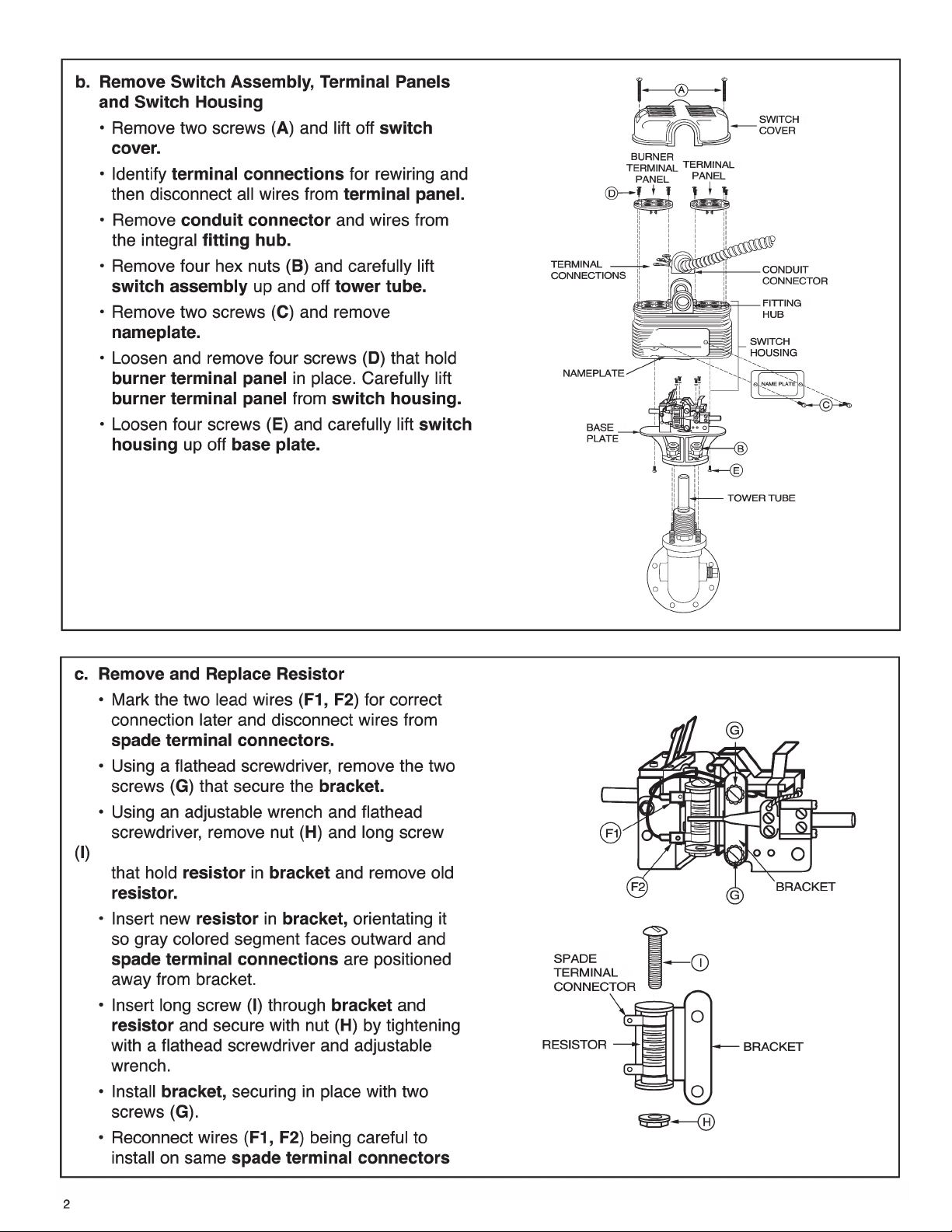
STEP 1 - Removal and Replacement of Contacts and Terminal Panels
a. Turn power off to boiler and all controls.
Allow boiler to cool to 80˚F (27˚C) and
reduce the pressure to 0 psi (0 bar).
ON
CAUTION
There may be more than one source of power to
the boiler.
OFF
Page 2
Page 3

Page 4

STEP 2 - Testing
!
!
– Dimensions shown are typical.
– The following testing procedure is only meant to serve as a verification of proper
operating sequence.
a. Turn on power to boiler and pump circuits.
With the boiler empty, the pump should turn on (5 or 5-M switch models) or the valve open
(7B or 7B-M switch models). The burner should remain off and boiler should begin to fill with water.
CAUTION
Immediately turn off all power if the burner turns on with no water in the gauge glass.
Investigate further before continuing procedure.
b. For Automatic Reset Models
When water level in the gauge glass is approximately 1 3/8” (35mm) above the horizontal cast line,
the burner should turn on.
For Manual Reset Models
When water level in the gauge glass is approximately 1 3/8” (35mm) above t
press the manual reset button and the burner should turn on.
c. For 5 or 5-M Switch Models
When water level in the gauge glass is approximately 2 1/8” (54mm) above the horizontal cast line,
the pump should turn off.
For 7B or 7B-M Switch Models
When water level in the gauge glass is approximately 2 11/16” (68mm) above the horizontal cast
line, the valve should be closed.
he horizontal cast line,
CAUTION
If pump does not turn off or valve close, turn off water supply to boiler.
Investigate further before continuing procedure.
d. With the water in the boiler at its normal level and burner on, SLOWLY open the blow-down v
alve
until it is fully open. As the water level in the gauge glass begins to drop, verify that the following
occurs.
For 5 or 5-M Switch Models
When water level drops to approximately 1 1/8” (29mm) above the horizontal cast line, the pump
should turn on.
When water level drops to the horizontal cast line, the burner should turn off.
For 7B or 7B-M Switch Models
As the water level drops, the valve should begin to open.
e t
When the water level drops to approximately 7/8” (22mm) abov
he horizontal cast line, the valve
should be full open.
When the water level drops to the horizontal cast line, the burner should turn off.
e. Close the blow-down valve after burner turns off and restore water level to normal operating level.
f. Repeat testing procedure several times to ensure proper operation of control.
g. After testing and verification of control operation, the boiler can be returned to service.
Xylem Inc.
8200 N. Austin Avenue
Morton Grove, Illinois 60053
Phone: (847) 966-3700
Fax: (847) 965-8379
www.xyleminc.com/brands/mcdonnellmiller
McDonnell & Miller is a trademark of Xylem Inc. or one of its subsidiaries.
© 2012 Xylem Inc. MM-709B August 2012 Part No. 210419
 Loading...