

Page 1
Replacement Switch Assembly
!
5 Burner/Pump Control
5-M Burner/Pump Control – Manual Reset
7B Proportional Control
7B-M Proportional Control – Manual Reset
For Series:
93 94
193 194
Pump Controller/Low Water Cut-Off
INSTRUCTION MANUAL
MM-706B
Replacement Switch
Electrical Ratings
Models with 5 and 5-M Switch
Pump and Burner Switch Contact Ratings
Voltage Pilot Duty Only
120 VAC
240 VAC
CAUTION
WARNING
345 VA
• Before using this product read and understand instructions.
• Save these instructions for future reference.
• All work must be performed by qualified personnel trained in the proper
application, installation, and maintenance of plumbing, steam, and electrical
equipment and/or systems in accordance with all applicable codes and ordinances.
• To prevent a fire, do not exceed the switch contact rating.
Models with 7B and 7B-M Switch
Switch Ratings
Burner Valve
120 VAC
345 VA 0 - 135 ohms @ 24 VAC
240 VAC
WARNING
Failure to follow this warning could cause property damage, personal injury or
death.
Page 2
O
FF
O
N
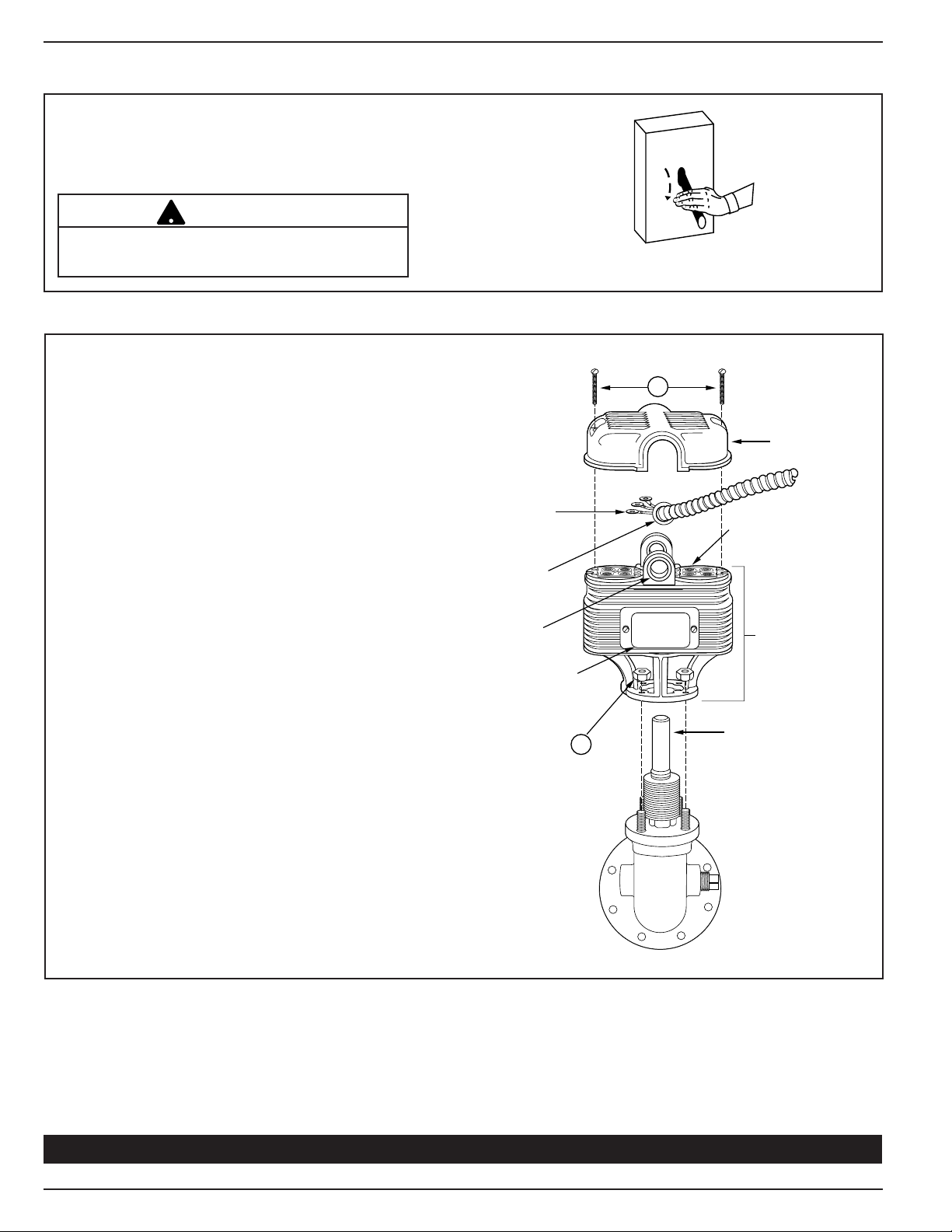
STEP 1 - Removal and Replacement of Contacts and Terminal Panels
T
O
W
E
R
T
UB
E
S
W
I
T
CH
A
S
S
E
MB
LY
TE
R
MI
N
A
L
C
ON
N
E
C
TI
ON
S
S
W
I
TC
H
C
OV
E
R
TER
MIN
AL
PAN
ELS
C
ON
D
U
I
T
C
ON
N
E
C
TOR
N
A
ME
P
LA
TE
FI
TTI
N
G
H
U
B
C
A
!
!
!
a. Turn power off to boiler and all controls.
Allow boiler to cool to 80˚F (27˚C) and
educe the pressure to 0 psi (0 bar).
r
CAUTION
There may be more than one source of power to
the boiler.
b. Remove and Replace Switch Assembly
• Remove two screws (A) and lift off
switch cover.
• Identify terminal connections for
rewiring and then disconnect all wires
from terminal panels.
• Remove conduit connector and wires
from the integral fitting hub.
• Remove four hex nuts (B) and carefully
lift switch assembly up and off
tower tube.
• Carefully slide new switch assembly
over tower tube and secure with four
hex nuts (B). Make sure nameplate is
in same position as old unit.
• Remove two screws (A) and lift switch
cover off new unit.
• Install conduit fitting from old unit
with attached wires on switch assembly.
• Reconnect wiring to terminal panel in
exactly the same position as removed.
• Replace switch cover and fasten with
two screws (A).
Proceed to Step 2 to Test Control
2
Page 3

STEP 2 - Testing
!
!
– Dimensions shown are typical.
– The following testing procedure is only meant to serve as a verification of proper
operating sequence.
a. Turn on power to boiler and pump circuits.
With the boiler empty, the pump should turn on (5 or 5-M switch models) or the valve open
(7B or 7B-M switch models). The burner should remain off and boiler should begin to fill with water.
CAUTION
Immediately turn off all power if the burner turns on with no water in the gauge glass.
nvestigate further before continuing procedure.
I
b. For Automatic Reset Models
When water level in the gauge glass is approximately 1 3/8” (35mm) above the horizontal cast line,
the burner should turn on.
For Manual Reset Models
When water level in the gauge glass is approximately 1 3/8” (35mm) above the horizontal cast line,
press the manual reset button and the burner should turn on.
c. For 5 or 5-M Switch Models
When water level in the gauge glass is approximately 2 1/8” (54mm) above the horizontal cast line,
the pump should turn off.
For 7B or 7B-M Switch Models
When water level in the gauge glass is approximately 2 11/16” (68mm) above the horizontal cast
line, the valve should be closed.
CAUTION
If pump does not turn off or valve close, turn off water supply to boiler. Investigate
further before continuing procedure.
d. With the water in the boiler at its normal level and burner on, SLOWLY open the blow-down valve
until it is fully open. As the water level in the gauge glass begins to drop, verify that the following
occurs.
For 5 or 5-M Switch Models
When water level drops to approximately 1 1/8” (29mm) above the horizontal cast line, the pump
should turn on.
When water level drops to the horizontal cast line, the burner should turn off.
For 7B or 7B-M Switch Models
As the water level drops, the valve should begin to open.
When the water level drops to approximately 7/8” (22mm) above the horizontal cast line, the valve
should be full open.
When the water level drops to the horizontal cast line, the burner should turn off.
e. Close the blow-down valve after burner turns off and restore water level to normal operating level.
f. Repeat testing procedure several times to ensure proper operation of control.
g. After testing and verification of control operation, the boiler can be returned to service.
3
Page 4

Xylem
1) The tissue in plants that brings water upward from the roots;
2) a leading global water technology company.
We’re 12,500 people unified in a common purpose: creating innovative solutions
to meet our world’s water needs. Developing new technologies that will improve
the way water is used, conserved, and re-used in the future is central to our work.
We move, treat, analyze, and return water to the environment, and we help people
use water efficiently, in their homes, buildings, factories and farms. In more than
150 countries, we have strong, long-standing relationships with customers who
know us for our powerful combination of leading product brands and applications
expertise, backed by a legacy of innovation.
For more information on how Xylem can help you, go to www.xyleminc.com
Xylem Inc.
8200 N. Austin Avenue
Morton Grove, Illinois 60053
Phone: (847) 966-3700
Fax: (847) 965-8379
www.xyleminc.com/brands/mcdonnellmiller
McDonnell & Miller is a trademark of Xylem Inc. or one of its subsidiaries.
© 2012 Xylem Inc. MM-706B November 2012 Part No. 210418
 Loading...