

Page 1
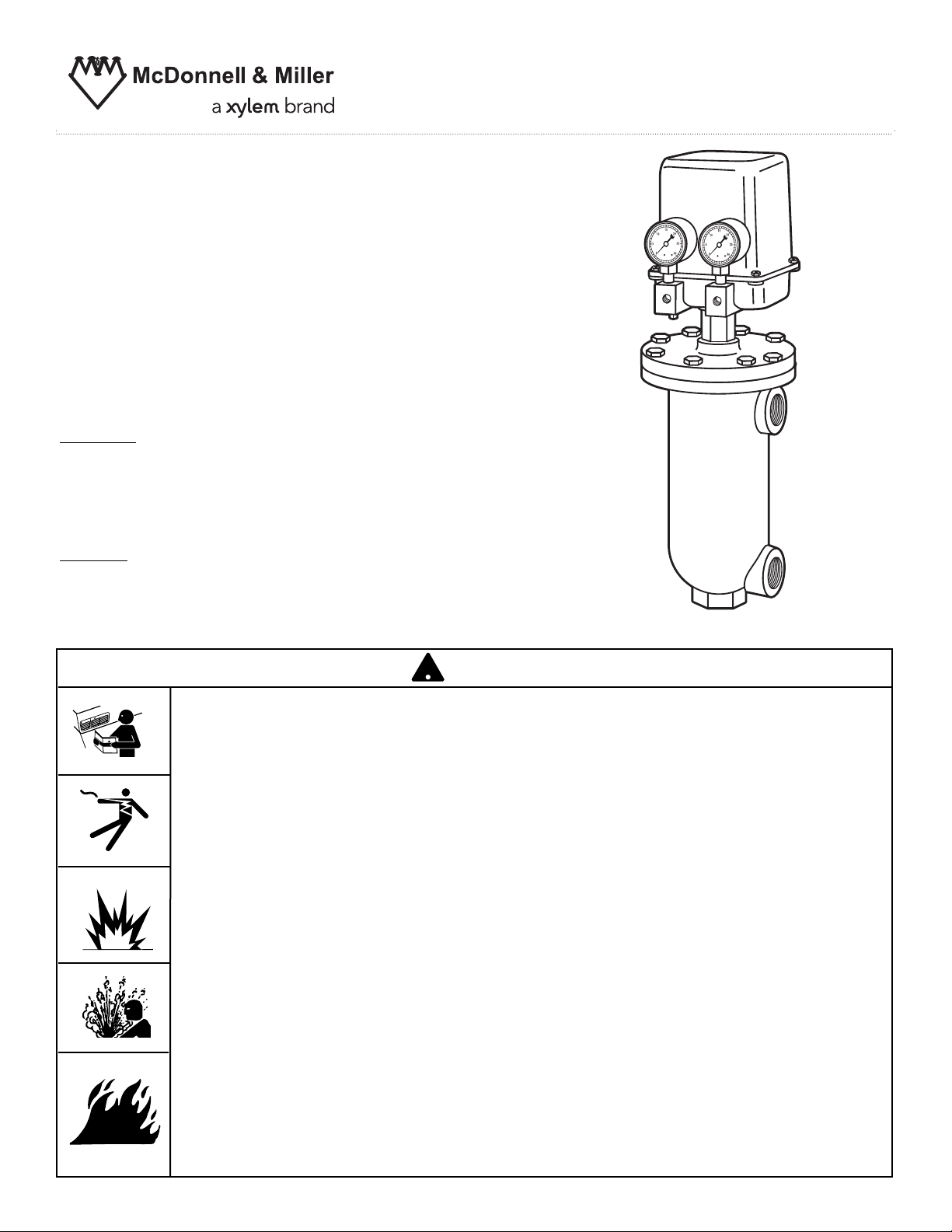
Model PFC-1-G (direct acting)
PFC-1-GR (reverse acting)
Modulating Pneumatic
Liquid Level Controls
APPLICATIONS:
– Use with other pneumatic devices, for liquid level
sensing in tank or pressure vessel where electrical
processes are not suitable, such as certain hazardous
locations.
Features:
– A float-operated, modulating, pneumatic level controller
– Side-mounting pipe connections
– Direct or reverse action convertible
– Field adjustable operating range & proportioning band
INSTRUCTION MANUAL
MM-110C
Ratings:
Maximum Vessel Pressure: 250 psig (17.6 kg/cm2)
Maximum Fluid Temperature: 406° F (208°C)
Maximum Supply Air Pressure: 20 psig (1.4 kg/cm
CAUTION
WARNING
• Before using product, read and understand instructions.
• Save these instructions for future reference.
• All work must be performed by qualified personnel trained in the proper application, installation,
and maintenance of plumbing, steam, and electrical equipment and/or systems in accordance
with all applicable codes and ordinances.
• If tank or receiver is pressurized relieve pressure to 0 psi (0 Bar) before servicing.
Drain water level down and let cool to 80°F (27°C).
• Boiler manufacturer schematics should always be followed. In the event that the boiler
manufacturer's schematic does not exist, or is not available from the boiler manufacturer,
refer to the schematics provided in this document.
• To prevent water damage check to make sure there is adequate floor drainage capacity.
Check all components in the system to insure they will not leak in the event of an
overfeed condition.
• After installation, check for proper operation of all of the limit and operating controls before
leaving the site.
California Proposition 65 warning! This product contains chemicals known to the
•
state of California to cause cancer and birth defects or other reproductive harm.
Previous controls should never be installed on a new system. Always install new
•
controls on a new boiler or system.
Failure to follow this warning could cause property damage, personal inj ury or death.
CAUTION:
•
A more frequent replacement interval may be necessary based on the condition of
the unit at time of inspection. McDonnell Miller s warranty is one (1) year from date
of installation or two (2) years from the date of manufacture.
2
WARNING
!
!
)
&
'
Page 2
2
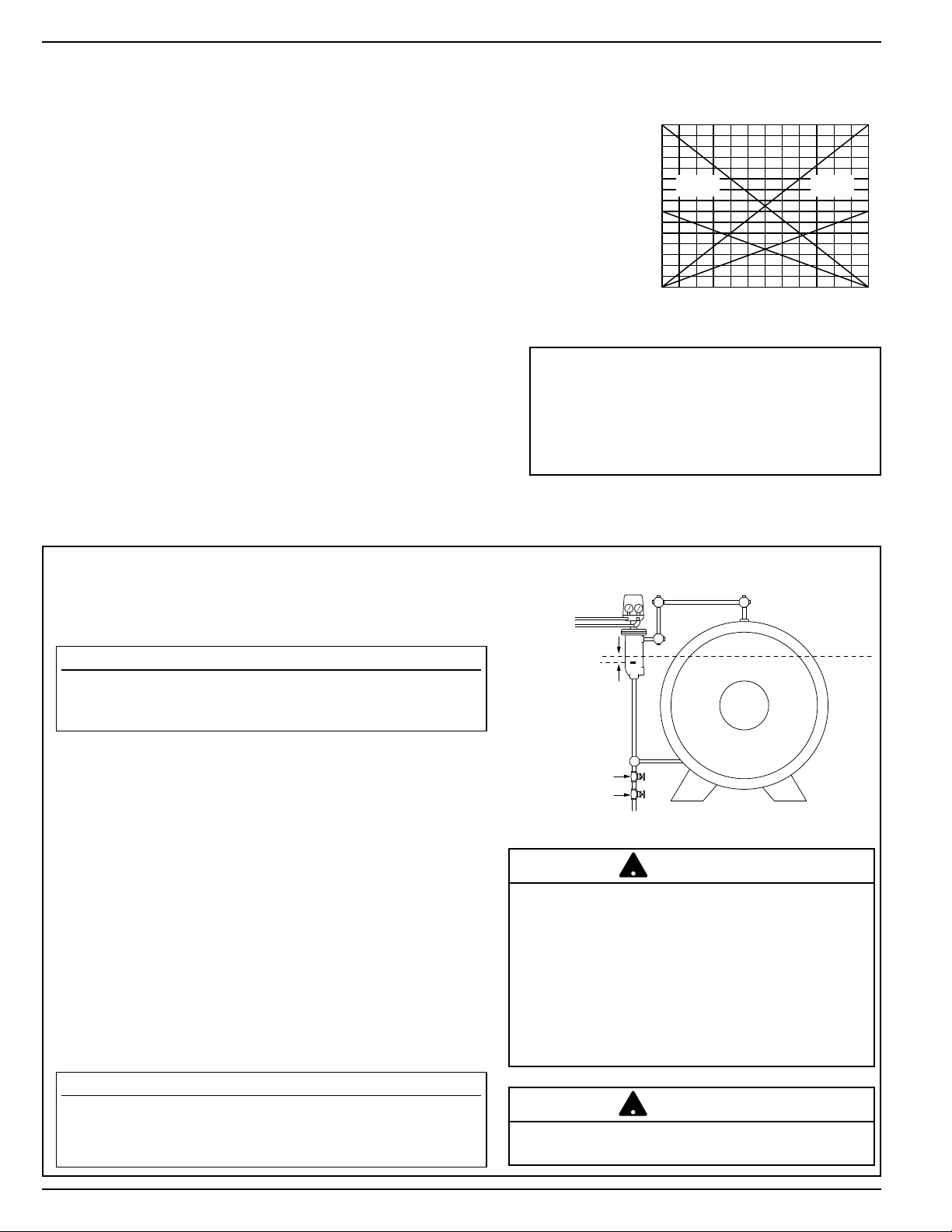
The model PFC should be installed vertically on the side
of the tank or vessel and connected with 1” equalizing
pipes. Plug all unused body connections. Control must be
plumb, with no more than a 2°-3° slant in any direction.
Control should be set with mark on casting 1” below the
desired operating level in tank. Keep equalizing lines as
short as possible and avoid creating any pockets. Crosses
with plugs should be used at any right angle connections
to facilitate cleaning. A blow-off valve should be installed
to permit blowdown operation and draining the float
chamber. All connections must be securely tightened in
leak-tight arrangement.
Gauges should be positioned for convenient reading.
Head assembly can be reoriented by removing 8 bolts in
the top of the head assembly and repositioning the entire
head as desired so gauges can be read conveniently.
Piping Hook-up
INSTALLATION –
Boiler / Hydronic Installation
TOOLS NEEDED:
Two (2) pipe wrenches, one (1) flathead screw driver
and pipe thread dope.
FACTORY SETTINGS
DIRECT ACTING—MODEL PFC-1-G - The higher the liquid
level, the higher the output pressure. Control can be changed
to Reverse Acting.
REVERSE ACTING—MODEL PFC-1-GR - The higher the liquid
level, the lower the output pressure. Control can also be changed
to Direct Acting.
NOTE: Pneumatic operated valves are also available as either
Direct Acting or Reverse Acting.When control and valve are the
same –both Direct Acting or Reverse Acting– the valve opens
as liquid level falls. When they are not the same, valve opens
as level rises.
MAXIMUM PROPORTIONAL BAND—Control goes through
its full operating range—from 3 to 15 psi output— with 2” of
level change inside the float chamber. The proportional band
can be adjusted to as little as 1” of level change.
SET POINT—The mark cast on float housing indicates the
low point of the control operating range. The operating level to
be maintained in the tank should be 1” above this mark. This
set point can be field adjusted about 3/4”.
OPERATION
The model PFC is float operated, and
mounts on the side of the tank or pressure
vessel. Its design allows field adjustment of
operational level, adjustment of proportional
band and conversion to either direct acting
or reverse acting operation.
Remove float blocking plug and dowel pin, located
in the bottom tapping of the control, before installation. Remove cardboard stop inside the top housing
before putting control in operation.
When using tape sealants on pipe or fittings external
threads follow the manufacturer's instructions—do
not place tape on first thread. When using thread
joint compound on pipe or fittings external threads
follow manufacturer's instructions—use sparingly
do not place compound on first thread.
!
CAUTION
Operating
Range
Proportional
Band
Output Air
2" (51mm)100%
1" (25mm)50%
3691215
(.2) (.4) (.6) (.8) (1)
Reverse
Acting
Direct
Acting
psi
(kg/cm
2
)
NOTE
The control is factory set to the mark on the float housing and
to maximum proportional band. If the proportional band is
adjusted, the point of minimum output may be as much as 1/2”
above the mark.
Be sure to release pressure from float chamber
before removing the 8 bolts.
!
CAUTION
IMPORTANT
Follow the boiler manufacturer’s instructions along with all
applicable codes and ordinances for piping, blow-down valve,
water gauge glass, tri-cock and electrical requirements.
OUTPUT AIR TO
CONTROL DEVICE
SUPPLY AIR
BALL VALVE
GATE VALVE
1”
DUAL
VALVE S
FOR
BLOW
DOWN
NORMAL
OPERATING
LEVEL
Page 3

3
TANK INSTALLATION
START-UP AND ADJUSTMENT PROCEDURE
AIR SUPPLY CONNECTIONS
It is good practice to install an air filter in the air supply
line. Control must be supplied with clean, dry instrument
air at 20 psi. (Supply pressure in excess of 20 psi will
cause a slight downward shift of the set point. Supply
pressure less than 20 psi may not give sufficient output pressure to achieve control valve close-off.)
Connect air supply to either of the two 1/8” NPT ports
directly below the gauge marked SUPPLY. Connect
either of the two ports below gauge marked OUTPUT
to valve or other control device. (Alternate ports are
provided for convenience; be sure to plug the two
ports not used with plugs provided.)
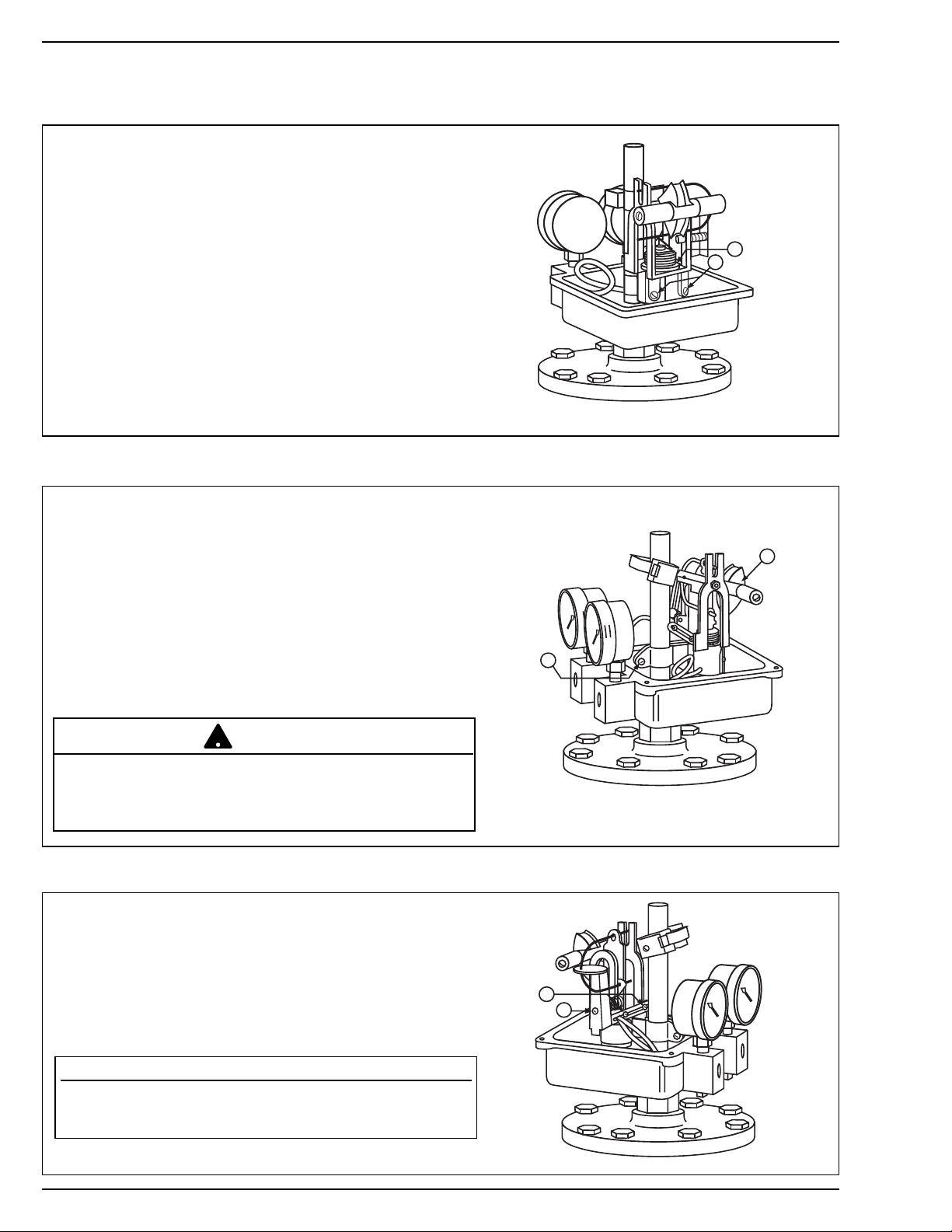
Remove cover from head of control. Carefully remove
cardboard shipping stop under the yoke, by straightening
the tabs on the sides and folding it lengthwise. Turn on
air supply.
Check the supply gauge for proper air pressure—20 psi
maximum. Gently swing the yoke through its full arc of
travel to make sure the magnets do not rub against the
tower tube (A).
Check the output gauge for proper output. Move the
yoke through its full arc; output should range from 3 to
15 psi. With the yoke in a horizontal position, the output should be approximately 9 psi.
To Start Operation (After all piping installation has been completed)
5” Min. Clearance Required
to Remove Cover
1/8” NPT
Output
OUTPUT AIR TO
CONTROL DEVICE
SUPPLY AIR
1”
1/8” NPT
Supply
NORMAL
OPERATING
LEVEL
7” O.D.
BALL VALVE
GATE VALVE
DUAL
VALVE S
FOR
BLOW
DOWN
A
Page 4
4
When the control is placed in service, and after any
adjustment, make sure of proper air output. With
cover removed, and air supply turned on, check that
the output gauge shows a range from 3 to 15 psi
when the yoke is moved manually through a full arc of
travel. With the yoke in horizontal position, the output
should be approximately 9 psi.
If necessary to adjust: Loosen the two relay lock
screws (C). Turn knurled adjusting collar (D) until output is 9 psi with yoke held in horizontal position.
(Rotate the collar clockwise, when viewed from the
top, to increase the output pressure or counter clockwise to decrease.) Tighten two lock screws securely.
To Adjust Air Output
For later reference, note proper orientation of control
mechanism with base. Slightly loosen clamp screw
(E), and slide control mechanism up or down on the
tower tube. If practical, adjust the level of the liquid to
desired control point, approximately 1” above the low
level mark on the float housing.
Make sure mechanism is in proper orientation with
base: the (M) yoke counterbalance weights should be
parallel to the back side of the base. Then tighten
clamp screw securely.
To Adjust Operating Level (Set Point)
START-UP AND ADJUSTMENT PROCEDURE (continued)
The position of the clamp screw must not be higher
than the top surface of the mechanism housing.
Positioning the mechanism too high may cause the magnets
to disengage, resulting in loss of output control.
!
CAUTION
Loosen two locking screws at bottom of the proportional
band spring bracket (F). Turn the proportional band
adjusting screw (G) until the desired proportional band
is attained. (Screw is full out for factory-set maximum
band.) Tighten two locking screws in spring bracket
securely.
To Adjust Proportional Band
NOTE
This adjustment may require several small incremental
changes followed by operational checks before final setting
is achieved.
D
C
M
E
F
G
Page 5

When the control is placed in service, and after any adjustment,
make sure that magnets clear the tower tube. With cover
removed, move the yoke manually through a full arc of travel.
If necessary to adjust: Loosen pivot screw lock nut (B), using a
11/32” wrench. Adjust pivot screw (not shown) in a direction to
free the rubbing. When magnets clear tube properly, tighten
lock nut securely, and make sure the yoke is engaged with
internal armature.
After installation, test the control for operating levels and reposition
the mechanism, if necessary. Make sure the magnets are
engaged with the internal armature. Engagement is indicated
by resisting movement. Replace cover.
5
Remove two locking screws at bottom of proportional band
spring bracket (F). Remove proportional band adjusting screw
and coil spring (G). Remove proportional band spring bracket
and U-shaped proportional band spring (H). It may be necessary
to compress U-shaped spring slightly to withdraw it from the
upper spring follower (J) and lower guide (K).
Loosen two inner pivots (L), using a 5/16” open end wrench
on the hex-shaped base of the pivots. Rotate counterweight
(M) 180° until it rests on the stop. The eccentric will display DA
when in the proper position for direct acting, and RA for reverse
acting operation.Tighten the two inner pivots (L) securely against
the yoke.
Swing spring follower (J) back to upright position. Carefully
replace proportional band spring bracket and U-shaped proportional band spring (H), making sure that top leg of spring passes
inside the spring follower and between the two upright arms,
and the bottom leg passes inside the guide (K).
Replace proportional band adjusting screw and coil spring (G).
Tighten adjusting screw until the lock screws (F) can be replaced
through the slots in the proportional band spring bracket.
Adjust proportional band as desired (see above) and tighten
lock screws (F).
To Change Direct Acting Operation to Reverse Acting Operation
START-UP AND ADJUSTMENT PROCEDURE (continued)
If Magnets Rub on Tower Tube
One of the pivots on the yoke arm is spring loaded; any lateral force
on the yoke may give a false picture of actual clearances.
!
CAUTION
Overtightening could loosen the eccentric from the lead
counterweight.
!
CAUTION
Perform the air output adjustment procedure after any other changes
to the mechanism.
!
IMPORTANT
M
H
F
G
L
J
K
B
Page 6

Troubleshooting
McDonnell & Miller
Shipment may cause the control to lose calibration. If
erratic operation is observed:
a. Check position of yoke movement relative to tube
tower magnet movement.
b. Position the clamp screw even with the rib of the
mechanism housing.
c. Perform ADJUST AIR OUTPUT procedure after
any changes to mechanism.
Too much vibration of the control or float or rapid level
changes may cause the magnets to disengage,
resulting in a loss of output control. Manually reengage the magnets by slowly moving the yoke
through its entire range of motion until the magnets reengage. If re-engagement does not occur, the float
and internal magnet assembly may be damaged.
Removal of the head from the chamber would then be
required to correct the condition.
MAINTENANCE
SCHEDULE:
• Blow down control weekly to verify operation.
When this control is used as a boiler control,
blow down control as follows when boiler is in
operation
-Daily if operating pressure is above 15 psi.
-Weekly if operating pressure is below 15 psi.
NOTE
More frequent blow-down may be necessary
due to dirty boiler water and/or local codes.
• Disassemble and inspect annually.
Replace the controller if it is worn, corroded,
or if components no longer operate properly.
• Inspect the float, chamber and equalizing piping
annually. Remove all sediment and debris.
• Replace control every 15 years.
More frequent replacement may be required when
severe conditions exist.
Internal (Wetted) Parts Dirty
The internal parts can operate improperly if dirt, scale
or rust is allowed to build. This condition can be a
result of not blowing down the control as recommended and/or improper boiler water chemical treatment.
Float is Crushed
Crushed floats are typically caused by improper blowdown. Drain piping from blow-down valve to drain
should be checked for proper pitch and the blow-down
procedure followed when blowing down the control.
Purchase and install a new float ball after investigating and correcting the problem.
Float is Filled with Water
The seam weld on the float can sometimes deteriorate. This can be caused by the type of chemical treatment used in the boiler. While this is a rare occurrence, the chemical treatment supplier should be consulted to determine if a reaction could occur.
Purchase and install a new float after investigating
and correcting the problem.
PROCEDURE
CAUTION
!
To prevent serious personal injury from steam pipe
blow down, connect a drain pipe to the control
opening to avoid exposure to steam discharge.
Failure to follow this caution could cause
personal injury
When blowing down a control at pressure, the blowdown valve should be opened slowly. The piping needs
to be warmed up and stagnant water in the drain piping
needs to be pushed out. Suddenly opening a blow-down
valve causes steam to condense, which creates water
hammer. Damage to components can occur when water
hammer occurs due to improper blow-down piping.
For these reasons, McDonnell & Miller recommends
a dual valve blow-down system for each control.
1. With water in the boiler at its normal level, open
“Positive Shut-off Ball Valve”.
2. Open “Throttling Gate Valve” slowly until drain piping heats up and then open fully. Observe that the
water level starts falling in the gauge glass.
3. Close “Throttling Gate Valve” after verifying that
controlled air valve opens fully.
If this does not happen, immediately close all
valves, turn off burner and correct the problem.
4. Close “Positive Shut-off Ball Valve”.
5. Observe that the water level returns to its normal
level before leaving site.
.
NOTE
Xylem Inc.
8200 N. Austin Avenue
Morton Grove, Illinois 60053
Phone: (847) 966-3700
Fax: (847) 965-8379
www.xyleminc.com/brands/mcdonnellmiller
McDonnell & Miller is a trademark of Xylem Inc. or one of its subsidiaries.
© 2013 Xylem Inc. MM-110C July 2013 Part No. 210552
 Loading...