

Page 1
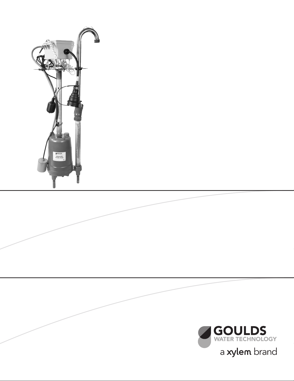
INSTRUCTION MANUAL
IM245
RGS2012E1
S or E Retrofit Kit
SUBMERSIBLE GRINDER PUMP
INSTALLATION, OPERATION AND TROUBLESHOOTING MANUAL
Page 2
SAFETY INSTRUCTIONS
DANGER
WARNING
CAUTION
CAUTION
TO AVOID SERIOUS OR FATAL PERSONAL INJURY
OR MAJOR PROPERTY DAMAGE, READ AND
FOLLOW ALL SAFETY INSTRUCTIONS IN MANUAL
AND ON EQUIPMENT.
THIS MANUAL IS INTENDED TO ASSIST IN THE
INSTALLATION AND OPERATION OF THIS UNIT
AND MUST BE KEPT WITH THE UNIT.
This is a SAFETY ALERT SYMBOL.
When you see this symbol on the
pump, the controller or in the
manual, look for one of the following signal words and be alert to
the potential for personal injury or
property damage.
Indicates an imminently hazardous
situation which, if not avoided, will
result in death or serious injury.
Indicates a potentially hazardous
situation which, if not avoided, could
result in death or serious injury.
Indicates a potentially hazardous
situation which, if not avoided, may
result in minor or moderate injury.
PUMP INSTALLATION
Grinder pumps should be installed in a basin that
is vented per the local plumbing code in your area.
The pump is not to be installed in locations that are
hazardous in accordance with the NEC. All plumbing
should be beneath the frost line for the region station
is installed in to ensure that pipes do not freeze.
Never lift the pump by the cord. Use
the lifting rope provided with the retro-
fit kit for lifting.
OLD PUMP REMOVAL
1. Supply power must be turned off
2. Goulds Water Technology recommendation is to
use a 20 amp circuit breaker. Check the existing
panel for breaker size and replace if necessary.
NOTE: INDICATES SPECIAL INSTRUCTIONS
WHICH ARE VERY IMPORTANT AND
MUST BE FOLLOWED.
THOROUGHLY REVIEW ALL INSTRUCTIONS
AND WARNINGS PRIOR TO PERFORMING ANY
WORK ON THIS CONTROLLER.
MAINTAIN ALL SAFETY DECALS.
ALL OPERATING INSTRUCTIONS MUST BE
READ, UNDERSTOOD, AND FOLLOWED BY THE
OPERATING PERSONNEL. GOULDS WATER
TECHNOLOGY ACCEPTS NO LIABILITY FOR
DAMAGES OR OPERATING DISORDERS WHICH
ARE THE RESULT OF NON-COMPLIANCE WITH
THE OPERATING INSTRUCTIONS.
1. This manual is intended to assist in the installation,
operation and repair of the system and must be
kept with the system.
2. Installation and maintenance MUST be performed
by properly trained and qualified personnel.
3. Review all instructions and warnings prior to performing any work on the system.
3. Remove the basin cover from the current station
4. If basin is full of water, pump water out with separate pump or vacuum truck. Discard waste in accordance with local, state and national codes.
5. Disconnect quick disconnect.
2
4. Any safety decals MUST be left on the pump.
5. The system MUST be disconnected from the main
power supply before attempting any operation or
maintenance on the electrical or mechanical part of
the system. Failure to disconnect electrical power
before attempting any operation or maintenance
can result in electrical shock, burns or death.
Page 3
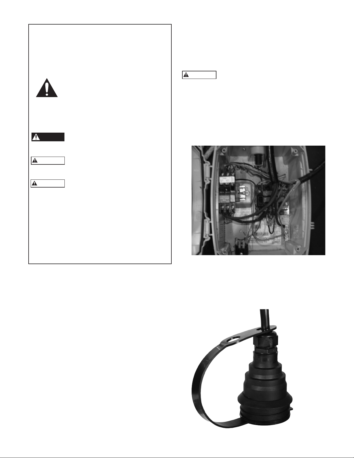
6. Check connections to make sure they are clean
WARNING
and dry.
7. Inspect connection, there are two styles round connectors- shown above and rectangular connectors.
Ensure that the correct Retrofit Kit has been purchased for the style connection being replaced.
8. Remove bolts from cover plate of current unit
3. Retighten all connections, check hardware, and
ensure that no wires or any other obstructions are
in way of pump cutters.
4. Make sure all fittings are tight.
5. Apply gasket tape to the bottom of the cover perimeter, poke holes through the tape at the cover
bolts entries.
9. Close valve of current unit
10. Secure rope to hooks on cover. Lift Unit from
basin.
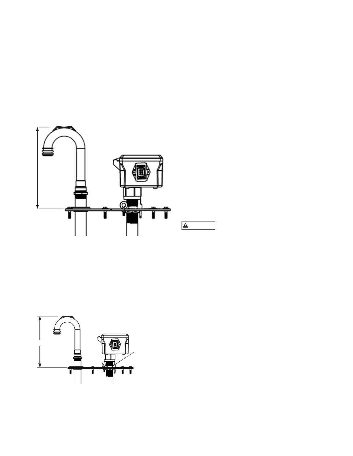
11. Measure distance on Candy cane for setting up
new retrofit – see below.
INSTALLING THE GOULDS WATER
TECHNOLOGY RETROFIT KIT
1. Adjust the center nut until the candy cane elbow
distance measured above matches the old unit.
(This is pre-set at factory to 12.38”.) Secure adjustable nuts with Loctite so that vibration does not
loosen the nut.
6. Lubricate O-rings on the discharge elbow to ease
installing into the receiver.
7. Using rope lower the grinder assembly in the basin. Align cover tabs to tank slots.
8. Align discharge elbow to Receiver. Unit will rest
on the tank flange with the elbow fully inserted in
receiver.
9. Open valve to latch with the discharge elbow.
Adjustment to nut may need to be made to alter
height at this point.
10. Once in place and latched install the 6 bolts back
into the cover plate.
11. Reconnect the power adapter from the power to
the new retrofit kit adapter.
12. Check electrical resistance to make sure that the
panel is free of shorts and ground faults.
13. Check grounding connections is made properly
Licensed electricians should be present
for panel or breaker energizing. If faults
caused by damage or poor installation have not
been detected, serious damage can result when
power is applied.
14. Turn on power to breakers.
15. Fill tank to test if pump and floats operate properly. See troubleshooting chart for problems
encountered.
16. Once tested and operating properly replace the
basin cover.
12.375
ADJUSTABLE NUTS
2. Check floats so that they have an unobstructed
free area in the tank. (These are pre-set at the
factory.)
18. Affix nameplate provided to the control panel so
the new unit can be identified as a RGS2012E1S or
E1E Retrofit Kit by Goulds Water Technology.
Pump specifics can be found under the standard
Goulds Water Technology product RGS2012 on the
website www.completewatersystems.com, Goulds
Water Technology Wastewater tab.
3
Page 4

TROUBLESHOOTING CHART
WARNING
Hazardous
voltage
FAILURE TO DISCONNECT AND LOCKOUT ELECTRICAL POWER BEFORE ATTEMPTING ANY
SERVICE CAN CAUSE SHOCK, BURNS OR DEATH.
SYMPTOM PROBABLE CAUSE RECOMMENDED ACTION
MOTOR NOT
RUNNING
NOTE: If circuit breaker
“OPENS” repeatedly,
DO NOT reset. Call
qualified electrician.
Motor thermal protector tripped. Allow motor to cool. Insure minimum pump
submergence. Clear debris from casing and
impeller.
Open circuit breaker or blown fuse. Determine cause, call a qualified electrician.
a) Manual operation Pump impeller binding or jammed.
Power cable is damaged.
Inadequate electrical connection in
control panel.
b) Automatic
operation
No neutral wire connected to control
panel.
Inadequate electrical connection in
control panel.
NOTE: Check the pump
in manual mode first
to confirm operation.
If pump operates, the
automatic control or
wiring is at fault. If pump
does not operate, see
above.
PUMP WILL NOT
Defective liquid level switch. With switch disconnected, check continuity
Insufficient liquid level to activate
controls.
Liquid level cords tangled. Untangle cords and insure free operation.
Liquid level cords tangled. Untangle cords and insure free operation.
TURN OFF
Pump is air locked. Shut off pump for approximately one minute,
Influent flow is matching pump’s
discharge capacity.
LITTLE OR NO
LIQUID DELIVERED
Check valve installed backwards,
plugged or stuck closed.
BY PUMP
Excessive system head. Consult with dealer.
Pump inlet plugged. Inspect and clear as required.
Improper voltage or wired incorrectly. Check pump rotation, voltage and wiring.
Pump is air locked. See recommended action, above.
Impeller is worn or damaged. Inspect impeller, replace as required.
Liquid level controls defective or
improperly positioned.
Check motor amp draw. If two or more times
higher than listed on pump nameplate,
impeller is locked, motor bearings or shaft
is damaged. Clear Inadequate electrical
connection debris from cutter, casing and
impeller, consult with dealer.
Resistance between power leads and ground
should read infinity. If any reading is incorrect,
call a qualified electrician.
Inspect control panel wiring. Call a qualified
electrician.
while activating liquid level switch. Replace
switch, as required.
Allow liquid level to rise 3” to 4” (76 mm - 101
mm) above turn-on level.
then restart. Repeat until air lock clears. If
air locking persists in a system with a check
valve, a 3⁄16” (4.8 mm) hole may be drilled in
the discharge pipe approximately 2” (51 mm)
above the discharge connection.
Larger pump may be required.
Check flow arrow on valve and check valve
operation.
Consult with qualified electrician.
Inspect, readjust or replace as required.
4
Page 5

TROUBLESHOOTING CHART
SYMPTOM PROBABLE CAUSE RECOMMENDED ACTION
PUMP CYCLES
CONSTANTLY
JUNCTION BOX WIRING DIAGRAM
Discharge check valve inoperative. Inspect, repair or replace as required.
Sewage containment area too small. Consult with dealer.
Liquid level controls defective or
improperly positioned.
Influent excessive for this size pump. Consult with dealer.
Inspect, readjust or replace as required.
123 45678
RED
ALARM
FLOAT
BLACK
ORANGE
PUMP ON/OFF
FLOAT
PUMP
WHITE
GREEN
N/C
5
Page 6
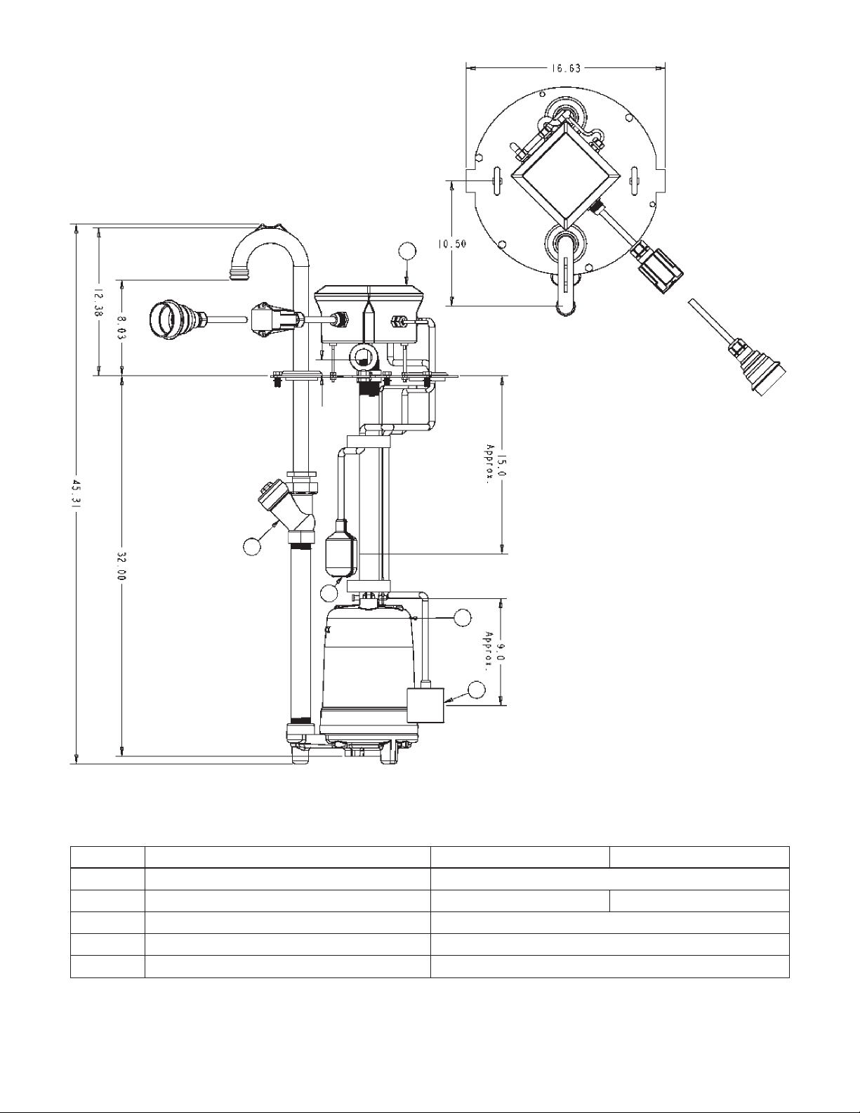
REPAIR PARTS
2
3
4
1
5
Item No. Major Components Standard Extreme
1 RGS2010 Grinder E1 RGS2012E1
2 Junction Box with Electrical Adaptor 9K600 9K601
3 Check / Anti-Siphon Valve A9-12BAS
4 Signal Master FS A2N03
5 Pump Master Plus FS A2E03
All dimensions ± 1/8 tolerance unless noted.
6
Page 7

NOTES
7
Page 8

GOULDS WATER TECHNOLOGY LIMITED WARRANTY
This warranty applies to all water systems pumps manufactured by Goulds Water Technology.
Any part or parts found to be defective within the warranty period shall be replaced at no charge to the dealer during the warranty period. The warranty period shall exist for
a period of twelve (12) months from date of installation or eighteen (18) months from date of manufacture, whichever period is shorter.
A dealer who believes that a warranty claim exists must contact the authorized Goulds Water Technology distributor from whom the pump was purchased and furnish complete details regarding the claim. The distributor is authorized to adjust any warranty claims utilizing the Goulds Water Technology Customer Service Department.
The warranty excludes:
(a) Labor, transportation and related costs incurred by the dealer;
(b) Reinstallation costs of repaired equipment;
(c) Reinstallation costs of replacement equipment;
(d) Consequential damages of any kind; and,
(e) Reimbursement for loss caused by interruption of service.
For purposes of this warranty, the following terms have these definitions:
(1) “Distributor” means any individual, partnership, corporation, association, or other legal relationship that stands between Goulds Water Technology and the dealer in
purchases, consignments or contracts for sale of the subject pumps.
(2) “Dealer” means any individual, partnership, corporation, association, or other legal relationship which engages in the business of selling or leasing pumps to customers.
(3) “Customer” means any entity who buys or leases the subject pumps from a dealer. The “customer” may mean an individual, partnership, corporation, limited liability
company, association or other legal entity which may engage in any type of business.
THIS WARRANTY EXTENDS TO THE DEALER ONLY.
Xylem, Inc.
2881 East Bayard Street Ext., Suite A
Seneca Falls, NY 13148
Phone: (888) 325-4210
Fax: (888) 322-5877
www.xyleminc.com/brands/gouldswatertechnology
Goulds is a registered trademark of Goulds Pumps, Inc. and is used under license.
© 2012 Xylem Inc. IM245 Rev. 0 June 2012
 Loading...