

Page 1
C
US
INSTRUCTION MANUAL
IM244R04
Models Covered:
SPD Plus
230V 1Ø Input 20-30 HP
230V 3Ø Input 40-60 HP
460V 40-100 HP
575V 40-100 HP
SPD Plus
VARIABLE SPEED PUMP CONTROL
INSTALLATION AND OPERATION MANUAL
U
L
®
Page 2
1
3. Strip wires.
3. Check the contents against the order
ground wires to the drive terminals.
See “Power Supply and Wiring”
in the instruction manual.
4. Connect power, motor and
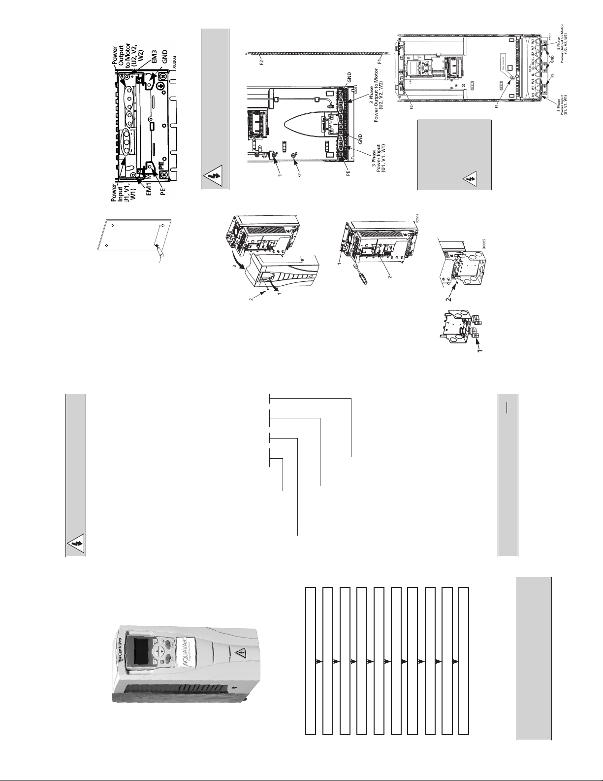
Frame Sizes R1…R4
and the shipping label to verify that all
parts have been received.
The drive requires a smooth,
vertical, solid surface, free from
heat and moisture, with free
Prepare the Mounting Location
WARNING! For oating networks
remove screws at EM1 and EM3 on
Frame Sizes R1…R4.
and PE for wiring.
* Single phase input power must use U1, W1
Frame Size R5
X0002
points.
1. Mark the mounting
2. Drill the mounting holes.
space for air ow – 200 mm (8
in.) above and below, and 25
mm (1 in.) around the sides of
the drive.
1. Remove the control panel
Remove the Front Cover
(display), if attached.
2. Loosen the
captive screw
at
the top.
top to remove
the cover.
3. Pull near the
SPD PLUS and use
1. Position the
screws or bolts to
securely tighten all
four corners.
Mount the Drive
Frame Size R6
WARNING!
sticker in the
appropriate lan-
guage on the inside
plastic shell.
2. Attach a warning
For oating net-
Install the Wiring (copper only)
F1 and F2
on Frame
works remove
screws at
Sizes R5 or R6.
supplied) in the conduit/gland box.
1. Install thin-wall conduit clamps (not
2. Install conduit/gland box.
1. Connect conduit runs to box.
Wiring Power
wiring through conduits.
2. Route input power and motor
_______________
___________________
______________________
_______________________
______________________________
WARNING! The Aquavar should ONLY
be installed by a qualied electrician.
Prepare for Installation
Check
frequency and voltage range must match drive
specifications (3 phase motor only).
• Motor Compatibility – Motor type, nominal current,
indoor controlled environment that is suitable for
• Suitable Environment – Drive requires heated,
the selected enclosure below 122º F (50º C).
requirements. Refer to NEC, Local, State or Munici-
pal codes.
Refer to the Installation Operation Manual and
• Wiring – Follow local codes for wiring and fusing
confirm that all preparations are complete.
Tools Required
Screwdrivers, wire stripper, tape measure, mount-
ing screws or bolts, and drill.
Use the following chart to interpret the type code
found on the drive label.
SPD 4 0600 N1
Single Pump Drive
Voltage
2 – 230 Volt 4 – 460 Volt 5 – 575 Volt
Task
Nominal Horsepower
0400 = 40 HP 0500 = 50 HP 0600 = 60 HP
0750 = 75 HP 1000 = 100 HP
Enclosure and Filter Options
Blank = NEMA 3R, no lter N1 = NEMA 1, no lter
F = NEMA 3R, with lter
NOTE: HP rating is for reference only, and is based on 3Ø input power.
• Voltage
• Nominal Motor Current
• Nominal Frequency
• Nominal Speed
Collect the following data from the motor nameplate
plate for later use in the Aquavar startup:
Collect Motor Data
• Nominal Power
NOTE: Lift the SPD PLUS by its chassis and not
by its cover.
Unpack the Drive
shipper immediately if damaged com-
ponents are found.
1. Unpack the drive.
2. Check for any damage and notify the
SPD PLUS
Quick Start Guide
The installation of the SPD PLUS adjust-able
Centrifugal Pump Controller
2
Overview
PREPARE for installation
UNPACK the drive
PREPARE mounting location
REMOVE the front cover
MOUNT the drive
INSTALL wiring
CHECK installation
REINSTALL the cover
APPLY power
speed drive follows the outline below.
START-UP Assistant
This guide provides a quick reference for
installing SPD PLUS drives having a standard
enclosure (NEMA 1).
NOTE: This guide does not provide detailed
installation, safety or operational instruc-
tions. See the Installation Operation Manual
for complete information.
Application
Page 3
1. Align the cover
Reinstall the Cover
and slide
3
it on.
5
11.1%
40.2 PSI sp
0.0 PSI ac
0.0 HZ
DIR MENU
LOC
REM
WARNING! The SPD PLUS will start
up automatically at power up, if the
external run command is on.
When power is applied to the SPD PLUS,
the captive
screw.
control panel.
2. Tighten
3. Reinstall the
Always reinstall the front cover before turn-
ing power on.
Apply Power
1
the green LED comes on.
1. Apply input power.
NOTE! Before increasing motor speed,
check that the motor is running in the
desired direction.
Run the Start-Up Assistant
to congure the motor and
Start-Up
REM
system parameters. If this is
the rst time the drive has
been powered, the display
will prompt the user if they
would like to run the Start-
Up Assistant. Select Yes to
run the Start-Up Assistant.
If this is not the rst time the drive has been
powered, follow the steps below:
1. From the Main Screen press MENU to
enter the MENU screen.
2. Select QUICKSTART
3. Select Start-Up
4. Follow the menu prompts to congure
the drive.
NOTE! For common parameters and
menu items, use the Help Key to
display descriptions. If you encounter
Alarms or Faults, use the Help Key or
refer to the Diagnostic section of the
instruction manual.
transducer
cable
1. Route the
Wiring the Transducer
through
the conduit.
2. Strip the
transducer
cable
sheathing
and twist
the screen
wire.
wire of the
transducer to
terminal X1-1.
transducer (red or brown) to terminal
X1-10.
transducer (white or black) to X1-5. See
chart in next column.
screw).
3. Connect the screen
4. Connect the power supply wire of the
5. Connect analog output wire from the
6. Install the conduit/gland box cover (1
Digital input impedance 1.5 kΩ. Maximum voltage
1
for digital inputs is 30 V.
Before applying power, perform the follow-
Check Installation
ing checks.
√ Check
Environment conforms to specifications.
The drive is mounted securely.
Proper cooling space around the drive.
Motor and driven equipment are ready for start.
Floating networks: Internal RFI filter disconnected.
Drive is properly grounded, with pump/motor.
Input power (mains) voltage matches the drive
nominal input voltage.
The input power (mains) terminals, U1, V1, W1,
are connected and tightened as specified.
The input power (mains) fuses / mains switch installed.
The motor terminals, U2, V2, W2, are connected
and tightened as specified.
Motor cable is routed away from other cables.
NO power factor compensation capacitors are
connected to the motor cable.
Control terminals are wired and tightened as specified.
NO tools or foreign objects (such as drill shavings) are
inside the drive.
NO alternate power source for the motor is connected
– no input voltage is applied to the output of the drive.
3
Page 4

INDEX
Important Safety Instructions................................................................................................................................................5
System Components .............................................................................................................................................................6
System Design ........................................................................................................................................................................ 8
Piping ....................................................................................................................................................................................10
Mounting the Controller .....................................................................................................................................................10
Power Supply and Wiring ...................................................................................................................................................11
Control Input and Output Functions .................................................................................................................................18
Starting the System ..............................................................................................................................................................19
Troubleshooting ...................................................................................................................................................................22
Appendix A - Input Power Requirements ........................................................................................................................27
Appendix B – Fuse and Wire Sizing ............................................................................................................................. 29-31
Appendix C - Weights and Dimensions ...........................................................................................................................31
Limited Warranty ..................................................................................................................................................................36
NOTE:
• Input and Output power connections require a minimum of 75ºC rated Copper wire only.
• In order to maintain the environmental rating integrity of the enclosure, all openings must be
closed by equipment rated Type 1 for Type 1 enclosures or Type 3R for Type 3R enclosures
• Maximum Ambient temperature range 5º F (-15º C) to 122º F (50º C).
• Maximum Humidity: 95% non-condensing.
4
Page 5

Hazardous
voltage
DANGER
Hazardous
voltage
DANGER
Hazardous
Pressure
CAUTION
SECTION 1: SAFETY INSTRUCTIONS
DANGER
WARNING
CAUTION
Hazardous
voltage
DANGER
Hazardous
voltage
DANGER
Hazardous
voltage
DANGER
Hazardous
voltage
DANGER
Hazardous
voltage
DANGER
Hazardous
voltage
DANGER
Hazardous
Pressure
CAUTION
TO AVOID SERIOUS OR FATAL PERSONAL INJURY
OR MAJOR PROPERTY DAMAGE, READ AND
FOLLOW ALL SAFETY INSTRUCTIONS IN MANUAL
AND ON EQUIPMENT.
THIS MANUAL IS INTENDED TO ASSIST IN THE
INSTALLATION AND OPERATION OF THIS UNIT
AND MUST BE KEPT WITH THE UNIT.
This is a SAFETY ALERT SYMBOL.
When you see this symbol on the
pump, the controller or in the
manual, look for one of the following signal words and be alert to
the potential for personal injury or
property damage. Obey all messages that follow this symbol to avoid
injury or death.
Indicates an imminently hazardous
situation which, if not avoided, will
result in death or serious injury.
Indicates a potentially hazardous
situation which, if not avoided, could
result in death or serious injury.
Indicates a potentially hazardous situation which, if not avoided, may result
in minor or moderate injury.
5. The system MUST be disconnected
from the main power supply before
attempting any operation or main-
tenance on the electrical or mechanical part of
the system. Failure to disconnect electrical power
before attempting any operation or maintenance
can result in electrical shock, burns or death.
6. When in operation, the motor and
pump could start unexpectedly and
cause serious injury.
7. Even when the motor is stopped,
dangerous voltage is present at the
Power Circuit terminals U1, V1, W1
and U2, V2, W2 and, depending on the frame size,
UDC+ and UDC-, or BRK+ and BRK-.
8. WARNING! Dangerous voltage is
present when input power is con-
nected. After disconnecting the supply, wait at least 5 minutes (to let the intermediate
circuit capacitors discharge) before removing the
cover.
9. WARNING! Even when power is
removed from the input terminals of
the SPD Plus, there may be dangerous voltage (from external sources) on the power
disconnect or terminals of the relay outputs R01…R03.
CAUTION
Used without a safety alert symbol
indicates a potentially hazardous
situation which, if not avoided, could
result in property damage.
NOTICE: INDICATES SPECIAL INSTRUCTIONS
WHICH ARE VERY IMPORTANT AND
MUST BE FOLLOWED.
THOROUGHLY REVIEW ALL
INSTRUCTIONS AND WARNINGS
PRIOR TO PERFORMING ANY
WORK ON THIS CONTROLLER.
MAINTAIN ALL SAFETY DECALS.
All operating instructions must be read,
understood, and followed by the operating
personnel. CentriPro accepts no liability for
damages or operating disorders which are the
result of non-compliance with the operating
instructions.
1. This manual is intended to assist in the installation,
operation and repair of the system and must be
kept with the system.
2. Installation and maintenance MUST be performed
by properly trained and qualied personnel.
3. Review all instructions and warnings prior to performing any work on the system.
4. Any safety decals MUST be left on the controller
and/or pump system.
10. WARNING! When the control termi-
nals of two or more drive units are
connected in parallel, the auxiliary
voltage for these control connections must be
taken from a single source which can either be
one of the units or an external supply.
11. WARNING! The SPD Plus is not a
eld repairable unit. Never attempt to
repair a malfunctioning unit; contact
the factory or your local Authorized Service Center
for replacement.
12. WARNING! The SPD Plus will start up
automatically after an input voltage
interruption if the external run command is on.
13. WARNING! The heat sink may reach a high
temperature, in excess of 200º F. Severe
burns are possible.
14. WARNING! If the drive will be used
in a oating network, remove screws
at EM1 and EM3 (Frame size R4) or F1
and F2 (Frame size R5 or R6).
NOTE! For more technical information, contact the
factory or your local SPD Plus representative.
15. WARNING! Always consult your lo-
cal, state, municipal or NEC codes for
proper wiring, electrical installation of
inverter drives and AC motors.
5
Page 6
SECTION 2: SYSTEM COMPONENTS
WARNING
Hazardous
voltage
Hazardous
Pressure
CAUTION
Please review the SPD Plus Variable Speed Pump Controller components and ensure that you have all the parts
and are familiar with their names. Be sure to inspect all components supplies for shipping damage.
SPD Plus Variable Speed Pump Controller Package:
• SPD Plus Variable Speed Controller
• Pressure Transducer with Cable
• Output Reactor (if ordered)
• Installation and Operation Manual
WARNING
DO NOT power the unit or run the pump until all electrical and plumbing connections,
especially the pressure sensor connection, are completed. The pump should not be run dry.
All electrical work must be performed by a qualied technician. Always follow the National
Electrical Code (NEC), or the Canadian Electrical Code (CEC) as well as all local, state and
provincial codes. Code questions should be directed to your local electrical inspector or code
enforcement agency. Failure to follow electrical codes and OSHA safety standards may result in
personal injury or equipment damage. Failure to follow manufacturer's installation instructions
may result in electrical shock, re hazard, personal injury, death, damage to equipment, unsatisfactory
performance and may void manufacturer's warranty.
SPD PLUS TYPE CODE AND PART NUMBER
Type Code:
SPD 4 0600 N1
Enclosure and Filter Options
Blank = NEMA 3R, no lter
F = NEMA 3R, with lter
N1 = NEMA 1, no lter
Nominal Horsepower
0400 = 40 HP
0500 = 50 HP
0600 = 60 HP
0750 = 75 HP
1000 = 100 HP
Voltage
2 = 230V
4 = 460V
5 = 575V
Single Pump Drive
NOTE: HP rating is for reference only, and is based on 3Ø input power.
6
Page 7

PART NUMBERS
Nominal HP Rating
Supply
Voltage
208/230
460
575
NOTES
1) Refer to Appendix C for frame size details.
2) Drive supplied with pressure transducer and manual.
3) Controllers with an N1 sufx have a NEMA 1 enclosure and are rated for indoor use only.
Model Number
SPD20400 40 20 103 51 114 57 N6
SPD20400F 40 20 129 64 143 72 N6
SPD20400N1 40 20 103 51 114 57 R4
SPD20500 50 25 129 64 143 72 N6
SPD20500F 50 25 160 80 178 89 N6
SPD20500N1 50 25 129 64 143 72 R6
SPD20600 60 30 160 80 178 89 N6
SPD20600F 60 30 199 99 221 111 N6
SPD20600N1 60 30 160 80 178 89 R6
SPD40400 40 — 53 — 59 — N4
SPD40400F 40 — 65 — 72 — N4
SPD40400N1 40 — 53 — 59 — R4
SPD40500 50 — 65 — 72 — N4
SPD40500F 50 — 87 — 97 — N5
SPD40500N1 50 — 65 — 72 — R4
SPD40600 60 — 87 — 97 — N5
SPD40600F 60 — 87 — 97 — N5
SPD40600N1 60 — 87 — 97 — R4
SPD40750 75 — 113 — 125 — N6
SPD40750F 75 — 113 — 125 — N6
SPD40750N1 75 — 113 — 125 — R5
SPD41000 100 — 141 — 157 — N6
SPD41000F 100 — 141 — 157 — N6
SPD41000N1 100 — 141 — 157 — R6
SPD50400N1 40 — 47 — 52 — R4
SPD50500N1 50 — 69 — 77 — R6
SPD50600N1 60 — 69 — 77 — R6
SPD50750N1 75 — 89 — 99 — R6
SPD51000N1 100 — 130 — 144 — R6
3 Phase
Input
1 Phase
Input
Full Load Output
Current (50C)
3 Phase
Input
1 Phase
Input
Full Load Output
Current (40C)
3 Phase
Input
1 Phase
Input
Frame
Size
7
Page 8

SECTION 3: SYSTEM DESIGN
SPD PLUS CENTRIFUGAL PUMP CONTROL SYSTEM
The SPD Plus pump controller is a simple, easy to use
and commission Variable Speed Drive (VSD) designed
specically for use in submersible or above ground
pump systems. The SPD Plus features an integrated
Start-Up Assistant which simplies system commissioning and setup.
NOTE
The SPD Plus is not recommended for the residential
well applications. Consult CentriPro for suitable
Variable Speed Controllers designed for residential
well pumps.
The following diagrams show some typical system
designs using the SPD Plus.
NOTE
Systems MUST be designed by qualied technicians
only and meet all applicable state and local code
requirements.
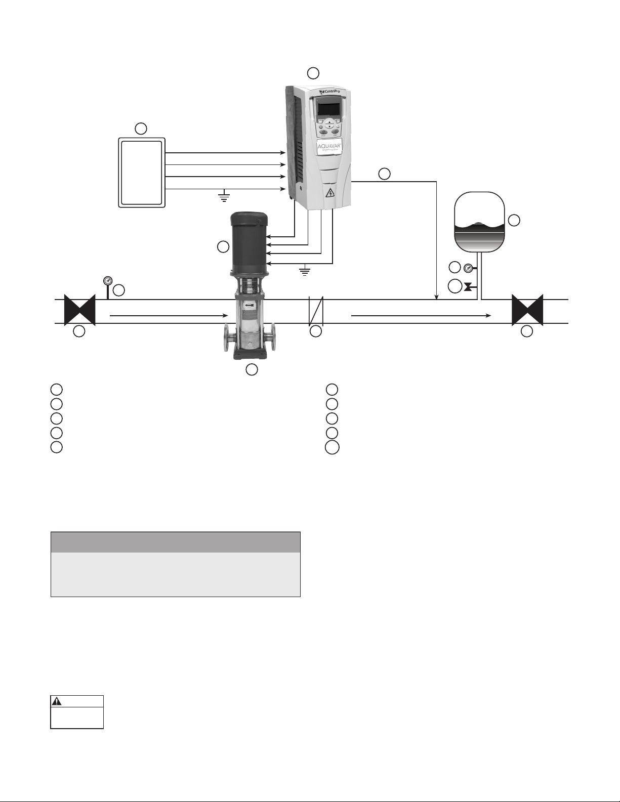
DIAGRAM #1 shows a typical set up for a submersible pump and control system.
1
2
SUPPLY POWER
U1
V1
W1
GND
6
U2
V2
W2
GND
8
1 DRIVE CONTROLLER
2 FUSIBLE DISCONNECT
3 PRESSURE GAUGE
4 AIR DIAPHRAGM TANK
5 PRESSURE TRANSDUCER
6 3 PHASE OUTPUT (ALWAYS)
7 DISCHARGE CHECK VALVE
8 GATE VALVE (HIGHLY RECOMMENDED
9 SUBMERSIBLE PUMP END
10 SUBMERSIBLE MOTOR (3 PHASE)
11 PRESSURE RELIEF VALVE
3
4
5
7
FLOW
11
9
10
8
Page 9
SECTION 3: SYSTEM DESIGN
1
Hazardous
Pressure
CAUTION
DIAGRAM #2 shows a set-up for an Above Ground booster pump and control system.
2
9
SUCTION
8
SUPPLY POWER
U1
V1
W1
GND
7
U2
V2
W2
3 PHASE OUTPUT
GND
TO MOTOR
4
5
9
10
FLOW
3
1 SPD CONTROLLER 6 AIR DIAPHRAGM TANK
2 FUSIBLE DISCONNECT 7 3 PHASE MOTOR
3 CENTRIFUGAL PUMP 8 GATE VALVE (BALL VALVE)
4 CHECK VALVE 9 PRESSURE GAUGE
5 PRESSURE TRANSDUCER (CABLE ASSEMBLY) 10 PRESSURE RELIEF VALVE
AIR
6
8
SECTION 4: PIPING
GENERAL
NOTE
All plumbing work must be performed by a qualied
technician. Always follow all local, state and provincial
codes.
A proper installation requires a pressure relief valve,
a ¼" female N.P.T. threaded tting for the pressure
sensor, and properly sized pipe. Piping should be
no smaller than the pump discharge and/or suction
connections. Piping should be kept as short as
possible. Avoid the use of unnecessary ttings to
minimize friction losses.
Some pump and motor combinations
controlled by the SPD Plus can create
dangerous pressure. Select pipe
and ttings according to your pipe suppliers’
recommendation. Consult local codes for piping
requirements in your area.
All joints must be airtight. Use PTFE thread seal tape
or another type of pipe sealant to seal threaded
connections. Please be careful when using thread
sealant as any excess that gets inside the pipe may
plug the pressure sensor.
Galvanized ttings or pipe should never be connected
directly to the stainless steel pump discharge or
casing as galvanic corrosion may occur. Barb type
connectors should always be double clamped.
PRESSURE TANK, PRESSURE RELIEF VALVE AND
DISCHARGE PIPING
Use only “pre-charged” tanks on this system. Do not
use galvanized tanks. Select an area that is always
above 34º F (1.1º C) in which to install the tank,
pressure sensor and pressure relief valve. If this is
an area where a water leak or pressure relief valve
blow-off may damage property, connect a drain line
to the pressure relief valve. Run the drain line from the
pressure relief valve to a suitable drain or to an area
where water will not damage property.
9
Page 10

SECTION 4: PIPING (CONTINUED)
Hazardous
Pressure
CAUTION
WARNING
Hazardous
voltage
PRESSURE TANK, SYSTEM PRESSURE
Sizing – A bladder tank (not included) is used to
cushion the pressure system during start-up and shut-
down. It should be sized to at least 20% of the total
capacity of your pump. Example: If your pump is sized
for 100 GPM then size your tank for at least 20 gal.
total volume, not draw down. Pre-charge your bladder
tank to 15-20 PSI below your system pressure. Use the
higher tank pre-charge setting if the system drifts over
5 PSI at a constant ow rate. NOTE: Pre-charge your
tank before lling with water!
CAUTION
Maximum working pressure of HydroPro
bladder tank is 125 psi.
INSTALLING THE PRESSURE SENSOR
The pressure sensor requires a ¼" NPT tting for
installation. Install the pressure sensor with the
electrical connector pointing up to avoid clogging the
pressure port with debris. Install the pressure sensor in
a straight run of pipe away from elbows or turbulence.
For optimum pressure control install the pressure
sensor in the same straight run of pipe as the pressure
tank. Ensure the pressure sensor is within 10 feet of
the pressure tank. Installing the pressure sensor far
away from the pressure tank may result in pressure
oscillations. Do not install the pressure sensor in a
location where freezing can occur. A frozen pipe
can cause damage to the pressure sensor.
The pressure sensor cable must be wired to the
controller control terminals. The pressure sensor
cable wiring diagram is shown in Section 6. The cable
can be shortened for a cleaner installation. Longer
cable lengths are available, consult factory. Maximum
recommended pressure sensor cable length is 300
feet. Avoid leaving a coil of pressure sensor cable as
this can induce unwanted transient voltages and noise
into the system. Do not run the pressure sensor cable
alongside the input or output wiring for more than 1
foot. Maintain a distance of at least 8” between the
pressure sensor cable and input or output wiring.
Ensure the pressure sensor cable is connected as
follows: Brown to terminal 10 (24VDC SUPPLY), White
to terminal 5 (AI2, TRANSDUCER FEEDBACK), Drain to
SCR Terminal 1. Connecting the Drain wire to the SCR
Terminal electrically connects the sensor case to the
chassis of the controller. In some cases this drain wire
must be disconnected from the controller chassis. In
cases where there is grounded metal piping which is
continuous between the transducer and the motor or
the transducer is installed in grounded metal piping,
a ground loop can result so the drain wire must be
disconnected from the chassis. In cases where there
are sections of nonmetallic piping between the
transducer and motor or the transducer is installed
in ungrounded piping this drain wire should be
connected to the controller chassis.
SECTION 5: MOUNTING THE
CONTROLLER
GENERAL
Mount the controller in a ventilated, shaded area.
The controller must be mounted vertically. Be sure
to leave 8 inches of free air space on every side of
the unit. The controller must be in an area with an
ambient between 5 ºF (-15 ºC) and 122 ºF (50 ºC).
If installation is above 3300 feet above sea level,
ambient temperatures are derated 1% per 330 feet
above 3300 feet. The altitude limit for this controller is
6600 ft. Do not install above 6600 ft.
NOTE
Do not block the heat sink (ns) and fans and do not
set anything on the units.
WARNING
The controller access cover should
always be securely fastened to the control box due to the dangerous voltage/
shock hazard inside the unit.
NOTE
Controllers with an N1 sufx have a NEMA 1 enclosure and are rated for indoor use only.
10
Page 11
SECTION 6: POWER SUPPLY AND WIRING
WARNING
Hazardous
voltage
POWER CONNECTION DIAGRAMS
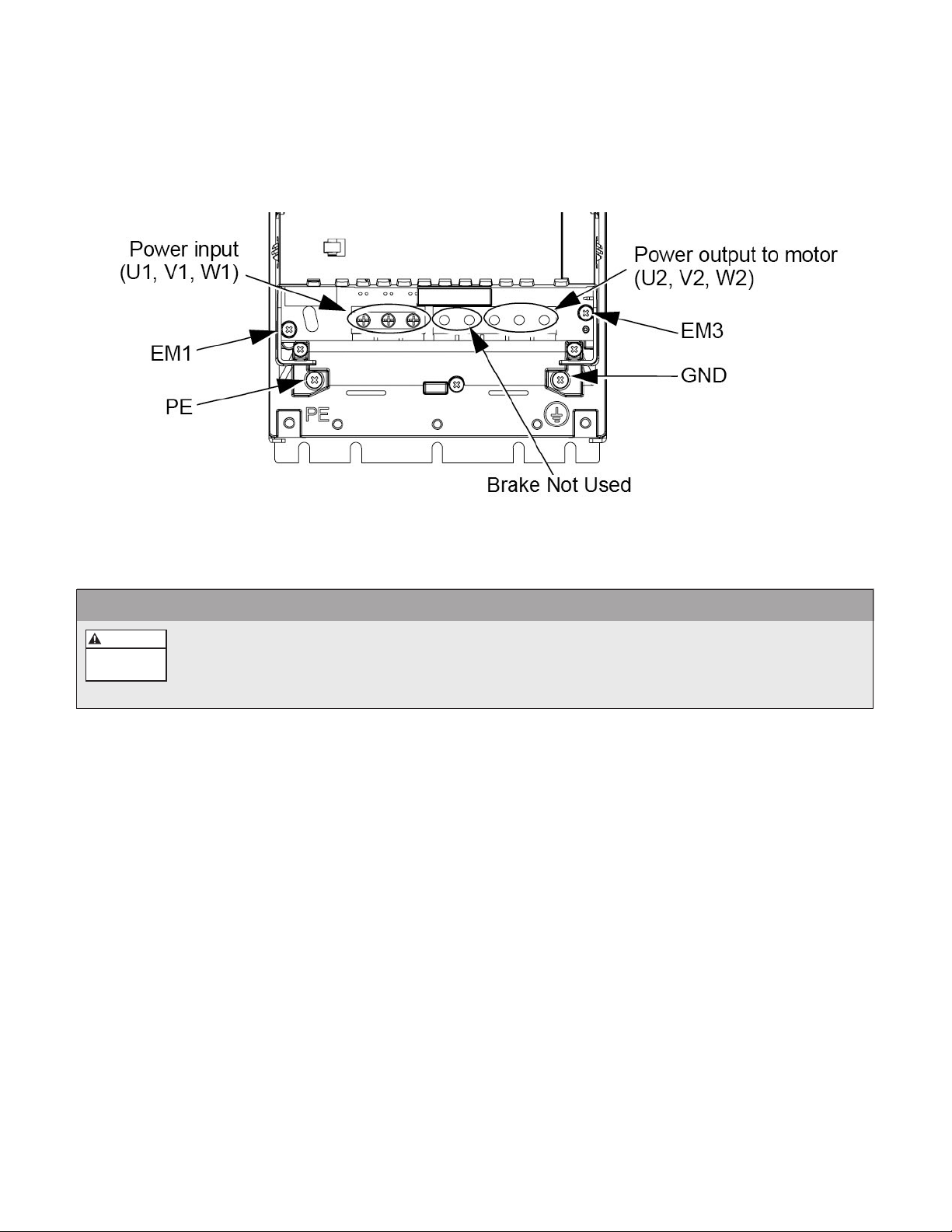
The following diagrams show the power connection layout for each frame size.
• For sizes R4 and N4
WARNING
If the secondary of the transformer is a delta with a grounded leg (corner grounded delta) or
oating network, the line to ground EMC lter components and line to ground MOV protection
must be disconnected or damage to the controller can result. Remove screws EM1 and EM3 for
frame sizes R4/N4 to disable line to ground EMC lter and MOV protection.
FIGURE 1
11
Page 12

SECTION 6: POWER SUPPLY AND WIRING (CONTINUED)
WARNING
Hazardous
voltage
POWER CONNECTION DIAGRAMS
The following diagrams show the power connection layout for each frame size.
• For sizes R5 and N5 • For sizes R6 and N6
FIGURE 2
FIGURE 3
WARNING
If the secondary of the transformer is a delta with a grounded leg (corner grounded delta) or
oating network, the line to ground EMC lter components and line to ground MOV protection
must be disconnected or damage to the controller can result. Remove screws F1 and F2 for
frame sizes R5/N5 and R6/N6 to disable line to ground EMC lter and MOV protection.
NOTE
For single phase input power, use input power terminals U1, W1 and PE (ground).
12
Page 13

SECTION 6: POWER SUPPLY AND WIRING (CONTINUED)
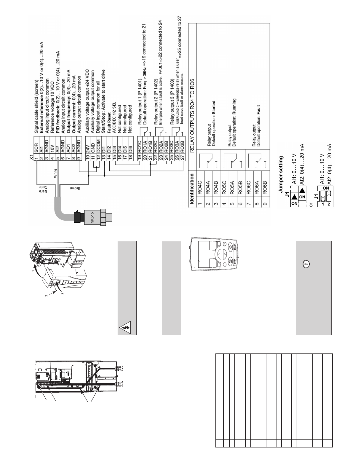
CONTROL TERMINAL CONNECTION DIAGRAM
The diagram below describes the control terminal connections.
NOTE
Pressure sensor cable must be wired during installation. All other connections are wired at the factory.
Identication RELAY OUTPUTS R04 TO R06
1 RO4C
2 RO4A
3 RO4B
4 RO5C
5 RO5A
6 RO5B
7 RO6C
8 RO6A
9 RO6B
NOTE
A jumper wire is installed between DI1 and +24V at the factory. To remotely start and stop the drive while in
REM mode, replace the jumper wire with a non-powered switch.
Relay output
Default operation: Started
Relay output
Default operation: Running
Relay output
Default operation: Fault
FIGURE 4
13
Page 14

WARNING
Hazardous
voltage
WARNING
Hazardous
voltage
SECTION 6: POWER SUPPLY AND WIRING
(CONTINUED)
INPUT POWER AND LINE TRANSFORMER
REQUIREMENTS
NOTE
Installation and maintenance MUST be performed
by properly trained and qualied personnel.
Always follow the National Electrical Code (NEC) or
Canadian Electric Code (CEC), as well as all state,
local and provincial codes when wiring the system.
The type of transformer and the connection
conguration feeding a drive plays an important
role in its performance and safety. The following is
a brief description of some of the more common
congurations and a discussion of their virtues and
shortcomings. Always ask what type of power system
the site has before sizing the drive.
DELTA/WYE WITH GROUNDED WYE NEUTRAL:
This conguration is one of if not the most common.
It provides rebalancing of unbalanced voltage with
a 30 degree phase shift. Depending on the output
connections from the drive to motor, the grounded
neutral may be a path for common mode current
caused by the drive output.
DELTA/DELTA WITH GROUNDED LEG
UNGROUNDED SECONDARY
Grounding of the transformer secondary is essential
to the safety of personnel as well as the safe operation
of the drive. Leaving the secondary oating can
permit dangerously high voltages between the
chassis of the drive and the internal power structure
components. In many cases this voltage could exceed
the rating of the input MOV protection devices of
the drive causing a catastrophic failure. In all cases,
the input power to the drive should be referenced to
ground. If the transformer can not be grounded, then
an isolation transformer must be installed with the
secondary of the transformer grounded.
WARNING
If the secondary of the transformer is
a delta with a grounded leg (corner
grounded delta) or oating network,
the line to ground EMC lter components and line
to ground MOV protection must be disconnected or
damage to the controller can result. Remove screws
EM1 and EM3 for frame sizes R4/N4 or F1 and F2
for frame sizes R5/N5 and R6/N6 to disable line to
ground EMC lter and MOV protection. Refer to
Figures 1, 2 and 3 for screw locations.
RESISTANCE GROUNDING AND GROUND FAULT
PROTECTION
Another common conguration providing voltage
rebalancing with no phase shift between input and
output. Again, depending on the output connections
from the drive to motor, the grounded neutral may be
a path for common mode current caused by the drive
output.
WARNING
If the secondary of the transformer is
a delta with a grounded leg (corner
grounded delta) or oating network,
the line to ground EMC lter components and line
to ground MOV protection must be disconnected or
damage to the controller can result. Remove screws
EM1 and EM3 for frame sizes R4/N4 or F1 and F2
for frame sizes R5/N5 and R6/N6 to disable line to
ground EMC lter and MOV protection. Refer to
Figures 1, 2 and 3 for screw locations.
14
Connecting the Wye secondary neutral to ground
through a resistor is an acceptable method of
grounding. Under a short circuit secondary condition,
any of the output phases to ground will not exceed
the normal line to line voltage. This is within the rating
of the MOV input protection devices on the drive.
The resistor is often used to detect ground current
by monitoring the associated voltage drop. Since
high frequency ground current can ow through this
resistor, care should be taken to properly connect the
drive motor leads using the recommended cables
and methods. In some cases, multiple drives on one
transformer can produce a cumulative ground current
that can trigger the ground fault interrupt circuit.
Page 15

WARNING
Hazardous
voltage
WARNING
Hazardous
voltage
OPEN DELTA (CONSULT FACTORY)
This type of conguration is common on 230 volt
systems. From time to time it may be encountered
where only single phase power is available and
three-phase power is required. The technique uses
two single phase transformers to derive a third phase.
When used to power a drive this conguration must
be derated to about 70% of the single phase rating of
one transformer. This system provides poor regulation
and it is possible that only the two line connected
phases will provide power. In this case the drive must
be derated to 50 % of its rating. (Ex. A 20 HP 230 volt
drive now becomes a 10 HP 230 volt drive.)
WARNING
“Open Delta” power systems should
be sized using the 50% derate factor.
Consult factory.
SINGLE PHASE CONNECTION
For drives with a diode rectier front end it is possible
to run a three phase output with a single phase input.
Only part of the three phase input bridge is used.
Ripple current becomes 120 Hz rather than 360. This
places a greater demand on the DC lter components
(capacitor bank and DC choke). The result is that the
drive must be derated to 50% current. Single phase
will not work with an SCR front end drive.
LINE TRANSFORMER
The line input voltage and transformer power must
meet certain phase and balance requirements. If
you or your installing electrical contractor is in
doubt of the requirements, the following provide
guidelines for the SPD Plus installation. When in
doubt contact the local power utility or the factory.
If an isolation transformer is used, the best choice is
ONE three phase, six winding transformer. A delta
primary is best for third harmonic cancellation. A wye
secondary avoids circulating current problems and
provides the very desirable option of grounding the
secondary neutral for minimum voltage stress and
ripple to ground. The transformer should have a KVA
rating at least 1.1 times the maximum connected HP.
A K factor of 6 is sufcient if transformer impedance
is greater than 2%. A K Factor of 5 is sufcient if
transformer impedance is greater than 3%. The
transformer manufacturer may provide derating for
non K Factor rated transformers to operate at the
drive produced K Factor levels.
Other transformer congurations are acceptable.
Three single phase transformers can be used if
they are identical for phase to phase symmetry and
balance. A wye connected primary neutral should
never be grounded. Great care should be taken with
delta primary delta secondary congurations. Any lack
of phase to phase symmetry could result in circulating
currents and unacceptable transformer heating.
WARNING
Never use phase converters with drives
as nuisance tripping and possible
damage may occur. Instead, use single
phase input power and 50% derate factor.
INPUT POWER SPECIFICATIONS
InputPower(mains)ConnectionSpecications
208/220/230/240 VAC 3-phase or 1-phase – 15% …+10% for SPD2XXXX
Voltage (U1) 380/400/415/440/460/480 VAC 3-phase -15%...+10% for SPD4XXXX
500/525/575/600 VAC 3-phase -15%....+10% for SPD5XXXX
Prospective Short- Maximum allowed prospective short-circuit current in the supply is 100 kA
Circuit Current providing that the input power cable of the drive is protected with
(IEC 629) appropriate fuses. US: 100 000 AIC.
Frequency 48…63 Hz
Imbalance Maximum ±3% of nominal phase to phase input voltage
Fundamental Power
0.98 (at nominal load)
Factor (cos phi1)
15
Page 16

SECTION 6: POWER SUPPLY AND WIRING
Hazardous
voltage
DANGER
(CONTINUED)
CONDUIT, WIRE AND FUSE SIZING
When selecting the input power cable follow the rules
below:
• Do not use aluminum wires
• The cable must be able to carry the drive load
current
• The cable must be rated for at least 75ºC
• A four conductor cable (three phases and ground)
or four insulated conductors routed through
conduit may be used. Shielding is not required.
The use of metal conduit with metal conduit
connectors is recommended for all electrical
connections. Use the NEC or CEC to determine
the required conduit size for the application.
Refer to the wire sizing tables in Appendix B to
determine the maximum length for the input and
output cables. The maximum recommended total
voltage drop on both input and output cable
combined is 5%. Standard wire sizing table provides
maximum cable lengths for input or output cables.
Because of this the lengths given in the table must be
adjusted so the total voltage drop does not exceed
5%. For example, if the input wire sizing chart in the
appendix gives the maximum length of 400' and
only 100' is used then only 25% of the total voltage
drop (1.25% drop) is used. The maximum output
cable length must then be adjusted to 75% of its
value so that the maximum voltage drop of 5% is not
exceeded.
Provide a dedicated fused disconnect rated for drives
input current rating. (Fused disconnect included for
NEMA3R enclosures.) No other equipment should be
used for this disconnect. Use fast acting class T fuses.
The recommended fuse sizes for each model are
listed below.
INPUT POWER CONNECTIONS
Before making this connection, measure and verify
the site voltage phase to phase and phase to ground.
In the case of high line to ground voltage it may be
necessary to disconnect the line to ground EMC and
MOV protection. See Figures 1, 2 and 3 for details.
Ensure the ground wire is connected back to the
service entrance ground and that the service entrance
ground is bonded to a proper ground rod.
Input
Voltage
230V
460V
575V
16
Model Number
SPD20400 114 150
SPD20400F 143 200
SPD20400N1 114 150
SPD20500 143 200
SPD20500F 178 250
SPD20500N1 143 200
SPD20600 178 250
SPD20600F 221 300
SPD20600N1 178 250
SPD40400 59 80
SPD40400F 72 90
SPD40400N1 59 80
SPD40500 72 90
SPD40500F 96 125
SPD40500N1 72 90
SPD40600 96 125
SPD40600F 96 125
SPD40600N1 96 125
SPD40750 124 175
SPD40750F 124 175
SPD40750N1 124 175
SPD41000 157 200
SPD41000F 157 200
SPD41000N1 157 200
SPD50400N1 52 60
SPD50500N1 77 100
SPD50600N1 77 100
SPD50750N1 99 150
SPD51000N1 144 200
Input Current
(Arms)
Mains Fuse Size
(UL Class T)
Ensure disconnect switches
are locked in the OFF
position before making this
connection. For models with an N1 (NEMA
1) sufx, connect conduit to the conduit
box supplied with the controller. For all
other models (NEMA 3R), drill a hole that
is properly sized for the conduit used in
the bottom of the enclosure.
NOTE: Drilling in to the side or top of the
enclosure will violate the NEMA 3R rating.
Use metal conduit and metal conduit
connectors. Size the conduits according to
the NEC, CEC or local codes. Use the wire
sizing chart in Appendix B to determine
the size of the input power wires.
Connect the conduit and insert the wires
into the controller or enclosure. Connect
wires to the “INPUT” terminal block. For
N1 models, this terminal block is on the
controller and the terminal locations are
as shown in Figures 1, 2 and 3. For all
other models, this connection is made
to the input side of the fused disconnect
that is included in the enclosure. The
connections from the output side of the
disconnect to the controller are made at
the factory. Connect the ground wire to
the terminal labeled GND. For three phase
input, connect the input phase wires to
U1, V1 and W1. For single phase input,
connect the input wires to U1 and W1.
Page 17

WARNING
Hazardous
voltage
WARNING
Hazardous
voltage
WARNING
Hazardous
voltage
WARNING
Hazardous
voltage
WARNING
Hazardous
voltage
DANGER
Measure and verify site voltage phase to phase and
phase to ground prior to connected power to the
controller.
Consult motor manual to determine the wire size for
the application. Ensure the ground connection to
the motor is continuous. Connect wires to the output
terminal block on the controller labeled U2, V2, W2,
and GND. Connect the ground wire to the terminal
labeled GND.
NOTE
Verify that there is at least 8” between input and
output connections or input connections and control
wiring.
DANGER
The controller has a high leakage
current to ground. The input terminals
marked “GND” must be directly
connected to the service entrance ground. Failure to
properly ground the controller or motor will create
an electrical shock hazard.
NOTE
Do not use GFCI protection with this controller.
Nuisance tripping will result.
NOTE
A single phase power input is designated only on
230 V specically, and the corresponding SPD Plus
pump controllers are derated to 50%.
DANGER
Status Code Indicator Light and Control
Panel Display are not voltage indicators!
Always turn off disconnect switch and
wait 5 minutes before servicing.
If a reactor is used for a submersible motor, connect
drive output terminal block U2, V2, W2 and GND to
the corresponding input terminals of the load reactor.
Connect the output terminals of the reactor to the
motor leads and GND. When wiring the load reactor
ensure all input connections from the controller are on
the same side of the reactor terminal block.
NOTE
A load reactor or load lter is required in installations
where the output motor leads exceed 50 ft.
NOTE
It is recommended to use a load reactor with all 575V
installations.
NOTE
Models with ‘F’ sufx include a load reactor prewired
to the controller.
NOTE
Ensure you have a three phase motor and verify
the motor voltage matches input power supply
voltage. Verify that the motor service factor amps
do not exceed the drive output at rated ambient
temperature. Ensure the ground is continuous
between the controller and the motor. Ensure there
is at least 8" between the output wires and any other
wires.
DANGER
The controller will remain electrically
charged for 5 minutes after power
is turned off. Wait 5 minutes after
disconnecting power before opening controller
access cover as there is a severe shock hazard.
OUTPUT POWER CONNECTIONS
Ensure input power disconnect is locked
in the off position before making the
output power connections. Run the motor
lead wire from the motor or conduit box through
metal conduit to the bottom of the controller. Use
metal conduit and metal conduit connectors. Size
the conduits according to the NEC, CEC or local
codes. Connect conduit and insert the wires through
the bottom of the enclosure or controller conduit
box extension. For frames N4, N5 and N6, it may be
necessary to drill a hole in the bottom of the enclosure
for conduit and wire entry.
For CentriPro motors, connecting U2 to Red, V2 to
Black and W2 to Yellow will give the correct rotation.
To change rotation, swap any two motor leads U2, V2
or W2.
Motor power and type are to be specied in Start-Up
Menu on drive keypad before running pump system.
DANGER
The controller has high leakage current
to ground. The output terminals
marked “GND” or “ ” must be directly
connected to the motor ground. Failure to properly
ground the controller or motor will create
an electrical shock hazard.
17
Page 18

SECTION 7: CONTROL INPUT AND
WARNING
WARNING
OUTPUT FUNCTIONS
The control terminals allow for a variety of control
functions. Some of the terminals are prewired by the
factory. Removing prewired connections can disable
some controller functions. Refer to the information
below before removing prewired connections.
Turn off all power to the controller
before wiring devices to the control
terminals.
All the DI inputs are switch inputs. Do
not connect external power to these
inputs or damage to the controller will result. Only
connect non-powered switch contacts to these inputs.
START/STOP (DI1,13): The DI1 input allows the pump/
motor to be turned on and off by an external switch
while in REM mode. The input is pre-wired to +24V
terminal 10.
For external control of this input, use only a nonpowered external switch. Connect the contacts of the
switch to terminals 10 (+24VDC Supply) and 13 (DI1-
START/STOP). When the switch is closed the controller
is in START mode (output to motor is enabled). When
the switch is open the controller is in STOP mode
(output to motor is disabled).
TRANSDUCER INPUT (AI2, 5) and +24VDC (10):
These terminals are the transducer feedback and
transducer power supply. The controller is congured
with a 300 PSI 4-20mA output pressure transducer.
Connect the 3-wire pressure transducer cable with
white wire of signal to terminal AI2/5, brown wire
of +24 VDC transducer power supply to the drive
terminal 10, and shield/drain wire to terminal 1/SCR.
Refer to Section 4 for pressure transducer installation
details.
RELAY OUTPUTS (RO1-R03, 19-27): Relay outputs
RO1 through RO3 (terminals 19 to 27) are used to
perform motor control and fault functions inside the
controller. These functions are described below.
Start Ramp: Submersible motors require a start
ramp function that ramps from 0Hz (stopped)
to 30Hz in 1 second. DI3/15 ACC/DEC SEL and
RO1/19-21 Ramp Select are used to implement this
function.
No Water Restart Time: The No Water Restart Time
is used to automatically restart the controller after a
No Water/Loss of Prime (dry well) Fault is detected.
This function is implemented using DI2/14 Fault
Reset, RO2/22-24 Fault Output and RO3/25-27
Under Load Output.
WARNING
Disabling the No Water Restart Time function by
removing the prewired connections will prevent
the controller from automatically restarting after a
No Water/Loss of Prime Fault is detected.
ANALOG OUTPUTS (AO1, 7 and AO2, 8): These
terminals provide 0-20mA output signals that can be
used to control auxiliary equipment. These outputs
are congured in the application software. Analog
Output 1 (AO1/7) is precongured to output a
0-20mA signal based on the output frequency of the
controller. Where 0Hz corresponds to 0mA and 60Hz
corresponds to 20mA. Analog Output 2 (AO2/8)
is precongured to output a 0-20mA signal based
on the output current of the controller. Where 0A
corresponds to 0mA and 100% of controller rated
output current corresponds to 20mA. The external
device used with the Analog Outputs must have an
impedance less than 500Ω.
RELAY OUTPUTS (RO4-RO6, 1-9): The relay outputs
RO4-RO6 have been congured for Ready, Running
and Fault functions respectively. The operation of
relay outputs RO4-RO6 is described below.
Controller Ready Relay (RO4, 1-3): This relay output
is congured to energize when the controller is
ready to function. The controller is ready when no
faults exist and the input supply voltage is within
range.
Run Relay (RO5, 4-6): This relay output is
congured to energize when the controller is
running the motor. The relay is de-energized when
the controller stops the motor.
Fault Relay (RO6, 7-9): This relay output is
congured to energize when the controller is
faulted. The relay is de-energized when there is no
system fault or after a fault clears.
WARNING
Disabling the Start Ramp function by removing the
prewired connections can result in damage to the
submersible motor and will void the motor and
controller warranty.
18
Page 19

SECTION 8: STARTING THE SYSTEM
APPLY POWER
When power is applied to the SPD Plus Controller, the status LED turns green.
SPD Plus Drive keypad functionality and Main Screen display is described below:
Status LED Motor State Reference Value
Control Mode
Motor Speed
Soft Key 1
LOC/REM
Stop
REM
40.2 PSI sp
0.0 PSI ac
0.0 HZ
DIRMENU
LOC
REM
11.1%
Pressure Setpoint
Actual System Pressure
Soft Key 2
Up/Down Buttons
Help Function
Start
Name Function
Displays Drive Status:
Green Constant = Not Faulted/No Alarm
Status LED
Motor State
Control Mode
Reference Value
Pressure Setpoint Displays the system pressure setpoint in PSI.
Actual System
Pressure
Motor Speed Actual motor speed in Hz.
Soft Key 1 Function of this button changes according to the state of the display panel.
Soft Key 2 Function of this button changes according to the state of the display panel.
LOC/REM Toggles the drive control mode between local (LOC) and remote (REM). See Control Mode above.
Up/Down Buttons
Help Button Displays information about the parameter or screen shown on the display.
Start
Stop
Green Flashing = Alarm
Red Constant = Faulted (Auto-restart fault)
Red Flashing = Faulted (Locked Out)
Rotating = Drive is Running the Motor
Stationary = Drive has Stopped the Motor
Displays the current control mode of the drive. In local mode (LOC) the drive ignores the pressure
sensor feedback and speed is set with the up and down buttons. In remote mode (REM) the drive
uses the pressure sensor feedback signal to control the system pressure.
In REM: Displays the pressure setting in %.
In LOC: Displays the speed reference in Hz.
Displays the actual system pressure in PSI as indicated by the pressure transducer.
In REM: Changes the pressure setting.
In LOC: Changes the speed reference.
In sub menus: changes parameters
In REM: Button is disabled
In LOC: Initiates operation of the drive.
In REM: Button is disabled
In LOC: Stops operation of the drive.
19
Page 20

SECTION 8: STARTING THE SYSTEM
(CONTINUED)
START-UP ASSISTANT
Do you want to
use the start-up
assistant?
YES
NO
EXIT
NOTE
If this is the rst time
that the drive has been
powered or the StartUp Assistant has not
been run, the display
will prompt the user if
they would like to run
the Start-Up Assistant.
Select Yes using the up
and down arrows then
press OK to run the
Start-Up Assistant.
The Start-Up Assistant will prompt the user for
information about the application, motor information
and fault response. The prompt screens are shown
below:
MOTOR TYPE
SETTING: Select the
motor type used in the
application using the
up and down arrows
and press OK.
The minimum
frequency is set
to 30Hz for the
Submersible setting
and 15Hz for the
Above Ground setting.
The next prompt will
be for either to enter
the motor horsepower
rating or the motor nominal current rating. The
prompt displayed will depend on the controller size.
The Start-Up Assistant can be entered at any time by
following the procedure below:
QUICKSTART: From
the Main Screen press
MENU key to enter
MENU as shown
below and choose
QUICKSTART.
MOTOR
HORSEPOWER
SETTING: Select the
motor HP used in
the application. The
controller lists only
the valid HP selections
based on the
controller size. If there
is only 1 valid selection
based on the drive
size and motor type,
this screen is skipped.
Note that the prompt
will also change based
on the controller
voltage rating.
20
START-UP: Select StartUp with the up and
down arrows and press
SEL.
MOTOR NOMINAL
CURRENT SETTING:
The display will initially
show a default current
based on the previous
selections. Enter the
nominal motor current
rating using the up
and down arrows on
the keypad. This is the
full load current rating
for the motor.
Page 21

RAMP SPEED
WARNING
SETTING: Select
the ramp speed
based on the system
requirements. The
ramp speed sets the
acceleration and
deceleration time
for the motor. The
acceleration time
is the time for the
motor to transition
from 0Hz (stopped)
to 60Hz (full speed).
The deceleration time
is the time for the
motor to transition
from 60Hz (full speed) to 0Hz (full stopped). The
FAST ramp selection sets the acceleration ramp to 5
seconds and the deceleration ramp to 8 seconds. The
MEDIUM ramp selection sets both the acceleration
and the deceleration ramp to 25 seconds. The SLOW
ramp selection sets both the acceleration and the
deceleration ramp to 60 seconds.
RESTART PRESSURE
DROP SETTING: The
Restart Pressure Drop
Setting allows the user
to select the amount of
pressure drop allowed
in the system before
the pump restarts after
a No Water Demand
condition is detected.
A No Water Demand
condition exists
when the pump has
satised the desired
system pressure and
reached the minimum
frequency. If the
Restart Pressure Drop is set to 5 PSI and the pump has
satised the desired system pressure and turned off
on no demand, the controller will turn the pump back
on after the system pressure has dropped 5 PSI below
the system pressure setting.
Setting the Ramp Speed too fast can result in
unstable operation and can damage pump, motor
and piping.
NO WATER RESTART
TIME SETTING: The
No Water Restart
Setting sets the time
between detection
of a No Water/Loss
of Prime fault and the
restart of the system.
For example, if the No
Water Restart Time
is set to 10 MIN, the
system will restart 10
minutes after a Water/
Loss of Prime fault has
been detected. This
parameter is typically
set according to the
recovery rate of the water source. The restart time can
be set to 10 minutes, 30 minutes or 1 hour using the
Start-Up Assistant.
START REMINDER
SCREEN: This is a
reminder screen.
This screen is shown
only if the controller
is set to local mode
(LOC). To change to
remote mode (REM)
and enable pressure
control, press the LOC/
REM button.
CAUTION
The controller ignores the pressure sensor feedback
signal and Start Signal on DI1 when operated in local
(LOC) mode. Hazardous pressure can result.
The controller is now set up and is ready to be started.
SETTING THE CONTROL MODE
The Control Mode can be set to either local (LOC)
or remote (REM). The Control Mode is indicated in
the upper left hand corner of the display screen. Use
REM for pressure control mode. This mode uses the
pressure transducer feedback on AI2 to control the
system pressure. Note that the start and stop buttons
on the display are disabled in REM mode. The start
enable on DI1 can be used to remotely start and stop
the motor. Use LOC for xed speed mode. The speed
can be set with the up and down buttons on the
keypad. The motor can be started and stopped using
the start and stop buttons on the keypad. The in LOC
mode the start enable on DI1 is disabled.
21
Page 22
WARNING
WARNING
SETTING PRESSURE SETPOINT
Hazardous
voltage
DANGER
Hazardous
voltage
DANGER
When in REM mode, set the desired pressure setpoint
by pressing the Up or Down arrow keys on keypad.
Push and hold the Up or Down arrow keys until the
desired pressure setting is obtained. The pressure
setpoint is displayed on the rst row of the Main
Screen display with units of ‘PSI SP’. The actual
system pressure reported by the pressure transducer
is displayed on the second row of the Main Screen
display with units of ‘PSI AC’.
DRIVE STATUS LED
The status code indicator light or LED displays the
status of the controller. The status indicator is located
in the upper left hand corner of the display keypad.
A constant green status indicates that the pump is
in normal operation. A blinking green status code
indicates the unit has an alarm. A constant red status
code indicates the unit is faulted and will attempt
to automatically restart. A blinking red status code
indicates the unit is faulted and will not attempt to
restart. See Section 9 for Troubleshooting.
DANGER
The status code indicator light is not
a voltage indicator! Always turn off
disconnect switch and wait 5 minutes
before servicing.
MOTOR ROTATION DIRECTION
NOTE
Before increasing motor speed, check that the motor
is running in the desired direction.
If the pressure/ow seems low or the system is
indicating Motor Overload error check the motor
rotation direction. Turn the disconnect switch to
the off position and wait 5 minutes. Switch any two
output leads on the controller, U2, V2 or W2. Turn
the disconnect switch to the on position. Observe
pressure and ow. If the pressure or ow still seems
low check plumbing. For CentriPro Motors, connecting
U2 to Red, V2 to Black and W2 to Yellow will give the
correct rotation.
NOTE
SECTION 9: TROUBLESHOOTING
DANGER
Disconnect power, lock-out all switch
disconnects then wait 5 minutes before
attempting to service the unit. Use
caution as there may still be hazardous voltage on
the input side of the switch disconnect powering
the unit.
Do not attempt any measurement, parts replacement
or other service procedure not described in this
manual. Such action will void the warranty, may
endanger correct operation and increase downtime
and expense.
All electrical installation and maintenance work
described in this chapter should only be undertaken
by qualied service personnel. The Safety instructions
on the rst pages of this manual must be followed.
GENERAL
The SPD Plus is a self-diagnosing controller. If a problem occurs, observe the Fault or Alarm messages on
the control panel display as well as the Status LED on
the keypad.
STATUS INDICATOR
The Status Indicator is located in the upper left hand
corner of the keypad display. The chart below describes the possible states of the Status Indicator.
Drive State LED Color
Flashing
Not Faulted/
No Alarm
Green Constant
Alarm Green Flashing
Faulted
(Auto-restart fault)
Red Constant
Faulted (Locked Out) Red Flashing
Constant/
It is possible for the pump to maintain constant
pressure with a low ow or a high suction head even
if the pump is rotating backwards. While the pump
is running use an amp probe on one of the output
power leads connected to the motor and compare
the current draw between the two rotation directions.
The lowest current reading typically indicates the
pump is running in the correct direction.
22
RED – FAULTS:
The drive signals that it has detected a severe error, or
fault, by:
• Enabling the red LED on the drive according to
the table above.
• Overriding the control panel display with the
display of a fault code.
• Stopping the motor (if it was on).
Page 23

SECTION 9: TROUBLESHOOTING
(CONTINUED)
The fault code on the control panel display is temporary. Pressing any of the following buttons removes
the fault message: MENU, ENTER, UP button, or
DOWN button. The message reappears after a few
seconds if the control panel is not touched and the
fault is still active.
FLASHING GREEN – ALARMS:
For less severe errors, called alarms, the diagnostic
display is advisory. For these situations, the drive
is simply reporting that it had detected something
“unusual.” In these situations, the drive:
• Flashes the green LED on the drive (does not
apply to alarms that arise from control panel
operation errors).
• Overrides the control panel display with the
display of an alarm code and/or name.
FAULT LISTING
Fault
Code
1 OVERCURRENT
2 DC OVERVOLT
3 DEV OVERTEMP
4 SHORT CIRC
6 DC UNDERVOLT
7 AI1 LOSS Fault not enabled
Fault Name In Panel Description and Recommended Corrective Action
Output current is excessive. Check for and correct:
• Excessive motor load, pump overload
• Insufcient acceleration time
• Faulty motor, motor cables or connections
• Bound pump or locked rotor
Intermediate circuit DC voltage is excessive. Check for and correct:
• Static or transient overvoltages in the power supply.
• Deceleration time is too fast
• Power wires routed too close to each other. Ensure at least 8" between
power wires and all other wiring.
Controller heatsink is overheated. Temperature is at or above 115ºC (239ºF).
Check for and correct:
• Fan failure
• Obstructions in the air ow
• Dirt or dust coating on the heatsink
• Excessive ambient temperature
• Excessive motor load
• Ambient temperature
• Altitude
Fault current. Check for and correct:
• A short-circuit in the motor cable(s) or motor.
• Supply disturbances
Intermediate circuit DC voltage is not sufcient. Check for and correct:
• Missing phase in the input power supply.
• Blown fuse
• Undervoltage on mains
The alarm messages disappear from the control panel
display if/when any of the following are pressed on
the control panel: MENU, ENTER, UP button or DOWN
button. The message returns periodically as long as
the alarm condition exists.
CORRECTING FAULTS
The recommended corrective action for faults is:
• Use the "Fault Listing" table below to nd and
address the root cause of the problem.
• Reset the drive by pressing RESET on keypad.
•NOTE:Itmaybenecessarytoremoveand
reapply the Start Signal on DI1 to start the
drive after a fault is reset by pressing RESET
on the keypad.
• Turn the power off for 5 minutes then turn on.
23
Page 24

SECTION 9: TROUBLESHOOTING (CONTINUED)
FAULT LISTING
Fault
Code
Fault Name In Panel Description and Recommended Corrective Action
8 TRANSDUCER LOSS
Signal from the pressure transducer is out of range. Check for and correct:
• Source and connection for analog input.
• Vacuum in the system. Remove sensor from piping to release vacuum.
• Failed pressure transducer. To diagnose this failure a meter capable of
reading milliamperes (mA) and DC voltage (VDC) is required.
- Set the meter to read DC voltage (VDC)
- Place the black lead on terminal 11 (GND) and the red lead on terminal
10 (+24VDC SUPPLY)
- If functioning properly, the DC voltage will be 24VDC +/- 10%. If this
voltage is not present, disconnect all control terminals and repeat the
measurement. If voltage does not recover, replace controller.
- Disconnect the White wire in the sensor cable from terminal 5.
- Set the meter to read DC current (mA)
- Connect the black lead from the meter to terminal 5
(AI2, TRANSDUCER INPUT)
- Connect the red lead from the meter to the White wire in the sensor
cable.
- The meter will display the output of the sensor. If functioning properly,
the output of the sensor will be between 4mA and 20mA depending
on the pressure in the system. Refer to the chart below to determine
the sensor feedback at various pressures.
Pressure Transducer Output vs. Applied Pressure
for a 300 PSI, 4-20mA Output Transducer
24
20
16
12
8
4
Transducer Output (mA)
0
050 100 150 200 250 300
Pressure (PSI)
9 MOT OVERTEMP
10 PANEL LOSS
12 MOTOR STALL
24
NOTE: The controller is programmed to automatically reset the Transducer
Loss Fault every 10 seconds for 1 minute. If the fault is not corrected in this
time the fault must be reset by pressing reset on the keypad or by cycling
power to the controller.
Motor is too hot, based on the controller's estimate.
• Check for overloaded motor.
• Enter the Start-Up Assistant and ensure motor parameters are set
correctly.
Panel communication is lost drive is in local control mode (LOC). Check for
and correct:
• Communication lines and connections
Motor stall. Motor is operating in stall region. Check for and correct:
• Excessive motor load.
• Insufcient motor power.
• Bound pump.
Page 25

SECTION 9: TROUBLESHOOTING (CONTINUED)
FAULT LISTING
Fault
Code
16 EARTH FAULT
18 THERM FAIL
19 OPEX LINK
20
21
22 SUPPLY PHASE
26 DRIVE ID Internal fault. Conguration Block Drive ID is not valid. Contact factory.
27 CONFIG FILE Internal conguration le has an error. Contact factory.
34 MOTOR PHASE
35 OUTP WIRING
36 INCOMPATIBLE SW The drive cannot use the software. Internal fault. Contact factory.
37 CB OVERTEMP
38
Fault Name In Panel Description and Recommended Corrective Action
Possible ground fault detected in the motor or motor cables. The drive
monitors for ground faults while the drive is running the motor and while the
motor is stopped. Detection is motor sensitive when the drive is not running
and can produce false positives. Possible corrections:
• Check for/correct faults in the input and output wiring.
• Verify the controller uses a recommended load reactor for long output
cable runs.
• A delta grounded input power supply and motor cables with high
capacitance may result in erroneous error reports during non-running.
Internal fault. The thermistor measuring the internal temperature of the drive
is open or shorted. Contact factory.
Internal fault. A communication related problem has been detected on the
ber optic link between the control and OINT boards. Contact factory.
OPEX PWR
CURR MEAS
NO WATER/LOSS OF
PRIME
Internal fault. Exceptionally low voltage detected on the OINT power supply.
Contact factory.
Internal fault. Current measurement is out of range. Contact factory.
Ripple voltage in the DC link is too high. Check for and correct:
• Missing mains phase
• Blown fuse
• Input wiring/connections
• High voltage unbalance on the input power supply
Fault in the motor circuit. One of the motor phases is lost.
Check for and correct:
• Motor fault
• Motor cable fault
• Internal fault
Possible power wiring error detected. When drive is not running it monitors
for an improper connection between the drive input power and the drive
output. Check for and correct:
• Proper input wiring - line voltage is NOT connected to drive output.
• The fault can be erroneously declared if the input power is a delta
grounded system and motor cable capacitance is large.
Drive control board is overheated. The fault trip limit is 88ºC. Check for and
correct:
• Excessive ambient temperature
• Fan failure
• Obstructions in the air ow.
This fault is detected when the pump load on the motor is lower than expected. Check for and correct:
• Adequate well level or water supply
• Plugged suction screen
• Restriction in piping.
• Air bound pump.
• Deadheaded pump, pump running against a closed valve.
• Incorrect setting of motor parameters. Run the Start-Up Assistant and
verify motor settings.
NOTE: The controller will automatically restart after this fault is detected
when the No Water Restart Time set in the Start-Up Assistant expires.
25
Page 26

WARNING
SECTION 9: TROUBLESHOOTING (CONTINUED)
FAULT RESETTING
CONSTANT RED LED
To reset the drive for faults indicated by a constant
(not ashing) LED, correct the problem and do one of
If an external source for start command is selected
and it is active, the SPD Plus may start immediately
after fault reset.
the following:
• Press RESET from the control panel.
• Turn the power off and wait 5 minutes. Turn the
power back on.
FLASHING RED LED
To reset the drive for faults indicated by a ashing red
LED:
• Turn the power off and wait 5 minutes. Turn the
power back on
CORRECTING ALARMS
The recommended corrective action for alarms is:
• Determine if the Alarm requires any corrective
action (action is not always required).
• Use "Alarm Listing" below to nd and address the
root cause of the problem.
ALARM LISTING
Fault
Code
Fault Name In Panel Description and Recommended Corrective Action
Current limiting controller is active. Check for and correct:
• Excessive motor load, pump overload.
2001 OVERCURRENT
• Insufcient acceleration time
• Faulty motor, motor cables or connections.
• Bound pump or locked rotor.
Overvoltage controller is active. Check for and correct:
• Static or transient overvoltages in the power supply.
2002 OVERVOLTAGE
• Deceleration time is too fast.
• Power wires routed too close to each other. Ensure at least 8" between
power wires and all other wiring.
Panel communication is lost and the drive is in local control mode (LOC).
2008 PANEL LOSS
Check for and correct:
• Communication lines and connections
Drive heatsink is hot. This alarm warns that a DEVICE OVERTEMP fault may
be near. Check for and correct:
• Fan failure
2009 DEVICE OVERTEMP
• Obstructions in the air ow
• Dirt or dust coating on heatsink
• Excessive ambient temperature
• Excessive motor load
Motor is too hot, based on the controller's estimate. This alarm warns that a
2010
MOTOR OPERATING
IN SERVICE FACTOR
RANGE
MOT OVERTEMP fault trip may be near.
• Check for overloaded motor
• Enter the Start-Up Assistant and ensure motor parameters are set cor-
rectly.
2013 AUTORESET
2018 NO WATER DEMAND
This alarm warns that the drive is about to perform an automatic fault reset
which may start the motor.
This alarm warns that the controller has turned off the pump due to lack of
demand. The speed of the pump has dropped below the minimum speed.
Signals that the drive is performing a First Start evaluation of motor charac-
2025 FIRST START
teristics. This is normal the rst time the motor is run after the motor parameters are entered or changed.
2027
NO WATER/LOSS OF
PRIME
This alarm is issued to warn that a No Water/Loss of Prime fault may be near.
See Fault Code 38, No Water Loss of Prime for details.
2028 START DELAY Shown during the Start Delay. The start delay time is set to 1 second.
26
Page 27

WARNING
SECTION 9: TROUBLESHOOTING (CONTINUED)
TROUBLESHOOTING FAULTS, ALARMS AND
PERFORMANCE PROBLEMS
In Troubleshooting, always consider the following
possibilities:
• Faults — Press Reset key rst, enter Start Up
Assistant and verify the settings are appropriate.
• Electrical supply/ motor/ wiring/grounding
— check your supply voltage, motor wiring,
transducer wiring, and grounding.
• Mechanical/Pump/ Rotation — check pump
rotation, rubbing or other mechanical problems;
pump “run out”.
APPENDIX A: INPUT POWER SPECIFICATIONS
Do not operate the drive outside the nominal
input line voltage range. Over-voltage can result in
permanent damage to the drive.
SOMETIMES DRIVE INPUT ISOLATION
TRANSFORMERS ARE SPECIFIED TO DEAL WITH
ONE OR MORE OF THE FOLLOWING ISSUES:
1) Short Circuit Protection: Input transformers are
sometimes used to provide impedance to reduce
the available short circuit current to levels that the
input clearing devices, such as fuses or circuit
breakers, are rated to handle. Line reactors can
perform this impedance function much more cost
effectively.
• Hydraulic System/ Piping — check to ensure
proper suction and discharge piping layout,
proper NPSHa, air entrainment, vortex, friction
loss, system curve compensation etc.
• Environment — protect from high temperatures,
direct sun, freezing temperatures, high altitude,
dust, vibration, lack of air ow.
to ground transient protection. Isolation
transformers are not required for this protection
within those energy levels. Additional distribution
transformer primary transient surge arrestors
may be required if the potential transient energy
reected to the drive exceed those levels. MOV's
are rated to handle high levels of one shot
transient energy. MOV's are not meant to handle
continuously recurring transients. A problem
of continuously recurring transients should be
corrected before connecting a drive.
3) Harmonic Mitigation: Input transformers are
sometimes used to provide impedance to reduce
the harmonic currents generated in the drive. Line
reactors can perform this function much more
cost effectively.
2) Transient Protection: Input transformers are
sometimes used to provide transient surge
impedance. All the SPD Plus drives have
capacitors and MOV's (Metal Oxide Varistor transient
protectors) providing 120 to 360 joules, line to line
INPUT POWER SPECIFICATIONS
InputPower(mains)ConnectionSpecications
208/220/230/240 VAC 3-phase or 1-phase – 15% …+10% for SPD2XXXX
Voltage (U1) 380/400/415/440/460/480 VAC 3-phase -15%...+10% for SPD4XXXX
500/525/575/600 VAC 3-phase -15%....+10% for SPD5XXXX
Prospective Short- Maximum allowed prospective short-circuit current in the supply is 100 kA
Circuit Current providing that the input power cable of the drive is protected with
(IEC 629) appropriate fuses. US: 100 000 AIC.
Frequency 48…63 Hz
Imbalance Maximum ±3% of nominal phase to phase input voltage
Fundamental Power
Factor (cos phi1)
0.98 (at nominal load)
27
Page 28
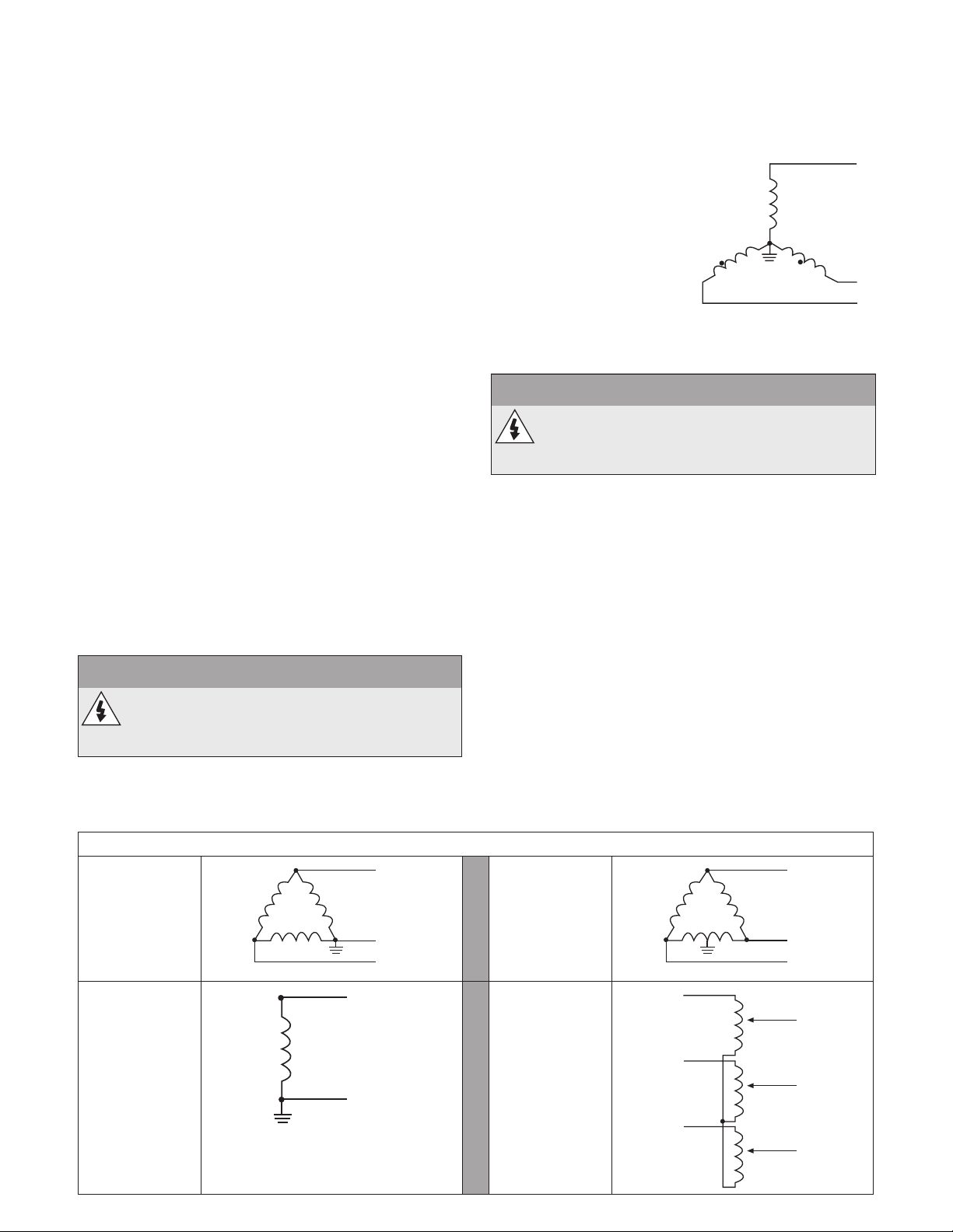
APPENDIX A: INPUT POWER
L1
L1
SPECIFICATIONS (CONTINUED)
4) Power Factor Capacitor Isolation: Input
transformers are sometimes used to provide
impedance to isolate drives from line connected
power factor correction capacitors. PWM drive
inputs do not require power factor correction
capacitors as drive power factors are generally
greater than 92% and cannot be signicantly
improved with power factor correction capacitors
which only correct for fundamental. However drives
should be isolated from power factor correction
capacitors by about 3 to 6% additional impedance
with respect to the drives. Line reactors can
perform this function much more cost effectively
than isolation transformers. SPD Plus drives have
either an internal 3% line reactor or an equivalent 3
to 5% bus reactor.
5) RFI/EMI Mitigation: Neither input isolation
transformers nor line or bus reactors provide good
high frequency ltering although an isolation
transformer with a static shield will provide some
RFI mitigation. If RFI/EMI mitigation is required,
an RFI/EMI lter mounted inside the drive should
be used together with all the proper wiring and
grounding techniques. Some RFI/EMI lters may
operate only on a power source with a grounded
neutral. Establishing a local neutral ground may
require the use of an input isolation transformer.
CORNER GROUNDED TN SYSTEMS
WARNING
Do not attempt to install or remove the EMC
lter screws EM1, EM3, F1 or F2 while power is
applied to the drive's input terminals.
Corner grounded TN systems are dened in the
following table. In such systems, disconnect the
internal ground connection through the EMC lter
capacitors (do this also if the grounding conguration
of the system is unknown), see SECTION 6: POWER
SUPPLY AND WIRING for details.
The EMC lter capacitors make an internal ground
connection that reduces electro-magnetic emission.
Where EMC (electro-
magnetic compatibility) is
a concern, and the system
is symmetrically grounded,
the EMC lter may be
connected. For reference,
the diagram on the right
illustrates a symmetrically
grounded TN system (TN-S
system).
FLOATING NETWORKS
WARNING
Do not attempt to install or remove the EMC
lter screws EM1, EM3, F1 or F2 while power is
applied to the drive's input terminals.
For IT systems (an ungrounded power system or
a high-resistance-grounded [over 30 ohm] power
system):
• Disconnect the ground connection to the internal
EMC lter, see SECTION 6: POWER SUPPLY AND
WIRING for details.
• Where EMC requirements exist, check for
excessive emission propagated to neighboring
low voltage networks. In some cases, the natural
suppression in transformers and cables is
sufcient. If in doubt, use a supply transformer
with static screening between the primary and
secondary windings.
• Do NOT install an external RFI/EMC lter. Using
an EMC lter grounds the input power through
the lter capacitors, which could be dangerous
and could damage the drive.
L2
L3
Grounded at
the corner of
the delta
Single phase,
grounded at an
end point
28
Corner Grounded TN Systems — EMC Filter must be disconnected
L1
Grounded at
the mid point
of a delta leg
L2
L3
L1
Three phase
"Variac"
without solidly
grounded
neutral
L2
N
L3
L1
L2
L3
L1
L2
L3
Page 29
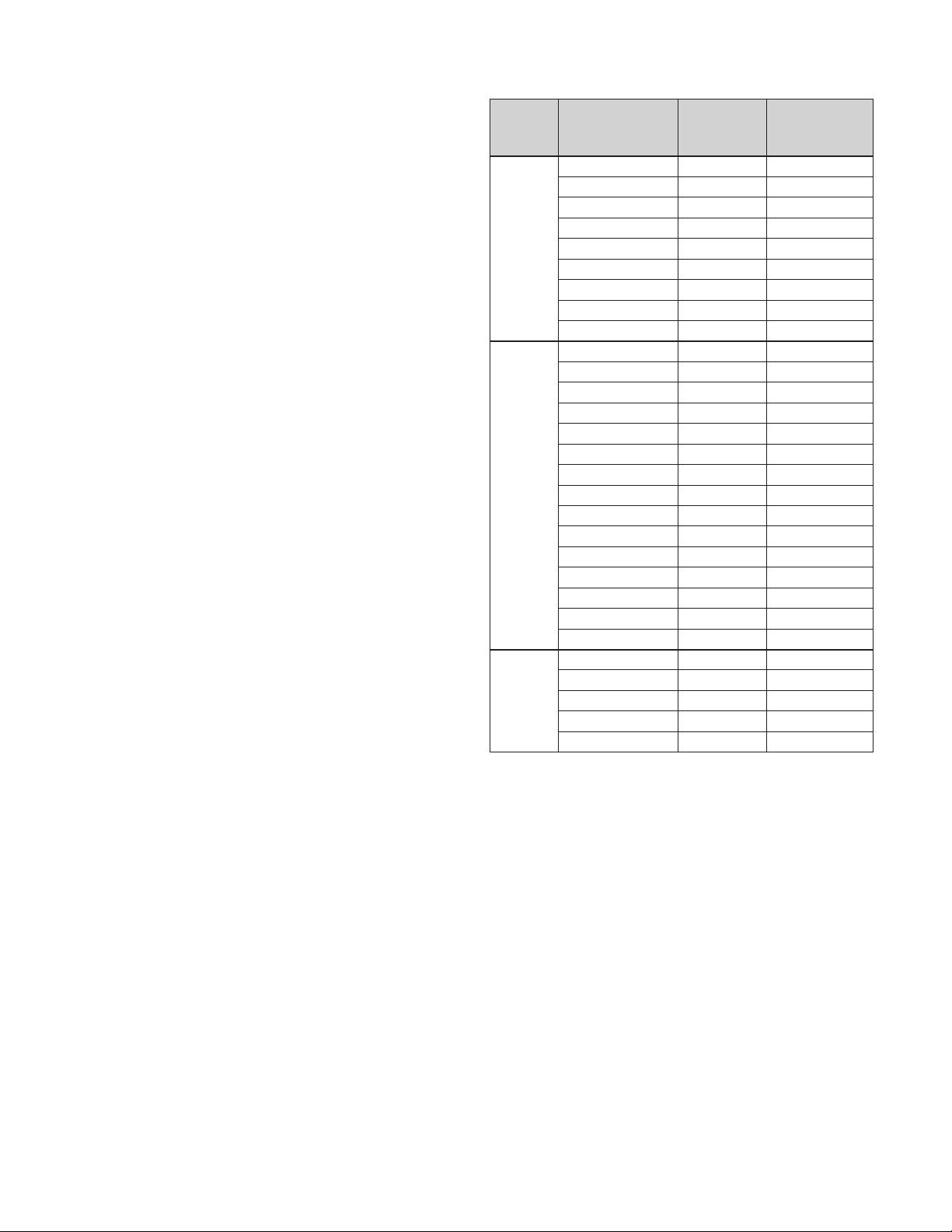
APPENDIX B: FUSE AND WIRE SIZING
FUSES
Branch circuit protection must be provided by the end
user and sized per national and local electric codes.
The following tables provide fuse recommendations
for short circuit protection on the drive's input power.
The rated fuse currents given in the tables are the
maximums for the mentioned fuse types. If smaller
fuse ratings are used, check that the fuse Arms current
rating is larger than the input current.
Check that the operating time of the fuse is below
0.5 seconds. The operating time depends on the
fuse type, the supply network impedance as well as
the cross-sectional area, material and length of the
supply cable. In case the 0.5 seconds operating time
is exceeded with the gG or T fuses, ultra rapid (aR)
fuses will in most cases reduce the operating time to
an acceptable level.
Input
Voltage
230V
460V
575V
Model
Number
SPD20400 114 150
SPD20400F 143 200
SPD20400N1 114 150
SPD20500 143 200
SPD20500F 178 250
SPD20500N1 143 200
SPD20600 178 250
SPD20600F 221 300
SPD20600N1 178 250
SPD40400 59 80
SPD40400F 72 90
SPD40400N1 59 80
SPD40500 72 90
SPD40500F 96 125
SPD40500N1 72 90
SPD40600 96 125
SPD40600F 96 125
SPD40600N1 96 125
SPD40750 124 175
SPD40750F 124 175
SPD40750N1 124 175
SPD41000 157 200
SPD41000F 157 200
SPD41000N1 157 200
SPD50400N1 52 60
SPD50500N1 77 100
SPD50600N1 77 100
SPD50750N1 99 150
SPD51000N1 144 200
Input
Current
(Arms)
Mains
Fuse Size
(UL Class T)
29
Page 30

APPENDIX B: FUSE AND WIRE SIZING (CONTINUED)
WIRE SIZING
The tables below show the maximum recommended
cable lengths for each model. Note that the tables
show the cable length which will produce a 5%
voltage drop on the cable. The recommended total
voltage drop across all system cables is 5%. Because
of this the lengths given in the table must be adjusted
so the total voltage drop does not exceed 5%. For
SPD PLUS INPUT WIRE SIZING CHARTS
MaximumAllowableConductorLength(50˚CAmbient,5%drop)
Controller
Controller
Input
230V
1Ø Input,
3Ø
Output
230V
3Ø Input,
3Ø
Output
460V
575V
Ratings
FLA
Input
Cur-
6 4 3 2 1 1/0 2/0 3/0 4/0 250 300 350 400 500 600 750 1000
rent
169.7
1636 2080
Motor HPMotor
20 54 95.4 393 505 648 826 1050 1247 1501 1760 2018 2518 3036 3810
25 68 120.2 501 642 820 978 1179 1385 1591 1989 2398 3015 3997
30 82 144.9 519 668 799 966 1137 1308 1639 1976 2490 3300
40 96
50 116 205.0 655 776 899 1135 1368 1736 2300
60 130 229.8 792
40 53 54.1 816 1043 1331 1690 2146 2723 3447
50 70 71.4 765 984
60 80 81.6 846 1084
75 96 98.0 881 1133 1456 1855
100 127 129.6 1363 1745 2083 2514 2955
40 43 43.8 784 1286
50 54 55.3 995 1273 1625
60 64 65.7 1052 1349 1719 2187
75 76 77.6 1121 1434 1832 2338
100 101 103.1 1335 1719
(LengthsinBoldRequire90˚CRatedWire)
1256
2634 3337
2064 2621
example, if the input wire sizing chart gives the
maximum length of 400' and only 100' is used then
only 25% of the total voltage drop (1.25% drop) is
used. The maximum output cable length must then
be adjusted to 75% of its value so that the maximum
voltage drop of 5% is not exceeded.
ConductorSizefor75˚CRatedWire
1601
2040 2588 3277 3882
1386
3327
558
1772
2251 2855 3385
2783 3528
2969
2193
670
2359
2802 3374 3957
3763
2792 3320
812 958
1106
3398
1389 1675
1002
1208 1538 2038
2116 2804
30
Page 31

APPENDIX B: FUSE AND WIRE SIZING (CONTINUED)
SPD PLUS OUTPUT WIRE SIZING CHARTS
MaximumAllowableConductorLength(50˚CAmbient,5%drop)
Controller
Output
230V
460V
575V
Controller
Ratings
Motor HPMotor
20 54
25 68
30 82
40 96
50 116
60 130
40 53 834 1066 1360
50 70 782 1005 1283
60 80 865 1108
75 96 901 1158 1487
100 127 1087 1393 1783 2128 2568 3018 3469
40 43 802 1315
50 54 1017 1301 1661
60
75 76 1146 1466 1871
100 101 1366
6
FLA
64 1076 1379 1756 2234
4 3 2 1 1/0 2/0 3/0 4/0 250 300 350 400 500 600 750 1000
408 522 667 846 1075 1364 1726 2181 2580 3100 3627
404 519 662 843 1074 1362 1723 2041 2454 2873 3289
420 539 689 881 1120 1420 1684 2026 2374 2720 3392
450 579 743 947 1204 1430 1722 2019 2316 2890 3484
603 771 984 1172 1413 1659 1906 2382 2871 3610
679 869 1038 1253 1472 1693 2118 2553 3214
1671
2124 2689 3407
ConductorSizefor75˚CRatedWire
(LengthsinBoldRequire90˚CRatedWire)
1726
2191
2780 3519
1635 2083
1416 1809 2298
2108 2676
3396
2842
2388
1758
2643 3346 3963
2914 3455
1894 2408 2861
3602
3032 3842
2242 2853 3391
3444
APPENDIX C: WEIGHTS AND DIMENSIONS
CONTROLLER DIMENSIONS
NEMA 1 Enclosures
NOTE
Controllers with an N1 sufx have a NEMA 1
enclosure and are rated for indoor use only.
NEMA 1 Enclosure Dimensions
Ref.
W 203 8.0 265 10.4 300 11.8
H 596 23.4 602 23.7 700 27.6
H2 583 23.0 578 22.8 698 27.5
H3 689 27.1 739 29.1 880 34.6
D 262 10.3 286 11.3 400 15.8
R4 R5 R6
mm in mm in mm in
31
Page 32
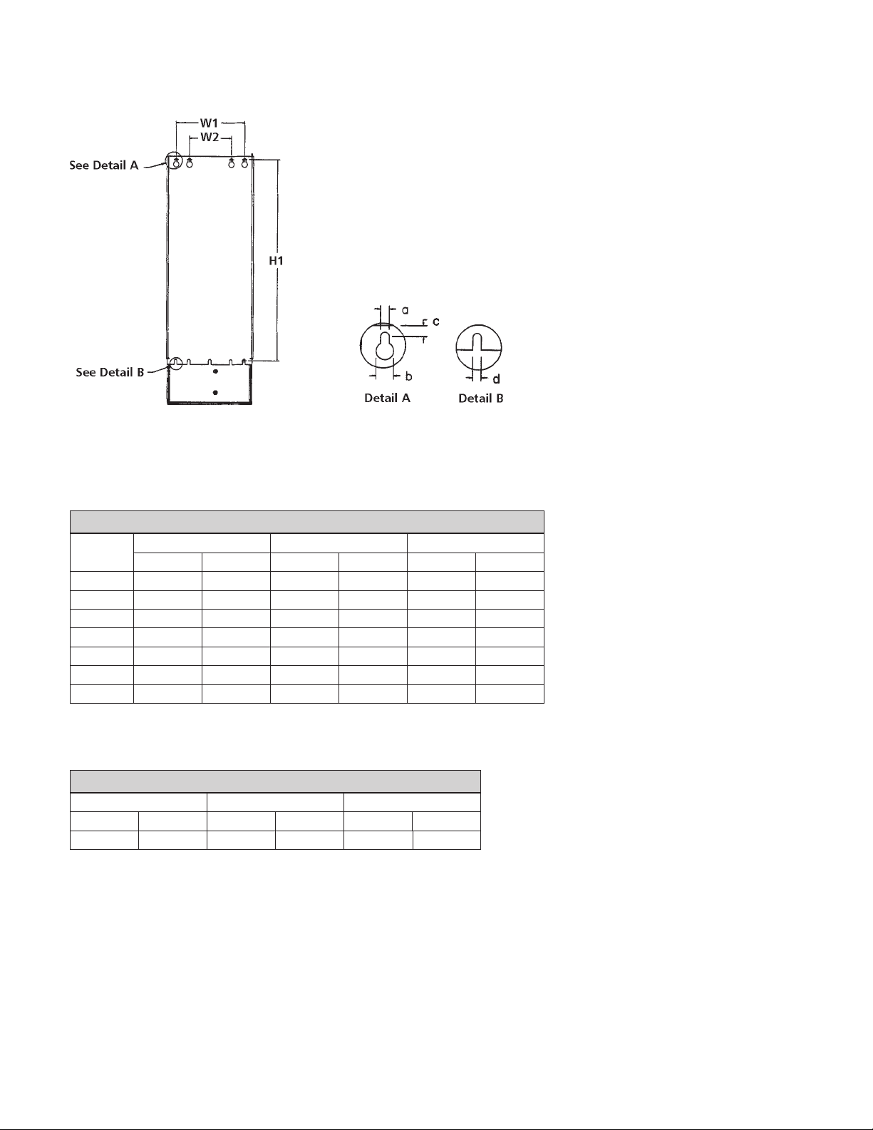
APPENDIX C: WEIGHTS AND DIMENSIONS (CONTINUED)
NEMA 1 Mounting Dimensions
Ref.
W1* 160 6.3 238 9.4 263 10.4
W2* 98 3.9 — — — —
H1* 578 22.8 588 23.2 675 26.6
a 6.5 0.25 6.5 0.25 9 0.35
b 13 0.5 14 0.55 14 0.55
c 8 0.3 8.5 0.3 8.5 0.3
d 6.5 0.25 6.5 0.25 9 0.35
*Center to center dimension.
R4 R5 R6
mm in mm in mm in
NEMA 1 Weights
R4 R5 R6
kg lb. kg lb. kg lb.
22.8 50.2 37 82 78 176
32
Page 33

APPENDIX C: WEIGHTS AND DIMENSIONS (CONTINUED)
NEMA 3R Enclosures
Frame Size N4 Frame Size N5
Frame Size N6
NEMA 3R Enclosure Dimensions
Ref.
W 530.9 20.9 762.0 30.0 914.4 36
H 967.7 38.1 990.6 39.0 1590.0 62.6
D 388.6 15.3 33.7 15.5 546.1 21.5
N4 N5 N6
mm in mm in mm in
NEMA 3R Wall Mounting Dimensions
Ref.
W1 398.8 15.7 723.9 28.5
H1 916.9 36.1 876.3 34.5
N4 N5 N6
mm in mm in mm in
Not Applicable
Self Standing Unit
NEMA 3R Weights — Without Filter
N4 N5 N6
kg lb. kg lb. kg lb.
87.5 193 92.1 203 178.7 394
NEMA 3R Weights — With Filter
N4 N5 N6
kg lb. kg lb. kg lb.
98.9 218 107.0 236 204.1 450
33
Page 34

NOTES
34
Page 35

NOTES
35
Page 36

LIMITED WARRANTY
This warranty applies to this Xylem Inc. product.
Any part or parts found to be defective within the warranty period shall be replaced at no charge to the dealer during the warranty period. The warranty period shall
exist for a period of twenty-four (24) months from date of installation or thirty (30) months from date of manufacture, whichever period is shorter.
A dealer who believes that a warranty claim exists must contact the authorized Xylem Inc. distributor from whom the equipment was purchased and furnish complete
details regarding the claim. The distributor is authorized to adjust any warranty claims utilizing the Xylem Inc. Customer Service Department.
The warranty excludes:
(a) Labor, transportation and related costs incurred by the dealer;
(b) Reinstallation costs of repaired equipment;
(c) Reinstallation costs of replacement equipment;
(d) Consequential damages of any kind; and,
(e) Reimbursement for loss caused by interruption of service.
Forpurposesofthiswarranty,thefollowingtermshavethesedenitions:
(1) “Distributor” means any individual, partnership, corporation, association, or other legal relationship that stands between Xylem Inc. and the dealer in purchases,
consignments or contracts for sale of the subject equipment.
(2) “Dealer” means any individual, partnership, corporation, association, or other legal relationship which engages in the business of selling or leasing equipment to
customers.
(3) “Customer” means any entity who buys or leases the subject equipment from a dealer. The “customer” may mean an individual, partnership, corporation, limited
liability company, association or other legal entity which may engage in any type of business.
THIS WARRANTY EXTENDS TO THE DEALER ONLY.
Xylem, Inc.
2881 East Bayard Street Ext., Suite A
Seneca Falls, NY 13148
Phone: (800) 453-6777
Fax: (888) 322-5877
www.centripro.com
CentriPro and Aquavar are trademarks of Xylem, Inc. or one of its subsidiaries.
© 2012 Xylem Inc. IM244 Rev. 4 July 2013
 Loading...