

Page 1
INSTRUCTION MANUAL
IM226R02
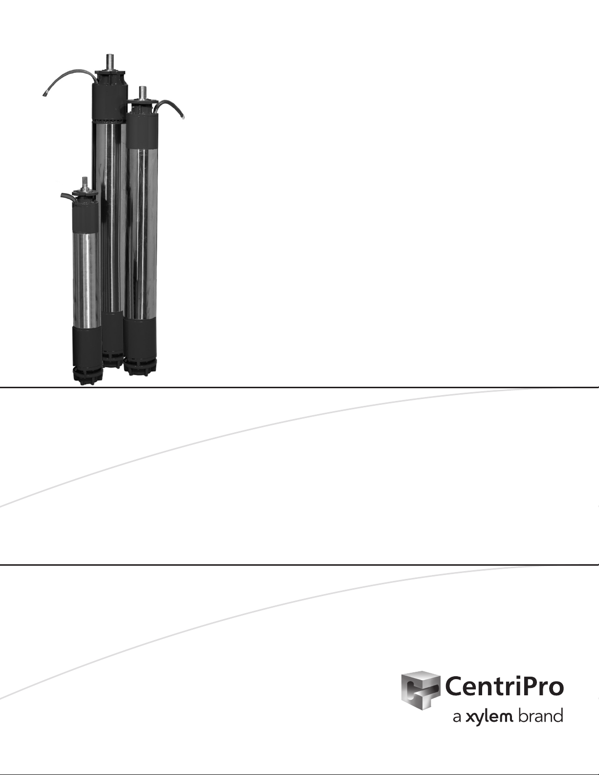
CP-Series
Submersible Motors
INSTALLATION, OPERATION AND MAINTENANCE INSTRUCTIONS
Page 2

2 CP-Series Submersible Motors Installation, Operation and Maintenance Manual
Page 3

Table of Contents
Table of Contents
Safety Instructions ...................................................................................................................................................................... 2
Overview and Product Description ......................................................................................................................................... 3
Handling and Installation ................................................................................................................................................... 4, 6-9
Submersible Pump Installation Diagram ................................................................................................................................ 5
Guidelines For VFD Control of CP Series Rewindable Submersible Motors ..........................................................10, 11
Pre-Installation ..........................................................................................................................................................................12
Maintenance ............................................................................................................................................................................... 13
Operation ...................................................................................................................................................................................13
Tables 1 – 8 .......................................................................................................................................................................... 14-19
Three Phase 75º C Cable, 60 Hz ............................................................................................................................................19
Troubleshooting of Submersible Motors ..............................................................................................................................20
Motor Cooling, Temperature Ratings ....................................................................................................................................21
Limited Warranty....................................................................................................................................................................... 22
Owners Information
Complete this information for your records.
Model number and serial number may be found
on the tag mounted to the pump casing.
Pump Model Number
Pump Serial Number
Control Model Number
____________________________________________
Dealer
Dealer phone number
Date of purchase
Date of installation
Current Readings at Startup:
1 Ø 3 Ø L1-2 L2-3 L3-1
Amps: Amps:
Volts: Volts:
_______________________________
________________________________
_____________________________
_______________________________
___________________________________
_________________________________ _
CP-Series Submersible Motors Installation, Operation and Maintenance Manual 1
Page 4
DANGER
CAUTION
N OTICE
Safety
I. Safety
TO AVOID SERIOUS OR FATAL PERSONAL INJURY OR MAJOR PROPERTY DAMAGE,
READ AND FOLLOW ALL SAFETY INSTRUCTIONS IN MANUAL AND ON PUMP.
THIS MANUAL IS INTENDED TO ASSIST IN THE INSTALLATION AND OPERATION OF THIS
UNIT AND MUST BE KEPT WITH THE PUMP.
Indicates an imminently hazardous situation which, if not avoided, will result in death or
serious injury.
WARNING
CAUTION
THOROUGHLY REVIEW ALL INSTRUCTIONS AND WARNINGS PRIOR TO PERFORMING
ANY WORK ON THIS PUMP.
MAINTAIN ALL SAFETY DECALS.
Indicates a potentially hazardous situation which, if not avoided, will result in death
or serious injury. Hazards identied by the signal word WARNING present a lesser
degree of risk of injury or death than those identied by the signal word DANGER.
Indicates a potentially hazardous situation which, if not avoided, may result in minor or
moderate injury. CAUTION may also be used to alert against unsafe practices associated
with events that could lead to personal injury.
Used without the Safety Alert Symbol indicates a potentially hazardous situation which,
if not avoided, may result in property damage.
Indicates a statement of company policy directly or indirectly related to the safety of
personnel or protection of property.
2 CP-Series Submersible Motors Installation, Operation and Maintenance Manual
Page 5

CAUTION
N OTICE
II. Overview
This manual gives important information concerning the installation, use and maintenance of the motors.
The contents of this manual refer to the standard product, as presented in the sales documentation. Any
special versions will be supplied with supplementary instruction sheets. Please refer to the sales contract for
the features of variants and special versions. Always specify the exact type of motor and code when requesting our Sales and Service Department for technical information or spare parts. For any instructions, situations
and events not covered in this manual or in the sales documentation, please contact the nearest Technical
Assistance Center.
Read this manual carefully before installing and using the product.
Improper use may cause personal injury and/or damage to property, and invalidate the warranty.
III. Product Description
The CentriPro CP-Series comprises 6”, 8”, 10” and 12” submersible rewindable motors with stator and rotor
immersed in a bath of lubricating liquid consisting of demineralised water and anti-freeze. 6" and 8" motors
are equipped with NEMA-standard ange and shaft dimensions. For 10" and 12" motor sizes please consult
this product's technical bulletin for mounting dimensional details.
Overview and Product Description
All the metal parts in contact with the water are either made from stainless steel or cast iron.
Each motor includes a Kingsbury pivoted-shoe thrust bearing and winding wire. The winding wire will be
either standard or special high temperature type.
CP-Series Submersible Motors Installation, Operation and Maintenance Manual 3
Page 6

Handling and Installation
IV. Handling and Installation
1. Do not use lead wires to pull, lift or handle the motor. The lead wires should be protected during storage,
handling, moving and installation of the motor.
2. Inspect the motor to determine that it is the correct HP, voltage and size for the job and that there is no
shipping damage.
3. The factory-installed water in the motor is supplied with antifreeze capable of temperatures to -5º C (23º F).
Do not install, transport or store below these temperatures. If storage is necessary below these temperatures,
drain the water from the motor.
4. After long periods of idleness and on all new installations, check the electrical resistance and megger the
motor with lead wires connected. The insulation resistance should have a value of at least 5 megohms at
installation and at least 1 megohm after running.
5. Verify motor is lled with clean water before installing. The warranty is void if this is not done. Also check
the tightness of all water lling and drain plugs, mounting bolts and cable connections.
6. Do not hammer the shaft, coupling or slinger since this may damage the thrust bearing. Check the rotation
of the motor by hand to insure that it turns freely.
7. Do not drop the bottom end of the motor in the dirt or mud since this may plug up the diaphragm opening.
8. If motor is to be installed horizontally, make sure the relief valve is at the 12 o'clock position when facing the
motor shaft (in horizontal position).
9. Check that winding coil resistance in each two phases is equal to values in Tables 1 - 4.
10. Select the proper overload relay or heaters.
11. For 50HP and 60HP models: Remove the metal sleeve attached to the midpoint of the motor and discard.
4 CP-Series Submersible Motors Installation, Operation and Maintenance Manual
Page 7
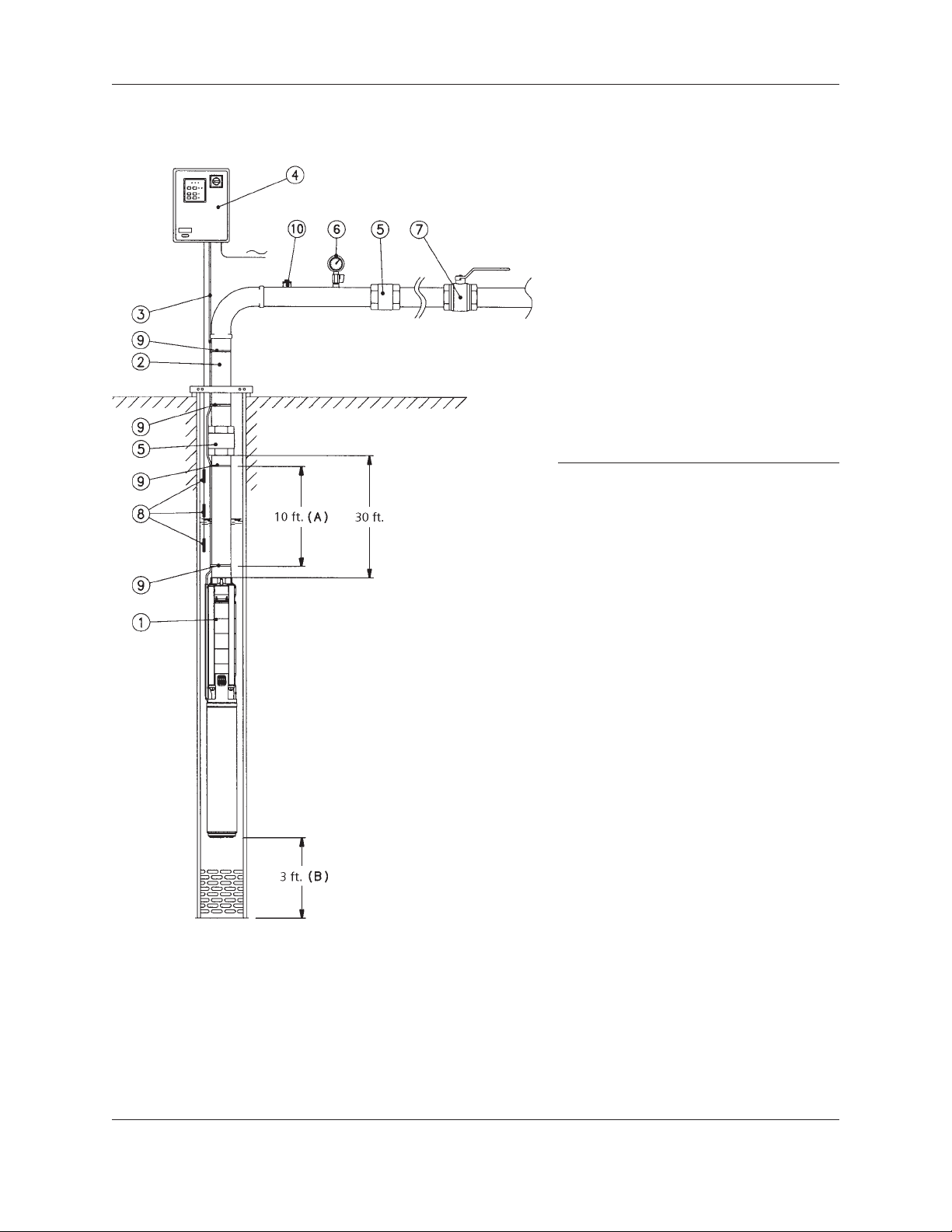
Submersible Pump Installation Diagram
Submersible Pump Installation Diagram
1 - Submersible pump
2 - Delivery pipe
3 - Drop cable
4 - Control panel
5 - Check valve
6 - Gauge
7 - Gate valve
8 - Level sensors for protection against dry
running.
9 - Cable clamp
10 - Pump bleed/priming cap
A - Distance between the clamps that secure
the drop cable to the delivery pipe.
B - Distance from the bottom of the well to
the electric motor.
COMPONENTS REQUIRED FOR CORRECT INSTALLATION
• Control panel equipped with a main switch and thermal relay for
overload protection.
• Check valve at 30 feet distance from the delivery ports, plus an
additional non-return valve every 100-165 feet of piping.
• Gauge and gate valve at well mouth.
• Electronic probes or oats for protection against dry running.
RECOMMENDATIONS
• Secure the drop cable to the pipe every 6-10 feet of piping.
• Make sure the motor is installed at a safe distance from the bottom of
the well.
• Make sure there is a minimum distance of .13 inches between the
diameter of the pump and the internal diameter of the well.
• During operation, make sure that the water circulation speed around the
motor is per Section VI #1.
• Make sure that the minimum dynamic level of the water in the well is at
least 3 feet above the pump’s delivery port.
CP-Series Submersible Motors Installation, Operation and Maintenance Manual 5
Page 8
Handling and Installation (continued)
CAUTION
CAUTION
CAUTION
N OTICE
N OTICE
WARNING
IV. Handling and Installation (continued)
Before installing the motor, read this instruction manual and the one supplied with the pump
or electric pump to which the motor will be coupled. Keep both manuals in a safe place for
future reference.
Selecting the electrical panel
Make sure the panel power ratings match those of the pump. Incompatible combinations
may cause faults and fail to fully protect the motor.
Before installing, carefully read the instructions supplied with the electrical panel.
Checking the motor liquid level
Place the motor in the vertical position, with the air valve facing upwards. Unscrew the air
valve from its hole. Add clean water using a syringe, until the water overows the hole. Make
sure the valve is not clogged. If necessary, clean it or replace it. Screw the valve back into the hole.
Installation in a well or tank
When installing the electric pump vertically, make sure the motor does not rest on the bottom of the
well or tank.
When installing the electric pump horizontally, make sure the motor does not rest on the bottom of the tank.
Electrical connections to the electric motor
Make sure that the supply voltage and frequency are compatible with the electrical panel. The
relative information is shown on the motor rating plate and in the documents supplied with
the panel. Provide suitable short circuit protection on the supply line.
Before proceeding, make sure that all the connections (even if they are potential-free) are
Risk of
electrical shock.
Disconnect
power before
servicing.
voltage-free. Unless otherwise specied in local bylaws, the supply line must be tted with:
• a short circuit protection device
• a high sensitivity residual current circuit breaker (30mA) for additional protection from
electrocution in case of inefcient grounding.
• a disconnect switch with a contact aperture of at least 3 mm.
Ground the system in compliance with current regulations. Attach the included lead wire to the upper endbell.
6 CP-Series Submersible Motors Installation, Operation and Maintenance Manual
Page 9

Power Cable Connection Diagrams
6" Direct Starting (1 cable)
Handling and Installation (continued)
6"
RD
BK
YE
GN
BK - Black RD - Red YE - Yellow GN - Green
8", 10", 12" Direct Starting (1 cable)
8"-10"-12"
BK
RD
1
2
3
43~PE
U1
V1
3~
1
2
3
1
2
3
U1
V1
W1
L1
L2
L3
L1
L3
L2
L1
L2
L3
YE
GN
BK - Black RD - Red
8", 10", 12" Direct Starting (2 cables)
BK
8"-10"-12"
RD
YE
BK
RD
YE
GN
W1
U2
V2
W2
U1
V1
W1
PE
PE
3~
U1
U2
V1
V2
W1
W2
U1
U2
V1
V2
W1
W2
U1
V1
W1
L1
L3
L2
GNYE - GreenYE - Yellow
L1
L2
L3
L1
L3
L2
BK - Black RD - Red
CP-Series Submersible Motors Installation, Operation and Maintenance Manual 7
YE - Yellow GN - Green
Page 10

Handling and Installation (continued)
Y
Power Cable Connection Diagrams
(continued)
6", 8", 10", 12" Star/Delta version with direct starting at lower voltage
U1
W2
V1
U2
W1
V2
U1
W2
U1
V2
W1
V2
YE - Yellow GN - Green
6"-8"-10"-12"
BK
U2
RD
V2
YE
W2
BK
U1
RD
V1
YE
W1
GN
BK - Black RD - Red
3~
PE
6", 8", 10", 12" Star/Delta version with direct starting at higher voltage
L1
L2
L3
L1
L3
L2
6"-8"-10"-12"
BK
U2
RD
V2
YE
W2
BK
U1
RD
V1
YE
W1
GN
BK - Black RD - Red
PE
U1
V1
W1
W2
U2
V2
3~
U1
V1
W1
W2
U2
V2
YE - Yellow GN - Green
L1
L2
L3
L1
L3
L2
8 CP-Series Submersible Motors Installation, Operation and Maintenance Manual
Page 11

PTC Temperature Probe
Handling and Installation (continued)
PTC
RD
RD
W
PT100 Temperature Probe
PT100 (RTD)
RD
RD
U
WH
U
NOM 2,5" 7,5V
U
30V
MAX
EM
I
EM
Ω
≥ 1330
≤ 550
≤ 250
PTC, PT100
U
2,5 V
NOM
+
T
REF
5
…C
-20
-5
Ω
313
100
…C
0 …C
600 …C T
REF
RD - Red WH - White
EM - Electronic Module I - Measured Variable Current U - Input Voltage
U
nom - Rated Input Voltage Umax - Maximum Input Voltage Tref - Reference Temperature
CP-Series Submersible Motors Installation, Operation and Maintenance Manual 9
Page 12

Guidelines for VFD Control
V. Guidelines For VFD Control of
CentriPro CP-Series Rewindable
Submersible Motor
Variable Frequency Drives together with submersible pumps are today often being used when water demand
varies over time. The pump will run with the VFD at a speed optimal to the actual demand, leading to possible
energy savings.
There are a wide number of different frequency drives available on the market and they often have different
characteristics. Therefore it is important to choose a VFD and other electric components that will work
satisfactory together with the motor. VFDs generate voltage peaks and if the peaks are too high and too steep
they will damage the windings in any submersible motor.
The CentriPro CP Series submersible motors can be used with Variable Frequency Drives if the following
guidelines are followed.
Frequency Limitations
You should never run the motor with the VFD on a higher frequency than the data plate on the motor states.
With a higher frequency than stated, overload and overheating problems could occur. Generally you are never
allowed to run the pump with a frequency below 30Hz. Always make sure that the ow around the motor is
enough to cool the motor at all the duty points of operation. Values for the ow can be found in the
submersible motor technical catalogue.
Ramp Up and Ramp Down Time
The ramp up time to the minimum running frequency should be set as quick as possible (maximum 1s) to ensure
the correct lubrication of the thrust bearing in the motor. The ramp down time (from the minimum running
frequency to 0 Hz) should be set as quick as possible (maximum 1s) as well.
Filters
Filters for reducing voltage peaks and steepness generated by the VFD are recommended and should be speci-
ed by the VFD manufacturer according to the below voltage peak and rise time limits.
Voltage Drop with Long Cables
The VFD should be installed as close as possible to the motor. When this is not possible a maximum of 4%
voltage drop at the motor is acceptable.
Use of VFD with CentriPro CP Series Submersible HT Motors (high temperature version)
It is always recommended the use of HT motors with VFD operation. The reason for this is that the
HT version has a higher tolerance for voltage peaks. For HT motors the voltage peaks to the pump may never
exceed 1000 Volts and the voltage rise time dV/dt should be lower than 500V/μs. If the VFD can not full this
recommendation lters between the VFD and the motor has to be used. The requirement will then be that the
VFD together with the lters does not generate higher peaks than 1000V and that the voltage rise time dV/dt
should be lower than 500V/μs. The following indications are also recommended: use of dV/dt lters in case
of motors cable length ≤ 100 and use of sine wave lters for longer cable.
10 CP-Series Submersible Motors Installation, Operation and Maintenance Manual
Page 13

Guidelines for VFD Control (continued)
Use of VFD with CentriPro CP Series Submersible Standard Motor
Standard CentriPro CP Series motors can be used if it can be guaranteed that the VFD will not generate higher
voltage peaks than 690V and if voltage rise time dV/dt is lower than 500V/μs. If the VFD can not full this
recommendation lters between the VFD and the motor has to be used. The requirement will then be that the
VFD together with the lters does not generate higher peaks than 690V and that the voltage rise time dV/dt
should be lower than 500V/μs. However it is always recommended the use of sine wave lters.
Water Temperature and VFD Use
Together with VFD we recommend the usage of the High Temperature (HT version) of the motor up to 30°C
of water temperature. For higher water temperatures a derating of the motor should be made.
Derating of the motor depends on the quality of the output from the VFD. If the quality is close to the quality
of the supply without VFD then there is no special restriction regarding water temperature for VFD use. Refer
to the technical catalogue for submersible motors for water temperature limits.
End Notes
If the installation requires operation other than stated in the guidelines or if questions arise that are not covered
in the guidelines please contact Xylem Inc. customer service for guidance. The toll free number for customer
support is 1-877-833-2872.
Please note that Xylem Inc. reserves the right to disclaim the warranty in case of: a) the product is out of standard warranty period; b) the defect is a consequence of use or installation in a manner contrary to the Supplier’s
instructions; c) technical analysis show that the above VFD guidelines or general motor guidelines have not been
followed.
CP-Series Submersible Motors Installation, Operation and Maintenance Manual 11
Page 14

Pre-Installation
CAUTION
VI. Pre-Installation
1. Maximum Water Temperature:
A) Standard Version: 30° C (86° F)
Must maintain ow rate of .75 fps (5 - 10 HP), 1.0 fps (15 - 30 HP), 1.75 fps (40 HP and greater). For
temperatures above 30° C (86° F), motor output must be reduced to ensure
correct cooling: maximum temperature allowed is 35° C (95° F).
B) HT Version: 45° C (113° F)
Must maintain ow rate of .75 fps (5 - 10 HP), 1.0 fps (15 - 30 HP), 1.75 fps (40 HP and greater). For
temperatures above 45° C (113° F), motor output must be reduced to ensure
correct cooling: maximum temperature allowed is 60° C (140° F).
2. PH content of the water between: 6.5–8
3. Maximum Chlorine Content: 500 PPM
Maximum Sulfuric Acid Iron Content: 15 PPM
Maximum Flourine Content: 0.8 PPM
Maximum Electric Conductivity: 118 μMHO/INCH
4. Maximum Sand Content: 50 PPM
5. Proper approved three phase overload protection. Class 10, quick trip overloads are mandatory.
See Tables 1 - 4, 9 or 10.
6. Proper fusing for motor circuit protection. See Table 5.
7. Proper Line Voltage During Running Conditions:
460V ±10%, i.e. 506 to 414 volts
230V ±10%, i.e. 253 to 207 volts at 60 cycle system at motor lead wire terminal. (Voltage drop of cable
should be considered by user.)
Combination of Voltage and Frequency Variation: ±10% (sum of absolute values of voltage and frequency).
Phase Unbalance: ±5% (3 phase)
8. Proper sizing of motor (current, thrust, voltage, etc.) and a 10 feet clearance from the bottom of the well are
required.
9. In the case of horizontal installation, the motor is to be rigidly aligned with the pump and rmly mounted to
prevent any load on the shaft and bearings and to avoid any damaging vibrations to the motor. Also, see #8
in Section IV.
10. The maximum depth of immersion for all motors is 1,150 ft (350 m).
11. The power cables shall be sized large enough so that at rated current there will be less than a 5% voltage
drop. Cables must be waterproof submersible type.
12. For 3Ø motors a balanced and properly sized transformer bank shall be provided. Improper electrical supply
(for example, phase converter, V-connection transformer, etc.) or connections will void the warranty.
13. Single phase protection is recommended for protection of the installation. Any failure due to single phasing
of the incoming voltage causing the motor to fail will void the warranty.
14. Lightning arrestors are recommended in the interest of protecting the control panel, as well as the insulation
system of the motor. Any motor failure due to lightning or other Acts of God will void the warranty.
15. Provide waterproof insulation splices between all lead wires and well cables.
16. In the event that a reduced voltage starter is used to start the motor, the following should be veried:
A. Correct quick trip ambient compensated overloads are incorporated.
B. Proper short circuit protection is utilized.
C. The torque required by the motor and pump package is attainable by this type starter.
12 CP-Series Submersible Motors Installation, Operation and Maintenance Manual
Page 15

Pre-Installation (continued), Maintenance and Operation
D. The lead arrangement of the motor is acceptable with the proposed starter load connections.
E. Verify that if any time delay relays are used in switching contactors in and out, that the time settings are
not too long; this could damage the motor.
F. If a manual auto transformer starter is used, don't wait too long to go into the "Run" condition and don't
"tease" the contacts. Double check Tables 1 - 4 for correct protection.
17. Do not expose motor leads to air. Leads must be submerged for cooling.
VII. Maintenance
There are no bearings that need oil or grease. The motor, being inaccessible, should be monitored through its
electrical connections.
1. Measure and record operating current and voltage.
2. Measure and record the motor insulation resistance. Any resistance of less than 5 megohm (5,000,000) for a
new motor should be evaluated or checked further by a qualied service shop.
3. Lightning arrestors and/or surge capacitors will help prevent damage to the control box, cables and motor.
4. Single phase protection will help in preventing motor failure due to adverse incoming primary power.
5. Based on the values obtained in 1 and 2 above and the output ow rates and pressures of the pump, a
complete picture of total performance can be obtained. This can be used to determine any pump and motor
maintenance and overhauling which might be required.
6. If the motor is to be stored, protect the unit from freezing by storing in an area with a temperature
higher than -30º C (-22º F).
VIII. Operation
1. After energizing the motor, check the ow and pressure of the pump to make sure that the motor is
rotating in the correct direction. To correct a wrong rotation, switch any two of the three cable connections.
(Three phase motor only.)
2. When starting the pump for the rst time, inspect the water for sand. If sand appears, then continue to
pump until the water clears up; otherwise, sand will accumulate in the pump stages and will bind or freeze
the moving parts if water is allowed to ow back down the well.
3. During testing or checking rotation (such as "bumping" or "inching") the number of "starts" should be
limited to 3, followed by a full 15 minute cooling-off period before any additional "starts" are attempted.
Depending on the depth of the well and/or method of checking, these rotational checks or "starts" may
actually be full-edged starts. If this is the case, then a full cooling-off
period of 15 minutes is required between this type of start.
4. For automatic (pilot device) operation, the motor should be allowed to cool for 15 minutes
between starts.
5. Input voltage, current and insulation resistance values should be recorded throughout the life of the
installation and should be used as a form of preventive maintenance.
6. Maximum number of starts per hour:
6”: 15 starts/hour
8”: 10 starts/hour
10”: 8 starts/hour
12”: 4 starts/hour
CP-Series Submersible Motors Installation, Operation and Maintenance Manual 13
Page 16

Operation (continued)
TABLE 1 — 6" Three Phase Motors, 200, 230, 380 and 460 volt
Motor Rated Rated Operating Characteristics Direct On-Line Service SF SF
Type Power Voltage At Rated Power Starting Factor Watts Amps
Three
Phase /In /Tn /Tn
P6..5T206A 200 5.48 19.0 3490 73.0 0.83 4.72 1.29 2.02 6.34 21.3
P6..5T236A
P6..5T386A 380 5.48 9.94 3490 73.0 0.84 4.75 1.29 2.02 6.35 11.2
P6..5T466A 460 5.48 8.09 3485 73.0 0.85 4.82 1.29 2.02 6.38 9.16
P6..7T206A 200 7.17 25.3 3490 76.7 0.82 5.54 1.60 2.55 8.26 28.1
P6..7T236A
P6..7T386A 380 7.21 13.7 3495 76.3 0.80 5.38 1.60 2.55 8.28 15.1
P6..7T466A 460 7.17 10.9 3490 76.8 0.82 5.59 1.60 2.55 8.26 12.2
P6..10T206A 200 9.52 32.9 3485 78.8 0.84 5.70 1.70 2.50 11.0 36.8
P6..10T236A
P6..10T386A 380 9.52 17.4 3490 78.8 0.83 5.67 1.70 2.50 11.0 19.4
P6..10T466A 460 9.51 14.1 3485 78.9 0.84 5.78 1.70 2.50 11.0 15.8
P6..12T206A 200 11.6 40.9 3485 79.9 0.82 5.84 1.85 2.70 13.4 45.6
P6..12T236A
P6..12T386A 380 11.6 21.3 3485 79.9 0.83 5.90 1.85 2.70 13.4 23.8
P6..12T466A 460 11.6 17.3 3480 80.0 0.84 6.00 1.85 2.70 13.4 19.5
P6..15T206A 200 13.6 46.2 3475 80.8 0.85 5.82 1.53 2.57 15.8 52.3
P6..15T236A
P6..15T386A 380 13.6 24.7 3480 80.7 0.84 5.73 1.53 2.57 15.8 27.8
P6..15T466A 460 13.6 20.2 3475 80.8 0.85 5.79 1.53 2.57 15.8 22.8
P6..17T206A 200 16.0 56.0 3485 81.2 0.83 5.74 1.67 2.55 18.5 62.5
P6..17T236A
P6..17T386A 380 16.0 29.5 3485 81.2 0.82 5.74 1.67 2.55 18.5 32.9
P6..17T466A 460 16.0 23.3 3475 81.4 0.86 6.00 1.67 2.56 18.6 26.4
P6..20T206A 200 18.0 62.1 3470 83.3 0.84 6.49 1.94 3.03 20.9 69.8
P6..20T236A
P6..20T386A 380 18.0 32.5 3470 83.3 0.84 6.52 1.94 3.03 20.9 36.6
P6..20T466A 460 18.0 27.2 3475 83.3 0.83 6.44 1.94 3.03 20.9 30.5
P6..25T206A 200 22.1 74.5 3475 83.9 0.86 6.85 2.40 3.11 25.6 84.0
P6..25T236A
P6..25T386A 380 22.1 40.4 3485 83.8 0.83 6.65 2.40 3.11 25.5 45.1
P6..25T466A 460 22.0 32.6 3480 83.9 0.85 6.81 2.40 3.11 25.5 36.7
P6..30T206A 200 26.0 94.7 3500 84.5 0.79 5.71 0.98 2.96 30.2 106
P6..30T236A
P6..30T386A 380 26.0 47.5 3495 84.6 0.83 5.99 0.98 2.96 30.3 53.9
P6..30T466A 460 26.0 40.0 3500 84.7 0.82 5.88 0.98 2.96 30.2 45.0
P6..35T386A
P6..35T466A 460 30.6 47.8 3495 85.0 0.80 6.10 1.18 2.82 35.4 53.7
P6..40T386A
P6..40T466A 460 35.5 53.9 3505 84.5 0.83 6.28 2.49 2.75 41.2 61.0
P6..50T386A
P6..50T466A 460 44.3 68.6 3490 83.6 0.81 5.61 1.32 2.63 51.5 77.1
P6..60T386A*
P6..60T466A* 460 54.0 82.1 3521 83.4 0.83 5.59 1.81 2.75 62.8 92.8
Ts/Tn = ratio between starting torque and nominal torque. Is/In = ratio between starting and FL amps.
Tmax/Tn = ratio between maximum torque and nominal torque. *Indicates tandem rotor design.
14 CP-Series Submersible Motors Installation, Operation and Maintenance Manual
HP kW V kW A RPM EFF PF
230 5.50 17.3 3500 72.8 0.80 4.51 1.28 2.01
5.5 4
7.5 5.5
10 7.5
12.5 9.3
15 11
17.5 13
20 15
25 18.5
30 22
35 26
40 30
50 37
60 45
230 7.30 24.3 3505 75.4 0.75 5.01 1.59 2.54
230 9.60 30.6 3500 78.2 0.79 5.33 1.69 2.49
230 11.7 37.6 3495 79.4 0.78 5.52 1.84 2.69
230 13.7 43.5 3490 80.3 0.79 5.38 1.52 2.56
230 16.1 52.5 3495 80.5 0.77 5.33 1.66 2.55
230 18.1 56.4 3485 83.1 0.80 6.21 1.93 3.02
230 22.2 71.1 3495 83.4 0.78 6.24 2.39 3.10
230 26.0 83.1 3505 84.5 0.79 5.66 0.98 2.96
380 30.6 59.8 3500 85.0 0.78 5.90 1.18 2.82
380 35.5 64.9 3500 84.4 0.83 6.31 2.49 2.75
380 44.4 86.2 3495 83.4 0.78 5.40 1.32 2.63
380 54.0 99.4 3521 83.4 0.83 5.59 1.81 2.75
Is Ts Tmax
SF kW A
6.30 19.0
1.15
8.33 26.4
1.15
11.0 33.6
1.15
13.4 41.3
1.15
15.8 47.9
1.15
18.6 57.4
1.15
20.9 62.5
1.15
25.5 78.2
1.15
30.2 92.6
1.15
35.4 66.5
1.15
41.1 72.6
1.15
51.4 95.9
1.15
62.8 112
1.15
Page 17

Operation (continued)
TABLE 2 — 8" Three Phase Motors, 380 and 460 volt
Motor Rated Rated Operating Characteristics Direct On-Line Service SF SF
Type Power Voltage At Rated Power Starting Factor Watts Amps
Three
Phase /In /Tn /Tn
P8..40T386A
P8..40T466A 460 56.0 64.4
P8..50T386A
P8..50T466A 460 69.0 79.4
P8..60T386A
P8..60T466A 460 82.0 94.3
P8..70T386A
P8..70T466A 460 96.0 110
P8..75T386A
P8..75T466A 460 100 115
P8..80T386A
P8..80T466A 460 107 123
P8..90T386A
P8..90T466A 460 121 139
P8..100T386A
P8..100T466A 460 134 154
P8..110T386A
P8..110T466A 460 148 170
P8..125T386A
P8..125T466A 460 166 191
Ts/Tn = ratio between starting torque and nominal torque. Is/In = ratio between starting and FL amps.
Tmax/Tn = ratio between maximum torque and nominal torque.
HP kW V kW A RPM EFF PF
40 30
50 37
60 45
70 52
75 55
80 60
90 67
100 75
110 83
125 93
380
380
380
380
380
380
380
380
380
380
67.8
37.0
83.5
45.6
99.3
54.2
116
62.7
121
66.1
130
71.6
146
80.0
162
89.7
179
99.1
201
111
3470 81.5 0.83 5.50 1.04 2.22 1.15 43.0
3475 81.5 0.83 5.26 1.04 2.23 1.15 53.5
3480 83.0 0.83 4.98 0.98 2.22 1.15 62.0
3475 83.0 0.82 5.56 1.06 2.22 1.15 73.0
3475 83.5 0.83 5.44 1.06 2.24 1.15 77.5
3480 84.0 0.84 5.07 1.04 2.23 1.15 83.0
3480 84.0 0.83 5.13 1.03 2.23 1.15 95.0
3485 84.0 0.84 5.04 1.01 2.22 1.15 108
3485 84.0 0.84 4.79 0.97 2.28 1.15 118
3490 84.0 0.84 4.60 1.02 2.22 1.15 129
Is Ts Tmax
SF kW A
78.0
96.1
114
134
139
149
168
187
206
231
TABLE 3 — 10" Three Phase Motors, 380 and 460 volt
Motor Rated Rated Operating Characteristics Direct On-Line Service SF SF
Type Power Voltage At Rated Power Starting Factor Watts Amps
Three
Phase /In /Tn /Tn
P10..125T386A
P10..125T466A 460 164 189
P10..150T386A
P10..150T466A 460 200 225
P10..175T386A
P10..175T466A 460 236 271
P10..200T386A
P10..200T466A 460 272 313
Ts/Tn = ratio between starting torque and nominal torque. Is/In = ratio between starting and FL amps.
Tmax/Tn = ratio between maximum torque and nominal torque.
CP-Series Submersible Motors Installation, Operation and Maintenance Manual 15
HP kW V kW A RPM EFF PF
125 93
150 110
175 130
200 150
380
380
380
380
199
110
242
131
286
152
329
176
3510 85.0 0.84 5.55 1.02 2.22 1.15 130
3520 85.5 0.82 6.38 1.43 2.19 1.15 149
3520 85.5 0.81 6.31 1.50 2.22 1.15 174
3525 85.5 0.81 6.24 1.56 2.22 1.15 191
Is Ts Tmax
SF kW A
229
272
328
379
Page 18

Operation (continued)
TABLE 4 — 12" Three Phase Motors, 380 and 460 volt
Motor Rated Rated Operating Characteristics Direct On-Line Service SF SF
Type Power Voltage At Rated Power Starting Factor Watts Amps
Three
Phase /In /Tn /Tn
P12..250T386A
P12..250T466A 460 320 368
P12..300T386A
P12..300T466A 460 385 443
P12..350T386A
P12..350T466A 460 447 514
P12..400T386A
P12..400T466A 460 512 589
Ts/Tn = ratio between starting torque and nominal torque. Is/In = ratio between starting and FL amps.
Tmax/Tn = ratio between maximum torque and nominal torque.
HP kW V kW A RPM EFF PF
250 185
300 220
350 260
400 300
380
380
380
380
387
217
466
258
541
303
620
347
3515 85.5 0.85 6.59 1.50 2.22 1.15 252
3515 85.5 0.84 6.66 1.41 2.22 1.15 300
3515 86.0 0.85 6.05 1.41 2.22 1.15 342
3515 86.5 0.85 6.43 1.18 2.22 1.15 410
Is Ts Tmax
SF kW A
445
536
622
713
16 CP-Series Submersible Motors Installation, Operation and Maintenance Manual
Page 19

Operation (continued)
TABLE 5 — 6" Three Phase Motors, 200, 230, 380 and 460 volt
Motor Type
Power Voltage
Three Phase HP kW V
DOL Y/D Ft. (m)
P6..5T206A 200 0.88
P6..5T236A
P6..5T386A 380 3.55
P6..5T466A 460 6.83
P6..7T206A 200 0.68
P6..7T236A
P6..7T386A 380 2.19
P6..7T466A 460 3.91
P6..10T206A 200 0.44
P6..10T236A
P6..10T386A 380 1.67
P6..10T466A 460 2.87
P6..12T206A 200 0.37
P6..12T236A
P6..12T386A 380 1.41
P6..12T466A 460 2.35
P6..15T206A 200 0.31
P6..15T236A
P6..15T386A 380 1.15
P6..15T466A 460 1.88
P6..17T206A 200 0.22 6
P6..17T236A
P6..17T386A 380 0.82
P6..17T466A 460 1.52
P6..20T206A 200 0.23
P6..20T236A
P6..20T386A 380 0.77
P6..20T466A 460 1.16
P6..25T206A 200 0.17 4
P6..25T236A
P6..25T386A 380 0.64
P6..25T466A 460 0.82
P6..30T206A 200 0.14 - 6
P6..30T236A
P6..30T386A 380 0.55
P6..30T466A 460 0.78
P6..35T386A
P6..35T466A 460 0.57
P6..40T386A
P6..40T466A 460 0.48
P6..50T386A
P6..50T466A 460 0.46
P6..60T386A*
P6..60T466A* 460 0.44
*Indicates tandem rotor design.
Rated Rated Line-Line Maximum
Resistance Water Temp.
KVA
5.5 4
7.5 5.5
10 7.5
12.5 9.3
15 11
17.5 13
20 15
25 18.5
30 22
35 26
40 30
50 37
60 45
Code
230 G 1.19
230 H 0.73
230 H 0.56
230 G 0.47
230 H 0.38
230 H 0.27
230 H 0.26
230 H 0.21
230 H 0.18
380 H 0.39
380 H 0.34
380 G 0.30
380 G 0.27
Ω
ºF (ºC)
86
(30)
86
(30)
86
(30)
86
(30)
86
(30)
86
(30)
8
86
(30)
6 8
86
(30)
4
86
(30)
6 8
86
(30)
8
86
(30)
4 8
86
(30)
6
- 6
86
(30)
4 8
Motor Lead Size
Sec. AWG L
8 8
8 8
8 8
8 8
8 8
8
6
8
8
8
8
6 8
8
13.1
13.1
13.1
13.1
13.1
13.1
13.1
13.1
13.1
13.1
13.1
13.1
13.1
(4)
(4)
(4)
(4)
(4)
(4)
(4)
(4)
(4)
(4)
(4)
(4)
(4)
CP-Series Submersible Motors Installation, Operation and Maintenance Manual 17
Page 20

Operation (continued)
TABLE 6 — 8" Three Phase Motors, 380 and 460 volt
Motor Type
Power Voltage
Three Phase HP kW V
DOL Y/D Ft. (m)
P8..40T386A
P8..40T466A 460 0.46
P8..50T386A
P8..50T466A 460 0.36
P8..60T386A
P8..60T466A 460 0.26
P8..70T386A
P8..70T466A 460 0.19
P8..75T386A
P8..75T466A 460 0.18
P8..80T386A
P8..80T466A 460 0.16
P8..90T386A
P8..90T466A 460 0.15
P8..100T386A
P8..100T466A 460 0.12
P8..110T386A
P8..110T466A 460 0.12
P8..125T386A
P8..125T466A 460 0.11
Rated Rated Line-Line Maximum
Resistance Water Temp.
KVA
40 30
50 37
60 45
70 52
75 55
80 60
90 67
100 75
110 83
125 93
Code
380 G 0.27
380 G 0.20
380 F 0.15
380 G 0.18
380 G 0.12
380 F 0.10
380 F 0.09
380 F 0.07
380 F 0.08
380 E 0.07
Ω
ºF (ºC)
86
(30) (5.5)
4 8
86
(30)
6
2 6
86
(30)
4 8
86
(30) (5.5)
86
(30)
1/0 4
86
(30)
2 6
1/0 4
86
(30)
2 6
86
(30)
4
2x4 2
86
(30)
1/0 4
2x2 2
86
(30)
2x4
Motor Lead Size
Sec. AWG L
6 8
2 6
2 6
2
1/0
18
18
(5.5)
18
(5.5)
18
18
(5.5)
18
(5.5)
18
(5.5)
18
(5.5)
18
(5.5)
18
(5.5)
TABLE 7 — 10" Three Phase Motors, 380 and 460 volt
Motor Type
Power Voltage
Three Phase HP kW V
DOL Y/D Ft. (m)
P10..125T386A
P10..125T466A 460 0.077
P10..150T386A
P10..150T466A 460 0.063
P10..175T386A
P10..175T466A 460 0.054
P10..200T386A
P10..200T466A 460 0.049
Rated Rated Line-Line Maximum
Resistance Water Temp.
KVA
125 93
150 110
175 130
200 150
Code
380 G 0.150
380 H 0.108
380 H 0.098
380 H 0.097
Ω
ºF (ºC)
3/0 2
86
(30)
2/0
4/0 2
86
(30)
3/0 1/0
– 2/0
86
(30)
4/0 1/0
– 3/0
86
(30)
2x1/0 1/0
Motor Lead Size
Sec. AWG L
16.4
(5)
16.4
(5)
16.4
(5)
16.4
(5)
18 CP-Series Submersible Motors Installation, Operation and Maintenance Manual
Page 21

Operation (continued)
TABLE 8 — 12" Three Phase Motors, 380 and 460 volt
Motor Type
Power Voltage
Three Phase HP kW V
DOL Y/D Ft. (m)
P12..250T386A
P12..250T466A 460 0.044
P12..300T386A
P12..300T466A 460 0.034
P12..350T386A
P12..350T466A 460 0.027
P12..400T386A
P12..400T466A 460 0.021
Rated Rated Line-Line Maximum
Resistance Water Temp.
KVA
250 185
300 220
350 260
400 300
Code
380 H –
380 H 0.059
380 G 0.041
380 H 0.036
Ω
ºF (ºC)
2x3/0 4/0
86
(30)
2x2/0 2/0
2x4/0 –
86
(30)
2x3/0 4/0
– –
86
(30)
2x4/0 –
– –
86
(30)
– –
Motor Lead Size
Sec. AWG L
16.4
(5)
16.4
(5)
16.4
(5)
16.4
(5)
IX.
Three Phase 75º C Cable, 60 HZ
TABLE 9 — Three Phase 75º C Cable, 60 Hz (Service Entrance to Motor) Maximum Length in Feet
Motor Rating 75º C Insulation - AWG Copper Wire Size
Volts HP 14 12 10 8 6 4 2 1 1/0 2/0 3/0 4/0 250 350 500
5.5 147 234 371 555 939 1494 2376 2997 3781 4765 6006 7574 8950 12530
230V 7.5 106 166 264 395 669 1064 1691 2133 2691 3392 4277 5394 6371 8920 12744
60 Hz. 10 0 133 210 314 531 845 1342 1694 2138 2694 3397 4283 5059 7083 10120
Three 15 0 0 147 221 374 594 946 1192 1504 1894 2389 3013 3560 4982 7118
Phase 20 0 0 0 170 288 458 728 918 1160 1462 1843 2323 2746 3843 5491
3 Lead 25 0 0 0 0 229 363 578 730 920 1160 1461 1843 2178 3048 4355
30 0 0 0 0 197 264 498 629 794 1000 1259 1589 1877 2627 3754
5.5 629 1000 1589 2374 4016 6349
7.5 467 742 1179 1762 2982 4744 7541 9509
10 362 574 912 1363 2304 3667 5830 7352 9277
12.5 294 467 744 1110 1878 2970 4752 5992 7560 9530
15 253 400 637 950 1610 2560 4069 5131 6475 8162 10290
20 187 298 472 706 1195 1901 3022 3811 4810 6061 7642
460V
25 0 248 395 589 997 1576 2522 3179 4013 5058 6376 8040
60 Hz.
30 0 0 322 480 813 1285 2054 2592 3270 4122 5197 6552 7741
Three
40 0 0 0 357 603 960 1525 1923 2427 3059 3856 4862 5746
Phase
50 0 0 0 278 472 749 1192 1502 1896 2389 3013 3798 4488 6283 8976
3 Lead
60 0 0 0 0 397 627 1003 1264 1595 2011 2534 3197 3776 5286 7552
75 0 0 0 0 0 517 822 1037 1309 1648 2078 2621 3096 4336 6194
100 0 0 0 0 0 0 613 773 976 1230 1550 1957 2310 3235 4622
125 0 0 0 0 0 0 496 624 789 994 1253 1579 1866 2611 3731
150 0 0 0 0 0 0 0 0 576 726 915 1155 1365 1910 2728
200 0 0 0 0 0 0 0 0 0 0 765 963 1139 1594 2277
Lengths NOT SHADED meet the U.S. National Electrical Code ampacity for either individual conductors or jacketed 75º C cable.
Lengths SHADED meet the National Electric Code ampacity only for individual conductor 75º C cable, in free air or water. If other cable is used, the
National Electric Code as well as the local codes should be observed.
CP-Series Submersible Motors Installation, Operation and Maintenance Manual 19
Page 22

Troubleshooting of Submersible Motors
X. Troubleshooting of Submersible Motors
1. Motor does not start but does not blow fuses or relay.
• No Power Supply → Replace fuses, breakers or check for loose or corroded connections and motor lead
terminals.
• Defective Connections → Correct connections.
2. Fuses or relay blow when motor starts.
• Incorrect Voltage → Apply correct voltage.
Voltage must be ±10% of rated (Nameplate).
• Incorrect Fuses or Relay → Replace with proper fuses and relay.
• Defective Capacitors → Replace with proper capacitors.
• Wrong Connections → Correct wrong connections or short circuit.
• Locked Rotor Conditions → Correct pump or well conditions.
• Insulation Resistance Down → Check the line and correct.
3. Motor runs for a while and then blows fuses or relay.
• Low Voltage or High Voltage → Apply rated voltage.
• Defective Capacitors → Replace with proper capacitors.
• Different Control Box for the Motor → Replace with proper control box.
• Defective Starting Voltage Relay → Replace with proper relay.
• Pump is Sand Clogged → Pull pump and clean well.
• Overheated Protector → Shield the control box from heat source.
The following conditions are stated to provide the owner with a list of criteria for maximum motor life
and to assure motor warranty.
20 CP-Series Submersible Motors Installation, Operation and Maintenance Manual
Page 23

Motor Cooling, Temperature Ratings
XI. Motor Cooling, Temperature Ratings
6" CP-SERIES MOTORS
Table of Power Reduction Coefcients with Increased Water Temperature
kW 25 30 35 40 45 50 55 60
Rated Temperature
Motor
Power ºC
Type
6" (1) all models 1 0.85 0.74 – – – – –
6" (2) all models 1 1 1 1 1 0.85 0.75 0.67
(1) Standard winding for water temperature up to 35º C. (2) Special winding for water temperature from 35º C to 60º C.
EXAMPLE:
A 15 kW 6" motor is to be used in 35º C water. Motor power at 35º C = 15 x 0.74 = 11.1 kW.
8" CP-SERIES MOTORS
Table of Power Reduction Coefcients with Increased Water Temperature
kW 25 30 35 40 45 50 55 60
Rated Temperature
Motor
Power ºC
Type
8" (1) all models 1 0.85 0.74 – – – – –
8" (2) all models 1 1 1 1 1 0.85 0.75 0.67
(1) Standard winding for water temperature up to 35º C. (2) Special winding for water temperature from 35º C to 60º C.
EXAMPLE:
A 55 kW 8" motor is to be used in 35º C water. Motor power at 35º C = 55 x 0.74 = 40.7 kW.
10" CP-SERIES MOTORS
Table of Power Reduction Coefcients with Increased Water Temperature
kW 77 86 95 40 45 50 55 60
Rated Temperature
Motor
Power ºC
Type
10" (1) all models 1 0.85 0.74 – – – – –
10" (2) all models 1 1 1 1 1 0.85 0.75 0.67
(1) Standard winding for water temperature up to 35º C. (2) Special winding for water temperature from 35º C to 60º C.
EXAMPLE:
A 110 kW 10" motor is to be used in 35º C water. Motor power at 35º C = 110 x 0.74 = 81.4 kW.
12" CP-SERIES MOTORS
Table of Power Reduction Coefcients with Increased Water Temperature
kW 25 30 35 40 45 50 55 60
12" (1) all models 1 0.85 0.74 – – – – –
12" (2) all models 1 1 1 1 1 0.85 0.75 0.67
(1) Standard winding for water temperature up to 35º C. (2) Special winding for water temperature from 35º C to 60º C.
EXAMPLE:
A 220 kW 12" motor is to be used in 35º C water. Motor power at 35º C = 220 x 0.74 = 162.8 kW.
CP-Series Submersible Motors Installation, Operation and Maintenance Manual 21
Rated Temperature
Motor
Power ºC
Type
Page 24

CENTRIPRO LIMITED WARRANTY
This warranty applies to CentriPro 6"-10" motors shown in this manual.
Any part or parts found to be defective within the warranty period shall be replaced at no charge to the dealer during the warranty period. The warranty period shall exist
for a period of twelve (12) months from date of installation or twenty-four (24) months from date of manufacture, whichever period is shorter.
A dealer who believes that a warranty claim exists must contact the authorized CentriPro distributor from whom the motor and control was purchased and furnish
complete details regarding the claim. The distributor is authorized to adjust any warranty claims utilizing the Xylem Inc. Customer Service Department.
CentriPro Warranty and Application Forms must be submitted with the warranty claim.
The warranty excludes:
(a) Labor, transportation and related costs incurred by the dealer;
(b) Reinstallation costs of repaired equipment;
(c) Reinstallation costs of replacement equipment;
(d) Consequential damages of any kind; and,
(e) Reimbursement for loss caused by interruption of service.
For purposes of this warranty, the following terms have these denitions:
(1) “Distributor” means any individual, partnership, corporation, association, or other legal relationship that stands between CentriPro and the dealer in purchases,
consignments or contracts for sale of the subject motors and controls.
(2) “Dealer” means any individual, partnership, corporation, association, or other legal relationship which engages in the business of selling or leasing motors and controls
to customers.
(3) “Customer” means any entity who buys or leases the subject motors and controls from a dealer. The “customer” may mean an individual, partnership, corporation,
limited liability company, association or other legal entity which may engage in any type of business.
THIS WARRANTY EXTENDS TO THE DEALER ONLY.
Xylem Inc.
2881 East Bayard Street Ext., Suite A
Seneca Falls, NY 13148
Phone: (866) 325-4210
Fax: (888) 322-5877
P.O. Box 5487
Lubbock, TX 79408
Phone: (806) 763-7867
Fax: (806) 743-5730
www.centripro.com
CentriPro is a trademark of Xylem Inc. or one of its subsidiaries.
© 2013 Xylem Inc. IM226 Rev. 2 February 2014
 Loading...