

Page 1
AQUA VAR
®
Model 56 Controller
Variable Speed
Pump Control
Installation Programming & Operation
Models Covered:
04168001
04168001WM
04168231
04168231WM
04168241
04168241WM
Software – CP-V00:004
IM098R02
Page 2

AQUA V AR Model 56 Controller Owner’s Information Record
Aquavar Model 56 Controller Pump Code Number
S/N Transducer Model
Date Purchased Transducer Rating
Purchased From
Program Record
Parameter Range (Default) User Setting
Actual Pressure N/A Read-Only
Set Pressure 0-150 psi (45 psi)
Submenu Parameter N/A Read-Only
Password (66) Read-Only
Submenu Diagnostics N/A Read-Only
Motor Hours N/A Read-Only
S10 Address N/A Read-Only
Error N/A Read-Ony
Overload Error N/A Read-Only
OverVolt Error N/A Read-Only
Software Version N/A Read-Only
Change Pressure Disable (Enable)
Autostart Disable (Enable)
Mode Actuator, (Controller), Multicontroller
Regulation Mode (Normal), Inverse
Dimension Unit (psi), bar, %
Submenu Inverter N/A Read-Only
Maximum Frequency 6-60 Hz (60 hz)
Minimum Frequency 0-60 Hz (0 Hz)
Boost 0-25% (5%)
Configuration –
Minimum Frequency
Submenu Control N/A Read-Only
Window 0-100% (15%)
Hysterisis 0-100% (80%)
Acceleration High 1.0-999.9 (4 sec.)
Deceleration High 1.0-999.9 (4 sec.)
Acceleration Low 1.0-999.9 (70 sec.)
Deceleration Low 1.0-999.9 (70 sec.)
Lift Frequency 6-60 Hz (30 Hz)
Lift Intensity 0-100% (0%)
Fmin (F = 0)
Page 3

AQUA V AR Model 56 Controller Owner’s Information Record
Program Record (continued)
Parameter Range (Default) User Setting
Submenu Multicontrol N/A Read-Only
Actual Value Increase 0-100% (6%)
Actual Value Decrease 0-100% (4%)
Enable Sequence Control 6-60 Hz (60 Hz)
Switch Interval 0-250 (12 Hrs)
Submenu Slave Pump
Slave Pump Configuration
Slave On 0-60 Hz (58 Hz)
Slave Off 0-60 Hz (0 Hz)
Submenu Sensor Read-Only
Sensor ZeroAdjust Press (INC) + (DEC)
Sensor Adjust Maximum 0.5-4.5 V
Submenu Test Run Read-Only
Test Run Start Press (INC) + (DEC)
Test Time 10-100 hrs (0 hrs)
Test Frequency 0-60 Hz (30 Hz)
Test Run Boost 0-25% (5%)
Submenu Error Read-Only
Conveyor Limit 0-100% (0%)
Error Delay 0-100 Secs (0 Secs)
Set Password 0-9999 (66)
Default Settings
Simple Multi Control,
Run Signaling or Error Signaling
Page 4

INDEX
Index
System Design..................................................................................................................................1
Important Safety Instructions ...........................................................................................................2
Installation Procedures.....................................................................................................................4
1) Materials Checklist......................................................................................................................4
2) Mounting the Aquavar Model 56 Controller..................................................................................5
3) Electrical Connections..................................................................................................................7
4) Pump Priming...........................................................................................................................10
5) Run Test...................................................................................................................................10
▼
Programming .................................................................................................................................13
▼
1) Single Pump – Constant Pressure...............................................................................................13
2) Single Pump – Pump Protection.................................................................................................13
• To Set Run Out Protection ......................................................................................................14
3) Single Pump – System Curve Compensation ...............................................................................17
4) Circulator Applications ..............................................................................................................20
5) Multiple Pump – Constant Pressure or System Curve Compensation .............................................20
6) Slave Pump – Constant Pressure ................................................................................................23
Operator Custom Features and Displays ........................................................................................27
• Actual Pressure .............................................................................................................................27
• Set Pressure ..................................................................................................................................27
• Submenu Parameter......................................................................................................................27
• Password......................................................................................................................................27
• Change Pressure ...........................................................................................................................27
• Autostart ......................................................................................................................................27
• Mode ...........................................................................................................................................28
• Regulation Mode ..........................................................................................................................28
• Dimension Unit .............................................................................................................................28
• Submenu Inverter..........................................................................................................................28
• Max. Frequency.............................................................................................................................28
• Min. Frequency .............................................................................................................................28
• Boost............................................................................................................................................29
• Config. F Min. ...............................................................................................................................29
• F Min. Time...................................................................................................................................29
• Submenu Controller.......................................................................................................................29
• Window .......................................................................................................................................29
• Hysterisis ......................................................................................................................................30
• Acceleration High ..........................................................................................................................30
• Deceleration High..........................................................................................................................30
• Acceleration Low...........................................................................................................................30
• Deceleration Low ..........................................................................................................................30
• Lift Frequency ...............................................................................................................................31
Page 5

INDEX
Operator Custom Features and Displays (continued)
• Lift Intensity ..................................................................................................................................31
• Submenu Controller.......................................................................................................................31
• Actual Value Increase ....................................................................................................................32
• Actual Value Decrease ...................................................................................................................32
• Enable Sequence Control ...............................................................................................................33
• Switch Interval ..............................................................................................................................33
• Submenu Relay .............................................................................................................................33
• Relay Configuration .......................................................................................................................33
• Slave On Limit...............................................................................................................................33
• Slave Off Limit...............................................................................................................................33
• Submenu Sensor ...........................................................................................................................34
• Sensor Adjust................................................................................................................................34
• SensorMax – Adjust.......................................................................................................................34
• Submenu Test Run ........................................................................................................................34
• Start Test Run................................................................................................................................34
• Time Test Run ...............................................................................................................................34
• Test Frequency..............................................................................................................................34
• Boost Test Run ..............................................................................................................................34
• Submenu Error ..............................................................................................................................35
• Conveyor Limit..............................................................................................................................35
• Error Delay....................................................................................................................................35
• Set Password ................................................................................................................................35
• Default .........................................................................................................................................35
• Submenu Diagnosis.......................................................................................................................35
• Pump Runtime ..............................................................................................................................35
• Pump Address...............................................................................................................................35
• Last Error ......................................................................................................................................36
• Software Version...........................................................................................................................36
• Set Password ................................................................................................................................36
Repair of Faults and Errors .............................................................................................................37
• Low Water....................................................................................................................................37
• Overheating – Motor .....................................................................................................................37
• Overvoltage..................................................................................................................................37
• Undervoltage................................................................................................................................38
• Overheating – Heatsink .................................................................................................................38
• Overload ......................................................................................................................................38
• Pressure Sensor.............................................................................................................................38
• Conveyor Limit..............................................................................................................................38
• Error 1-8.......................................................................................................................................38
Appendix A – Pressure Transducer Data............................................................................................39
Appendix B – AQUAVAR Model 56 Controller Drive Head Technical Data ............................................41
Page 6
System Design
System Design
Note
Systems MUST be designed by qualified technicians only.
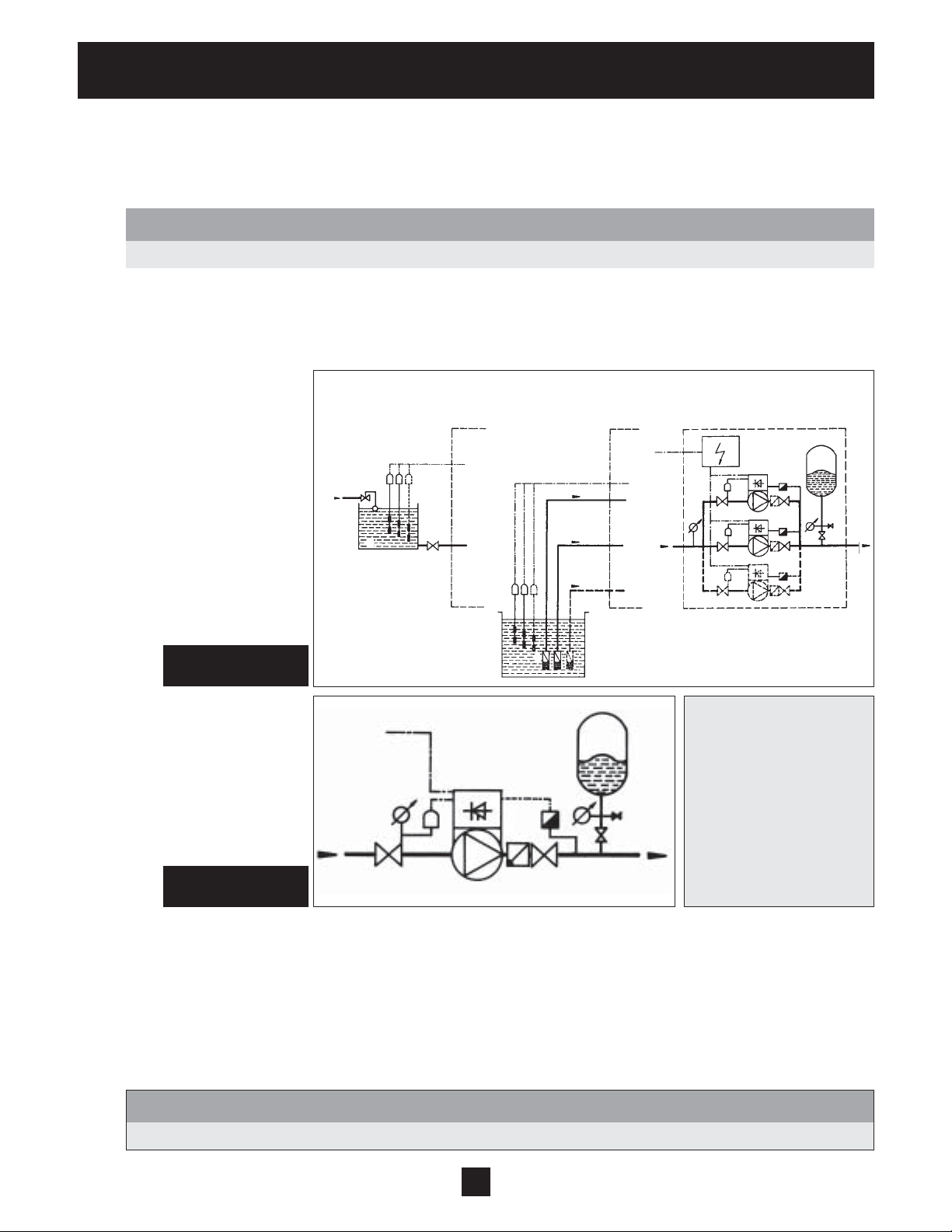
The following diagrams show typical single pump and multi-pump systems using the AQUAVAR Model 56 Controller.
Connection can be made directly to a water supply or water can be drawn from a supply tank or well. In the case of
supply tanks and wells, level switches, (item 10) can be used to shut down the pumps when water is low. In the
direct connection, a pressure switch on the suction side (item 8) can be used.
Diagram 1
Multiple Pump Layout
Diagram 2
Single Pump Layout
Indirect connection
via supply tank
10
11
9
8
4
Suction out of a well Direct connection
3
8
4
9
8
4
10
6
2
14
1
5
9
4
8
4
1 Pump with AQUAVAR Model 56
Controller
2 Diaphragm tank
3 Distribution panel
4 Gate valves
5 Check valves
6 Foot valves
8 Incoming pressure control
9 Pressure gauges
10 Level switches
11 Supply tank
14 Pressure transmitter
2
14
4
1
5
9
14
4
1
5
14
4
1
5
A diaphragm pressure tank is used on the discharge side of the pump or pumps to maintain pressure in the line when
there is no demand. This will keep the pumps from continuing to run. With the AQUAVAR Model 56 Controller, it is not
necessary to have a large tank for supply purposes. In selecting a tank, make sure it can withstand system pressure.
The tank should have a capacity of about 10% of the maximum single pump flow rate in gpm. Pre-charge the tank to
the following:
PSI Set Pressure 15 30 45 60 75 90 105 120 135 150
PSI Tank Pre-charge 12 21 37 52 64 77 95 110 125 138
Note
Closed loop circulator systems may not require a pressure tank.
1
Page 7
! Safety Instructions
Important: Read all safety information prior to installation of the
AQUA V AR Model 56 Controller.
Note
This is a SAFETY ALERT SYMBOL. When you see this symbol on the pump or in the manual, look
for one of the following signal words and be alert to the potential for personal injury or property
damage.
DANGER
WARNING
CAUTION
NOTICE Indicates special instructions which are very important and must be followed.
1. This manual is intended to assist in the installation, operation, and repair of the AQUAVAR Model 56
Controller and must be kept with the AQUAVAR Model 56 Controller.
Warns of hazards that WILL cause serious personal injury, death, or major property
damage.
Warns of hazards that CAN cause serious personal injury, death, or major property
damage.
Warns of hazards that CAN cause personal injury or property damage.
Note
All operating instructions must be read, understood, and followed by the operating personnel. Goulds
Pumps accepts no liability for damages or operating disorders which are the result ofnon-compliance
with the operating instructions.
2. To avoid serious or fatal personnel injury or major property damage, read and follow all safety instructions
in this manual.
2
Page 8

! Safety Instructions
Safety Instructions
3. Installation and maintenance MUST be performed by properly trained and qualified personnel.
4. Review all instructions and warnings prior to performing any work on the AQUAVAR Model 56 Controller.
5. Any safety decals MUST be left on the AQUAVAR Model 56 Controller unit and pump.
Note
Inspect AQUA VAR Model 56 Controller for any damage after unpacking from shipping crates. Report
any damage immediately to the carrier or distributor/dealer immediately.
6. In addition to instructions contained in this manual, you must meet any local safety, electrical, or plumbing
codes and requirements. Installation, maintenance, or repair work must only be carried out by trained,
skilled, and qualified personnel.
7. The AQUAVAR Model 56 Controller drive head must be disconnected from the main power supply
before attempting any operation in the electrical or mechanical part of the system.
Note
When in operation, the motor can be stopped, but power remains at the drive head. The motor
and pump could start unexpectedly and produce serious injury. When the AQU AVAR Model 56
Controller drive head is connected to the main power supply, the inverter power supply and master
control unit are also connected to the power supply.
WARNING
Hazardous voltage
can shock, burn or
cause death.
WARNING!
FAILURE TO DISCONNECT ELECTRICAL POWER BEFORE ATTEMPTING ANY MAINTENANCE
CAN CAUSE SHOCK, BURNS, OR DEATH.
3
Page 9
Installation Procedures
Electrical Connections continued
Step 1 - Identify Materials
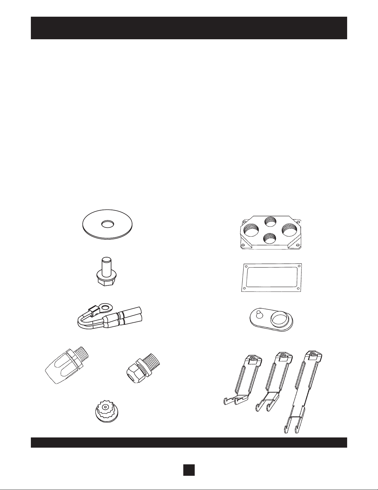
The following materials are provided with the AQUA VAR Model 56 Controller. Please familiarize yourself with
each prior to installation.
PART QUANTITY P ART QUANTITY
1) AQUA VAR Model 56 Controller 1 6) 3/8" NPT Cord Grip 2
2) Washer (AV 1.1) 1 7) 3/8" NPT Plug 1
3) Mounting Bolt (AV 1.1) 1 8) Conduit Plate (two types) 1
4) Thermistor 1 9) Gasket 1
5) 1/2" NPT Liquid Tight Connector 3 10) Cover 1
11) Mounting Clamps (AV 1.15, 2.2) 4
2
8
3
9
4
5
6
10
Diagram 3
7
4
11
Page 10

Installation Procedures
Step 2 – Mounting the AQUA V AR Model 56 Controller
1) The AQUA V AR Model 56 Controller drive
head is supplied with electrical connectors
and mounting hardware.
• Remove the motor fan cover from your
three phase TEFC motor by removing the
fan cover screws.
•Obtain the fan cover (5) and the AQUAV AR
Model 56 Controller (1) and attach them
together with the mounting bolt (4) and
washer (3).
•Use the fan cover screws to mount the fan
cover/AQUA V AR Model 56 Controller
combination to the motor.
Diagram 4
(AV 1.1 style)
AQUAVAR Model 56 Controller Dimensions
(Weight = 4.3 lbs.)
155 mm
120 mm
Diagram 5
65 mm
5
Page 11
Installation Procedures
Step 2 – Mounting the AQUA VAR Model 56 Controller
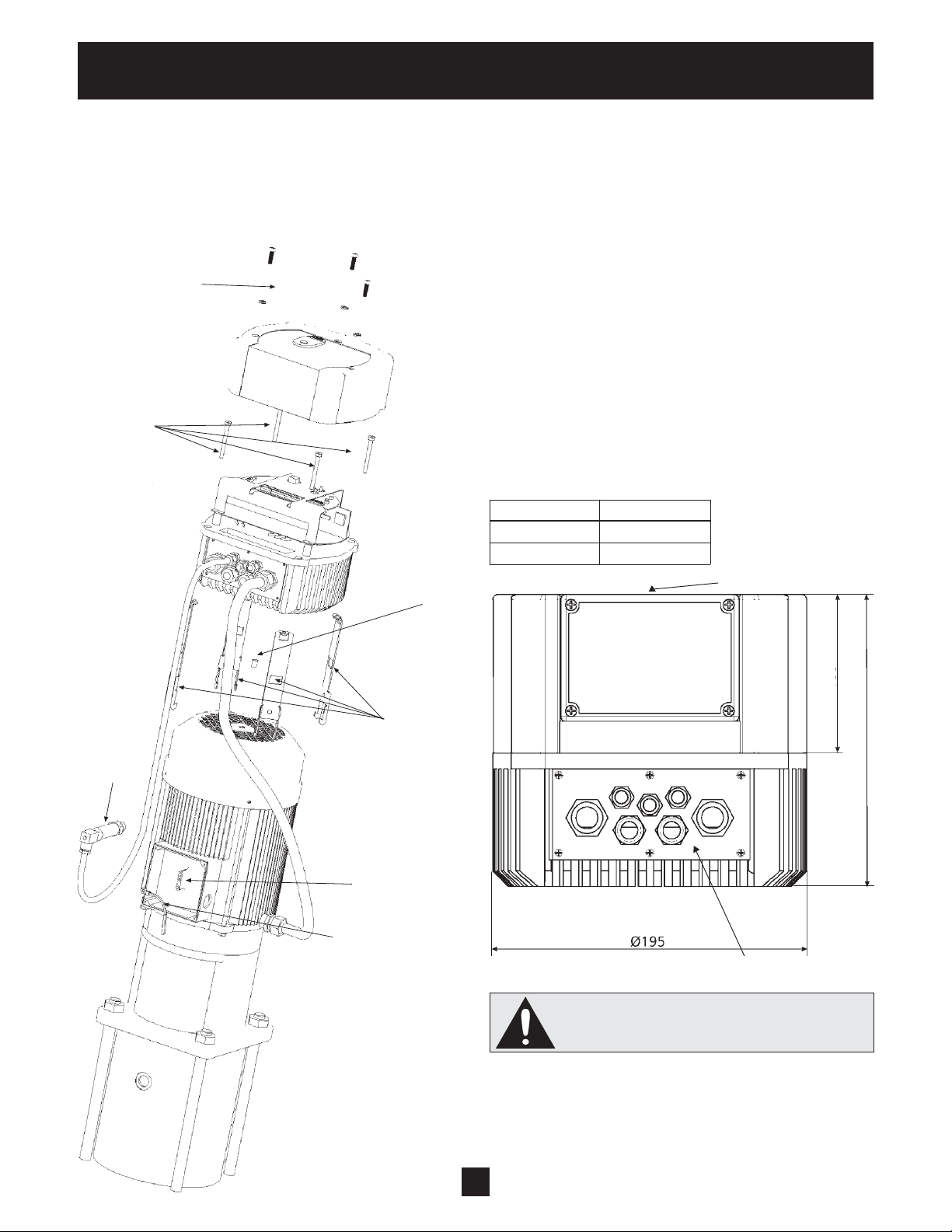
2) Mounting:
• Remove the 3 screws from the AQUA VAR
cover.
•Place the center bit in the AQUAV AR heat
sink.
•Place the AQUAV AR on the motor.
• Hang the 4 clamps by the motor fan cover
and mount with the 4 screws to the
AQUA V AR.
• Replace the AQUA VAR cover with the
3 screws.
Type Weight (kg)
AV 1.15 4.70
AV 1.2 4.70
4 screw
M5x50
continued
Gasket
Center bit
(AV 1.15, AV 2.2 style)
Closing cap
Transducer
4 mounting
clamps
Connection
motor
conduit box
Thermistor
70
155
Cable entries
Don't forget the gaskets for the 3 screws.
Ensure that there is no water on the unit
before you open the cover.
6
Page 12

Installation Procedures
Electrical Connections
WARNING
WARNING!
FAILURE TO DISCONNECT AND LOCKOUT ELECTRICAL POWER AND WAIT FIVE MINUTESFOR
CAPACITOR DISCHARGE BEFORE SERVICING AQUAVAR MODEL 56 CONTROLLER CAN CAUSE
Hazardous voltage
can shock, burn or
cause death.
SHOCK, BURNS, OR DEATH.
Note
Installation and maintenance must only be performed by properly trained and qualified personnel
equipped with the proper tools.
WARNING
Hazardous voltage
can shock, burn or
cause death.
WARNING!
INSTALL, GROUND, AND WIRE ACCORDING TO LOCAL AND NATIONAL ELECTRICAL
CODE REQUIREMENTS.
INSTALL AN ALL LEG DISCONNECT SWITCH NEAR THE MOTOR.
DISCONNECT AND LOCKOUT ELECTRICAL POWER BEFORE INSTALLING OR SERVICING.
ELECTRICAL SUPPLY MUST MATCH PUMP’S AND AQUAVAR MODEL 56 CONTROLLER NAMEPLATE
SPECIFICATIONS. INCORRECT VOLTAGE OR WIRING CAN CAUSE FIRE DAMAGE, AND VOIDS
WARRANTY.
MOTORS WITH AUTOMATIC THERMAL PROTECTION MAY OPEN THEIR ELECTRICAL CIRCUIT
WHEN A THERMAL OVERLOAD EXISTS. THIS CAN CAUSE THE MOTOR TO START UNEXPECTEDLY
AND WITHOUT WARNING.
7
Page 13

Installation Procedures
Step 3 – Wiring the AQUA V AR Model 56 Controller to the motor
(Parts in the electrical fittings package will be
required for this procedure). Refer to diagrams 6 and
7 before proceeding.
1) Remove the 3 screws holding the top of the
AQUA V AR Model 56 Controller. Carefully lift
off the top, disconnect the groundwire and set
aside.
2) Motor Lead Connections: Locate the
terminals U, V, W and GRD #1 inside the
AQUA V AR Model 56 Controller. Connect
wires to the terminals and route the cable as
shown on diagram 7.
3) Connections in Conduit Box: The free end of
the motor cable should now be routed
through the strain relief on the conduit box.
Connect the motor leads using the motor
nameplate as reference.
TERMINALS
FOR RS485
MOTOR CONNECTIONS
X2
X3
Diagram 6
U V W
GRD #2 #1
NO
12
slave pump
CC
11
NC
10
9
motor thermistor
8
7
low water
6
5
external on/off R, 10 kohm, 5 volt DC
4
+5 V ub (red)
3
actual value signal 0.5-4.5 VDC, 50 ohm load resistance (white)
2
shield (black)
1
+ 5V
4
GND
3
RS-485
SIO +
2
SIO -
1
CONTROL TERMINALS
MAIN SUPPLY
L2
L1
Place the thermistor terminal in the conduit
box and fasten so that the sensor will contact
the motor shell. Connect the thermistor with
2 wires routed to locations X2 #9 and X2 #8.
4) Pressure Transducer Installation and
Wiring: Locate the pressure transducer and
cable. The threaded end of the transducer is
1
⁄4" NPT. Install the transducer in the
a
discharge pipe on the downstream side of
the check valve and connect the cable.
Now select one of the remaining holes in
the plate on the AQUA V AR Model 56
Controller heat sink. Route the cable through
the o-ring and fasten. Cut to length and
connect to locations X2 #1, X2 #2, X2 #3.
See diagram 6 for reference.
Diagram 7
8
Page 14

Installation Procedures
Electrical Connections continued
5) Input Power Cable Installation: The main
power cable is connected to GRD #2, L1, L2
for 230 V olt single phase.
•Route the cable through the strain relief per
diagram #7, cut to length and connect.
•See Appendix B for protection requirements.
6) For Multi-Pump Systems: Use a three core
shielded cable to connect terminals X3/1,
X3/2 and X3/3 between the AQUA VAR Model 56
Controller units. These are the RS-485 interface
connections. (See diagram 6 and 8). Shielding
may be grounded on terminal X3/3.
7) Low W ater Switch: Used to indicate low
water, connect to terminals X2/6 and X2/7.
Refer to diagram 6. Jump terminals if not used.
8) External On/Off: Used to turn the AQUA VAR
Model 56 Controller on/off from an external panel
or controller, connect to X2/5 and X2/4. Refer
to diagram 6. Jump terminals if not used.
9) Relay: This connection may be used to turn
on/off a full speed slave pump or an external
run or error indicator. Wire the relay to the
switch controlling the device selected.
(X2/10, X2/11, and X2/12)
Motor
connections
Terminals of
the RS485
interface
Main supply
connections
Motor
connections
Control
terminals
AV 1.1 AV 1.15, 1.2
9
Page 15

Installation Procedures
Pump Priming
Refer to your pump operation manual for instructions on pump priming.
Run Test
WARNING
DO NOT APPL Y POWER TO THE AQU AVAR MODEL 56 CONTROLLER OR PUMP UNTIL
ELECTRICAL CONNECTIONS HAVE BEEN REVIEWED BY A QUALIFIED ELECTRICIAN AND MEET
ALL APPLICABLE STATE AND LOCAL REQUIREMENTS.
Instructions
1) Check all wiring. All motors used with the
AQUA V AR Model 56 Controller are three
phase TEFC (a wall mounted version permits
the use of other enclosures). Y ou will need to
check the direction of rotation of the motor
shaft. If you have followed all of the previous
steps carefully, you should now be ready to
apply power to the AQUA V AR Model 56
Controller unit.
2) Close discharge valve. Make sure the
discharge valve is closed. Apply power to the
AQUA V AR Model 56 Controller.
3) The next step is to apply power to the AQUA V AR
Model 56 Controller and check for proper rotation
of the motor. The first start up of the AQUAV AR
Model 56 Controller should be done with the
external programming device. If you operate the
AQUA V AR Model 56 Controller without the
programming device, the following parameters
have to be set in the submenu (see operation in
the main menu).
Screen
—
—
NO AUTOSTART – DISABLE INVERTER
◆ Change pressure: ENABLED
◆ Autostart: ENABLED
The AQUA V AR Model 56 Controller is
delivered with these settings as standard.
Change Pressure without Remote Control
1) Start the pump with the push button on
the front plate of the AQUA V AR Model 56
Controller.
2) Then press the and buttons together
for more than 3 seconds.
▼
▼
▼
10
Page 16

Installation Procedures
Change Pressure without Remote Control (continued)
3) The LED color changes to orange.
4) Now you could change the pressure with the
▼
and buttons. The set pressure is read
off a gauge on the pump discharge.
5) If there is no change to the setting for more than
5 seconds, the AQUA VAR Model 56 Controller
returns to normal operation automatically, and
the new required pressure is stored.
6) The pump can only be STARTED with the
button or STOPPED with the button.
Both buttons are on the front plate of the
AQUA VAR Model 56 Controller.
If the direction of rotation was not correct,
remove all power from the AQUA VAR Model 56
Controller and wait 5 minutes. Open the motor
conduit box and exchange any two of the three
motor leads. Close the conduit box.
Repeat the above steps.
▼
▼
▼
LED description
Orange Solid – The external programming device is connected. Required pressure can be
changed with the buttons and .
Orange Fast Flashing – Connected remote control and the pump is running.
Orange Slow Flashing – Connected remote control the inverter is on and the pump is stopped
because required pressure is reached.
Green Solid – Motor is not running. (Open external stop with terminals X2/4; X2/5 or the item
is stopped with the button on the front plate.
Green Slow Flashing – Inverter is active, but the motor has stopped.
Green Fast Flashing – Motor is running.
Red Solid – Error.
Red Flashing – Fatal error (AQUAVAR Model 56 Controller has to be disconnected from the power
supply).
➔
➔
▼
General Instructions for working with the external programming
device.
With the and ➔ keys you can select the different parameter windows in the menu. To enter a submenu
press the button. To leave the submenu, press and hold the ➔ or the for more than 3 seconds.
➔
➔
➔
Each change in the settings are stored after leaving this parameter window with the or ➔. During
saving “SAVE PARAMETER” is shown on the display of the programming device for a short time.
11
➔
Page 17

Installation Procedures
Connecting the External Programming Device to the
AQUA V AR Model 56 Controller
After connection of the AQUAVAR Model 56 Controller to the power supply and attachment of the external
programming device, one of two different messages will be shown:
1) If the AUTOCONNECTION is disabled
(standard) you see:
•This message is shown, when the Remote
Control is first connected. At this time the
AQUA VAR Model 56 Controller searches for
an available address.
•If address 01 is available, the display changes
to:
The actual pump address is shown.
•If the actual pump address 01 is not available
the display does not change and you will see
again:
Then you could change the address with
➔
and and confirm the selected address
with ➔.
When you are connected to a system with more than one pump, connected together over the
interface, you can select with and , the address of the pump you want to talk to and confirm
the selected address with ➔. Status information is shown as follows:
P1: Masterpump
P2: Slavepump
P3: Slavepump
➔
➔
➔
ADDRESS 01
LOST
ADDRESS 01
DETECTED
ADDRESS 01
LOST
P4: Slavepump
P: Number is not used
Hold: Pump stops through the pressure transmitter
Run: Pump runs
Stop: Pump stops through the lead pump
Disabled: Pump stops through the stop button or the terminal block
Error: Pump stops through an error
12
Page 18

Programming
Press ➔ on the controller and you enter the INVERTERMENU
2) If the AUTOCONNECTION is enabled, the
following message is shown:
•This message is shown during the
connection, when AUTOCONNECTING is
enabled. In this time the AQUA V AR Model 56
Controller searches for the given or entered
address.
•Then the display changes to the first display .
The actual input value (%) and the actual
output frequency (Hz) are displayed.
SCAN
CONNECTION
PRESS X.X%
SPEED X.X Hz
I. The Main Menu – Setting Single Pump Constant P ressure
(Flowchart #1)
On the first startup of the Aquavar Model 56 Controller with the external programmer the “Change
Pressure” and “Autostart” are enabled. After connecting, the display on the remote control reads.
This message is shown when the Remote
Control is attached to the AQUA VAR Model 56
Controller.
SCAN CONNECTION
After a few seconds the display changes
automatically to:
This shows the actual values for pressure and
speed. Press ➔ on the controller to change to:
➔
To change the pressure use the and
buttons. If you have changed the value you will
get the message “SAVE PARAMETER” for a
short time. Press ➔ on the controller to return
to the actual value display.
➔
PRESSURE X.X psi
SPEED X.X Hz
PRESSURE XX.X psi
II. Single Pump – P ump Protection (Flowchart #2)
The AQUA V AR Model 56 Controller has the ability to protect the pump by shutting it off in low/no suction or
run out conditions.
Note
Low/no suction protection depends on the installation of a suction line pressure switch, or float switch
for a tank. This switch is connected to the AQUA VAR Model 56 Controller as described earlier in the
Electrical Installation section. The cut off setting for this switch should be the maximum NPSH required
by the pump.
13
Page 19

Programming
To set run out protection:
Note
Run out protection occurs if the pump is running at full speed, and the set pressure cannot be
recorded after a set period of time. To set run out protection you need to enter the amount of
pressure drop and the time delay.
Instructions
1) Password The password protection prevents
untrained personnel from accidentally changing
the base setting.
• From the parameter screen on the main menu
press the arrow until the display changes to:
➔
PASSWORD
0000
2) Press the arrow until you reach the number
➔
0066.
3) Press the ➔ arrow repeatedly until you reach:
➔
4) Press the arrow once and you will reach:
5) By pressing the arrow . Enter the pressure
➔
setting (in psi) at which you want the pump to
shutoff. Typically a setting of 3 to 5 psi less
than the standard pressure setting would be
entered.
6) Now press the ➔ arrow and you will reach:
7) By pressing the arrow you will be entering
➔
the amount of time (in seconds) that the pump
will run at the pressure setting programmed
into the conveyor limit before it automatically
shuts off. Returning to normal operation:
8) Hold the ➔ arrow down for 3 seconds and you
will be returned to:
PASSWORD
0066
SUBMENU
ERROR
CONVEYOR LIMIT
0.0 PSI
CONVEYOR LIMIT
25 PSI
ERROR DELAY
0S
ERROR DELAY
5S
SUBMENU
ERROR
9) Hold the ➔ arrow down again for 3 seconds
and you will be returned to: The Main Menu.
PRESSURE 00 PSI
SPEED 00HZ
14
Page 20

Submenu
Address
Entry
Submenu
Configuration
Address
Change
A –
Connecting
Enabled
Software:
Software:
VOG
Submenu
Parameter
Password
0066
Change Pres.
Enabled
Auto Start
Enabled
Mode
Controller
Reg. Mode
Normal
Submenu
Inverter
Submenu
Controller
Submenu
Multicontroller
Submenu
Relais
Submenu
Sensor
Submenu
Testrun
Submenu
Error
Set Password
0000
Defaults
Submenu
Diagnosis
Password
OK
Software
CP-VOG: 001
3rd Error
XXX
2nd Error
XXX
Last Error
XXX
Pump-
Address
2
Pump
Runtime
00000 h
Conveyor
Limit
0.0 psi
Error Delay
10 s
Start Test Run
(Inc + Dec)
Time Test –
Run
100 h
Test
Frequency
30.0 Hz
Boost Test –
Run
Sensormax –
adj
0.5-4.5 V
Sensor Adust
Out of range
Relais
Config.
Simple
Multicnt.
Actu. Value
Dec
4.0 psi
Slave-on
Limit
48.0 Hz
Enable Seq.
Ctl
58 Hz
Window
15%
Max. Frequ.
60.0 Hz
Min. Frequ.
0.0 Hz
Hysterisis
80%
Accel. High
4 s
Boost
5.0%
Decel. High
4 s
Lift Intensity
0.0%
Lift Frequency
30.0 Hz
Decel. Low
70 s
Accel. Low
70 s
Config. F
min
F - > 0
Switch
Interval
12 Hours
Actu. Value
Inc.
6.0 psi
Slave-Off
Limit
0 Hz
Dimension
Unit (psi)
Address 01
Detected
Press x.x psi
Speed x.x Hz
Pressure
xx.x psi
Programming
Single Pump – Constant P ressure (Flowchart #1)
15
Page 21

Submenu
Address
Entry
Address 01
Detected
Submenu
Configuration
Address
Change
A –
Connecting
Enabled
Software:
Software:
VOG
Press x.x psi
Speed x.x Hz
Pressure
xx.x psi
Submenu
Parameter
Password
0066
Change Pres.
Enabled
Auto Start
Enabled
Mode
Controller
Reg. Mode
Normal
Submenu
Inverter
Submenu
Controller
Submenu
Multicontroller
Submenu
Relais
Submenu
Sensor
Submenu
Testrun
Submenu
Error
Set Password
0000
DefaultsSubmenu
Diagnosis
Password
OK
Software
CP-VOG: 001
3rd Error
XXX
2nd Error
XXX
Last Error
XXX
Pump-
Address
2
Pump
Runtime
00000 h
Conveyor
Limit
0.0 psi
Error Delay
10 s
Start Test Run
(Inc + Dec)
Time Test –
Run
100 h
Test
Frequency
30.0 Hz
Boost Test –
Run
Sensormax –
adj
0.5-4.5 V
Sensor Adust
Out of range
Relais
Config.
Simple
Multicnt.
Actu. Value
Dec
4.0 psi
Slave-on
Limit
48.0 Hz
Enable Seq.
Ctl
58 Hz
Window
15%
Max. Frequ.
60.0 Hz
Min. Frequ.
0.0 Hz
Hysterisis
80%
Accel. High
4 s
Boost
5.0%
Decel. High
4 s
Lift Intensity
0.0%
Lift Frequency
30.0 Hz
Decel. Low
70 s
Accel. Low
70 s
Config. F
min
F - > 0
Switch
Interval
12 Hours
Actu. Value
Inc.
6.0 psi
Slave-Off
Limit
0 Hz
Dimension
Unit (psi)
Programming
Single Pump – P ump Protection (Flowchart #2)
16
Page 22

Programming
III. Single Pump – System Curve Compensation (Flowchart #3)
The AQUA V AR Model 56 Controller can
automatically compensate for system friction losses
due to increased flow . Tables are available in most
pump catalogs (including the G&L Pumps catalog)
indicating the amount of friction loss that can be
expected in various sizes of pumps at different flow
rates. Use these tables to determine the friction
loss for the pipe size you are using at your
maximum flow rate.
Diagram 8 shows a typical system curve. The system
pressure set point is shown at shut-off and the
pressure increase is shown for increasing flow .
Calculate the pressure increase required to
overcome friction loss at maximum flow as a
percent of the set point.
For example, if your required system pressure is
30 psi and it takes an additional 3 psi for friction
loss at maximum flow , the percent increase is 10%.
SET PRESSURE
0
Diagram 8
H
f = 100%
% f
% f
% f
1
0
0
2
WINDOW
LIFT INTENSITY
10% OF
SET PRESSURE VALUE
4
3
Q
17
Page 23

Programming
Entering Compensation V alues
Instructions
1) From the P arameter screen on the main menu
➔
press the arrow and the display changes to:
2) Press the arrow until you reach the number
➔
0066.
3) Press the ➔ arrow repeatedly until you reach:
➔
4) Press the arrow once and you will reach:
5) Press the ➔ arrow several times until you
reach:
6) Now press the arrow until you reach the
➔
desired “Lift Frequency”. This is the frequency
at which the pump works at the set pressure
and a flow of 0 GPM. On a 60 Hz system, there
is virtually no flow below 40 Hz.
7) Use the ➔ arrow to move to the screen:
8) Now press the arrow until you reach the
➔
desired “Lift Intensity”. This value states how
much the set value should be continually
increased until the maximum speed is reached.
PASSWORD
0000
PASSWORD
0066
SUBMENU
CONTROLLER
WINDOW
0.0%
LIFT FREQUENCY
6 Hz
LIFT FREQUENCY
40 Hz
LIFT INTENSITY
0%
LIFT INTENSITY
3%
Returning to normal operation:
9) Hold the ➔ arrow down for 3 seconds and
you will be returned to:
10)Hold the ➔ arrow down again and you will be
returned to the main menu.
SUBMENU
CONTROLLER
PRESSURE 00 PSI
SPEED 00HZ
18
Page 24

Submenu
Address
Entry
Address 01
Detected
Submenu
Configuration
Address
Change
A –
Connecting
Enabled
Software:
Software:
VOG
Press x.x psi
Speed x.x Hz
Pressure
xx.x psi
Submenu
Parameter
Password
0066
Change Pres.
Enabled
Auto Start
Enabled
Mode
Controller
Reg. Mode
Normal
Submenu
Inverter
Submenu
Controller
Submenu
Multicontroller
Submenu
Relay
Submenu
Sensor
Submenu
Testrun
Submenu
Error
Set Password
0000
DefaultsSubmenu
Diagnosis
Password
OK
Software
CP-VOG: 001
3rd Error
XXX
2nd Error
XXX
Last Error
XXX
Pump-
Address
2
Pump
Runtime
00000 h
Conveyor
Limit
0.0 psi
Error Delay
10 s
Start Test Run
(Inc + Dec)
Time Test –
Run
100 h
Test
Frequency
30.0 Hz
Boost Test –
Run
Sensormax –
adj
0.5-4.5 V
Sensor Adust
Out of range
Relay
Config.
Simple
Multicnt.
Actu. Value
Dec
4.0 psi
Slave-on
Limit
48.0 Hz
Enable Seq.
Ctl
58 Hz
Window
15%
Max. Frequ.
60.0 Hz
Min. Frequ.
0.0 Hz
Hysterisis
80%
Accel. High
4 s
Boost
5.0%
Decel. High
4 s
Lift Intensity
0.0%
Lift Frequency
30.0 Hz
Decel. Low
70 s
Accel. Low
70 s
Config. F
min
F - > 0
Switch
Interval
12 Hours
Actu. Value
Inc.
6.0 psi
Slave-Off
Limit
0 Hz
Dimension
Unit (psi)
Programming
System Curve Compensation (Flowchart #3)
19
Page 25

Programming
IV. Circulator Applications
On circulator pumps, the system curve can be automatically tracked through the use of a differential pressure
transducer. This pressure transducer reads the outgoing discharge pressure and the incoming return pressure
and compensates for differences in pressure as demand and speed increase. Programming is the same as just
covered for the single transducer version. Data on the differential pressure transducer can be found in
Appendix A.
V. Multiple Pump Constant Pressure System Curve Compensation
(Flowchart #4)
When two, three or four AQUA V AR Model 56 Controller controlled pumps are connected in a system, they
can be programmed to work together to maintain system pressure up to the maximum flow rate of all the
pumps combined. As the first pump reaches its maximum speed and flow , the second pump will
automatically turn on (and so on). In addition, the sequence of the pump that will run first (lead pump) can be
automatically varied to reduce premature wear on any one pump in the system.
1) Refer to the section “The Main Menu - Setting One Pump Constant Pressure”. Follow the step
then continue below .
Instructions
2) From the P arameter screen on the main menu
press the arrow until the display changes to:
3) Press the arrow until you reach the number
0066
4) Press the ➔ arrow repeatedly until you reach:
5) Press the arrow and the display changes to:
Generally a slight pressure drop is allowed on the
first pump before the next is started. This allows for
brief system fluctuations without pump cycling. Once
the next pump starts, however, you will want the
system to resume its normal set pressure.
➔
➔
➔
PASSWORD
0000
PASSWORD
0066
SUBMENU
MULTICONTROLLER
ACTUAL VALUE INCREASE
0.0 PSI
20
Page 26

Programming
H
Q
7
6
5
4
3
2
1
0
PUMP 1 PUMP 1 +
PUMP 2
PUMP 1 +
PUMP 2 +
PUMP 3
2
1
3
ACTUAL VALUE DECREASE
ACTUAL
VALUE
INCREASE
6) To do this, enter the amount of pressure drop
you will allow before the next pump starts.
Diagram 9 shows the pressure drop and
increase.
7) To increase the pressure even more to
compensate for system loss at higher flows,
enter the total of the system drop allowed
before next pump starts and the increased
pressure desired.
For example, if the pressure drop allowed is 5 psi
before the next pump starts, and the increased
pressure needed to compensate for system losses is
3 psi, you would enter 5 + 3, or 8 psi to
compensate for both system pressure drop and
compensation requirements.
➀ If increase = decrease, pressure stays constant
➁ If increase > decrease, pressure rises with lag pump
➂ If increase < decrease, pressure falls with lag pump
Diagram 9
Note
This value is cumulative. An extra 3 psi will be added to the total system pressure with each
additional pump which turns on. For example, if the initial system pressure was 50 psi, pump
two would create 53 psi, pump three would create 56 psi, and pump four would create 59 psi system
pressure.
Instructions
8) Enter the required value by pressing the
arrow .
9) Press the ➔ arrow and the display will read:
10)Press the arrow to enter the % drop before the
next pump starts. Use this value for each pump
in the Aquavar Model 56 Controller system.
11)Press the ➔ arrow to enter sequence control
and then press . This function tells the next
pump when the preceding pump has reached
its maximum speed.
Notes: In most North American applications, this
would be set for 60 Hz. If you are using a 50 Hz
system, reset the display for 50 Hz.
Example Curve
➔
➔
➔
ACTUAL VALUE INCREASE
3.0 PSI
ACTUAL VALUE DECREASE
0.0 PSI
ACTUAL VALUE DECREASE
2.0 PSI
ENABLE SEQUENCE CONTROL
0 Hz
ENABLE SEQUENCE CONTROL
60 Hz
21
Page 27

Programming
12)Press the ➔ arrow to display... then press the
arrow to set the amount of time before the
➔
“lead” pump switches over to the next pump
on the screen.
13) In this section you will give the pump an
address number. Generally , the first pump
programmed will be number 1, the second will
be number 2, and so on. The purpose of this is
to help the Aquavar Model 56 Controller
sequence the start and stop activity of the
pumps in the system including the selection of
the lead and lag pumps (see Flowchart #5).
SWITCH INTERVAL
0 HOURS
SWITCH INTERVAL
12 HOURS
From the main menu press and hold the ➔ for
3 seconds and you will reach the address
detected screen.
Press the arrow twice and you will reach
➔
the submenu address screen.
Press the arrow and the address change
▼
will appear.
00 – >> 0001 – >> 00
01 01
02 02
03 03
04 04
Addresses from 01 to 04 and also 00 can be
set in the parameter. T o change the address it
is not necessary to cut the interface connection
to other AQUA V AR Model 56 Controllers.
On the left side is the address of the “LEAD”
AQUA V AR Model 56 Controller. On the right side
you can select the address of the AQUA V AR
Model 56 Controller by pressing the or arrows.
➔
➔
PRESSURE 00 PSI
SPEED 00 HZ
ADDRESS 01
DETECTED
SUBMENU
ADDRESS
ADDRESS CHANGE
* 01 – – >> 00
00 ––––> 01*
To change between the left and right side,
➔
press ➔ or .
To leave the submenu press the ➔ arrow for
3 seconds.
PRESSURE 00 PSI
SPEED 00 HZ
22
Page 28

Programming
VI. Slave Pump Operation (Flowchart #6)
1) From the P arameter screen on the main menu
➔
press the arrow and the display changes to:
2) Press the arrow until you reach the number
➔
0066.
3) Press the ➔ repeatedly until you reach:
➔
4) Press the arrow and you will reach:
5) Press the ➔ and you will see:
• This is the frequency the slave pump will turn
on and run at maximum speed. Adjust with
➔
and until you reach the desired setting.
Generally this is at 60 Hz.
6) Press the ➔ arrow until you reach:
• This is the frequency the slave pump will turn
off. Adjust with and until you reach the
➔
➔
desired setting. Generally this is at 40 Hz.
➔
PASSWORD
0000
PASSWORD
0066
SUBMENU
RELAY
RELAY
CONFIGURATION
SLAVE ON
LIMIT
SLAVE OFF
LIMIT
23
Page 29

Submenu
Address
Entry
Address 01
Detected
Submenu
Configuration
Address
Change
A –
Connecting
Enabled
Software:
Software:
VOG
Press x.x psi
Speed x.x Hz
Pressure
xx.x psi
Submenu
Parameter
Password
0066
Change Pres.
Enabled
Auto Start
Enabled
Mode
Controller
Reg. Mode
Normal
Submenu
Inverter
Submenu
Controller
Submenu
Multicontroller
Submenu
Relay
Submenu
Sensor
Submenu
Testrun
Submenu
Error
Set Password
0000
DefaultsSubmenu
Diagnosis
Password
OK
Software
CP-VOG: 002
3rd Error
XXX
2nd Error
XXX
Last Error
XXX
Pump-
Address
2
Pump
Runtime
00000 h
Conveyor
Limit
0.0 psi
Error Delay
10 s
Start Test Run
(Inc + Dec)
Time Test –
Run
100 h
Test
Frequency
30.0 Hz
Boost Test –
Run
Sensormax –
adj
0.5-4.5 V
Sensor Adust
Out of range
Relay
Config.
Simple
Multicnt.
Actu. Value
Dec
4.0 psi
Slave-on
Limit
48.0 Hz
Enable Seq.
Ctl
Window
15%
Max. Frequ.
60.0 Hz
Min. Frequ.
0.0 Hz
Hysterisis
80%
Accel. High
4 s
Boost
5.0%
Decel. High
4 s
Lift Intensity
0.0%
Lift Frequency
30.0 Hz
Decel. Low
70 s
Accel. Low
70 s
Config. F
min
F - > 0
Switch
Interval
12 Hours
Actu. Value
Inc.
6.0 psi
Slave-Off
Limit
0 Hz
Dimension
Unit (psi)
Programming
Multiple Pump – Constant P ressure (Flowchart #4)
24
Page 30

Submenu
Address
Entry
Address 01
Detected
Submenu
Configuration
Address
Change
A –
Connecting
Enabled
Software:
Software:
VOG
Press x.x psi
Speed x.x Hz
Pressure
xx.x psi
Password
0066
Change Pres.
Enabled
Auto Start
Enabled
Mode
Controller
Reg. Mode
Normal
Submenu
Inverter
Submenu
Controller
Submenu
Multicontroller
Submenu
Relay
Submenu
Sensor
Submenu
Testrun
Submenu
Error
Set Password
0000
DefaultsSubmenu
Diagnosis
Password
OK
Software
CP-VOG: 001
3rd Error
XXX
2nd Error
XXX
Last Error
XXX
Pump-
Address
2
Pump
Runtime
00000 h
Conveyor
Limit
0.0 psi
Error Delay
10 s
Start Test Run
(Inc + Dec)
Time Test –
Run
100 h
Test
Frequency
30.0 Hz
Boost Test –
Run
Sensormax –
adj
0.5-4.5 V
Sensor Adust
Out of range
Relay
Config.
Simple
Multicnt.
Actu. Value
Dec
4.0 psi
Slave-on
Limit
48.0 Hz
Enable Seq.
Ctl
Window
15%
Max. Frequ.
60.0 Hz
Min. Frequ.
0.0 Hz
Hysterisis
80%
Accel. High
4 s
Boost
5.0%
Decel. High
4 s
Lift Intensity
0.0%
Lift Frequency
30.0 Hz
Decel. Low
70 s
Accel. Low
70 s
Config. F
min
F - > 0
Switch
Interval
12 Hours
Actu. Value
Inc.
6.0 psi
Slave-Off
Limit
0 Hz
Dimension
Unit (psi)
Submenu
Parameter
Programming
Address Change (Flowchart #5)
25
Page 31

Programming
Submenu
Address
Entry
Address 01
Detected
Submenu
Configuration
Address
Change
A –
Connecting
Enabled
Software:
Software:
VOG
Press x.x psi
Speed x.x Hz
Pressure
xx.x psi
Password
0066
Change Pres.
Enabled
Auto Start
Enabled
Mode
Controller
Reg. Mode
Normal
Submenu
Inverter
Submenu
Controller
Submenu
Multicontroller
Submenu
Relay
Submenu
Sensor
Submenu
Testrun
Submenu
Error
Set Password
0000
DefaultsSubmenu
Diagnosis
Password
OK
Software
CP-VOG: 001
3rd Error
XXX
2nd Error
XXX
Last Error
XXX
Pump-
Address
2
Pump
Runtime
00000 h
Conveyor
Limit
0.0 psi
Error Delay
10 s
Start Test Run
(Inc + Dec)
Time Test –
Run
100 h
Test
Frequency
30.0 Hz
Boost Test –
Run
Sensormax –
adj
0.5-4.5 V
Sensor Adust
Out of range
Relay
Config.
Simple
Multicnt.
Actu. Value
Dec
4.0 psi
Slave-on
Limit
48.0 Hz
Enable Seq.
Ctl
Window
15%
Max. Frequ.
60.0 Hz
Min. Frequ.
0.0 Hz
Hysterisis
80%
Accel. High
4 s
Boost
5.0%
Decel. High
4 s
Lift Intensity
0.0%
Lift Frequency
30.0 Hz
Decel. Low
70 s
Accel. Low
70 s
Config. F
min
F - > 0
Switch
Interval
12 Hours
Actu. Value
Inc.
6.0 psi
Slave-Off
Limit
0 Hz
Dimension
Unit (psi)
Submenu
Parameter
Slave Pump (Flowchart #6)
26
Page 32

Operator Custom Features and Displays
Settings at the Inverter Menu
This message is shown during the connecting, when
autoconnecting is enabled.
The actual input value (%) and the actual output
frequency (Hz) are displayed.
➔
Set required pressure with the buttons and .
➔
➔
To enter the submenu “Parameter”, press button.
Settings at the Submenu-Parameter
IMPORT ANT
Before entering the secondary menu these instructions must be read carefully to prevent incorrect
settings which will cause malfunction.
After entering the “Submenu-P arameter” the display
will change to:
➔
Set ‘Password 0066’ by pressing and
Confirm by resetting ➔ and the first window of the
submenu is shown
Pressure Change You can decide between and
➔
(Enabled or Disabled). If the pressure setting
is enabled, you can change the pressure on the
AQUA VAR Model 56 Controller head with decrease
and increase.
Auto Start Y ou can select between Disabled
➔
and Enabled. Auto start Enabled means that
the pump starts again automatically after an
interruption of the power supply (power
failure). If Auto start Disabled is set, the pumphas to
be restarted manually after a power
failure, by pressing and .
➔
➔
➔
➔
➔
SCAN
CONNECTION
PRESS X.X PSI
SPEED X.X HZ
PRESSURE
XX.X PSI
PARAMETER
PASSWORD
0000
PASSWORD
0066
CHANGE PRESSURE
ENABLED
CHANGE PRESSURE
ENABLED
AUTO START
ENABLED
27
Page 33

Operator Custom Features and Displays
Mode Select with buttons and between:
➔
Multicontroller ➔ sequence control for max. 4
pumps. Controller ➔ pressure control for a
single pump. Actuator ➔ external frequency
setting. If only one AQUA V AR Model 56 Controller
pump is in operation, set Controller.
If more than one AQUA V AR Model 56 Controller
pumps are working together via the RS485-interface,
the Multi-controller must be selected.
The application Actuator is only used if you
have an external controller and the AQUA V AR
Model 56 Controller works like a standard
frequency converter (external frequency signal
0,5-4,5 VDC to the terminals X2/1 and 2).
Control Response Normal Speed is increased
with falling actual value signals (e.g.: Control at
constant output pressure). Inverse Speed is
reduced with falling actual value signal,
(e.g.: Control from falling suction pressure or at
constant level).
➔
MODE
CONTROLLER
REGULATION MODE
NORMAL
Dimension Unit Here you could choose your
favorite dimension ( or ). psi, Bar, or %.
Submenu Inverter To enter this menu you have
➔
➔
➔
to press the key, to leave the menu, press
the ➔ key longer than 3 sec.
Maximum Frequency P ossible setting
between min. 40 and max. 60 Hz. Settings of
10% above nominal frequency cause 33%
more power consumption!
Minimum Frequency Here you can set
the minimum frequency. ATTENTION: If f
min > 0
is set, the pump will not stop in the
normal mode. It will keep running with the set
minimum frequency!! Possibility of
overheating of the Pump!!!
DIMENSION UNIT
PSI
SUBMENU
INVERTER
MAX. FREQUENCY
60 Hz
MIN. FREQUENCY
0.0 Hz
28
Page 34

Operator Custom Features and Displays
Boost The stated value determines the
course of the V/f-curve. Setting of the motor
starting voltage in % of rated voltage. Settings
of 0 – 25% of maximum output voltage are
possible. However, care should be taken that
settings are kept as low as possible so that the
motor does not become thermally overloaded.
BOOST
Operation of the minimum frequency
If you have selected F –> 0 the frequency will
go down to the selected minimum frequency. Then
the inverter will run for the selected time, after this
time the AQUA VAR Model 56 Controller will
automatically stop.
With the selection F –> F
min you can not run the
pump below the set minimum frequency. In the
controller actuator and multicontroller mode
the pump will never run below the set
minimum frequency (the pump will only stop
with the external on/off terminals or in case of
a failure).
min Time After running the pump for this
F
selected time, the pump will stop, if parameter
12.6.5 is set on F => 0.
To enter or leave the submenu press the ➔ key longer than 3 seconds.
Submenu Controller To enter this menu you
➔
have to press the key, to leave the menu,
press and hold the ➔ key longer than three sec.
CONFIG. Fmin
F ➔ Fmin
Fmin Time
5 s
SUBMENU
CONTROLLER
Window – % This value indicates the max.
variation of the outgoing pressure
(ref. Ramp window). P ossible setting: between
0% – 100% of required pressure.
WINDOW
10%
29
Page 35

Operator Custom Features and Displays
Ramp Hysteresis Level Where the fast
ramp changes to the slow ramp. Possible
setting: between 0% – 100% of the window .
Fast Acceleration T ime T ime setting at
Ramp 1, 2, 3, or 4 will influence the control ofthe
pump and MUST NOT BE CHANGED for
normal operation. Possible setting for each
ramp 0,05 – 1000 sec. Excessively fast running
time may overload the inverter. Excessively
slow running up time may cause a break down
of the outgoing pressure.
Fast Deceleration T ime Excessively fast
running down time tends to cause oscillation
or hunting or can cause an error
(OVERVOLTAGE) during slow down of the
pump. Excessively slow running down time
tends to generate over pressure.
Slow Acceleration Time Too slow of a
running up time during variation of demand can
cause the outgoing pressure to break. Too
fast of a running up time may lead to over
oscillation and/or overload of the inverter.
HYSTERISIS
80%
ACCEL. HIGH
4 SEC.
DECEL. HIGH
4 SEC.
ACCEL. LOW
70 SEC.
Slow Deceleration Time Too fast a setting leads
to oscillation. Too slow a setting delays switching
off too much.
Ramp Window
PRESSURE
R2
R4
R3
R1
Diagram 10
R3
R3
R4
R1
R4
SET HYSTERESIS %
SET HYSTERESIS %
30
DECEL. LOW
70 SEC.
SET RATED
100%
PRESSURE
R1: SPEED RAMP FAST INCREASE
R2: SPEED RAMP FAST DECREASE
R3: SPEED RAMP SLOW INCREASE
R4: SPEED RAMP SLOW DECREASE
WINDOW
SETTING IN % OF
RATED PRESSURE
Page 36

Operator Custom Features and Displays
Compensation Frequency Control according
to a unit curve (increase of the set pressure
dependent upon the delivery rate or speed).
Adjustable between 6 Hz and the set
MAXIMUM FREQUENCY, this setting states at
which frequency the set pressure should be
increased. That is the speed at which the pump
works at the set pressure and at a flow rate of 0.
Lift-Intensity Adjustable from 0% to 100%.
This value states how much the set
value should be continually increased, till the
maximum speed (maximum volume) is
reached.
Figure: Lift-Intensity
LIFT FREQUENCY
30.0 Hz
LIFT – INTENS.
0.0%
H
f = 100%
% f
WINDOW
SET PRESSURE
Diagram 11
To leave the submenu press the key longer than 3 seconds.
Submenu Multicontroller To enter this menu
➔
➔
you have to press the key. To leave the
menu, press the ➔ key longer than 3 seconds.
% f
% f
1
0
0
0
2
LIFT INTENSITY
10% OF
SET PRESSURE VALUE
4
3
Q
SUBMENU
CONTROLLER
31
Page 37

Operator Custom Features and Displays
Lift V alue Adjustable between 0 to the
pre-selected NORMALIZE. Application
Example: 1) Pump 1 reaches f
max (maximum
ACTU. VALUE INC.
5 PSI
speed, 2) Pressure falls and reaches the
start-value of the 2nd pump (= REQUIRED
VALUE - ACTU. V AL UE DEC.), 3) Pump 2 is
switched on automatically, 4) The required
value is calculated after the start of the 2nd
pump in the following way.
New required value = REQUIRED VAL UE –
ACTU. VAL UE DEC. + ACU. V AL UE INC.
GENERAL
1) If Actual Value Increase equals Actual Value Decrease the pressure stays constant throughout
flow range.
2) If Actual Value Increase is greater than Actual Value Decrease, the pressure rises as
the lag pumps turn on and the flow increases.
3) If Actual Value Increase is less than the Actual Value Decrease, the pressure drops as the lag
pumps turn on and the flow increases.
H
7
ACTUAL
VALUE
INCREASE
6
5
4
3
2
ACTUAL VALUE DECREASE
1
0
Diagram 12
Fall Value For scaling the set pressure of
pumps 1 to 4. Adjustable from 0.0 to 100%
nd
determines the start-value of the 2
pump and
the other following pumps. (start value =
REQUIRED VAL UE - ACT. VALUE DEC.)
PUMP 1 PUMP 1 +
PUMP 2
2
1
PUMP 1 +
PUMP 2 +
PUMP 3
ACTU. VALUE DEC.
4 PSI
3
Q
32
Page 38

Operator Custom Features and Displays
Release – Follower Control Enabling of
the lag pump only when required (the
fall-value is reached) and if the lead pump has
reached the programmed frequency.
(Adjustable from 0.0 Hz to 120 Hz). If you don’t
want to start a lag pump this value has to
be set higher than the MAX. FREQUENCY.
Switch Interval For changing the lead pump and lag
pump in order to achieve even operating hours.
Adjustable between 0 and 250 hours.
To leave the submenu press the ➔ key longer than 3 seconds.
Submenu Relay To enter this menu you
➔
have to press the key, to leave the menu,
press the ➔ key longer than 3 seconds.
Relay Configuration Possible selections
with buttons and : Simple Multicnt. ➔
➔
➔
Starts a following pump (slave pump) with
constant speed.
Run Signaling ➔ Run indication over the relay
Error Signaling ➔ Fault indication over the relay
ENABLE SEQ. CTL.
45.0 Hz
SWITCH INTERVAL
12 HOURS
SUBMENU
RELAY
RELAY CONFIG.
SIMPLE MULTICNT.
Start Frequency of the Slave P ump Here
you can set the frequency of the speed
controlled AQUA V AR Model 56 Controller pump,
where the full speed slave pump starts, if “simple
multi-controller” is set in the parameter relay
configuration. In this case, the slave pump runs
with full speed and the AQUA VAR Model 56
Controller pump controls the additional demand.
Typically set at 60 Hz.
Stop Frequency of the Slave P ump Here
you can set the frequency of the speed
controlled AQUA V AR Model 56 Controller pump,
where the full speed slave pump stops, if “simple
multi-controller” is set in the parameter relay
configuration. T ypically set at 40 Hz.
To leave the submenu press the ➔ key longer than 3 seconds.
SLAVE-ON LIMIT
48,0 Hz
SLAVE-OFF LIMIT
0.0 Hz
33
Page 39

Operator Custom Features and Displays
Submenu Sensor To enter this menu you
➔
have to press the key, to leave the menu,
press the ➔ key longer than 3 seconds.
Sensor – Adjust (Zero adjustment of the
transmitter) Depressurize the system and press
➔
keys + simultaneously. After adjustment
➔
“adjusted” appears on the display. If “out of
range” is shown on the display, no adjustment
is possible.
Sensor Max-Adjust The analogue input
(terminal X2/2) is prepared for a transmitter
signal of 0,5 - 4,5VDC (= 100%). When there is
a transmitter with another signal range used,
you have to adjust this other voltage range in
this parameter.
To leave the submenu press the ➔ key longer than 3 seconds.
Submenu Test-Run To enter this menu you
➔
have to press the key, to leave the menu,
press the ➔ key longer than 3 seconds.
SUBMENU
SENSOR
SENSOR – ADJUST?
OUT OF RANGE
SENSORMAX – ADJUST
100%
SUBMENU
TESTRUN
Start Test Run By simultaneously
pressing + a test run will be released even
➔
➔
if the test cycle is not set.
Sequence for Automatic Test Run
Adjustable between 10 – 100 hours. The test run
starts the pump for 20 seconds at 30 Hz at
the set time after the last stop. Deactivating test
run: Set 0 hours, by using and .
➔
➔
Repeating the test run: Select test run and set
the desired hours using the key .
➔
Test Run: Frequency Frequency for
manual test run can be set from 0 Hz to 60 Hz.
Test Run: Boost Start voltage in % of
rated voltage in order to ensure that the motor
starts safely. Adjustable between 0% and 25%.
To leave the submenu press the ➔ key longer than 3 seconds.
START TEST RUN
TIME TEST RUN
TEST FREQUENCY
BOOST TEST RUN
+
➔
100 h
60 Hz
5.0%
➔
34
Page 40

Operator Custom Features and Displays
Submenu Error The inverter tries to reach a
defined pressure limit in a defined time. If this is not
possible the inverter stops. To enter this
➔
menu you have to press the key, to leave
the menu, press the ➔ key longer than 3
seconds.
Conveyor Limit Disabled or adjustable
between 0.00 and 100%. To disable the
conveyor limit, press till “0.0%” is shown
➔
➔
on the display. To set a % pressure the
or .
➔
Error Delay Adjustable between 0 and
100 sec. Delayed switch-off in the event of low
water, (suction side switch connected to
terminal X2/6-X2/7) and also for the conveyor limit.
Time Setting.
To leave the submenu press the ➔ key for longer than 3 seconds.
Set Password The pre-set password can be
changed if necessary with the and keys.
➔
➔
SUBMENU
ERROR
CONVEYOR LIMIT
0.0%
ERROR DELAY
2 SEC.
SET PASSWORD
0066
Default Settings To load DEFAULT –
PARAMETER, press buttons + together ,
➔
➔
until the timer is run down.
Submenu Diagnosis To enter this menu you
➔
have to press the key, to leave the menu,
press the ➔ key longer than 3 seconds.
Pump Runtime Shows the run time of
the pump.
Pump Address This window shows the
adjustment of the pump address, Read Only.
* The last three error signals are always stored with Signal Error 1 to 3.
* The error signals can not be deleted.
* The signal ERROR 1 shows the last error to have occurred.
DEFAULT
➔
+
➔
SUBMENU
DIAGNOSIS
PUMP RUNTIME
0000 STD.
PUMP-ADDRESS
1
35
Page 41

Operator Custom Features and Displays
LAST ERROR:
Error before the last error:
Error before error 2:
LAST ERROR
2ND ERROR
3RD ERROR
Software V ersion This parameter shows the software
version of the AQUA V AR Model 56 Controller.
➔
To leave the submenu press the key for 3 seconds.
Set Password Here the set or changed
password is confirmed.
Controller Menu
Controller menu Configuration To enter this
menu you have to press the key, to leave
the menu, press the ➔ key longer than
3 seconds.
Automatic connection to the programming
device Only valid for programming device!
Autoconnecting enabled means that after plug in of
the programming device, it changes automatically to
the converter menu. During this auto connection
“SCAN CONNECTION” is shown on the display .
ATTENTION! Autoconnecting will be stored
after leaving the submenu Configuration. If
autoconnection is enabled, do not plug the
programming device into an AQUA V AR Model 56
Controller which runs in the multi-controller mode
together with other AQUA V AR Model 56 Controller
pumps via the RS485-interface.
➔
SOFTWARE
CP – VOG: 001
PASSWORD
O.K.
SUBMENU
CONFIGURATION
AUTO CONNECTING
ENABLED
Software V ersion In the second line of
the display, the version of the software for the
programming Device is shown and also
the software date.
To leave the submenu press the ➔ key for longer than 3 seconds.
36
SOFTWARE:
SOFTWARE: CP-VOG: 004
Page 42

Operator Custom Features and Displays
Controller Menu Address To enter this menu
➔
you have to press the key, to leave the menu,
press the ➔ key longer than 3 seconds.
Change of Pump Address Addresses
from 01 to 04 and also 00 can be set in this
parameter. T o change the address it is
necessary to cut the interface connection to
other AQUA VAR Model 56 Controllers. The address
of the AQUA VAR Model 56 Controller is shown on
the left side. On the right side, you can give the
AQUA VAR Model 56 Controller a new address
with the buttons and . Y ou only can give an
➔
➔
address, which is not used in the pump group. To
change between left and right side, press button ➔
➔
or . The star shows the actual side used. If you
select address 00, this setting will be accepted
after release of the button.
To leave the submenu press the ➔ key for 3 seconds.
SUBMENU
ADDRESS
ADDRESS CHANGE
00 ➔ 00 *
Error Signals
Low W ater Remedy: Check suction pressure
If suction pressure is normal the unit restarts
itself. If there is no suction pressure switch
(e.g. circulating systems), bridge terminals
X2/6 and X2/7. (Jumper wire if not used.)
Overheating – Motor Possible causes:
Insufficient cooling ambient temperature is too
high, motor overloaded. After the cause has
been remedied, the malfunction has to be reset
by cutting off the power supply for > 30 seconds.
Overvoltage Possible cause: Check main
supply, supply voltage too high, peak voltage due
to switching heavy loads on the network,
or RAMP 2 is too fast. Find the cause and take
countermeasures (e.g. line filter, RC-elements).
Disconnect the power supply for > 30 seconds.
XXX
ERROR WATER
XXX
ERROR – MOT – TEMP
XXX
ERROR – OVERVOLT
37
Page 43

Operator Custom Features and Displays
Undervoltage Possible cause: Check main
supply, faulty fuse or out of phase.
Overload Possible causes: false data settings or the
pump is working at a capacity, excessive amp draw
significantly in excess of its performance data.
Ramp 1 too fast. Check motor for proper
rotation or rubbing.
Max. frequency exceeded
Boost too low
Disconnect the power supply for > 30 seconds
Overtemp. Heat Sink The thermal sensor on the
heat sink indicator over temperature.
Possible causes: insufficient cooling, ambient
temperature too high or motor overload. After
remedy, cut off power for > 30 seconds
to reset.
Sensor Fault A sensor signal of below .5 VDC
was received due to bad sensor, broken cable
or bad connection. After remedy cut off power
for > 30 seconds to reset.
XXX
ERROR – UNDERVOLT
XXX
ERROR OVERLOAD
XXX
ERROR KK – TEMP
XXX
SENSOR FAULT
Conveyor Limit Fault The minimum set pointvalue
XXX
ERROR WATER
is not reached within the delay time.
Possible causes are pipe breakage, a closed
suction valve or air in the pump. After remedycut off
power for > 30 seconds to reset.
Additional Error Signals:
ERROR 1: EEPROM–ERROR
(corresponding data block malfunction)
ERROR 2: Not used
ERROR 3: Processor RAM error
ERROR 4: Not used
ERROR 5: Processor ROM error
ERROR 6: Watchdog error
ERROR 7: Clock error (quartz)
ERROR 8: Program error
These ERROR signals are acknowledged by disconnecting the power supply for > 30 seconds. If the
error signal should appear again, contact customer service and provide a detailed description of the
error.
38
Page 44

Appendix A
Pressure T ransducer
The sensor of this transducer is a piezoresistive silicon pressure sensor, mounted on a tape (TAP)
floating freely in an oil chamber. The pressure is transferred to the sensor by a separating nickel
diaphragm in the oil chamber.
Specifications
Range (FS): 150 psi (other range upon request)
Over-pressure-Pmax: 300 psi
Class of protection: IP 67
Type Sealed gauge:
Signal Over Range: 0,5 - 4,5 V DC (ratiometric)
Supply: 5 VDC +/- 025 VDC
Supply:
+ VCC => red = supply voltage
+ Out => white analogue output signal
GND => black ground
Operating Temperature: -20 - +80°C
Storage Temperature: -40 - +100°C
Material: Body Steel and Brass
Diaphragm: Nickel
1
⁄4" NPT THREAD
+ out (0.5 – 4.5 V)
GND
+FCC (5V)
Pressure Transducer Plug
39
Page 45
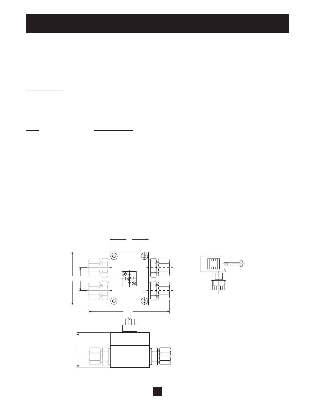
Appendix A (continued)
Differential Pressure Transducer
The sensors of this differential pressure transducer are two piezoresistive silicon pressure sensors,
mounted on a tape (TAP) freely floating in an oil chamber. The pressure is transferred to the sensor by a
separate steel diaphragm in the oil chamber.
Specifications
Range (FS): 4 bar (differential)
Over-pressure-Pmax: 16 bar (single-sided)
Class of protection: IP 65
Type Sealed gauge:
Signal Output: 0,5 - 4,5 V DC (ratiometric)
Supply: 5 VDC +/- 10%
Load Resistance: ≥ 5 kΩ
Linearity: ± 0.20 % FS; max. ± 0.5% FS
Stability: ± 0.1 % FS; max. ± 0.2% FS
Operating Temperature: -10 - +80°C
Storage Temperature: -40 - +100°C
Material: Body and diaphragm: 1.4435 Stainless Steel
Screw Joint and Cover:
44
60 26
INCL. 2m CABLE
Out (white)
≈ 95
+ Vcc (brown)
GND (green)
Screen
PLUG: mPm 193
40
40
Page 46

Appendix B
AQUA V AR Model 56 Controller Drive Head Technical Data
AQUAVAR Model 56
Controller Protection
Type Rated output Voltage
AV 1.1 1 HP 1 x 230 V / 40-60 Hz 3 x 230 V 4,8 A 10 Ampere
AV 1.15 2 HP 1 x 230 V / 40-60 Hz 3 x 230 V 7,0 A 10 Ampere
AV 1.2 3 HP 1 x 230 V / 40-60 Hz 3 x 230 V 10,0 A 16 Ampere
Input V oltage: 1 x 230 VAC ± 10% (An input line reactor is highly recommended
for areas which experience voltage fluctuation.)
Output V oltage: 3 x 230 V olt AC
Max. Frequency: 40 – 60 Hz – selectable
Min. Frequency: 0 - f-max
Electrical Efficiency: > 95%
Protection against: Short circuit, under-voltage, overheating of the electronics (overload) and
additional protective functions via external switch (motor temperature,
low water).
A power supply filter is included to ensure interference immunity.
The AV Series frequency converter complies with the general EMV provisions and has been tested according
to the following standards:
• Radio Interference Suppression EN 50081 P art 2 and EN 50082 Part 2
Supply Motor
Voltage
• High Frequency Field Interference ENV 50140 and ENV 50141
• Static Electricity Discharge EN 61000-4
• Disturbance V oltage EN55011
Ambient Temperature: 5° C – 40° C
Storage Temperature: -25° C – +55° C
(+70° C during max. 24 hours)
Humidity: rH max. 50% at 40° C, unlimited
RH max. 90% at 20° C, max. 30 days per year
Condensation not permitted!
Air Pollution: The air may contain dry dust as found in workshops where there is no
excessive quantity of dust due to machines. Excessive amounts of dust,
acids, corrosive gases, salts, etc. are not permitted.
Class of Protection: UL, CUL, NEMA 4, IP 55
Altitude: Maximum 3000 feet above sea level. Consult factory for higher altitudes.
41
Page 47

Appendix B (continued)
Drive Head Technical Data (continued)
X2 1 - Ground Connection
2 - Actual value input 0.5 - 4.5 VDC, 50 ohm load resistance
3 - Power source for external control, 5 VDC
4 - Ground connection for external on/off
5 - External on/off connection, 10K ohm, 5 VDC gold plated contact.
If no external control is used, a jumper wire is installed on contacts 4 and 5.
6 - Ground connection for low water switch
7 - Low water switch connection. If no switch is used a jumper wire is installed
on contacts 6 and 7.
8 - Connection for thermistor
9 - Connection for thermistor
10 - Normally closed contact for slave pump
11 - Common contact for slave pump
12 - Normally open contact for slave pump
X3 1 - RS 485 connection. S10 - (low) for connection of AQUA V AR Model 56 Controller to other
AQUA V AR Model 56 Controller units in a set.
2 - RS485 interface connection. S10 + (high) for connection of the AQUAVAR Model 56
Controllers to other AQUA V AR Model 56 Controller units.
3 - RS485 interface connection. Common ground.
4 - RS485 interface connection. +SVDC output signal. Maximum 20m Amp output.
NOTE: When connecting the variable speed pumps (max. 4 pumps) via the interface RS485, the
terminals X3 #1, X3 #2, X3 #3 are to be connected in parallel by means of a shielded cable
to every AQUAVAR Model 56 Controller drive head.
42
Page 48

This warranty applies to all water systems pumps manufactured by Goulds Pumps.
Any part or parts found to be defective within the warranty period shall be replaced at no charge to the dealer during the warranty period. The warranty period shall
exist for a period of twelve (12) months from date of installation or eighteen (18) months from date of manufacture, whichever period is shorter.
A dealer who believes that a warranty claim exists must contact the authorized Goulds Pumps distributor from whom the pump was purchased and furnish complete
details regarding the claim. The distributor is authorized to adjust any warranty claims utilizing the Goulds Pumps Customer Service Department.
The warranty excludes:
(a) Labor, transportation and related costs incurred by the dealer;
(b) Reinstallation costs of repaired equipment;
(c) Reinstallation costs of replacement equipment;
(d) Consequential damages of any kind; and,
(e) Reimbursement for loss caused by interruption of service.
For purposes of this warranty, the following terms have these definitions:
(1) “Distributor” means any individual, partnership, corporation, association, or other legal relationship that stands between Goulds Pumps and the dealer in
purchases, consignments or contracts for sale of the subject pumps.
(2) “Dealer” means any individual, partnership, corporation, association, or other legal relationship which engages in the business of selling or leasing pumps
to customers.
(3) “Customer” means any entity who buys or leases the subject pumps from a dealer. The “customer” may mean an individual, partnership, corporation, limited
liability company, association or other legal entity which may engage in any type of business.
THIS WARRANTY EXTENDS TO THE DEALER ONLY.
Goulds Pumps and the ITT Engineered Blocks Symbol are
registered trademarks and tradenames of ITT Industries.
GOULDS PUMPS LIMITED WARRANTY
© 2002 Goulds Pumps
Printed in USA
www.goulds.com
 Loading...