


Model
H-5223
Owner’s Manual


Model
H-5223
Data Collection Platform
Owner’s Manual
Rev: 1.00
NOTICE
This product embodies technology that is confidential and proprietary technology of DESIGN
ANALYSIS ASSOCIATES, INC., and which is protected by United States copyright laws and
international copyright treaty provisions, and/or by contract and applicable laws of trade secrecy.
These include all Software, Printed Circuit Board Artwork, Schematic Diagrams, and
Technologies applied therein. The enclosure encasing the electronics of this instrument may not
be opened without written consent of DESIGN ANALYSIS ASSOCIATES, INC., and any
attempt to do so without such written authorization constitutes a breach of contract and will also
void any applicable warranty for the product.
Design Analysis Associates, Inc.
75 West 100 South
Logan, UT 84321 USA
Phone: (435) 753-2212
Fax: (435) 753-7669
Internet: www.waterlog.com
E-mail: sales@waterlog.com


H-5223 Features
! Programming and data retrieval is through the serial port to a PC or a PDA using off the shelf
software. No special software required for normal operation.
! Same type of serial user interface as the XL series data logger allows current XL users a
quick learning curve.
! Compact menus built around PDA systems.
! Four general purpose analog input channels. Very high resolution with differential
measurements on channels 1 and 2.
! A precision 5.000 volt excitation that turns on automatically for each scan and a 12.0 volt
unregulated excitation programable to be turned on for each scan or left on all the time.
! Two digital I/O ports for general purpose I/O, pulsed or continuous outputs, counter inputs,
or a single quadrature input.
! Complete serial interface provides both a command mode for automated use and a menu
mode for human interaction. Both modes provide complete system programming and data
retrieval.
! Built-in data logging functions which store the data in non-volatile internal memory.
! Built in GOES radio supports 100, 300, and 1200 Baud GOES transmissions.
! Built in GPS time keeping for the GOES radio.
! Easily upgrades as the GOES radio in an XL series data logger system.
! Designed to be compatible with all SDI-12 sensors.
DOES NOT HAVE
! No frequency input options
! No 4 -20 mA output options
! No spare serial ports for applications requiring other serial devices.
! No built in functions or BASIC programming ability.
! No sensor mode for multiplexer operation.
! No built in display or key pad.
! Simplified data file system allows only 4 files all built in.
! Only a 5.0 volt input on the analog inputs.


User Agreement/
W
ATER
1. NATURE OF THE PRODUCT
This agreement accompanies a pressure measuring system comprising firmware, circuitry and other
electronic equipment in an enclosed housing, and packaged together with written instructional materials.
The packaged electronic circuitry and instructional materials herein are collectively referred to as the
“PRODUCT.” The PRODUCT is made available from DESIGN ANALYSIS ASSOCIATES, INC., of
75 West 100 South, Logan, Utah 84321 (hereinafter referred to as “DESIGN ANALYSIS”), and contains
information and embodies technology that is confidential and proprietary to DESIGN ANALYSIS, and
the availability and use of the PRODUCT is extended to you, the USER, solely on the basis of the terms
of agreement which follow.
2. ACKNOWLEDGMENTS BY USER
Opening the package which encloses the accompanying PRODUCT indicates your acceptance of the
terms and conditions of this agreement and constitutes an acknowledgment by you of the confidential and
proprietary nature of the rights of DESIGN ANALYSIS in the PRODUCT.
3. DUTIES OF YOU, THE USER
In consideration for the access to and use of the PRODUCT extended to you by DESIGN ANALYSIS
and to protect the confidential and proprietary information of DESIGN ANALYSIS, USER agrees as
follows:
LOG® Warranty
(a) USER agrees that they will not remove from the exterior of the housing of the
PRODUCT any safety warnings or notices of proprietary interest placed thereon by
DESIGN ANALYSIS.
(b) USER agrees that they shall not disassemble or otherwise reverse engineer the
PRODUCT.
(c) USER agrees to treat the PRODUCT with the same degree of care as USER exercises in
relation to their own confidential and proprietary information.
4. TERM
USER may enjoy these rights only as long as their possession of the PRODUCT shall continue to be
rightful. These rights will cease if the PRODUCT is returned to DESIGN ANALYSIS under the terms of
any redemption offer, warranty, or money-back guarantee, or if USER transfers the PRODUCT to
another party on terms inconsistent with this agreement.
5. LIMITED WARRANTY
(a) What is Covered
DESIGN ANALYSIS warrants that for a period of twelve months from the time of delivery the
functions to be performed by the PRODUCT will be substantially in compliance with USER
documentation. DESIGN ANALYSIS also warrants that the PRODUCT will be free from
defects in materials and workmanship for a period of ONE YEAR from the date of delivery.
(b) What USER Must Do
H-5223
User Agreement/W
ATER
LOG® Warranty W-1

If the product fails to satisfy the above warranty, USER must notify DESIGN ANALYSIS in
writing within the applicable period specified above and reasonably cooperate with the directions
they received from DESIGN ANALYSIS.
(c) What DESIGN ANALYSIS Will Do
DESIGN ANALYSIS will repair the PRODUCT or will endeavor to provide a replacement of
same within a reasonable period of time. In the event that DESIGN ANALYSIS is unable to
make the necessary repairs or replacement within a reasonable period of time, the original
purchase price will be refunded upon the return of the PRODUCT to DESIGN ANALYSIS.
(d) Limitations
(i) THE ENTIRE REMEDY FOR BREACH OF THIS LIMITED WARRANTY
SHALL BE LIMITED TO REPLACEMENT OF THE DEFECTIVE PRODUCT
OR REFUNDING OF THE PURCHASE PRICE, AS SET FORTH ABOVE.
IN NO EVENT WILL THE LIABILITY OF DESIGN ANALYSIS TO USER
OR TO ANY OTHER PARTY EXCEED THE ORIGINAL PURCHASE PRICE
OF THE PRODUCT, REGARDLESS OF THE FORM OF THE CLAIM.
(ii) EXCEPT FOR THE EXPRESS WARRANTIES ABOVE, DESIGN ANALYSIS
SPECIFICALLY DISCLAIMS ALL OTHER WARRANTIES, INCLUDING,
WITHOUT LIMITATION, ALL IMPLIED WARRANTIES OF
MERCHANTABILITY AND FITNESS FOR A PARTICULAR PURPOSE.
(iii) UNDER NO CIRCUMSTANCES WILL DESIGN ANALYSIS BE LIABLE
FOR SPECIAL, INCIDENTAL, CONSEQUENTIAL, INDIRECT, OR ANY
OTHER DAMAGES OR CLAIMS ARISING FROM THE USE OF THIS
PRODUCT, THIS INCLUDES LOSS OF PROFITS OR ANY OTHER
COMMERCIAL DAMAGES, EVEN IF ADVISED OF THE POSSIBILITY OF
SUCH DAMAGES. IN NO EVENT WILL DESIGN ANALYSIS BE LIABLE
FOR ANY CLAIMS, LIABILITY, OR DAMAGES ARISING FROM
MODIFICATION MADE THEREIN, OTHER THAN BY DESIGN
ANALYSIS.
(iv) THIS LIMITED WARRANTY GIVES USER SPECIFIC LEGAL RIGHTS.
USER MAY ALSO HAVE OTHER RIGHTS WHICH VARY FROM STATE
TO STATE. SOME STATES DO NOT ALLOW LIMITATIONS ON HOW
LONG AN IMPLIED WARRANTY LASTS OR THE EXCLUSION OF
INCIDENTAL OR CONSEQUENTIAL DAMAGES, SO THOSE
LIMITATIONS OR EXCLUSIONS MAY NOT APPLY.
6. GOVERNING LAW
This Agreement and its validity and interpretation shall be governed by the laws of the State of Utah,
notwithstanding any choice of law rules of Utah or any other state or jurisdiction.
W-2 User Agreement/W
ATER
LOG® Warranty
H-5223


Table of Contents
User Agreement/W
Chapter 1 Introduction
1.1 Introduction to the H-5223 . . . . . . . . . . . . . . . . . . . . . . . . . . . . . . . . . . . . . . . . . . . . . . . . . 1-1
1.2 Unpacking the H-5223 . . . . . . . . . . . . . . . . . . . . . . . . . . . . . . . . . . . . . . . . . . . . . . . . . . . . 1-1
1.3 About the Manual . . . . . . . . . . . . . . . . . . . . . . . . . . . . . . . . . . . . . . . . . . . . . . . . . . . . . . . . 1-2
1.4 Manual Updates . . . . . . . . . . . . . . . . . . . . . . . . . . . . . . . . . . . . . . . . . . . . . . . . . . . . . . . . . 1-2
1.5 Web Page Support . . . . . . . . . . . . . . . . . . . . . . . . . . . . . . . . . . . . . . . . . . . . . . . . . . . . . . . . 1-2
Chapter 2 Hardware Options and Installation
2.1 Hardware Overview . . . . . . . . . . . . . . . . . . . . . . . . . . . . . . . . . . . . . . . . . . . . . . . . . . . . . . . 2-1
2.2 Front Panel Connections . . . . . . . . . . . . . . . . . . . . . . . . . . . . . . . . . . . . . . . . . . . . . . . . . . . 2-1
2.2.1 Earth Ground Lug . . . . . . . . . . . . . . . . . . . . . . . . . . . . . . . . . . . . . . . . . . . . . . . . . 2-1
2.2.2 Com Port RS-232 . . . . . . . . . . . . . . . . . . . . . . . . . . . . . . . . . . . . . . . . . . . . . . . . . 2-2
2.2.3 Analog Input Section . . . . . . . . . . . . . . . . . . . . . . . . . . . . . . . . . . . . . . . . . . . . . . 2-2
2.2.3.1 Analog Input Channels . . . . . . . . . . . . . . . . . . . . . . . . . . . . . . . . . . . . . . . . 2-3
2.2.3.1.1 Differential input Option . . . . . . . . . . . . . . . . . . . . . . . . . . . . . . . . . . . . . . 2-3
2.2.3.2 Analog Grounds . . . . . . . . . . . . . . . . . . . . . . . . . . . . . . . . . . . . . . . . . . . . . 2-3
2.2.3.3 Switched +5.00 Volt Reference Excitation . . . . . . . . . . . . . . . . . . . . . . . . . 2-4
2.2.4 Digital I 01 and 2 . . . . . . . . . . . . . . . . . . . . . . . . . . . . . . . . . . . . . . . . . . . . . . . . . 2-5
2.2.5 SDI 12 Section . . . . . . . . . . . . . . . . . . . . . . . . . . . . . . . . . . . . . . . . . . . . . . . . . . . 2-6
2.2.6 Power Connections . . . . . . . . . . . . . . . . . . . . . . . . . . . . . . . . . . . . . . . . . . . . . . . . 2-6
2.3 Top Panel Description . . . . . . . . . . . . . . . . . . . . . . . . . . . . . . . . . . . . . . . . . . . . . . . 2-7
2.3.1 GOES Antenna . . . . . . . . . . . . . . . . . . . . . . . . . . . . . . . . . . . . . . . . . . . . . . . . . . . 2-7
2.3.2 Aux +12VDC / Ground . . . . . . . . . . . . . . . . . . . . . . . . . . . . . . . . . . . . . . . . . . . . . 2-7
2.3.3 Fail Safe Button. . . . . . . . . . . . . . . . . . . . . . . . . . . . . . . . . . . . . . . . . . . . . . . . . . . .2-7
2.3.4 LED Indicators . . . . . . . . . . . . . . . . . . . . . . . . . . . . . . . . . . . . . . . . . . . . . . . . . . . . 2-7
2.3.5 GPS Antenna . . . . . . . . . . . . . . . . . . . . . . . . . . . . . . . . . . . . . . . . . . . . . . . . . . . . . 2-8
2.3.6. Host and Aux Port (RS-232) . . . . . . . . . . . . . . . . . . . . . . . . . . . . . . . . . . . . . . . . 2-8
2.4 Testing the Installation . . . . . . . . . . . . . . . . . . . . . . . . . . . . . . . . . . . . . . . . . . . . . . . 2-8
ATER
LOG® Warranty . . . . . . . . . . . . . . . . . . . . . . . . . . . . . . . . . . . . . . . . W-1
Chapter 3 Menu Mode Operation
3.1 Menu Mode Interface . . . . . . . . . . . . . . . . . . . . . . . . . . . . . . . . . . . . . . . . . . . . . . . . . . . . . . 3-1
3.2 General Operations . . . . . . . . . . . . . . . . . . . . . . . . . . . . . . . . . . . . . . . . . . . . . . . . . . . . . . . 3-1
3.2.1 PDA Operations . . . . . . . . . . . . . . . . . . . . . . . . . . . . . . . . . . . . . . . . . . . . . . . . . . 3-2
3.3 Main Menu Screen . . . . . . . . . . . . . . . . . . . . . . . . . . . . . . . . . . . . . . . . . . . . . . . . . . . . . . . . 3-2
3.4 V- View Status . . . . . . . . . . . . . . . . . . . . . . . . . . . . . . . . . . . . . . . . . . . . . . . . . . . . . . . . . . . 3-3
3.5 I - Sensor Input Options . . . . . . . . . . . . . . . . . . . . . . . . . . . . . . . . . . . . . . . . . . . . . . . . . . . . 3-5
3.5.1 Digital I/O Setup (Encoder Setup) . . . . . . . . . . . . . . . . . . . . . . . . . . . . . . . . . . . . 3-5
3.5.2 Analog Setup . . . . . . . . . . . . . . . . . . . . . . . . . . . . . . . . . . . . . . . . . . . . . . . . . . . 3-10

3.5.3 Generic SDI-12 Options . . . . . . . . . . . . . . . . . . . . . . . . . . . . . . . . . . . . . . . . . . . 3-12
3.6 Data Options . . . . . . . . . . . . . . . . . . . . . . . . . . . . . . . . . . . . . . . . . . . . . . . . . . . . . . . . . . . 3-14
3.7 Output Options . . . . . . . . . . . . . . . . . . . . . . . . . . . . . . . . . . . . . . . . . . . . . . . . . . . . . . . . . 3-16
3.7.1 L - Logging Options . . . . . . . . . . . . . . . . . . . . . . . . . . . . . . . . . . . . . . . . . . . . . . 3-16
3.7.2 G - GOES Radio Options . . . . . . . . . . . . . . . . . . . . . . . . . . . . . . . . . . . . . . . . . . 3-17
3.7.2.1. Self Timed Options . . . . . . . . . . . . . . . . . . . . . . . . . . . . . . . . . . . . . . 3-18
3.7.2.1.1 Random Options . . . . . . . . . . . . . . . . . . . . . . . . . . . . . . . . . 3-21
3.8 Scan Options . . . . . . . . . . . . . . . . . . . . . . . . . . . . . . . . . . . . . . . . . . . . . . . . . . . . . . . . . . . 3-24
3.9 Configure System . . . . . . . . . . . . . . . . . . . . . . . . . . . . . . . . . . . . . . . . . . . . . . . . . . . . . . . 3-25
3.9.1 Port Setup . . . . . . . . . . . . . . . . . . . . . . . . . . . . . . . . . . . . . . . . . . . . . . . . . . . . . . 3-25
3.9.2. Configuration Files . . . . . . . . . . . . . . . . . . . . . . . . . . . . . . . . . . . . . . . . . . . . . . 3-27
Chapter 4 Maintenance
4.1 Maintenance . . . . . . . . . . . . . . . . . . . . . . . . . . . . . . . . . . . . . . . . . . . . . . . . . . . . . . . . . . . . . 4-1
4.2 Trouble Shooting . . . . . . . . . . . . . . . . . . . . . . . . . . . . . . . . . . . . . . . . . . . . . . . . . . . . . . . . . 4-1
Appendix A Specifications . . . . . . . . . . . . . . . . . . . . . . . . . . . . . . . . . . . . . . . . . . . . . . . . . . A-1
Appendix B SDI-12 Command and Response Protocol
B.1 SDI-12 Command and Response Protocol . . . . . . . . . . . . . . . . . . . . . . . . . . . . . . . . . . . . . B-1
B.2 Standard SDI-12 Command Set . . . . . . . . . . . . . . . . . . . . . . . . . . . . . . . . . . . . . . . . . . . . . B-2
B.2.1 Measure Command . . . . . . . . . . . . . . . . . . . . . . . . . . . . . . . . . . . . . . . . . . . . . . . B-2
B.2.2 Initiate Verify Command . . . . . . . . . . . . . . . . . . . . . . . . . . . . . . . . . . . . . . . . . . . B-3
B.2.3 Send Data Command . . . . . . . . . . . . . . . . . . . . . . . . . . . . . . . . . . . . . . . . . . . . . . B-4
B.2.4 Send Acknowledge Command . . . . . . . . . . . . . . . . . . . . . . . . . . . . . . . . . . . . . . . B-4
B.2.5 Send Identification Command . . . . . . . . . . . . . . . . . . . . . . . . . . . . . . . . . . . . . . . B-5
B.2.6 Change Sensor Address . . . . . . . . . . . . . . . . . . . . . . . . . . . . . . . . . . . . . . . . . . . . B-6
H-5223 PC Menu Tree

Chapter 1
Introduction
1.1 Introduction to the H-5223
The H-5223 is an entry level Data Collection Platform (DCP) system for applications requiring
low cost and with limited parameters to be measured. The H-5223 DCP incorporates a high data
rate GOES transmitter with built in GPS, the most common sensor input options, and a basic data
logger. The ease of use and similarities to the XL Series DCP’s and data loggers make the H5223 very attractive to current and future XL users.
Uses, Functions, Features, and Attributes of the H-5223:
! Operates over a wide temperature range: - 40EF to +140EF (- 40EC to +60EC).
! Setup and data retrieval is through the serial port to a PC or a PDA using off the shelf
software.
! Automatic power shut-off after 5 minutes.
! Four general purpose analog input channels.
! Two digital I/O ports for general purpose I/O, counter inputs, or a single quadrature input.
! Complete serial interface provides both a command mode for automated use and a menu
mode for human interaction. Both modes provide complete system programming and data
retrieval.
! Built-in data logging stores the data in non-volatile internal memory.
! Built in GOES radio supports 100, 300, and 1200 Baud GOES transmissions.
! Designed to be compatible with all SDI-12 sensors.
1.2 Unpacking the H-5223
You should have received the following items:
! The H-5223 instrument.
! 2-position power terminal block.
! 13-position sensor I/O terminal block.
! GPS antenna with main cable and adaptor cable.
! GOES RF output adaptor cable to type N connector.
! The H-5223 Owner's Manual. (One per order).
! PC communication cable. (One per order).
Optional Items
! GOES antenna, cable, lightening protection (at an additional charge).
! Null Modem Adaptor and gender changer for use with PDA’s (available upon request)
H-5223 Introduction 1-1

1.3 About the Manual
This manual will show you how to properly install and operate your H-5223. The installation
procedures and operational functions are very simple and easy to use. Please take time to read
through the manual, it will help answer most questions you have concerning the H-5223 and it’s
capabilities. The web page at http://www.waterlog.com will have manual updates and advanced
sections of the manual in PDF format, allowing customers to print extra copies or newer versions
of the manual.
1.4 Manual Updates
As new versions of software are released, manual updates will also be provided. This section of
the manual will include the main changes from one version of firmware to the next.
Version 1.00 Initial Release
Version 1.01 Along with hardware change, fixed the reverse power protection.
1.5 Web Page Support
The web page at http://www.waterlog.com will provide ongoing support for the H-5223. This
includes advanced sections of the manual, new versions of the main manual, new firmware
updates, brochures, technical notes, PC support software, etc.
1-2 Introduction H-5223


Chapter 2
Hardware Options and Installation
2.1 Hardware Overview
This chapter describes the basic procedure for installing the H-5223 including wiring for power,
sensors and communications. For proper installation you will need:
! The H-5223 mounting hardware
! Small flat blade screw driver
! Power and communication cables
! Sensors as needed.
! The H-5223 owner’s manual
! Sensor owners manuals.
2.2 Front Panel Connections
Figure 2-1 illustrates the physical location for the I/O of the H-5223. This diagram will help
show
where to connect the different sensors to the H-5223.
Figure 2-1 H-5223 Main I/O Panel
2.2.1 Earth Ground Lug
On the left side of the H-5223 is an earth ground lug. This provides a connection point for
grounding the unit to earth ground. If there is no earth ground at the site, one should be installed.
H-5223 Hardware Options and Installation 2-1

2.2.2 Com Port RS-232
This is the main RS-232 port for communicating to the H-5223. The RS-232 port is used to
connect to a PC, PDA, modem, or other type of serial equipment for standard serial
communications. This port is configured as a DCE type of device. This means it will plug
directly into a PC (a DTE type device), but will require a NULL modem adaptor for connecting
to most PDA’s or a modem (a DCE type device). The NULL modem cable crosses the
communication lines allowing two similar devices to communicate. Figure 2-2 shows the pin
assignments for this port.
SERIAL PORT PIN-OUT
PIN DIRECTION NAME (DCE)
1 No Connect Data Carrier Detect
(DCD)
2 Output Receive Data (RD)
3 Input Transmit Data (TXD)
4 Input Data Terminal Ready (DTR)
5 Ground (GND)
6 Output Data Set Ready (DSR)
7 Input Request To Send (RTS)
8 Output Clear To Send (CTS)
9 No Connect Ring Indicator (RI)
Figure 2-2 Serial Port Pin Assignments
2.2.3 Analog Input Section
The first seven connections on the terminal block are used for analog input functions. This
includes four analog inputs, two analog grounds and one +5.00 volt excitation connection.
2-2 Hardware Options and Installation H-5223

2.2.3.1 Analog Input Channels
There are four analog input channels labeled Vin1 to Vin4. The input range is 0 to 5 volts DC
and the maximum input should not exceed 5.0 volts. Each input can be programmed with a slope
and an offset allowing the final value recorded for the input to be scaled to some units of measure
like temperature or wind direction. Programming the slope and offset will be discussed in detail
in chapter 3.
2.2.3.1.1 Differential Input Option
Channels 1 and 2 can be used together to form a single differential input channel. This option is
intended for bridge type of sensors like a strain gage. This type of sensor has two output signals
that are referenced to each other, not directly to ground. See figure 2.3.
Figure 2.3 Bridge Sensor
2.2.3.2 Analog Grounds
There are two analog ground connection points. In order to preserve signal integrity, it is
important to use the analog grounds only for sensors connected to the analog section of the
H-5223. The current flowing through an analog sensor is relatively small and normally very
stable. This provides stable voltages produced by these sensors. If a digital sensor has its ground
connection tied into the analog ground, the currents from the digital sensor will flow through the
analog circuitry causing voltage level shifts and noise based on digital switching. There should
be sufficient digital ground connection points for the digital sensors.
H-5223 Hardware Options and Installation 2-3

2.2.3.3 Switched +5.00 Volt Reference Excitation
The +5 Volt reference output is used for analog sensors requiring a precision reference voltage.
The output current source maximum level is 10 milliamps. Exceeding this limit will cause the
excitation to possibly sag, and result in possible data errors. The Analog to Digital converter uses
this excitation for its reference to provide a ratio-metric relationship for sensors using the
excitation. What this means is that if a sensor causes loading to the excitation and drags it down
to 4.75 volts for example, then the A/D converter will use the 4.75 volts as its reference, and
maintain a full scale input equal to the reduced excitation. To a point this will reduce errors in
data when the excitation is used. If the excitation is being loaded down and some analog input
channels are not using the excitation, but produce a voltage output on there own, then these
inputs will have a much greater error.
Figure 2-4 shows a simple resistive type of sensor that would be typical of a wind direction type
of sensor. On a wind direction sensor a change in direction caused a variable resistor to move
causing a change in output voltage that is proportional to the direction. In this example the +5Vx
is used to power the sensor.
Figure 2-4 Simple Resistive Sensor
2-4 Hardware Options and Installation H-5223

2.2.4 Digital I/O 1 and 2
Pins 9 and 10 of the terminal block provide connection points for the two digital I/O signals.
Notice pin 8 is a digital ground and is grouped with these two pins. When using the digital I/O’s
this ground pin should be used as the reference point. Do not use the analog grounds.
The two digital I/O signals can be configured independently as inputs or as outputs. In the input
mode, the signal has an internal pull up resistor of 51K Ohms. This allows a switch closure to
ground to activate the input. It can also be driven using 5.0 volt logic levels. As an output, the
drive capability is limited by a 100 Ohm protection resistor. The output will still be about 4.0
volts or higher with a 10.0 mA or less load. Transient protection is provided for this input to
prevent damage from static discharge or over voltage conditions. When both pins are configured
as inputs, they may be used as a quadrature shaft encoder input. Typical applications for these
digital I/O pins include tipping bucket counter inputs, on / off status inputs, output alarming,
triggering samplers, etc. Figure 2-3 shows a simplified schematic of how these pins are
configured.
Figure 2-5 Digital I/O Counter Input
H-5223 Hardware Options and Installation 2-5
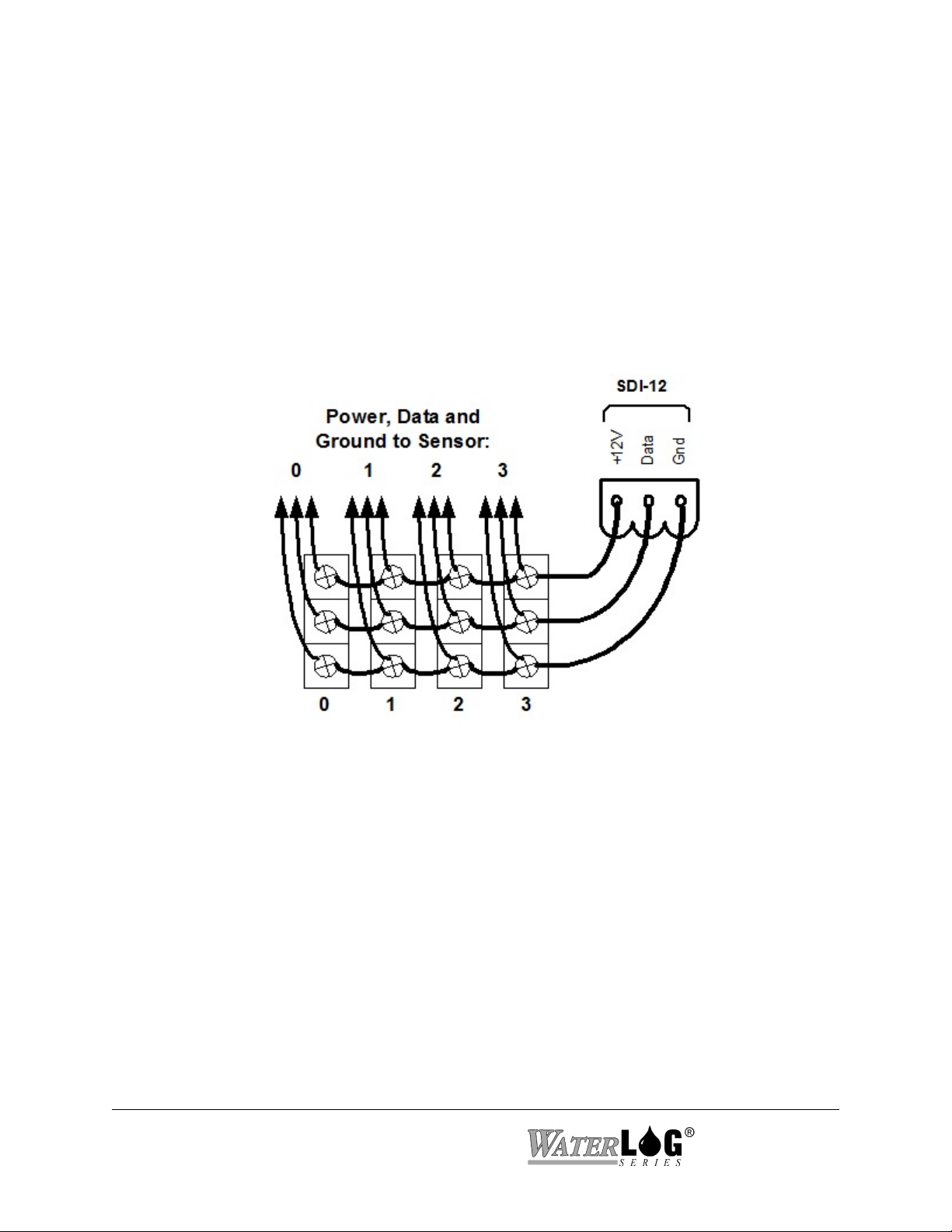
2.2.5 SDI-12 Section
Pins 11, 12, and 13 of the terminal block provide connection points for SDI-12 senors. The
+12Vsw power connection under the SDI-12 section is limited to about one amp so it may be
necessary to connect the SDI-12 sensor power line directly to the battery or to main power. This
excitation can be set to stay on continuously or to be switched on only at scan time.
If this excitation is to be turned on and off at scan time, then it may be necessary to have a warm
up delay after the excitation has turned on before starting to take measurements. The warmup
delay can be in the range of 0 to 9999 milliseconds.
If several SDI-12 sensors are to be connected to the H-5223, it may be necessary to use external
terminal strips to provide enough connection points.
Figure 2-6 SDI-12 Expanded Connector System
2.2.6 Power Connections
The last two pins at the far right of the terminal block provide the main connection points for
system power and ground.
NOTE: If the battery voltage is below 11.0 volts the GOES transmissions will stop. If the
battery voltage is below 9.5 volts, data logging will stop.
NOTE: When connecting to or removing the wires from these connection points, it is important
to remove the terminal block from the H-5223 first, or to have the other end of the
wires disconnected from the battery.
NOTE: Make sure scanning is turned off on units not being used to help preserve backup
battery life.
2-6 Hardware Options and Installation H-5223

2.3 Top Panel Description
On the top of the H-5223 are antenna connectors, power connectors, host and auxiliary
connectors, GOES fail safe button, and LED indicators
2.3.1 GOES Antenna
This is the GOES RF antenna connector and is a male SMA type of connector. Most GOES RF
antenna cables have an N type of connector so an adaptor will be needed to go from the one
connector type to the other.
2.3.2 +12VDC / Ground
This is the primary power connection to supply power to the transmitter.
2.3.3 Fail Safe Button
This button is used to manually reset the failsafe when it is tripped. The button needs to be
pressed and held in for 3 seconds to reset the failsafe.
2.3.4 LED indicators
Failsafe: Blinks to indicate that the failsafe has been tripped.
RF On (Solid): When LED is continuously on this indicates that a transmission is in
progress.
RF On (Blinking): When LED is blinking this indicates the transmitter failsafe timer is
running.
GPS On (Solid): When this LED is continuously on this indicates that the GPS receiver is
fixed onto 3 or more satellites.
GPS On (Blinking): When LED is blinking this indicates that the GPS is trying to acquire a
GPS fix.
2.3.5 GPS Antenna
This is the GPS antenna connector. The GPS antenna should be mounted in clear view of the
sky.
H-5223 Hardware Options and Installation 2-7

NOTE: When power is first applied to the unit it will try to sync the GOES time clock causing
the current draw to be around 35 mA. Once the time sync is complete the current will
return to the normal low power state. If the antenna is not installed the system may
continually draw higher current.
2.3.5 Host and Aux Port (RS-232)
The host port is used to connect the transmitter to an external data logger. The Aux port is used
to debug and monitor the status of the transmitter.
2.4 Testing the Installation
With a PC connected to the system and running a terminal emulation program like Pro Comm or
Hyper term, then when hooking up the battery a power up message is displayed on the PC screen.
This indicates that the battery is providing the proper power to the H-5223, and that system
variables have been initialized.
You will find detailed user setup information and menu options that will allow complete test and
verification of all sensor connections and operation in the next two chapters.
2-8 Hardware Options and Installation H-5223

Chapter 3
Menu Mode Operation
3.1 Menu Mode Interface
All communications with the H-5223 are through a command interface or menu interface using
the main RS-232 Serial Port. The menu interface is the default mode of operation. If in the
command interface, entering the command “MENU” will cause the system to enter the menu
mode. The menu mode is used to display a menu on the screen allowing simple human access to
the system options. To access either the menu or the command interface, the H-5223 must be
connected to a computer that is running some type of terminal program. The terminal program
must use the same communication settings as used by the H-5223. The default communication
values of the H-5223 are shown below along with other related options.
COMMUNICATION
SETTING
BAUD RATE:
DATA BITS:
STOP BITS:
PARITY:
DUPLEX:
TERMINAL EMULATION:
FLOW CONTROL:
All options available through the menu interface are also available using the command interface.
This chapter focuses on the menu interface only. When a computer is connected (direct
connection or modem connection), pressing the ENTER key will cause the main menu to be
displayed. It may take a second or two for the H-5223 to wake up and display the menu. If the
H-5223 seems slow pressing the ENTER key a few extra time will cause no problems. Once the
menu is displayed, the H-5223 is ready for interrogation. If no commands are received in a five
minute time period, the H-5223 will turn off automatically and return to a low power mode.
3.2 General Operations
DEFAULT H-5223
SETTING
9600
8
1
None
Full
VT-100
Software (Xon / Xoff)
OTHER H-5223
OPTIONS
(300 to 115K)
VT-52
None or Hardware
Each menu option is preceded with a letter or number that when pressed will activate the
indicated option. The ENTER key does not have to be pressed after an option key is pressed.
Some options will open a sub menu and others will allow the user to set or change a system
parameter. When in a sub menu, pressing the ESC key or the ‘B’ key will back up one menu. At
the main menu these keys will have no effect. Pressing the ENTER key or SPACE bar at any
time will refresh the current screen.
At the bottom of each menu screen is an “Ente r Opt i on > ” prompt. When an option key is
H-5223 Remote Operation (Menu Mode) 3-1

pressed that allows a system parameter to be changed, any additional information for that option
will be displayed after the prompt. There are two types of system parameter change options, first
is an option that requires direct keyboard input like a ‘Site Id’ or a column header label. The
second is an option that has a pick list of valid options such as an input source option. This type
of option allows the user to scroll through the valid options using UP and DOWN arrow keys.
Pressing the ENTER key will accept the displayed option. Pressing the ESC key will abort any
changes and restore the original selection.
3.2.1 PDA Operations
Knowing that PDA’s are often used in place of the PC, the menus have actually been designed to
be small so a PDA may be used easily with the system. In some cases the amount of information
in a single menu may be broken up into smaller segments to allow a proper fit on the PDA
screen. When M - More or N - Next is displayed this indicates there are more options that are
not displayed for that menu and pressing the ‘M’ or ‘N’ key will display the remaining part of the
menu. Also some PDA’s may use a hidden key approach for the ESC key so the ‘B’ key will
work like an ESC key when backing out of a menu. The ‘B’ key cannot be used to escape or
back out of an editing option as it may be valid for input. The ESC key still must be used to
escape out of an editing option.
PC’s still may be used with the H-5223 using a standard terminal emulation program. In this
case only a portion of the screen will be used.
3.3 Main Menu Screen
The following shows what the “Main Menu” screen looks like.
--- H-5223 Main Menu ---
V - View Status
I - Sensor Input Options
D - Data Options
O - Output Options
S - Scan Options
C - Configure System
X - Exit
Enter Option >
Each option in the main menu is a link to a submenu.
3-2 Remote Operation (Menu Mode) H-5223

V - View status: Displays system status information.
I - Sensor Input Setup: Used to configure the sensor input parameters.
D - Data Options: Allows the user to retrieve data from the unit, and check other data
file statistics.
O - Output Options: Defines how the data is stored, transmitted or displayed.
S - Scan Setup: Defines when and how often the unit scans the sensors.
C - Configure System: Sets basic system options such as time and date.
X - Exit: Exits the H-5223 Menu mode, and returns to low power mode.
3.4 V - View Status
The following shows what the “View Status Submenu” screen looks like. This screen allows the
user to view the current status of basic setup options and measurements. Options cannot be
changed in this menu.
--- View Status ---
Site ID: Site_ID
Time: HH:MM:SS
Date: MM/DD/YY
Scanning: Off
Next Scan: HH:MM:SS
GOES Mode: Off
M - More
Enter Option >
--- View Status --Battery: 12.8
Batt Max: 13.5
Batt Min: 12.6
System Resets: 001
Version: 1.00
R - Reset Batt & Resets
Enter Option >
Site ID:
This displays the system Site ID. The site ID is also the name used for the data files.
Time:
This is a status screen that shows the current time. There is no option here to change the
time. To change the time use the ‘Configure System’ menu.
H-5223 Remote Operation (Menu Mode) 3-3

Date:
This is a status screen that shows the current date. There is no option here to change the
date. To change the date use the ‘Configure System’ menu.
Scanning:
This is a status screen that shows if scanning is on or off. To turn scanning on or off use
the ‘Scan Setup’ menu.
Next Scan:
This is a count down timer until the next scan.
GOES Mode:
This identifies the current GOES Mode of operation. If the GOES radio is not
functioning a N/A will be displayed. Normally the N/A would only be displayed if the
system is or was operating on a low battery. Remove power for a few seconds and then
reconnect it. Make sure the battery is charged properly.
Battery:
There are three battery voltages listed: current voltage, maximum voltage measured, and
minimum voltage measured. The minimum and maximum values are mainly listed for
diagnostic reasons. If the minimum voltage is too low it may indicate that the battery is
being undercharged. If the maximum battery reading is too high it may indicate a faulty
regulator. The system will work properly between 11.5 and 15 volts. If the battery drops
below 11.5 then the radio will stop transmitting, but logging will continue. If the battery
voltage drops below 10.0 volts then the system stops logging and enters a low power
mode waiting for the power to be restored. Once the battery voltage raises to a normal
level the system will start logging and transmitting again.
System Resets:
This value shows how many times the system has been reset. A system reset can be
caused by several conditions; a loss of power, a power glitch or surge, a watchdog timer
resetting the system are a few. Normally a user will make sure this value is reset to ‘0'
before leaving the site on a site visit, then on the next visit checking this value to see if
any resets have occurred between the last visit an the current visit.
Version:
This is the current firmware version used by the system. New firmware versions may be
downloaded from the manufactures web page and loaded into the system by the user.
After a new version is loaded it is best to see that the checksum test still passes.
R - Reset Batt & Resets:
This option resets the Max and Min Battery voltage values to the current battery voltage
and resets the number of system resets to zero. When servicing a gauge site, use this
option to reset the battery values to the current battery value and to reset the number of
3-4 Remote Operation (Menu Mode) H-5223

system resets to zero. On the next visit to the site, review the condition of the battery
since the last visit by looking at the max and min values and the number of system resets.
Ideally, the number of resets would still be zero and the max and min battery values
would be within a normal operating range. A low minimum battery voltage could indicate
a weak charging system, a battery that is too small for the site, or bad wiring, etc. A low
battery could also cause the system to reset. System resets normally indicate a problem
with the battery voltage being too low, bad wiring, or poor power connections. Lightening
and other external factors may also cause the system to reset. A high maximum battery
voltage could indicate that the regulator is bad and that it is passing all of the energy from
the solar panel to the system.
3.5 I - Sensor Input Options
The “Sensor Input Options” menu shows the current values of all the sensor inputs. Also submenus are available for changing the setup parameters of each input. The following table shows
what the “Sensor Input Options” screen looks like.
--- Sensor Input Options ---
Dig I/O #1: 0.03 (CNTR)
Dig I/O #2: 1 (DIG IN)
Ana1: 0.903 Ana3: 1.232
Ana2: 1.343 Ana4: 57.344
D - Digital I/O Setup
A - Analog Input Setup
G - Generic SDI-12 Options
Enter Option >
3.5.1 D - Digital I/O Setup (Encoder Setup)
This sub menu will allow the user to configure the digital I/O section of the H-5223. This
includes defining the pin as an input or an output, and how it will be controlled. Below is the
menu for configuring the first Digital I/O. Digital I/O 2 will look the same as digital I/O 1.
--- Digital I/O 1 Setup ---
V - Dig I/O 1 Value: 1.0
M - I/O Mode: DIG IN
D - Pulse/Delay: 1000 ms
C - Cnt/Encdr Inc: 0.01
S - Trigger Source: Ana1
T - Trigger Type: > Set Pt
P - Trigger Set Pnt: 2.50
1 - Test Output
N - Next
Enter Option >
V - Digital I/O #1 = 1
This option displays the current value for the selected digital I/O. This option will act
differently based on the selected mode of operation for the I/O. Also in some modes (counter
H-5223 Remote Operation (Menu Mode) 3-5

input and encoder input) the value can be set to an initial starting point. Below is an
explanation of how this option works for each possible mode for the I/O pins.
Digital Input: This option is used as a status indicator showing the current state of the
digital I/O 1 pin. The value will always be a 1 or a 0. A 1 indicates the pin
is high or at approximately 5 volts, and a 0 indicates that it is low or at
approximately 0 volts. Trying to change the value while in this mode
using the ‘V’ option will have no affect. This pin is internally tied high so
with nothing connected it will show up as a 1.
Counter Input: This option is used to view the current counter value. The value may be
changed as needed by the user to set an initial offset using the ‘V’
command. This value is reset to 0.00 at power up.
Encoder Input: This option is used to view the current encoder value. The value may be
changed as needed by the user using the ‘V’ option.. This value is reset to
0.00 at power up.
On At Scan: This option will normally always indicate a 0, but the pin will be set high
or to 5 volts during the scan. At the end of the scan the pin will be set low
again or to 0.0 volts. During the scanning process the screen is not
updated so this will indicate 0 even during the scan when in actuality the
pin is at a high level. Trying to change the value for this mode will have
no affect.
Output Pulse: This option will normally always display a 0 as the screen is not updated
during the scan or when the output is tested, but the pin will be set high or
to 5.0 volts during the scan if the trigger condition is true. The pin will go
low again after the pulse / delay time has elapsed.
Output Cont.: This option will reflect the state the pin should be. For example if the pin
is to be driven high then the indicator will be a 1. If the output is to be
driven low then the indicator will be 0. There may be cases where the
output is loaded to a point it cannot go high or low. In this case the
indicator will show what the pin should be, but if the pin is measured with
a volt meter it may be at some other level.
A - I/O 1 Mode
This option is used to define if the digital I/O pin should be an input or an output. If the pin
is to be used as an input it may be used as a general purpose input, as a counter input, or as a
quadrature shaft encoder input in association with the other digital I/O pin. If the pin is to be
used as an output, the user may define it as a pulsed output, a continuous output, or turn on
automatically at the beginning of each scan. The different modes of operation for the digital
I/O’s are described below.
3-6 Remote Operation (Menu Mode) H-5223

Digital Input: General purpose input returns a 1 or a 0. Typical application is a gate
position, open or closed. This is the default mode.
Counter Input: The pin is used as a counter input. A falling edge (5 volts to 0 volts)
causes a counter to increment by the count / encoder inc value. Typical
application is a tipping bucket rain gauge.
Encoder Input: If both inputs are set to this mode then a standard quadrature shaft encoder
may be used for stage readings. Normally Phase A of the encoder would
be connected to digital I/O 1 and Phase B would be connected to digital
I/O 2. A ground wire is also connected between the encoder and the H-
5223. Each change of state of the encoder will cause the encoder value to
increment or decrement at a rate set by the count / encoder inc setting.
On At Scan: This is an output mode that will cause the pin to automatically turn on
(driven high) before each scan and turn off at the end of the scan. At the
beginning of the scan when this pin is driven high, the scanning process
will be delayed for a time period set by the ‘Pulse /Delay’ option. A
typical application is to turn on a pump during each scan.
Output Pulse: This output option is used to pulse or turn on the output for a duration set
by the ‘Pulse / Delay’ option if a user defined condition exists. This
output will be pulsed sometime during the scan process. The condition is
defined by using the ‘Trigger Source” option, the “Trigger Mode’ option
and the “Trigger Set Point” option as defined below. A typical application
is to trigger an automatic water sampler that requires a 1 second pulse to
start its process.
Output Cont. This output option is used to turn on the output continuously when a user
defined condition occurs and to stay on until the condition goes away. The
condition is defined by using the ‘Trigger Source” option, the “Trigger
Mode’ option and the “Trigger Set Point” option as defined below. A
typical application is to turn on a warning light when a water level is too
high. The condition will be evaluated on each scan.
NOTE: On output modes; the H-5223 checks to see if the digital output mode is set for
“Output Pulse” or “Output Cont.” automatically at the end of each scan if it is not
set as source for logging or for GOES. At this time the output is activated if
needed. If it is set as a source for logging or GOES then the user defined
condition is check at that point and the output set or cleared at that point in time,
not at the end of the scan.
D - Pulse Length / Warm Up Delay
This option is used to define a pulse length when the digital I/O is set for pulsed output mode
and is used to define a warm up delay when the digital I/O is set for “On At Scan” output
mode.
Pulsed Output Mode: As defined, the system checks the mode of the digital I/O and if it
H-5223 Remote Operation (Menu Mode) 3-7

is set for pulsed output mode and the trigger condition is true, then the output will be set
high for a duration based on this option. The range is from 1 to 9999 milliseconds.
On At Scan: At the beginning of each scan the system checks the mode of the digital
I/O and if it is set for ‘On At Scan’ then the digital I/O is set high and the system delays
before processing the scan for a duration based on this option. After the scan process is
complete the digital I/O will be turned off. An example application where this option
could used is for a motor that needs to be turned on at the beginning of each scan but
requires a delay of 2 seconds before the sensors are scanned. In this case, the warm up
delay would be set to 2000.
C - Count / Encoder Inc Value
When in Counter Mode, this is the value that will be added to the counter for each high to
low transition of the input. Also when in Encoder Input Mode, this is the value used for
counting up and down based on a change of the encoder.
S - Trigger Source
This option is used to select a data source to use to compare with the ‘Set Point’ to see if the
digital output should be set or not. For example, to set the output high if the battery voltage
is below 11.0 volts, the battery must be selected as the source, and the set point option set to
11.0 and the trigger mode set to ‘< Set Pt’. This reads as; “if the battery is less than 11.0
volts then set the output high, else set the output low”. The trigger source could be any of the
normal inputs such as analog inputs, a counter input, SDI-12, etc.
T - Trigger Mode
This option is used to select the type of condition to use to compare the trigger source and the
set point. The following show the valid options:
> Set Pt: Greater than set point. Set the output high if the source is greater than the
set point.
< Set Pt: Less than set point. Set the output high if the source is less than the set
point.
Always: Always set the output high regardless of the set point or source.
P - Trig Set Pt
This option is used to set the value the data source will be compared with to see if the digital
output should be set high or not.
1 - Test Dig 1 Output
When the digital I/O 1 pin is configured as an output, pressing the 1 key will activate the pin
for testing purposes. If the pin is configured for pulsed output, the output will turn on for the
defined pulse length and then turn off again. If the pin is configured for continuous operation,
3-8 Remote Operation (Menu Mode) H-5223

or for on at scan, pressing the 1 key will cause the output to toggle between high and low. If
the pin is configured as an input of any type the message ‘NA’ will be displayed.
N - Next
This option is used to move to digital I/O number 2.
NOTE: Digital I/O 2 is configured the same as digital I/O 1 so no further discussion is
given for the second digital I/O pin.
H-5223 Remote Operation (Menu Mode) 3-9

3.5.2 A - Analog Setup
These sub menus allow the user to configure an analog input channel with a slope and an offset,
and to view the current voltage applied to the input. Each analog input can be configured
independently. The screens below show the current state of the analog inputs and the default
slopes and offsets.
--- Analog Input Setup ---
Analog 1: 0.191
S - Slope: 1.000
O - Offset: 0.000
D - Differential Mode = Off
N - Next Input
Enter Option >
--- Analog Input Setup --—
Analog n: 2.462
S - Slope: 1.000
O - Offset: 0.000
N - Next Input
Enter Option >
S - Slope
There is a slope and offset coefficient for each analog input channel. The H-5223 uses the
slope and offset to calculate a converted value based on what the user has entered in for the
slope and offset. The equation used to calculate the converted value is as follows:
CONVERTED VALUE = RAW VOLTS * SLOPE + OFFSET
The slope and offset can be any valid real number. An example of using the slope would be
for a wind direction sensor that uses a potentiometer excited by the 5.000 volt excitation.
The raw voltage from the sensor would be in the range of 0 to 5 volts representing a direction
of 0 to 360 degrees. In this case a slope 72 .0 (which is [360 - 0 degrees] / [5 - 0 volts])
could be entered into the H-5223 and then the calculated value for the analog channel would
be in degrees for wind direction.
O - Offset
This is the offset coefficient for the analog input channel. Pressing the ‘O’ key allows this
3-10 Remote Operation (Menu Mode) H-5223

offset to be edited. An example of using the offset could be for a temperature sensor that has
a 0 to 5 volt output that represents a -40 to +60 degree C range respectfully. First calculate a
slope as follows:
Slope = (Max Degrees - Min Degrees) / (Max Volts - Min Volts)
Slope = (60 - (-40)) / (5 - 0) = 100 / 5 = 20
Now look at the basic equation and fill it in with known data. The slope is now known, and
we know that at 0 volts the temperature is -40 degrees.
Temperature = slope * volts + offset (Basic equation)
-40 = 20 * 0 + offset (Basic equation with known values added)
Notice that 20 * 0 is zero so that part of the equation is dropped, and the offset is left.
-40 = offset
This is the value that would be entered into the system for this type of sensor.
D - Differential Mode
Channels 1 and 2 can be configured as a differential input. When the differential mode is
‘On’ the value reported for channel 1 will be the difference between channel 1 and 2.
Channel 1 is the positive input of the differential pair. Channel 2 should not be used as a data
source for logging or for GOES but if it is used it will return the same value as channel 1.
3.5.3 G - Generic SDI-12 Options
The following shows what the “SDI-12 Options” screen looks like and is used to test SDI-12
sensors. SDI-12 sensors have a set of standard commands. This menu allows for the standard
commands to be sent by simply pressing a single key. Sensors may also have an extended
command set for specific options related to that sensor. There is also an option to edit an
extended command and send it to the addressed sensor.
--- SDI-12 Command Mode --T - Test Address: 0
A - Acknowledge
I - Identify
V - Verify
M - Measure
D - Data Retrieval
S - Send Extended
E - Edit Extended: XRS
P - +12Vx Mode: Always On
Enter Option >
H-5223 Remote Operation (Menu Mode) 3-11

T - Test Address
This is the SDI-12 address that will be used when any of the commands are sent to connected
sensors. This allows a single key press to send any of the standard SDI-12 commands. If “0”
was used as the Test Address, all SDI-12 commands would be directed to the sensor with
address “0.”
A - Acknowledge
This command sends the address followed by the “!” terminator. The normal response is the
sensor address followed by a Carriage Return and Line Feed. If the sensor is not connected or
does not respond, the H-5223 will respond with, “Communication Timed Out”.
I - Identify
This command sends the address followed by “I!” which is the standard SDI-12 identify
command. The normal response is the sensor address followed by general information about
the sensor such as version number, manufacture, etc. The command is terminated with a
Carriage Return and Line Feed. If an error occurs, the H-5223 will respond with
“Communication Timed Out.” Refer to the sensor manufacturer for proper response to the
Identify Command.
V - Verify
This command sends the address followed by “V!” which is the standard SDI-12 verify
command. The normal response is sensor specific information such as a memory test result. If
an error occurs, the H-5223 will respond with “Communication Timed Out.” Refer to the
sensor manufacturer for proper response to the Verify Command.
M - Measure
This command sends the address followed by “M!” which is the standard SDI-12 measure
command. If an error occurs, the H-5223 will respond with “Communication Timed Out”.
The normal response to this command is the address followed by 4 numbers. The first three
numbers is the amount of time required for the sensor to make the measurement and store the
data in a buffer making it ready for retrieval. The last number is the number of values that
will be returned when using the ‘D’ commands. Refer to the sensor manufacturer for a
detailed description of the response to the Measure Command.
D - Data Retrieval
This command sends the address followed by “D0!” which is the standard SDI-12 data
retrieval command. Executing this command prior to a completed sensor measurement will
abort the measurement and cause just the sensor address to be sent back. If an error occurs,
the H-5223 will respond with “Communication Timed Out.” Refer to the sensor
manufacturer for proper response to the Data 0 Command. There are cases where the data
retrieval command cannot retrieve all the data available. In this case a D1, D2 up to a D8
command may need to be sent to the sensor to retrieve all the data available.
3-12 Remote Operation (Menu Mode) H-5223

S - Send Extended
This command sends the test address followed by the user entered text in the “Edit Extended
Cmd” command option followed by “!”. If an error occurs, the H-5223 responds with
“Communication Timed Out.” Refer to the sensor manufacturer for proper response to the
corresponding Extended Command.
E - Edit Extended
This options is used to enter a non standard SDI-12 extended command to be sent to the
sensor. The address MUST NOT be included in this text and the command terminator “!” is
optional as both are added automatically when the extended command is sent.
P - +12Vx Mode
The +12 volt excitation can be set to be on at all times or only on for the scan. The default is
on at all times.
3.6 D - Data Options
The options under this menu allow the user to see the status of the data memory including how
full is the data memory and free bytes. Also the options to transmit and erase data. The
following shows what the “Data Options” screen looks like:
--- Data Options --Data Status: OK
Bytes Free: 2159520 (0.0% Full)
File Count: 0 of 8
T - Transmit Data
N - Transmit New Data
R - Reset New Data Pointer
F - Erase Last File
E - Erase All Data
Enter Option >
Data Status: This is a status indication regarding health of the data memory. Messages
may include ‘Erase Error’ ‘Write Error’, and ‘Warning over 50% full’, indicating it may be
good to save and then erase some data. If the system has filled the memory and it has started
to wrap around, the message “OK (Wrapped)” will be displayed.
Bytes Free: This is a status indication of how full the data memory is at the present time.
Data is stored in a compressed mode so each data value only takes 4 bytes.
There are 2159520 actual bytes available for data storage and each data value takes 4 bytes.
Therefore, the total number of data values able to be stored is 2159520 / 4 = 539880.
To calculate how long it will take to fill the data memory use the following equation.
(Bytes Free * Scan Rate in minutes) / (5760 * log columns defined) = days left to fill
memory.
H-5223 Remote Operation (Menu Mode) 3-13

For example, if there are 574000 bytes free, and the unit is set to log Date, Time, Ana1,
Ana2, and Battery every 15 minutes, that would be 5 columns defined, or 5 data values per
scan.
(574000 * 15) / (5760 * 5) = 298.95 days.
If all memory was available:
(2159520 * 15) / (5760 * 5) = 1124 days or just over 3 years.
The value 5760 comes from 4 bytes per data value multiplied by 1440 minutes in a day.
File Count: There can be up to 8 files of data stored on H-5223. Each time scanning is
turned on it will open a new file. If there are already 8 files the user will be prompted to
erase a file or all the data. If power is lost and then restored, this will not start a new file but
continues to log data to the last file.
NOTE: Once the data memory is full the system will ‘wrap’ in the existing file only. If
only one file exists then the system will be able to use all the memory for
wrapping. If the system already has one or more files that take up 80% of the data
memory when scanning is turned on, then the new file will only have 20% of
memory available for the ‘wrap’ function. For this reason it is best to save and
then erase data on a regular basis.
T - Transmit Data
This option allows the user to select a file to transmit over the RS-232 port. After selecting
this option, a list of files will be displayed. Use the Up and Down Arrow keys to select the
file to transfer. Once the file is selected, the user must select if the file will be transferred
using a straight ASCII file dump or using the XMODEM file transfer protocol. The
XMODEM protocol reduces transfer errors, and should always be used at the higher baud
rates.
N - Transmit New Data
This option is used to transmit only the newest data starting at a point in time based on the
‘New Data Pointer’. The ‘New Data Pointer’ is normally pointing at the end of the last data
transfer of new data. The normal process is to use this command to transmit the new data,
then use the next command, ‘Reset New Data Pointer’ to position the pointer at the end of the
data just transferred so the next time data is sent it will be a continuation of data starting
where this transfer ended.
3-14 Remote Operation (Menu Mode) H-5223

R - Reset New Data Pointer
This option resets the new data pointer to the current file position. If the new data pointer is
reset to the current file position, then the next time the ‘Transmit New Data’ option is used
the data transfer will start at this point in time.
F - Erase Last File
This option is used to erase the last file only. This frees up room for the next file. When this
option is used the user will be prompted to confirm the erase operation.
E - Erase Data
This option allows the user to erase all of the data stored by the H-5223. This frees up all data
memory. When this option is selected the user will be asked if they want to proceed with the
erase operation. Pressing any key but the “Y” will abort the erase process.
3.7 O - Output Options
The following shows the “Output Options” screen. The options in this menu lead to sub- menus
used to setup logging and the GOES radio.
--- Output Options —--
L - Logging Options
G - GOES Radio Options
Enter Option >
L - Logging Options
The sub menus here allow easy setup of the data logging options.
G - GOES Radio Options
The sub menus here allow easy setup of the GOES radio options for both self timed and
random transmissions.
3.7.1 L - Logging Options
The logging options are used to determine if and how the data will be stored to the internal
memory of the H-5223. The following shows the “Logging Options” screen. Notice the brackets
around the 01 for the first column indicating any changes will apply to this column only. These
brackets may be moved to the desired column using the Right and Left Arrow keys. There will
be a total of 20 columns.
H-5223 Remote Operation (Menu Mode) 3-15

--- Logging Options ---
Column | [01]
---------------|---------S - Source: | Date
H - Header: | MM/DD/YY
D - Digits: | 2
-> Next
<- Previous
Enter Option >
S - Source
This selects what input will be used to provide data for the selected column. Options included
are Date, Time, Ana1 to Ana4, Dig1, Dig2, Batt, SDI-12 inputs, etc. If “None” is selected as
the source, the selected column and all subsequent columns will be disabled.
NOTE: If data is to be transmitted using the GOES radio the data also must be logged.
H - Header
This option allows the user to enter a label of choice for each column. The label will be used
to identify the data as it is displayed using other options. For example the label will be
printed at the top of the columns as the data is stored to the data card.
D - Digits
This sets the number of digits to the right of the decimal that will be logged with the data
value. This has no affect on the Date and Time sources.
-> Next
This moves the screen to the next column. This option has no effect on the last column.
<- Previous
This reverses the screen to the previous column. This option has no effect on the first column.
3.7.2 G - GOES Radio Options
This section explains the operation of the GOES radio system. The following shows the “GOES
Radio Option” screen. These options are used to set up both self timed and random
transmissions.
3-16 Remote Operation (Menu Mode) H-5223

--- GOES Main Menu —--
Time: HH:MM:SS
M - Mode: Off
A - Address: ABCD1234
S - Self Timed Options
R - Random Options
D - Diagnostics
Enter Option >
Time
This is the DCP time and is automatically set to international standard time by the GPS
system. The user cannot set or change the time manually. The data logger time clock is
separate from this time clock and is can be set to local time.
M - Mode
This allows the user to define the GOES Radio mode of operation. Options include Off, Self
Timed Transmissions Enabled, Random Transmissions Enabled, and both Self Timed and
Random transmissions enabled. This option should only be turned on after all other GOES
options are defined.
NOTE: The GOES mode cannot be turned on if the GOES clock has not been set by the
GPS system.
A - Address
This is the 8 character DCP ID assigned by NESDIS.
3.7.2.1. S - Self Timed Options
This screen shows the “Self Timed Transmissions” options:
--- Self Timed Options —--
C - Channel Number:
000
R - Transmit Rate:
HH:MM:SS
O - Tx Offset Time:
HH:MM:SS
W - Self Timed Window: 1
Min
S - Self Timed Baud Rate:
100
D - Data Format Options
T - Transmit Options
Enter Option >
H-5223 Remote Operation (Menu Mode) 3-17

C - Channel Number
This is the Self Timed channel number assigned by NESDIS. This may also be referred to as
the primary channel.
R - Transmit Rate
This is the transmit rate assigned by NESDIS.
O - Tx Offset Time
This is the transmission time relative to midnight. This is assigned by NESDIS. The offset
time must be less than the transmit rate value.
W - Self Timed Window
NESDIS will assign a window length indicating how much time is allowed to transmit data.
The default is a 15 second window. The options range from a 1 minute to a 5 second window.
B - Self Timed Baud Rate
This option is used to set the baud rate for the Self-Timed transmissions. This may be
different than the random transmission baud rate. This option is dependent on the radio type
and will be 100, 300 or 1200 baud. This will also be assigned by NESDIS.
D - Data Format Options
This opens a new menu dealing with options to define how the data will be formatted. Below
is the Data Format Menu.
--- ST Data Format —--
F - Data Format: SHEF
D - Data Order: SCAN
N - Data Sent First: Newest
H - Send SHEF Headers: No
A - Append 1 Battery Scan:
Yes
S - Scans / Transmission: 8
Enter Option >
F - Data Format
Self-Timed transmissions can be either a SHEF or a binary format. The SHEF format
uses plain ASCII text and is easily readable, but it takes longer to transmit the message.
On the other hand, binary data is transmitted quicker, but the message will need to be
decoded before it can be read. If more data is required, then a binary format may have to
be used. Refer to the GOES Data Format section for more details on the SHEF format
and the GOES binary format. This option cannot be edited while scanning and GOES are
enabled.
3-18 Remote Operation (Menu Mode) H-5223

D - Data Order
The options here are ‘Scan Order’ which is the default mode and ‘Channel Order’. In
‘Scan Order’, each line of data will contain one data value from each sensor all measured
at the same time. There will be one data value for each sensor set for transmission and
the number of lines is equal to the scans per transmission. In ‘Channel Order’, each line
of data will contain data values from a single input over a range of time. The number of
data values per line will be equal to the scans per transmission. The number of lines will
be equal to the number of sensors setup to be transmitted.
Scan Order: Each line of data represents one scan and one value from each data source.
HG TA VB
18.34 22.78 12.45
18.76 22.45 12.44
18.97 22.15 12.45
19.43 22.02 12.45
Channel Order: Each line represents all of the data from a single sensor.
HG 18.34 18.76 18.97 19.43
TA 22.78 22.45 22.15 22.02
VB 12.45 12.44 12.45 12.45
N - Data Sent First
This options selects between newest data being transferred first or oldest data being
transferred first, (ascending or descending data order). The default is newest data first.
H - Send SHEF Headers
The SHEF code for each data value may be defined by the user. This is normally a two
character entry that represents the data values. For example “HG” represents Height of
the Gauge, and “TA” represents Ambient Temperature.
SHEF headers are turned on, printed on top line
Stage, Temp, and Battery values in each line. Each
line represents a different scan at some defined time
interval.
Each line contains all of the scanned data from a
single sensor. Each data value is from a different time
based on scan rate.
A - Append 1 Battery Scan
This option, if set to “Yes,” will send one battery reading at the end of each transmission.
S - Scans / Transmission
This option indicates how much data should be sent in each transmission. The default is 8
scans per transmission. When using a 1 hour transmission rate and a scan rate of 15
minutes, the 8 scans will include the 4 most recent scans of new data plus 4 scans of
redundant data for a total of 2 hours of data.
H-5223 Remote Operation (Menu Mode) 3-19

T - Transmit Options
This screen shows the “Self Timed Transmit Options”. This is used to define the data to be
transmitted.
--- ST Transmit Options ---
Column | [01]
---------------|------------
S - Source: | None
C - SHEF Code: |
F - Format: | XX.XX
-> Next
<- Previous
Enter Option >
S - Source
This selects what input will be used to provide data for the selected column. Options
include Date, Time, Stage, Temp, Batt, AnaX, Counts, SDI-12 inputs, etc. If “None” is
selected, that column and all subsequent columns are disabled. Normally date and time
are not used for GOES data.
NOTE: If data is to be transmitted using the GOES radio the data also must be logged.
C - SHEF Code
This allows the user to enter a SHEF code for each column. For example “HG”for the
stage or “TA” for the temperature. The code will be used to identify the transmitted data.
F - Format
This options determines how many digits to display before and after the decimal point.
This is only valid when data is transmitted using the SHEF (ASCII) data format. For
negative numbers the polarity sign ‘-‘ will take up one character location. For example a
format of xx.xx will have a range of -9.99 to 99.99.
-> Next
This advances the screen to the next column. If on the last column then this option has no
effect.
<- Previous
This moves the screen to the previous column. This option has no effect if on the first
column.
3-20 Remote Operation (Menu Mode) H-5223

3.7.2.1.1 Random Options
This screen shows the “Random Transmissions” options:
--- Random Options —--
C - Channel Number: 000
R - Transmit Rate: 00:00:00
U - Random BaudRate: 100
A - Alarm Source: None
Y - Alarm Type: > Set Pt
P - Alarm Set Point: 1.00
T - Transmit Options
Enter Option >
C - Channel Number
This is the random channel number assigned by NESDIS. This may also be referred to as the
secondary channel.
R - Transmit Rate
This option defines the time interval in which the random transmissions will be sent. A
transmission will happen at random in this time period when the trigger condition is true. A
good rule of thumb is to keep this rate the same as the scan rate.
U - Random Baud Rate
This option is used to set the baud rate for the random transmissions. This may be different
than the Self-Timed transmission baud rate. This will be 100, 300 or 1200 baud. This will also
be assigned by NESDIS.
A - Alarm Source
This option is used to select a data source to use to compare with the ‘Set Point’ to see if a
random transmission should be sent or not. For example, to send a transmission if the battery
voltage is below 11.75 volts, the battery must be selected as the source, and the set point
option set to 11.75 and the alarm type set to ‘< Set Pt’. This reads as; “if the battery is less
than 11.75 volts then send a transmission, else do not transmit”. The alarm source could be
any of the normal inputs such as analog inputs, a digital input, SDI-12, etc.
Y - Alarm Type
This option is used to select the type of condition to use to compare the alarm source and the
set point. The following show the valid options:
> Set Pt: Greater than set point. Transmit if the source is greater than the set point.
< Set Pt: Less than set point. Transmit if the source is less than the set point.
Always: Always transmit regardless of the set point or source.
H-5223 Remote Operation (Menu Mode) 3-21

P - Alarm Set Point
This option is used to set the value the data source will be compared with to see if the unit
should transmit.
T - RR Transmit Options
This screen shows the “RR Transmit Options” screen. This screen is used to select the data
that will be transmitted during a random transmission. Pressing the S key allows the user to
select a valid data source from a list of valid options. Valid options are the same as those with
the ST Transmit Options such as AnaX, Dig1, or SDI01. The maximum number of data values
that can be transmitted during a random transmission is 5. Pressing the Right and Left Arrow
keys will allow the user to select any of the 5 available data columns. Random data will
always be sent using the GOES binary format.
--- RR Transmit Options —--
Column: | [01]
---------------|-----------
-S - Source: | None
-> Next
<- Previous
Enter Option >
D - Diagnostics
Options under this menu allow the user to see if the radio is setup properly and to look for
problems if they arise.
--- GOES Diagnostics —-Main ST Buffer Byte Count:
61
Radio ST Buffer Byte Count: 0
Bytes used: 61
Bytes Available: 550
Est. Tx Time: 6 seconds
V - View ST Buffer Data
R - View RR Buffer Data
F - Force RR Transmission
Enter Option >
Main ST Buffer Byte Count
There is a data buffer in the H-5223 that continuously holds the data that will be transmitted.
This section of the menu displays the number of bytes in the buffer. This buffer can be
viewed at any time to see the data that will be transmitted by the GOES radio. To view the
buffer press the ‘V’ key as shown on the menu. If the radio is not enabled, the viewed data
will be a series of slashes “/” or “@” characters representing the selected data format. When
the radio is turned on and scanning is started the slashes will be replaced with real data. This is
3-22 Remote Operation (Menu Mode) H-5223

an easy way to see if the data format and setup information is correct.
Radio ST Buffer Byte Count
The data in the main buffer will be transferred to the radio buffer at the end of the last scan
before the next scheduled transmission. This status screen normally shows a 0 byte count
except after the scan just before the transmission. One minute after the transmission is sent
this value will go back to 0 indicating the data has been sent.
Bytes Used and Bytes Available
This status screen indicates how many bytes are used and how many bytes are available for the
current settings. If too much data is defined to be transmitted then the byte count will be
greater than the bytes available. In this case the user will have to make choices on how to cut
back on the amount of data being transmitted.
Est. Tx Time
This is an estimated time needed for the transmission based on the current settings. Amount
of data to be sent, baud rate, headers turned on and off, etc all can affect the transmission time.
This time must be less than the defined transmit window size.
V - View ST Buffer
This option allows the user to view the main ST buffer at any time. See the section above
‘Main ST Buffer Byte Count’ for more details.
R - View RR Buffer
This option allows the user to view the random buffer at any time.
F - Force Random Tx
Pressing the F key will allow the user to test the random transmission setup by forcing a
random transmission. The data sent will be the data defined by the user under the random
transmission setup options.
3.8 S - Scan Options
The following shows the “Scan Options” screen. All functions of the H-5223 are based around the
scanning process.
--- Scan Options —--
Current Time: HH:MM:SS
Next Scan: HH:MM:SS
S - Scanning: Off
R - Scan Rate: HH:MM:SS
N - Next Scan At: HH:MM:SS
Enter Option >
H-5223 Remote Operation (Menu Mode) 3-23

Current Time
This shows the current data logger time. This is for reference only and can not be changed
here.
Next Scan
This shows the time remaining until the next scan occurs. Normally it will be less than the
scan rate.
S - Scanning
This option allows the user to enable or disable the scanning process.
NOTE: If scanning is off no data will be logged and no data will be transmitted.
R - Scan Rate
This option allows the user to define how often the H-5223 will scan the sensors.
N - Next Scan At
This shows the time when the next scan will occur. The user may also use this option to set
when the next scan should happen. This option is disabled when scanning is off and enabled
when scanning is on.
3.9 C - Configure System
--- Configure System —-T - Time: HH:MM:SS
D - Date: MM/DD/YY
S - Sync to GPS: ON
Z - UTC offset (min): 0
I - Site ID: Site_ID
P - Port Setup
C - Configuration Files
R - Reset Defaults
U - Update Firmware
Enter Option >
T - Time
This option is used to set the system time, normally set to local time or to international
standard time. The time format is HH:MM:SS.
D - Date
This option is used to set the system date. The default format is MM/DD/YY, but it may be
changed using the date format option.
S - Sync to GPS
This option instructs the H-5223 to automatically obtain it’s time from the GPS receiver
located in the transmitter.
3-24 Remote Operation (Menu Mode) H-5223

Z -UTC offset
This option allows the user to specify an +/- offset in minutes from the UTC time obtained
from the GPS receiver.
I - Site ID
This option allows the user to enter in an eight character label that defines the site. This will
also be used as the filename for the data file when scanning is turned on.
NOTE: Valid site ID names may include letters, numbers, or the underscore. Spaces and
the decimal point are not valid characters for the site ID and should be avoided.
3.9.1 P - Port Setup
The following options only apply to the main serial port. It may be configured to work with
several types of modems or other systems.
--- Serial Port Setup —--
R - Baud Rate: 9600
F - Flow Control: SW
E - Emulation: VT-100
S - Startup Mode: Menu
Enter Option >
R - Baud Rate
This option sets the baud rate for the serial port. The default is 9600 which will be used for
nearly all applications. Other valid baud rates range from 115200 down to 1200.
F - Flow Control
Flow control is used to pace the data through the serial port. It is important not to send data
faster than the receiving system can receive it. There are two types of flow control, software
and hardware flow control.
Software flow control (SW) is also referred to as XON / XOFF. When this is enabled the
receiving system will send a character (XOFF) to the H-5223 instructing it to stop sending
data until the receiving system can catch up. At the point the receiving system is ready it will
send an XON to the H-5223 indicating it is ready for more data. Software flow control is the
default selection.
NOTE: If using XMODEM protocol for data file transfers, software flow control should
not be used as a binary checksum value is calculated for each block of data and
transferred with the data block. If the binary checksum value is the same as an
XOFF command, then the system may stop the data transfer prematurely.
Hardware flow control uses two extra pins on the 9 pin connector. This is ‘Request to Send’
H-5223 Remote Operation (Menu Mode) 3-25

(RTS) and ‘Clear to Send’ (CTS). Normally a PC connected to the H-5223 will turn on the
CTS signal when it is ready to communicate and watches the RTS signal before it sends
anything to the H-5223. The same type of monitoring will be done by the H-5223, It will not
send anything to the PC if CTS is not on and will turn on RTS indicating to the PC it is ready.
NOTE: Hardware flow control should only be enabled on the PC when the H-5223 is
turned on. If hardware flow control is enabled on the PC and the H-5223 is off, the
PC will not be able to turn on the H-5223 because the PC will wait for the RTS
signal to go active before sending the wake up characters, and RTS will only go
active when the H-5223 is turned on over the serial port.
E - Emulation
Terminal emulation is used to control computer screen operations like clearing the screen or
moving the curser around to update different portions of the screen without having to redraw
the complete screen. If the information on the screen appears to be from the H-5223 but is
displayed in abnormal places or intermixed with abnormal characters, then emulation is the
most probable cause of the problem. The emulation modes supported are VT-52 and VT-100
with VT-100 as the default.
S - Startup Mode: Menu
The startup mode selection is ‘Menu’ mode or ‘Command’ mode. Menu mode is the default
and allows for simple human interaction to setup and retrieve data from the system. In
command mode the H-5223 is normally set up for automatic data collection from a host
computer, or a program on a host computer has been developed to provide a different user
interface.
3.9.2 C - Configuration Files
This option is selected by pressing ‘C’ and is for saving application specific configuration files on
a PC or to setup the H-5223 from a configuration file already on a PC. The screen is displayed
below.
--- Configuration Files —--
S - Send Setup Data
P - Setup From PC File
Enter Option >
S - Send Setup Data
This option is used to send the setup information to a PC. The PC will need to be configured
to capture the ASCII data. The setup information will be saved in a file named by the user and
is dependant on the PC terminal emulation program on how this is done.
3-26 Remote Operation (Menu Mode) H-5223

P - Setup from PC File
This option is used to setup the H-5223 from a file previously stored on the PC.
R - Reset Defaults
This option will reset all of the H-5223 user definable options back to the factory default values.
U - Update Firmware
This option is used when loading new firmware into the H-5223. When this option is used follow
the instructions on the screen and in any readme type of files provided with the new firmware.
New firmware will be available as needed from the web page, www.waterlog.com.
NOTE: Be sure to save your data and a configuration file before loading new firmware into
the unit. After the unit is updated with the new firmware it is best to reset all
options back to the factory defaults, then load back in the old configuration file.
The time and date will also need to be checked as they will normally be reset in
this process.
H-5223 Remote Operation (Menu Mode) 3-27

Chapter 4
Maintenance/Trouble Shooting
4.1 Maintenance
Sustained operation of the H-5223 is almost maintenance-free. There are no desiccant or
serviceable parts to maintain. As with any precision instrument, the calibration should be
checked or verified on a regular basis.
4.2 Trouble Shooting
It is unlikely that this manual will ever contain trouble shooting tips to cover every problem that
will be encountered. Feedback from customers is very valuable and greatly aids in the quest for
constant product enhancement. Please feel free to call the factory for technical assistance and
also with solutions you have found to past problems.
Our experience with DCP’s has taught us a lot about the problems associated with field installed
equipment. The following list of problems and possible solutions will undoubtedly grow with
subsequent revisions of this manual and may be helpful to you.
No SDI-12 Response From SDI-12 Sensor:
1 - Verify power to the sensor.
2 - Check all SDI-12 connections, power, data and ground.
3 - Check the pin out of your Sensor for correct wiring.
4 - Make sure all sensors have a unique address.
5 - Test the sensor with it being the only sensor connected to the data logger.
Intermittent Data:
1 - Check your power and ground connections. Moisture over time will oxidize and
corrode connectors and pins.
2 - Verify your power supply or battery voltage. As the power supply approaches the
lower threshold of the H-5223 supply range, it may begin to miss readings
intermittently.
3 - Read the status messages, Min, and Max values, and system resets of the H-5223 for
a possible malfunction or clue to the problem.
H-5223 Maintenance/Trouble Shooting 4-1

Artificially High or Low Data:
1 - Check the slope and offset for the channel reading high. If it is an SDI-12 sensor
make sure it is programmed correctly.
2 - Measure the +5.0 volt excitation to see if it is ok.
3 - Try using a warm up delay before taking measurements.
4 - Check battery voltage and all connections.
GOES not transmitting:
1 - Check power to the GOES radio, do so under a load.
2 - See if the GOES time is correct, if it is stopped, it indicates power to the radio was
lost, stopping the clock. The radio will not transmit if the GOES clock is not
running.
3 - Check all antenna wires.
4 - Check antenna alignment.
5 - Use a power meter to measure the power output of the radio, and the reflected power.
4-2 Maintenance/Trouble Shooting H-5223

Appendix A
Specifications
Performance
Gener al A n alog In put
Channels: 4 (Single Ended / Differential on 1 and 2)
Resolution: 20-Bit Resolution (1 Part in 1,048,576)
Accuracy: ± 0.075%
Input Range: 0 to 5 Volts (All Channels)
Excitation 5.000V Switched, with 10mA (max load)
± 3.5 mV Over Load and Temperature Range
12 V unregulated, switchable, 100 mA load.
Digita l I/O / Cou nte r In put
Channels: 2, Independently configured as digital input,
counter input or digital output.
Input Voltage: 0-5 Volt
High Level: 3.5 V (min)
Low Level: 0.8 V (max)
Output Voltage:
Low: 0.4 V (max)@ -5mA
High: 3.5 V (min)@+5mA
Data Stora ge
Type: Non-Volatile FLASH
Size: 2 Mega Byte (539880 data values)
Interf ace
SD I-1 2 SDI-12 Master Mode
Protocol: SDI-12, 7-bit even parity, 1 stop bit
Baud Rate: 1200
RS-23 2 RS-232 Communication Port (DCE)
Protocol: RS-232, 8-bit, no parity, 2 stop bits
Baud Rate: Programmable, 1200 to 115,200
Po w er
Input Voltage: 12.0 V nominal, 15 V absolute maximum
11.00 Volts or greater for GOES and logging
9.50 Volts or greater for logging only
Input Current: Sleep Mode: < 1 mA
Active: 30 mA maximum
Transmit < 2.75 A
Frequency Stability
Over Temperature: ± 0.4 PPM
Long Term: ± 1 PPM (including temperature)
Frequency Setting: To an accuracy of 1 Hz under
software control
Output Power
100 / 300: 7.1 Watts (nominal) Linear
1200: 11.2 Watts (nominal) Linear
Output Dependence: 50 Ohms, short and open circuit
protected
Time Keeping: < 0.5 seconds with GPS Receiver
Certification: NOAA/NESDIS certified for self-
timed and random transmissions
Environment
Humidity: 90% non-condensing
Temperature Range:
-Operating -40E to +50E C (-40E to +122E F)
-Storage -55E to +75E C (-67E to +167E F)
Mechanical Data
Enclosure: Non Sealed, corrosion resistant aluminum case
Accesso ries: - 9-pin D connector cable required for RS-232
communication (H-350-RSC, 1 per order)
- Sensor / Power Terminal Block
- GPS Antenna and cable
- RF cable / adaptor to type N connector
- Gender Changer and Null modem Adaptor
available upon request (for use with PDA’s)
Warranty
The WATERLOG H-5223 is warranted against defects in materials
and workmanship for one year from date of shipment.
NOTE: Specifications subject to change without prior notice due
®
to ongoing commitment to testing and product
enhancement.
GOES : H-2221 (100, 300, 1200 baud HDR
Radio with built-in GPS)
Frequency Coverage
100 and 300 BPS: Standard GOES Channels (1-266)
1200 BPS: HDR Domestic Channels (1-133)
H-5223 Appendix A Specifications A-1


Appendix B
SDI-12 Command and Response Protocol
B.1 SDI-12 Command and Response Protocol
This is a brief description of the Serial Digital Interface (SDI-12) Command and Response
protocol used by the WATERLOG Series Model H-5223. Refer to the document "A SERIAL
DIGITAL INTERFACE STANDARD FOR HYDROLOGIC AND ENVIRONMENTAL
SENSORS." Version 1.1 November, 1993 Coordinated by Campbell Scientific, Inc., Logan,
Utah.
During normal SDI-12 communications, a master device will communicate with one or more
slave devices. The master is a DCP or data logger and slave devices are sensors. The H-5223 is
a master device. The H-5223 (master) sends an address together with a command to an SDI-12
sensor as needed or requested. The sensor then replies with a "response" to the command. In the
following descriptions, SDI-12 commands and responses are enclosed in quotes. The SDI-12
address and the command/response block terminators are defined as follows:
"a" Is the sensor address. The following ASCII Characters are valid
addresses: "0" to "9", "A" to "Z", and "*". Sensors are normally initially
programmed at the factory with the address of "0" for use in single sensors
systems. Addresses "1" to "9" and "A" to "Z", can be used for additional
sensors connected to the same SDI-12 bus. The H-5223 can only work
with sensors at address 0 to 9.
®
"!" This is the command termination character and is the last character of a
command block from the master.
"<cr><lf>" Are carriage return (0D) hex and line feed (0A) hex characters. They are
the last two characters of a response block from a sensor.
Notes:
All commands/responds are upper-case printable ASCII characters.
Commands must be terminated with a "!" character.
Responses must be terminated with <cr><lf> characters.
The command string must be transmitted in a contiguous block with no gaps of more than
1.66 milliseconds between characters.
A break of at least 12 milliseconds is sent out before the first command. If the sensor does
not respond to this command, the master will send the command again for a total of three
tries. If this break and three command sequence does not have a valid response the break is
sent again and three more tries to send the command. This will happen for a total of three
breaks with three tries of sending the command for each break. If the sensor does not
respond to any of the commands then the master gives up on this sensor and moves on to the
next task.
H-5223 SDI-12 Command and Response Protocol B-1

All ASCII-Hex commands, arguments and data values are transmitted most significant digit
first.
B.2 Standard SDI-12 Command Set
All SDI-12 sensors should incorporate a set of standard commands. These commands are used
for making measurements, collecting data, identifying the sensor and verifying the sensor is
working properly. Since all sensors use the same basic commands it is easy to memorize and use
these commands on any sensor. The H-5223 has a built in menu that allows for a single key
press to activate the standard commands for testing purposes. There is also an option to edit and
send out non standard commands as each sensor could have a set of commands specific only to
its operation. When using the H-5223 with SDI-12 sensors it is important to have a manual
available for each sensor to see the exact response from the sensor for each command.
B.2.1 Measure Command
The Measure Command causes a measurement sequence to be performed. Data values generated
in response to this command are stored in the sensor's buffer for subsequent collection using "D"
commands. The data will be retained in the sensor until another "M" or "V" command is
executed.
Command Response Description
------------------ ---------------------- ------------------------------------
"aM!" "atttn<cr><lf>" Initiate measurement
Where:
a Is the sensor address ("0" to "9", "A" to "Z", or "*").
M Is the command indicator, M for Measure, and must be in upper case.
ttt Is a three digit integer (000-999) specifying the maximum time, in seconds, the
sensor will take to complete the command and have measurement data available
in its buffer.
n Is a single digit integer (0-9) specifying the number of values that will be placed in
the data buffer. If "n" is zero (0), no data will be available using subsequent "D"
commands.
Upon completion of the measurement, a service request "a<cr><lf>" is sent to the data recorder
indicating the sensor data is ready. The data recorder may wake the sensor with a break and
collect the data any time after the service request is received or the specified processing time has
elapsed.
B-2 SDI-12 Command and Response Protocol H-5223

B.2.2 Send Data Command
The Send Data command returns sensor data generated as the result of previous "aM!" or "aV!"
command. Values returned will be sent in 33 characters or less. The sensor's data buffer will not
be altered by this command.
Command Response
------------- --------------------------------------
"aD0!" through "aD9!" "apd.d ... pd.d<cr><lf>"
Where:
a Is the sensor address ("0" to "9", "A" to "Z", or "*").
D0..D9 Are upper-case ASCII characters.
p Is a polarity sign (+ or -).
d.d Represents numeric digits before and/or after the decimal. A decimal may
be used in any position in the value after the polarity sign. If a decimal is
not used, it will be assumed to be after the last digit.
For example: +3.29 +23.5 -25.45 +300
If the number of values returned by a "aD0!" command is less than the number specified by the
result of the previous "M" or "V" command, the rest of the data must be collected using "aD1,"
"aD2!" .... "aD9!" until all values specified have been collected.
If one or more values were specified and a "aD0!" returns no data (a<CR><LF> only), it means
that the measurement was aborted and a new "M" or “V” command must be sent.
H-5223 SDI-12 Command and Response Protocol B-3

B.2.3 Initiate Verify Command
The Verify Command may cause a verify of tests or procedures to be performed. The result of
this command is similar to the "aM!" command except that the values generated can be fixed test
data, test results, etc. The data generated in response to this command is placed in the sensor's
buffer for subsequent collection using "D" commands. The data will be retained in the sensor
until another command is executed.
Command Response Description
------------- ------------------------- ---------------------------
"aV!" "atttn<cr><lf>" Initiate verify sequence
Where:
a Is the sensor address ("0" to "9", "A" to "Z", or "*").
V Is an upper-case ASCII character.
ttt Is a three digit integer (000-999) specifying the maximum time, in seconds, the
sensor will take to complete the command and have data available in its buffer.
n Is a single digit integer (0-9) specifying the number of values that will be placed in
the data buffer. If "n" is zero (0), no data will be available using subsequent "D"
commands.
B.2.4 Send Acknowledge Command
The Send Acknowledge command returns a simple status response which includes the address of
the sensor. Any measurement data in the sensor's buffer is not disturbed.
Command Response
------------- -------------------------
"a!" "a<cr><lf>"
Where:
a Is the sensor address ("0" to "9", "A" to "Z", or "*").
B.2.5 Send Identification Command
B-4 SDI-12 Command and Response Protocol H-5223

The Send Identification command responds with sensor vendor, model, and version data. Any
measurement data in the sensor's buffer is not disturbed.
Command Response
------------- ------------------------------------------------------------
"aI!" "allccccccccmmmmmmvvvxx...xx<cr><lf>"
Where:
a Is the sensor address ("0" to "9", "A" to "Z", or "*").
I Is an upper-case ASCII character.
ll Is the SDI-12 version compatibility level, e.g. version 1.0 is represented as
"10".
cccccccc Is an 8 character vendor identification to be specified by the vendor and
usually in the form of a company name or its abbreviation.
mmmmmm Is a 6 character field specifying the sensor model number.
vvv Is a 3 character field specifying the sensor version number.
xx...xx Is an optional field of up to a maximum of 13 characters to be used for
serial number or other specific sensor information not relevant to operation
of the data recorder.
B.2.6 Change Sensor Address
The Change Sensor Address command allows the sensor address to be changed. The address is
H-5223 SDI-12 Command and Response Protocol B-5

stored in non-volatile EEPROM within the sensor. The H-5223 will not respond if the command
was invalid, the address was out of range, or the EEPROM programming operation failed.
Command Response Description
------------- ------------------------- ---------------------------
"aAn!" "n<cr><lf>" Change sensor address
Where:
a Is the current (old) sensor address ("0" to "9","A" to "Z", or "*"). An ASCII "*"
may be used as a "wild card" address if the current address is unknown and only
one sensor is connected to the bus.
A Upper-case ASCII character.
n Is the new sensor address to be programmed ("0" to "9", "A" to "Z", or "*").
NOTE: To verify the new address use the "Identify Command."
B-6 SDI-12 Command and Response Protocol H-5223

Appendix C
Remote Operation (Command Mode)
Rev 1.01
C.1 Command Interface
The H-5223 has a command interface mode for applications that require another computer
systme to communicate with the H-5223 through the RS-232 port. Commands are used to setup,
monitor and control the H-5223. To access the command interface, the H-5223 must have the
startup mode set to command mode. The connected computer must be running some terminal
emulation program or some custom software to control communications on the serial port. The
following list shows the default serial port settings of the H-5223.
BAUD RATE: 9600
DATA BITS: 8
STOP BITS: 1
PARITY: N
DUPLEX: FULL
TERMINAL EMULATION: VT52
When the computer is connected and ready to communicate, pressing the ENTER key will cause
the command interface prompt to be displayed. This prompt is an arrow “->” on the left side
of the screen. The first key press wakes up the H-5223 but it may take a second for the prompt to
be displayed. Once the prompt is displayed the H-5223 is ready to receive commands. If no
commands are received in a five minute time period the H-5223 will turn off automatically,
returning to a low power mode.
The command interface is best suited for communications with other computer equipment. The
command interface allows a user to easily develop their own custom interface, or for RS-232
devices to access the H-5223 inputs and outputs. For human interaction with the H-5223 the
menu interface is normally used as discussed in chapter 3. This chapter will give a detailed
description of the commands used by the command interface.
All commands must be terminated with a carriage return and a line feed character. The “5”
character in the examples is used to represent the ENTER key and signifies a carriage return and
a line feed being sent to the H-5223. Any parameters must follow the command as described
with the proper spacing between the command and the parameter. The command may be in
upper or lower case. When starting in command mode the characters typed on the host system
will be received by the H-5223 and echoed back to the host system. This allows the user to
verify that what was typed was also received by the H-5223. The BACKSPACE key may be
H-5223
Remote Operation (Command Mode) C-1

used to edit characters on the command line. Echoing the command may be turned off using the
‘ECHO=OFF’ command. The commands listed below are grouped into categories based on the
function of the command.
The H-5223 has three basic types of commands:
Read Commands: The command to read each value consists of the value name, followed by
“?”. For example, to read the time, the command is “TIME?”. The H-5223 response will be
similar to “TIME = 12:34:56".
Write commands: The command to write each value consists of the value name, followed by
“=”, and then the new value. For example, to set the date, the command is “DATE=05/05/99".
There is no response to a write command.
Action Commands: These simply consist of the command. For example,
“RESETSTATUSVALUES”, or “PURGENOW”.
Below is a table of commands. In the table, commands followed by “?” are values that can be
read, commands followed by “=” are values that can be written, and commands followed by
“?/=” are values that can be read and written. Action commands have no special character
following.
SYSTEM COMMANDS
COMMAND DESCRIPTION
TIME?/= Current time (normally set to local time)
DATE?/= Current date (normally set to local date)
SITEID?/= Site ID
BAUDRATE?/= Baud rate of the communications port
FLOWCONTROL?/= Hardware or software flow control (or none)
CHARACTERDELAY?/= Delay between characters out the comm port
LINEDELAY?/= Delay after line-feeds out the comm port
RESETDEFAULTS Reset settings to system defaults
C-2 Remote Operation (Command Mode)
H-5223

STATUS COMMANDS
FIRMWAREVERSION? XL™ firmware version
CHECKSUM? Diagnostic to verify firmware integrity
BATTERY? Current battery voltage
BATTMIN? Lowest measured battery voltage
BATTMAX? Highest measured battery voltage
SYSTEMRESETS? Number of system resets
RESETSTATUSVALUES Resets BattMin, BattMax, and SystemResets
DATA FILE COMMANDS
ERASEINTERNALDATA Erase data from internal memory
DIRINTERNALDATA Directory of internal data
DUMPINTERNALDATAFILE <name> Transmit the file out the serial port
INTERNALDATABYTESUSED? Number of bytes used in internal memory
INTERNALDATABYTESFREE? Number of bytes free in internal memory
ERASENEWDATA Erase data since last retrieval.
ERASEDATACARD These commands are valid only on the XL series
DIRDATACARD
DUMPDATACARDFILE <filename>
DATACARDBYTESUSED?
DATACARDBYTESFREE?
COPYDATATOCARD
data logger, but since software for a PDA has
already been developed using these commands we
may still need these commands to respond with
some message like “No Card Installed” I need to
see the response on the XL to know for sure.
H-5223
Remote Operation (Command Mode) C-3

SCANNING COMMANDS
SCANNING?/= Scanning on or off
SCANRATE?/= Amount of time between scans
NEXTSCAN? Amount of time until next scan
NEXTSCANAT?/= Time of next scan
SENSOR INPUT COMMANDS (Analog Inputs)
ANALOG1-4? Analog sensor value
ANALOG1-4SLOPE?/= Analog sensor slope
ANALOG1-4OFFSET?/= Analog sensor offset
DIGITAL I/O COMMANDS
DIGITAL1-2? Return the value of digital 1 or 2.
DIGITAL1-2= Set digital x to the indicated value (for counter
mode).
DIGITAL1-2MODE?/= Digital mode (input, pulse, continuous, counter ...)
DIGITAL1-2TRIGGERSOURCE?/= Source of value to evaluate for alarm conditions
DIGITAL1-2TRIGGERTYPE?/= Trigger type (always, > set point, ...)
DIGITAL1-2TRIGGERPOINT?/= Point with which the source value is compared
DIGITAL1-2PULSELENGTH?/= Length in ms of output pulse or warmup delay
COUNTERSLOPE?/= Counter slope
RESETCOUNTERS Reset all of the counters
C-4 Remote Operation (Command Mode)
H-5223

SDI-12 COMMANDS
SDITESTADDRESS?/= Address used when sending SDI-12 commands
SDIACKNOWLEDGE Send an acknowledge command
SDIIDENTIFY Send an identify command
SDIVERIFY Send a verify command
SDIMEASURE Send a measure command
SDIDATAn Send a collect data command
SDIEXTENDED=<command> Send a custom extended command
OUTPUT COMMANDS
AUTOPRINT?/= Data being logged also gets sent out serial port
LOGGING COMMANDS
LOGGING?/= Log data to internal memory
LOGCOLUMN1-25SOURCE?/= Source of flash card output column
LOGCOLUMN1-25HEADER?/= Column header for flash card output
LOGCOLUMN1-25SKIPRATE?/= Skip rate for flash output column
LOGCOLUMN1-25DIGITS?/= # of digits to print for flash column
H-5223
Remote Operation (Command Mode) C-5

GOES COMMANDS
GOESMODE?/= Off, Timed, Random, Both
GOESADDRESS?/= 8 character address, assigned by NESDIS
GOESTIME?/= International standard time
GOESSTCHANNEL?/= Self timed channel number
GOESSTRATE?/= Self Timed transmit rate
GOESSTOFFSET?/= Offset from midnight to first transmit
GOESSTFORMAT?/= Format of Self Timed data (SHEF, binary, etc.)
GOESSTORDER?/= Order of Self Timed data
GOESSTSENDSHEFCODES?/= Send SHEF codes with each transmit (yes, no)
GOESSTAPPENDBATTERY?/= Send 1 battery reading at end of transmission
GOESSTSCANSPERXMIT?/= # of scans per transmission
GOESSTBUFFERCOUNT?/= # of bytes in transmit buffer
GOESSTCOLUMN1-20SOURCE?/= Source of ST output column
GOESSTCOLUMN1-20SHEFCODE?/= SHEF code of ST output column
GOESSTCOLUMN1-20SKIPRATE?/= Skip rate of ST output column
GOESRRCHANNEL?/= Random Report channel number
GOESRRRATE?/= Random Report transmit rate
GOESRRTRIGGERMODE?/= Trigger mode (always, delta, ...)
GOESRRTRIGGERSOURCE?/= Trigger source
GOESRRTRIGGERPOINT?/= Trigger point
GOESRRFORCEXMIT Force a random transmission
GOESRRBUFFERCOUNT? # of bytes in RR transmit buffer
GOESRRCOLUMN1-5SOURCE?/= Source of RR output column
C-6 Remote Operation (Command Mode)
H-5223

C.2 System Commands
Command: TIME?
Description: Read the current time.
Parameters: None.
Response: An ASCII text string is returned with the time formatted as hh:mm:ss. The
response is terminated using a carriage return, line feed.
Example:
Command: TIME=hh:mm:ss
Description: Set the current time in the real time clock. The new time is tested for proper
Parameters: This command expects an input of the format hh:mm:ss, where h is hours, m is
Response: None, use the TIME? command to see the new value.
Example:
Command: DATE?
Description: Read the current date.
-> TIME?5
Time = 15:37:21rs
values and is then used to update the real time clock.
minutes and s is seconds.
-> TIME=13:53:455
Command sent to the XL™.
This sets the current time to 1PM, 53 minutes, and
45 seconds.
Command sent to the XL™.
Response sent to the host system.
Parameters: None.
Response: An ASCII text string is returned with the date formatted as mm/dd/yy. The
response is terminated using a carriage return, line feed.
Example:
Command: DATE=mm/dd/yy
Description: Set the present date in the real time clock. The input is tested for proper values
-> DATE?5
Date = 03/21/06rs
H-5223
Command sent to the XL™.
Response sent to the host system.
Remote Operation (Command Mode) C-7

and is then used to update the real time clock.
Parameters:This command expects an input of the format mm/dd/yy, where m is the month, d m
is the day, and y is the year.
Response: None, use the DATE? command to see the new value.
Example:
Command: SITEID?
Description: Read the Site ID. The Site ID is the text description of the site. It is 8 characters
Parameters: None.
Response: An ASCII text string is returned with the Site ID formatted as XXXXXXXX. The
Example:
Command: SITEID=XXXXXXXX
Description: Set the site ID. The Site ID is the text description of the site. It is 8 characters in
-> DATE=03/21/065
in length.
response is terminated using a carriage return, line feed.
-> SITEID?5
SiteID = RIVER1 rs
length.
Command sent to the XL™.
This sets the current date to March 21st, 2006.
Command sent to the XL™.
Response sent to the host system.
Parameters: The site ID gets assigned to the entered text. If the text is shorter than 8
characters, the site ID will be padded with spaces.
Response: None, use the SITEID? command to see the new value.
Example:
Command: BAUDRATE?
C-8 Remote Operation (Command Mode)
-> SITEID=Site-155
Command sent to the XL™.
This sets the site ID to “Site-15 ".
H-5223

Description: Read the baud rate for the serial communications port.
Parameters: None.
Response: An ASCII text string is returned with the baud rate. The baud rate can be “ 300”,
“1200”, “2400”, “4800”, “9600”, or “19.2”. The response is terminated using a
carriage return, line feed.
Example:
Command: BAUDRATE=XXXX
Description: Set the baud rate for the serial communications port.
Parameters: Any of the following are valid baud rate parameters: “ 300”, “1200”, “2400”,
Response: None, use the BAUDRATE? command to see the new value.
Example:
Command: FLOWCONTROL?
Description: Read the flow control setting for the serial communications port.
-> BAUDRATE?5
Baud Rate = 9600rs
“4800”, “9600”, and “19.2”.
-> BAUDRATE=12005
rs
Command sent to the XL™.
Response sent to the host system.
Command sent to the XL™.
Response from the XL™.
Parameters: None.
Response: An ASCII text string is returned with the flow control. The flow control can be
“None”, “HW”, “SW”, or “Both”. The response is terminated using a carriage
return, line feed.
Example:
Command: FLOWCONTROL=XXXX
Description: Set the flow control for the serial communications port.
-> FLOWCONTROL?5
Flow Control = Noners
H-5223
Command sent to the XL™.
Response sent to the host system.
Remote Operation (Command Mode) C-9

Parameters: There are 4 valid flow control settings, “None”, “HW”, “SW”, and “Both”.
Response: None, use the FLOWCONTROL? command to see the new value.
Example:
Command: CHARACTERDELAY?
Description: Read the delay that the XL™ puts between sending characters out the serial
Parameters: None.
Response: An ASCII text string is returned with the character delay. The character delay is
Example:
Command: CHARACTERDELAY=XXX
-> FLOWCONTROL=HW5
rs
communications port.
and integer between 0 and 999. The response is terminated using a carriage return,
line feed.
-> CHARACTERDELAY?5
Character Delay = 0rs
Command sent to the XL™.
Response from the XL™.
Command sent to the XL™.
Response sent to the host system.
Description: Set the character delay. The character delay is how long the XL™ delays in
milliseconds between sending characters out the serial communications port.
Parameters: This command accepts an integer between 0 and 999.
Response: None, use the CHARACTERDELAY? command to see the new value.
Example:
Command: LINEFEEDELAY?
Description: Read the line feed delay. The XL™ waits this amount of time in milliseconds after
-> CHARACTERDELAY=505
rs
each line feed it sends out the serial communications port.
Command sent to the XL™.
Response from the XL™.
C-10 Remote Operation (Command Mode)
H-5223

Parameters: None.
Response: An ASCII text string is returned with the line feed delay. The line feed delay is an
integer value. The response is terminated using a carriage return, line feed.
Example:
Command: LINEFEEDDELAY=XXX
Description: Set the character delay. The character delay is how long the XL™ delays in
Parameters: There are 4 valid flow control settings, “None”, “HW”, “SW”, and “Both”.
Response: None, use the LINEFEEDDELAY? command to see the new value.
Example:
Command: RESETDEFAULTS
Description: This command is used to force the unit to run through the power up sequence.
-> LINEFEEDDELAY?5
Line Feed Delay = 0rs
milliseconds between sending characters out the serial communications port.
-> LINEFEEDDELAY=505
rs
This will cause the unit to reinitialize some of the system variables, initialize the
real time clock and then turn off. The ENTER key must be pressed a few times
again to wake up the unit. This has the same effect as if the power is removed and
then restored.
Command sent to the XL™.
Response sent to the host system.
Command sent to the XL™.
Response from the XL™.
Parameters: None.
Response: None.
Example:
C.3 Status Commands
Command: FIRMWAREVERSION?
Description: Read the XL™’s firmware version number.
-> RESETDEFAULTS5
H-5223
Command sent to the XL™
Remote Operation (Command Mode) C-11

Parameters: None.
Response: The response is an ASCII text string showing the version number, followed with a
carriage return, line feed. See the example below:
Example:
Command: CHECKSUM?
Description: When this command is issued, the XL™ performs a diagnostic checksum test.
Parameters: None.
Response: After the test is done, the XL™ will respond either “PASS”, or “FAIL”. If the test
Example:
Command: BATTERY?
Description: Read the internal battery voltage input channel.
-> FIRMWAREVERSION?5
Firmware Version = 1.00rs
fails, the “FAIL” response will be followed by a number indicating how far the
checksum failed by. This number is useful for diagnosing problems.
->CHECKSUM?5
Command sent to the XL™
Command sent to the XL™.
Response sent to the host system.
Parameters: None.
Response: An ASCII string representing the battery voltage in volts is returned. The response
is terminated with a carriage return, line feed.
Example:
Command: BATTMIN?
Description: The XL™ keeps track of the lowest battery voltage reading. This command reads
Parameters: None.
-> BATTERY?5
12.5rs
that value.
Command sent to XL™.
Response sent to the host system.
C-12 Remote Operation (Command Mode)
H-5223

Response: An ASCII string representing the battery voltage in volts is returned. The response
is terminated with a carriage return, line feed.
Example:
Command: BATTMAX?
Description: The XL™ keeps track of the highest battery voltage reading. This command reads
Parameters: None.
Response: An ASCII string representing the battery voltage in volts is returned. The response
Example:
Command: SYSTEMRESETS?
Description: The XL™ keeps track of the number of times it has been reset. These resets could
-> BATTMIN?5
10.8rs
that value.
is terminated with a carriage return, line feed.
-> BATTMAX?5
13.3rs
have been caused by power failures or watchdog resets. This command reads that
value.
Command sent to XL™.
Response sent to the host system.
Command sent to XL™.
Response sent to the host system.
Parameters: None.
Response: An ASCII string representing the number of system resets is returned. The
response is terminated with a carriage return, line feed.
Example:
Command: RESETSTATUSVALUES
Description: This command causes the XL™ to reset the status values. This includes the reset
Parameters: None.
Response: None.
-> SYSTEMRESETS?5
3rs
counter, the max battery, and the min battery.
H-5223
Command sent to XL™.
Response sent to the host system.
Remote Operation (Command Mode) C-13

Example:
C.4 Data File Commands
Command: ERASEDATACARD
Description: Format the flash card in the card slot. This is an irreversible process.
Parameters: None.
Response: None.
->RESETSTATUSVALUES5
rs
Command sent to XL™.
Response sent to the host system.
Example:
Command: ERASEINTERNALDATA
Description: Format the internal flash memory. This is an irreversible process.
Parameters: None.
Response: None.
Example:
Command: DIRDATACARD
->ERASEDATACARD5
rs
->ERASEINTERNALDATA5
rs
Command sent to XL™.
Response sent to the host system.
Command sent to XL™.
Response sent to the host system.
Description: Get a list of the files on the data card.
Parameters: None.
Response: The response is a list of files in the following format:
ffffffff.eee sssssssss mm/dd/yy hh:mm
Where ffffffff.eee is the filename in an 8.3 format, sssssssss is the filesize,
mm/dd/yy is the file date, and hh:mm is the file time.
C-14 Remote Operation (Command Mode)
H-5223

Example:
Command: DIRINTERNALDATA
Description: Get a list of the files in the internal data memory.
Parameters: None.
Response: See DIRDATACARD above.
Example: See DIRDATACARD above.
Command: DUMPDATACARDFILE <filename>
Description: Transmits the file, specified by filename, through the serial port. If filename is not
->DIRDATACARD5
Site01.001 26,103 04/04/01 18:01
Site01.002 45,228 04/04/03 04:15
Site01.003 6,846 04/04/04 21:33
rs
found, nothing is transmitted. Use DIRDATACARD to get the names of the files
on the data card.
Command sent to XL™.
Response sent to the host system.
Parameters: The filename is specified by filename.
Response: The XL™ responds by transmitting the specified file.
Example:
Command: DUMPINTERNALDATAFILE <filename>
Description: Transmits the file, specified by filename, through the serial port. If filename is not
->DUMPDATACARDFILE SITE1.0015
rs
MM/DD/YY HH:MM:SS Stage Temp
03/01/01 12:00:00 24.83475 12.58436rs
03/01/01 12:01:00 24.72364 12.54357rs
03/01/01 12:02:00 24.63845 12.56457rs
|
|
03/01/01 13:45:00 24.38375 12.52645rs
03/01/01 13:46:00 24.83375 12.55673rs
03/01/01 13:47:00 24.83745 12.56535rs
rs
Done, Close Filers
Command sent to XL™.
Data file sent from the XL™.
H-5223
Remote Operation (Command Mode) C-15

found, nothing is transmitted. Use DIRINTERNALDATA to get the names of the
files in internal data memory.
Parameters: None.
Response: See DUMPDATACARDFILE above.
Example: See DUMPDATACARDFILE above.
Command: COPYDATATOCARD
Description: Copies all of the files from internal memory to the data card. Files are renamed as
they are copied. The file extension gets changed so that the first letter is
alphabetic. For example, 000 gets changed to A00, 001 gets changed to A01. If
files already exist with ‘A’, then ‘B’ is used, and so on.
Parameters: None.
Response: The XL™ reports each file being copied. It gives the name before and after
renaming.
Example:
Command: DATACARDBYTESUSED?
Description: Calculates the total number of bytes used on the data card. This number reflects
Parameters: None.
Response: The response will be an ASCII string representing the number of bytes used.
Example:
Command: DATACARDBYTESFREE?
->COPYDATATOCARD5
Copying Site_ID.000 ==> Site_ID.A00rs
Copying Site_ID.001 ==> Site_ID.A01rs
Copying Site_ID.002 ==> Site_ID.A02rs
rs
the total space used on the card.
->DATACARDBYTESUSED?5
Data Card Bytes Used = 20311rs
Command sent to the XL™.
Response from the XL™.
Command sent to XL™.
Response from XL™.
Response from XL™.
Response from XL™.
Response from XL™.
C-16 Remote Operation (Command Mode)
H-5223

Description: Calculates the total number of bytes free on the data card. This number reflects the
total space free on the card.
Parameters: None.
Response: The response will be an ASCII string representing the number of bytes free.
Example:
Command: INTERNALDATABYTESUSED?
Description: Calculates the total number of bytes used in internal memory. This number reflects
Parameters: None.
Response: The response will be an ASCII string representing the number of bytes used.
Example:
->DATACARDBYTESFREE?5
Data Card Bytes Free = 9710234rs
the total space used in the internal memory.
->INTERNALDATABYTESUSED?5
Internal Data Bytes Used = 710234rs
Command sent to the XL™.
Response from the XL™.
Command sent to
XL™.
Response from XL™.
Command: INTERNALDATABYTESFREE?
Description: Calculates the total number of bytes free in internal memory. This number reflects
the total space free in the internal memory.
Parameters: None.
Response: The response will be an ASCII string representing the number of bytes free.
Example:
C.5 Scanning Commands
->INTERNALDATABYTESFREE?5
Internal Data Bytes Free = 9710234rs
H-5223
Remote Operation (Command Mode) C-17
Command sent to
XL™.
Response from XL™.

Command: SCANNING?
Description: Reads the scanning flag. This value determines whether or not the XL™ is set to
scan.
Parameters: None.
Response: The response will be either the “ON” or “OFF”.
Examples:
Command: SCANNING=XXX
Description: Set the scanning flag.
Parameters: This flag can be set to either “ON” or “OFF”.
Response: None.
Example:
Command SCANRATE?
Description: Read the current scan rate interval.
Parameters: None.
-> SCANNING?5
OFFrs
-> SCANNING=ON5
rs
Command sent to the XL™.
Response sent to the host system.
Command sent to the XL™
Response from the XL™.
Response: An ASCII text string is returned with the time formatted as hh:mm:ss. The
response is terminated using a carriage return, line feed.
Example:
Command: SCANRATE=hh:mm:ss
Description: Set the time interval for the scanning operation. Keep in mind that the scan rate
C-18 Remote Operation (Command Mode)
-> SCANRATE?5
00:00:30rs
should be as fast as, or some multiple faster than the report intervals. See the note
at the end of this section.
Command sent to the XL™.
Response sent to the host system.
H-5223

Parameters: The parameter string is formatted for two digits used for the hours, (hh); two digits
used for the minutes, (mm); and two digits used for the seconds, (ss). The hour,
minute and second values must be separated with some character as shown above.
Note the space between the command and the parameter.
Response: None, use the SCANRATE command to see the new value.
Example:
Command: NEXTSCAN?
Description: Get the amount of time until the next scan.
Parameters: None.
Response: The response will be an ASCII string in the format of HH:MM:SS indicating the
Examples:
Command: NEXTSCANAT?
-> SCANRATE=00:01:005
rs
amount of time until the next scan.
-> NEXTSCAN?5
00:14:59rs
Command sent to the XL™.
This sets the scan rate to force a scan once
every minute.
Response sent to the host system.
Command sent to the XL™.
Response sent to the host system.
Description: Get the scheduled time of the next scan.
Parameters: None.
Response: The response will be an ASCII string in the format of HH:MM:SS.
Examples:
Command: NEXTSCANAT=hh:mm:ss
Description: Set the time at which the XL™ will performs its next scan.
Parameters: The format for the time is HH:MM:SS. The time ranges from 00:00:00 to
-> NEXTSCANAT?5
16:30:00rs
23:59:59.
H-5223
Command sent to the XL™.
Response sent to the host system.
Remote Operation (Command Mode) C-19

Response: None
Examples:
C.6 Sensor Input Commands
Command: ANALOGn?
Description: Read the analog input channel n.
Parameters: The parameter ‘n’ is 1-4 for the four analog channels.
Response: An ASCII string representing a voltage between -5.00 and +5.00 volts. The
Example:
Command ANALOGnSLOPE?
-> NEXTSCANAT=12:00:005
rs
response is terminated with a carriage return and a line feed.
-> ANALOG1?5
Analog 1 = 3.23265rs
Command sent to XL™.
Command sent to the XL™.
Response sent to the host system.
Response sent to the host system.
Description: Read the slope for the nth analog sensor. This value is used in the equation to
calculate the sensor value from the raw voltage reading.
Parameters: ‘n’ is 1-4.
Response: A real number is returned, represented in ASCII text format.
Example:
Command ANALOGnSLOPE=XXX.XX
Description: Set the slope for the nth analog sensor. This value is used in the equation to
Parameters: ‘n’ is 1-4. ‘XXX.XX’ is a real number. It is to be in the format of: <+/-
-> ANALOG2SLOPE?5
Analog 2 Slope = -12.441rs
calculate the sensor value from the raw voltage reading.
>XXX<.>XX<E[+/-]XX>. In other words, optional sign, digits, optional decimal
point, digits, optional exponent, optional sign, exponent digits.
Command sent to the XL™.
Response sent to the
host system.
C-20 Remote Operation (Command Mode)
H-5223

Response: None.
Example:
Command ANALOGnOFFSET?
Description: Read the offset for the nth analog sensor. This value is used in the equation to
Parameters: ‘n’ is either 1 or 2.
Response: A real number is returned, represented in ASCII text format.
Example:
Command ANALOGnOFFSET=XXX.XX
Description: Set the offset for the nth analog sensor. This value is used in the equation to
-> ANALOG2SLOPE=1.44E-65
rs
calculate the sensor value from the raw voltage reading.
-> ANALOG1OFFSET?5
Analog 1 Offset = 0.0rs
calculate the sensor value from the raw voltage reading.
Command sent to the XL™.
Response sent to the host system.
Command sent to the XL™.
Response sent to the host system.
Parameters: ‘n’ is either 1 or 2. ‘XXX.XX’ is a real number. It is to be in the format of:
<+/->XXX<.>XX<E[+/-]XX>. In other words, optional sign, digits, optional
decimal point, digits, optional exponent, optional sign, exponent digits.
Response: None.
Example:
C.7 Digital I/O Commands
Command DIGITALnMODE?
Description: Read the operation mode of the nth digital channel. The mode determines whether
-> ANALOG2OFFSET=1.55
rs
the channel is an input or output, and which type.
Command sent to the XL™.
Response sent to the host system.
H-5223
Remote Operation (Command Mode) C-21

Parameters: There are two digital channels, so n can be either 1 or 2.
Response: An ASCII string is returned containing the mode. The mode can be “Digital
Input”, “Trigger Pulse”, “Trigger Cont.”, or “On For Scan”. See the Digital I/O
chapter of the user’s manual for more information.
Example:
Command DIGITALnMODE=
Description: Write the operation mode of the nth digital channel. The mode determines whether
Parameters: There are two digital channels, so n can be either 1 or 2. For the mode, this
Response: None.
Example:
Command DIGITALnTRIGGERSOURCE?
-> DIGITAL1MODE?5
Digital 1 Mode = Digital Inputrs
the channel is an input or output, and which type.
command expects an ASCII string containing the mode. The mode can be “Digital
Input”, “Trigger Pulse”, “Trigger Cont.”, “On For Scan”, or “Counter”. See the
Digital I/O chapter of the user’s manual for more information.
-> DIGITAL1MODE=Trigger Pulse5
rs
Response from the XL™.
Command sent to the XL™.
Response from the XL™.
Command sent to the XL™.
Description: Read the trigger source for the nth digital channel. This is the source of the value
which is compared against the trigger point.
Parameters: There are two digital channels, so n can be either 1 or 2.
Response: An ASCII string is returned containing the source. The source can be “Stage”,
“PSI”, “Temp”, etc.
Example:
Command DIGITALnTRIGGERSOURCE=
Description: Write the trigger source of the nth digital channel. The mode determines whether
C-22 Remote Operation (Command Mode)
-> DIGITAL1TRIGGERSOURCE?5
Digital 1 Trigger Source = Stagers
the channel is an input or output, and which type.
Command sent to XL™.
Response from XL™.
H-5223

Parameters: There are two digital channels, so n can be either 1 or 2. For the trigger source,
this command expects an ASCII string. The trigger source can be “Stage”, “PSI”,
“Temp”, etc.
Response: None.
Example:
Command DIGITALnTRIGGERTYPE?
Description: Read the trigger type of the nth digital channel. The trigger type determines the
Parameters: There are two digital channels, so n can be either 1 or 2.
Response: An ASCII string is returned containing the trigger type. The trigger type can be
Example:
Command DIGITALnTRIGGERTYPE=
Description: Write the trigger type of the nth digital channel. The trigger type determines the
-> DIGITAL1TRIGGERSOURCE=Stage5
rs
way in which the value of the trigger source is compared to the trigger point.
“Always”, “> Set Pt”, or “< Set Pt”.
-> DIGITAL1TRIGGERTYPE?5
Digital 1 Trigger Type = Alwaysrs
way in which the value of the trigger source is compared to the trigger point.
Command sent to XL™.
Response from XL™.
Command sent to the XL™.
Response from the XL™.
Parameters: There are two digital channels, so n can be either 1 or 2. For the trigger type, this
command expects an ASCII string. The trigger type can be “Always”, “> Set Pt”,
or “< Set Pt”.
Response: None.
Example:
Command DIGITALnTRIGGERPOINT?
Description: Read the trigger point of the nth digital channel. The trigger point is compared to
-> DIGITAL1TRIGGERTYPE=> Set Pt5
rs
the value of the trigger source, and if the comparison meets the condition specified
H-5223
Remote Operation (Command Mode) C-23
Command sent to the XL™.
Response from the XL™.

by the trigger type, the channel is activated.
Parameters: There are two digital channels, so n can be either 1 or 2.
Response: An ASCII string containing a real number is returned for the trigger point.
Example:
Command DIGITALnTRIGGERPOINT=
Description: Write the trigger point of the nth digital channel. The trigger point is compared to
Parameters: There are two digital channels, so n can be either 1 or 2. The command accepts a
Response: None.
Example:
Command DIGITALnPULSELENGTH?
-> DIGITAL1TRIGGERPOINT?5
Digital 1 Trigger Point = 5.75rs
the value of the trigger source, and if the comparison meets the condition specified
by the trigger type, the channel is activated.
real number for the trigger point.
-> DIGITAL1TRIGGERPOINT=4.255
rs
Command sent to the XL™.
Response from the XL™.
Command sent to the XL™.
Response from the XL™.
Description: Read the pulse length of the nth digital channel. The pulse length is the amount of
time in milliseconds that the digital channel outputs a signal. This is also used for
the warmup delay when the digital I/O pin mode is set to “On For Scan”.
Parameters: There are two digital channels, so n can be either 1 or 2.
Response: An ASCII string containing an integer number is returned for the pulse length.
Example:
Command DIGITALnPULSELENGTH=
Description: Write the pulse length of the nth digital channel. The pulse length is the amount of
C-24 Remote Operation (Command Mode)
-> DIGITAL1PULSELENGTH?5
Digital 1 Pulse Length = 200rs
time in milliseconds that the digital channel outputs a signal. This is also used for
the warmup delay when the digital I/O pin mode is set to “On For Scan”.
Command sent to the XL™.
Response from the XL™.
H-5223

Parameters: There are two digital channels, so n can be either 1 or 2. The command accepts an
integer number for the pulse length.
Response: None.
Example:
Command COUNTERSLOPE?
Description: Read the counter slope. This value scales raw counts to the value given to the user.
Parameters: None.
Response: The response is an ASCII text string representing the slope value. The response
Example:
Command: COUNTERSLOPE=XXXXX
Description: Set the counter slope. This value scales raw counts to the value given to the user.
-> DIGITAL1PULSELENGTH=1505
rs
will be followed by a carriage return, line feed.
-> COUNTERSLOPE?5
Counter Slope = 0.01rs
Command sent to the XL™
Response sent to the host system.
Command sent to the XL™.
Response from the XL™.
Parameters: This command accepts an ASCII string representing the new slope value.
Response: None.
Example:
Command: RESETCOUNTERS
Description: Reset both total and summation counters to zero.
Parameter: None.
Response: None.
Example:
-> COUNTERSLOPE=1.05
rs
-> RESETCOUNTERS5
rs
Command sent to the XL™.
Response sent to the host system.
Command sent to the XL™
Response sent to the host system.
H-5223
Remote Operation (Command Mode) C-25

C.8 SDI-12 Commands
Command: SDITESTADDRESS?
Description: Read the address that the XL™ uses when issuing SDI-12 commands.
Parameters: None.
Response: An ASCII text string is returned with the address.
Example:
Command: SDITESTADDRESS=x
Description: Set the address that the XL™ uses when issuing SDI-12 commands.
Parameters: The address can be 0-9 or A-Z.
Response: None.
Example:
Command: SDIACKNOWLEDGE
Description: Issue an acknowledge command on the SDI-12 bus using the address specified by
-> SDITESTADDRESS?5
SDI Test Address = 1rs
-> SDITESTADDRESS=15
rs
SDITESTADDRESS.
Command sent to the XL™.
Response from the XL™.
Command sent to the XL™.
Response from the XL™.
Parameters: None.
Response: The XL™ takes the response it receives on the SDI-12 bus and returns it. In the
case of the acknowledge command, an SDI-12 sensor will respond with its address.
If no response is received, the XL™ responds with “Communication Timed Out”.
Example:
Command: SDIIDENTIFY
C-26 Remote Operation (Command Mode)
-> SDIACKNOWLEDGE5
1rs
Command sent to the XL™.
Response from the XL™.
H-5223

Description: Issue an identify command on the SDI-12 bus using the address specified by
SDITESTADDRESS.
Parameters: None.
Response: The XL™ takes the response it receives on the SDI-12 bus and returns it. If no
response is received, the XL™ responds with “Communication Timed Out”. The
response to the identify command is as follows:
allccccccccmmmmmmvvvxx...xx
a: sensor address (“0-9", “A-Z”, “a-z”, “*”, “?”).
ll: SDI-12 version compatibility level, e.g. version 1.2 is
represented as “12”.
cccccccc: 8 character vendor identification to be specified by the
vendor and usually in the form of a company name or its
abbreviation.
mmmmmm: 6 character field specifying the sensor model number.
vvv: 3 character field specifying the sensor version number.
xx...xx: variable length field (up to a maximum of 13) to be used for
serial number or other specific sensor information not
relevant to the operation of the data recorder.
Example:
Command: SDIVERIFY
Description: Issue a verify command on the SDI-12 bus using the address specified by
Parameters: None.
Response: The XL™ takes the response it receives on the SDI-12 bus and returns it. If no
-> SDIIDENTIFY5
112 DAA H-415vvvS#123456V101rs
SDITESTADDRESS.
response is received, the XL™ responds with “Communication Timed Out”. The
response to the verify command depends on the manufacturer of the sensor.
Consult the documentation for the sensor for further information.
Command sent to XL™.
Response from XL™.
H-5223
Remote Operation (Command Mode) C-27

Example:
Command: SDIMEASURE
Description: Issue a measure command on the SDI-12 bus using the address specified by
Parameters: None.
Response: The XL™ takes the response it receives on the SDI-12 bus and returns it. If no
-> SDIVERIFY5
11234rs
SDITESTADDRESS.
response is received, the XL™ responds with “Communication Timed Out”. The
response to the measure command is as follows:
atttn
a: sensor address (“0-9", “A-Z”, “a-z”, “*”, “?”).
ttt: 3 digit integer (000-999) specifying the maximum time, in
seconds, the sensor will take to complete the command and
have measurement data available in its buffer.
Command sent to XL™.
Response from XL™.
n: single digit integer (0-9) specifying the number of values
that will be placed in the data buffer. If “n” is zero (0), no
data will be available using subsequent “D” commands.
Example:
Command: SDIDATAn
Description: Issue a data command on the SDI-12 bus using the address specified by
Parameters: ‘n’ is an integer specifying which data command to issue (DATA0, DATA1, etc).
Response: The XL™ takes the response it receives on the SDI-12 bus and returns it. If no
-> SDIMEASURE5
10022rs
SDITESTADDRESS.
response is received, the XL™ responds with “Communication Timed Out”. The
response to the data command is as follows:
+xx.xxx+y.yyy
Command sent to the XL™.
Response from the XL™.
C-28 Remote Operation (Command Mode)
H-5223

x.xxx: channel A voltage
y.yyy: channel B voltage
Example:
Command: SDIEXTENDED=<command>
Description: Issue an extended command on the SDI-12 bus using the address specified by
Parameters: “command” is the command that is to be issued on the SDI-12 bus. It needs to be a
Response: The XL™ takes the response it receives on the SDI-12 bus and returns it. If no
Example:
-> SDIDATA05
+1.234+9.876rs
SDITESTADDRESS.
valid SDI-12 command.
response is received, the XL™ responds with “Communication Timed Out”. The
response to the extended command depends entirely on the command.
-> SDIEXTENDED=*A5
1rs
Command sent to the XL™.
Response from the XL™.
Command sent to the XL™.
Response from the XL™.
C.9 Output Commands
Command: AUTOPRINT?
Description: Read the auto print flag. If this flag is set, all data being logged also gets sent out
the serial port.
Parameters: None.
Response: An ASCII text string is returned with either “On ” or “Off“.
Example:
Command: AUTOPRINT=XXX
-> AUTOPRINT?5
Auto Print = Offrs
H-5223
Command sent to the XL™.
Response from the XL™.
Remote Operation (Command Mode) C-29

Description: Set the auto print flag.
Parameters: The flag can be set to either “On ” or “Off“.
Response: None.
Example:
C.10 Logging Commands
Command: LOGGING?
Description: Read the logging status flag. If this flag is set, then the XL™ will log data to the
Parameters: None.
Response: An ASCII text string is returned with either “Yes” or “No “.
Example:
Command: LOGGING=XXX
Description: Set the logging status flag.
-> AUTOPRINT=ON5
rs
internal data memory.
-> LOGGING?5
Logging = Yesrs
Command sent to the XL™.
Response from the XL™.
Command sent to the XL™.
Response from the XL™.
Parameters: The flag can be set to either “Yes” or “No “.
Response: None.
Example:
Command: LOGCOLUMNnSOURCE?
Description: Read the source of the nth column of data to be logged to the flash card.
Parameters: ‘n’ can range from 1-25, indicating the corresponding column.
Response: The source of the column corresponding to ‘n’ (e.g. Stage, PSI, Temp).
C-30 Remote Operation (Command Mode)
-> LOGGING=NO5
rs
Command sent to the XL™.
Response from the XL™.
H-5223

Example:
Command: LOGCOLUMNnSOURCE=XXXXXX
Description: Set the source of the nth data column going to the card.
Parameters: ‘n’ ranges from 1-25. The XL™ expects the new source of the data column
Response: None.
-> LOGCOLUMN2SOURCE?5
Log Column 2 Source = Date rs
corresponding to ‘n’ (e.g. Stage, PSI, Temp).
Command sent to the XL™.
Response from the XL™.
Example:
Command: LOGCOLUMNnHEADER?
Description: Read the column header of the nth column of data to be sent to the flash card. This
Parameters: ‘n’ can range from 1-25, indicating the corresponding column.
Response: The response will be an 8 character ASCII text string.
Example:
Command: LOGCOLUMNnHEADER=XXXXXXXX
Description: Set the nth column header.
-> LOGCOLUMN1SOURCE=Time5
rs
value will be placed at the top of each column in the file logged to the card.
-> GOESRRCOLUMN3HEADER?5
Log Column 3 Header = WaterLvlrs
Command sent to the XL™.
Response from the XL™.
Command sent to the XL™.
Response from the XL™.
Parameters: ‘n’ ranges from 1-25. The new column header can be up to 8 characters of ASCII
text. If the value is shorter that 8 characters, it will be padded on the right side with
spaces so the length equals 8.
Response: None.
Example:
-> LOGCOLUMN4HEADER=Temp (C)5
rs
H-5223
Remote Operation (Command Mode) C-31
Command sent to the XL™.
Response from the XL™.

Command: LOGCOLUMNnDIGITS?
Description: Read the number of digits to be displayed after the decimal point.
Parameters: ‘n’ can range from 1-25.
Response: The response is an ASCII text string with the number of digits for the nth column.
Example:
Command: LOGCOLUMNnDIGITS=XX
Description: Set the number of digits to which the corresponding value is to be expressed when it
Parameters: ‘n’ ranges from 1-25.
Response: None.
Example:
C.11 GOES Commands
Command: GOESMODE?
-> LOGCOLUMN2DIGITS?5
Log Column 2 Digits = 1rs
is logged to the flash card.
-> LOGCOLUMN1DIGITS=25
rs
Command sent to the XL™.
Response from the XL™.
Command sent to the XL™.
Response from the XL™.
Description: Read the current mode of operation of the GOES radio.
Parameters: None.
Response: An ASCII text string is returned. The response will be “None ”, “Timed ”,
“Random”, or “Both “.
Example:
Command: GOESMODE=XXXXXX
Description: Set the current mode of GOES radio operation.
C-32 Remote Operation (Command Mode)
-> GOESMODE?5
GOES Mode = Timed rs
Command sent to the XL™.
Response sent to the host system.
H-5223

Parameters: The flag can be set to “None ”, “Timed ”, “Random”, or “Both “.
Response: None.
Example:
Command: GOESADDRESS?
Description: Read the 8 hexadecimal character DCP address that the GOES radio uses to
Parameters: None.
Response: An ASCII text string is returned with the DCP address. It is 8 characters long, and
Example:
Command: GOESADDRESS=XXXXXXXX
Description: Set the GOES DCP address.
-> GOESMODE=RANDOM5
rs
interface with the collection satellite.
each character ranges from 0-9, A-F.
-> GOESADDRESS?5
GOES Address = 14C028AFrs
Command sent to the XL™.
Response sent to the host system.
Command sent to the XL™.
Response sent to the host system.
Parameters: The address is to be 8 characters long. Each character ranges from 0-9,A-F.
Response: None.
Example:
Command: GOESTIME?
Description: Read the time from the GOES radio. This time is used to synchronize with the
Parameters: None.
Response: An ASCII text string is returned with the GOES time.
Example:
-> GOESADDRESS=02A488C55
rs
satellite.
-> GOESTIME?5
GOES Time = 17:42:25rs
Command sent to the XL™.
Response sent to the host system.
Command sent to the XL™.
Response sent to the host system.
H-5223
Remote Operation (Command Mode) C-33

Command: GOESTIME=hh:mm:ss
Description: Set the time of the GOES radio.
Parameters: The new time is to be entered in the format of HH:MM:SS, where H is hours, M is
minutes, and S is seconds.
Response: None.
Example:
Command: GOESSTCHANNEL?
Description: Read the 3 character Self Timed channel number.
Parameters: None.
Response: An ASCII text string is returned with the channel number. It is 3 characters long,
Example:
Command: GOESSTCHANNEL=XXX
Description: Set the channel number for the GOES radio to be used with the Self Timed mode.
-> GOESTIME=08:30:005
rs
and each character ranges from 0-9.
-> GOESSTCHANNEL?5
GOES ST Channel = 123rs
Command sent to the XL™.
Response sent to the host system.
Command sent to the XL™.
Response sent to the host system.
Parameters: The channel number can range from 000-999.
Response: None.
Example:
Command: GOESSTRATE?
Description: Read the Self Timed transmission rate. This is how often the GOES radio will
C-34 Remote Operation (Command Mode)
-> GOESSTCHANNEL=3215
rs
transmit when in Self Timed mode.
Command sent to the XL™.
Response sent to the host system.
H-5223

Parameters: None.
Response: An ASCII text string is returned in the format of hh:mm:ss.
Example:
Command: GOESSTRATE=hh:mm:ss
Description: Set the transmission rate for the Self Timed mode of the GOES radio.
Parameters: The new rate is to be entered in the format of HH:MM:SS, where H is hours, M is
Response: None.
Example:
Command: GOESSTOFFSET?
Description: Read the Self Timed transmission offset. This is a time value, indicating how long
-> GOESSTRATE?5
GOES ST Rate = 00:04:00rs
minutes, and S is seconds.
-> GOESSTRATE=00:08:005
rs
after midnight the first transmission takes place.
Command sent to the XL™.
Response sent to the host system.
Command sent to the XL™.
Response sent to the host system.
Parameters: None.
Response: An ASCII text string is returned in the format of hh:mm:ss.
Example:
Command: GOESSTOFFSET=hh:mm:ss
Description: Set the transmission offset for the Self Timed mode of the GOES radio.
Parameters: The new offset is to be entered in the format of HH:MM:SS, where H is hours, M is
Response: None.
Example:
-> GOESSTOFFSET?5
GOES ST Offset = 00:02:00rs
minutes, and S is seconds.
-> GOESSTOFFSET=00:03:005
Command sent to the XL™.
Response sent to the host system.
Command sent to the XL™.
H-5223
Remote Operation (Command Mode) C-35

rs
Command: GOESSTFORMAT?
Description: Read the Self Timed transmission data format. This is the format in which the data
is transmitted. The format can be either SHEF or BINARY.
Parameters: None.
Response: An ASCII text string is returned indication the format.
Response sent to the host system.
Example:
Command: GOESSTFORMAT=XXXXXX
Description: Set the data format for the Self Timed mode of the GOES radio.
Parameters: The new format can be either “BINARY” or “SHEF”.
Response: None.
Example:
Command: GOESSTORDER?
Description: Read the Self Timed transmission data order. This is the order in which the data is
-> GOESSTFORMAT?5
GOES ST Format = BINARYrs
-> GOESSTFORMAT=SHEF5
rs
transmitted. The order can be either SCAN or CHANNEL.
Command sent to the XL™.
Response sent to the host system.
Command sent to the XL™.
Response sent to the host system.
Parameters: None.
Response: An ASCII text string is returned indication the format.
Example:
Command: GOESSTORDER=XXXXXX
Description: Set the data order for the Self Timed mode of the GOES radio.
Parameters: The new order can be either “CHANNEL” or “SCAN”.
C-36 Remote Operation (Command Mode)
-> GOESSTORDER?5
GOES ST Order = SCAN rs
Command sent to the XL™.
Response sent to the host system.
H-5223

Response: None.
Example:
Command: GOESSTSENDSHEFCODES?
Description: Read the send SHEF codes flag. If this is set to “YES”, each self timed GOES
Parameters: None.
Response: An ASCII text string is returned consisting of either “Yes” or “No “.
Example:
Command: GOESSTSENDSHEFCODES=XXX
Description: Set the flag to send SHEF codes with each self-timed transmission.
-> GOESSTORDER=CHANNEL5
rs
transmission will include SHEF code column headers.
-> GOESSTSENDSHEFCODES?5
GOES ST Send SHEF Codes = No rs
Command sent to the XL™.
Response sent to the host system.
Command to XL™.
Response from XL™.
Parameters: The flag can be set to either “Yes” or “No “.
Response: None.
Example:
Command: GOESSTAPPENDBATTERY?
Description: Read the append battery flag. If this flag is set, a battery reading will be appended
Parameters: None.
Response: An ASCII text string is returned indicating whether or not the XL™ will append a
Example:
-> GOESSTSENDSHEFCODES=NO5
rs
to each GOES self-timed transmission.
battery reading when transmitting data. The response is either “Yes” or “No “.
-> GOESSTAPPENDBATTERY?5
GOES ST Append Battery = Yesrs
Command sent to the XL™.
Response from the XL™.
Command sent to the XL™.
Response from the XL™.
H-5223
Remote Operation (Command Mode) C-37

Command: GOESSTAPPENDBATTERY=XXX
Description: Set the append battery flag.
Parameters: The flag can be set to either “Yes” or “No “.
Response: None.
Example:
Command: GOESSTSCANSPERXMIT?
Description: Read the number of scans to be transmitted with each transmission.
Parameters: None.
Response: An ASCII text string with the number of scans per transmission.
Example:
Command: GOESSTSCANSPERXMIT=XXX
Description: Set the number of scans per transmission.
Parameters: This value can range from ???-???.
-> GOESSTAPPENDBATTERY=NO5
rs
-> GOESSTSCANSPERXMIT?5
GOES ST Scans Per Xmit = 16rs
Command sent to the XL™.
Response sent to the host system.
Command sent to the XL™.
Response from the XL™.
Response: None.
Example:
Command: GOESSTBUFFERCOUNT?
Description: Counts the number of bytes currently in the GOES self timed buffer.
Parameters: None.
Response: An ascii text string is returned with an integer number representing the buffer count
C-38 Remote Operation (Command Mode)
-> GOESSTSCANSPERXMIT=325
rs
Command sent to the XL™.
Response sent to the host system.
H-5223

Example:
Command: GOESSTCOLUMNnSOURCE?
Description: Read the source of the nth column of data to be sent in the GOES self timed
Parameters: ‘n’ can range from 1-20, indicating the corresponding column.
Response: The source of the column corresponding to ‘n’ (e.g. Stage, PSI, Temp).
-> GOESSTBUFFERCOUNT?5
GOES ST Buffer Count = 512rs
transmission.
Command sent to the XL™.
Response from XL™.
Example:
Command: GOESSTCOLUMNnSOURCE=XXXXXX
Description: Set the source of the nth data column of the self timed GOES transmission.
Parameters: ‘n’ ranges from 1-20. The XL™ expects the new source of the data column
Response: None.
Example:
Command: GOESSTCOLUMNnSHEFCODE?
Description: Read the SHEF code of the nth column of data to sent in the GOES self timed
-> GOESSTCOLUMN2SOURCE?5
GOES ST Column 2 Source = Date rs
corresponding to ‘n’ (e.g. Stage, PSI, Temp).
-> GOESSTCOLUMN15SOURCE=Temp5
rs
transmission. The SHEF code is included as a description of the value. The SHEF
code pneumonics are pre-defined. (See GOES section for details)
Command sent to the XL™.
Response from the XL™.
Command sent to
XL™.
Response from XL™.
Parameters: ‘n’ can range from 1-20.
Response: The response is an ASCII text string with the SHEF code for the nth column.
Example:
-> GOESSTCOLUMN1SHEFCODE?5
GOES ST Column 1 SHEF Code = SHrs
H-5223
Remote Operation (Command Mode) C-39
Command.
Response.

Command: GOESSTCOLUMNnSHEFCODE=XX
Description: Set the SHEF code for the nth column of self timed GOES data.
Parameters: ‘n’ ranges from 1-20.
Response: None.
Example:
Command: GOESRRCHANNEL?
Description: Read the channel to be used for GOES random transmissions.
Parameters: None.
Response: An ASCII text string is returned with the channel.
Example:
Command: GOESRRCHANNEL=XXX
Description: Set the channel for random transmissions of the GOES radio.
Parameters: The channel is a 3 character decimal value, ranging from 000-200.
-> GOESSTCOLUMN3SHEFCODE=DT5
rs
-> GOESRRCHANNEL?5
GOES RR CHANNEL = 123rs
Command sent to the XL™.
Response from the XL™.
Command sent to the XL™.
Response sent to the host system.
Response: None.
Example:
Command: GOESRRRATE?
Description: Read the random transmission rate. This determines the window during which the
Parameters: None.
Response: An ASCII text string is returned in the format of hh:mm:ss.
C-40 Remote Operation (Command Mode)
-> GOESRRCHANNEL=1115
rs
GOES radio will transmit after detecting a random trigger.
Command sent to the XL™.
Response sent to the host system.
H-5223

Example:
Command: GOESRRRATE=hh:mm:ss
Description: Set the transmission rate for the random report mode of the GOES radio.
Parameters: The new rate is to be entered in the format of HH:MM:SS, where H is hours, M is
Response: None.
-> GOESRRRATE?5
GOES RR Rate = 00:00:30rs
minutes, and S is seconds.
Command sent to the XL™.
Response sent to the host system.
Example:
Command: GOESRRTRIGGERMODE?
Description: Read the current mode of random report operation of the GOES radio. This value,
Parameters: None.
Response: An ASCII text string is returned. The response will be “Always ”, “> Set Pt”, “<
Example:
Command: GOESRRTRIGGERMODE=XXXXXX
-> GOESRRRATE=00:01:005
rs
along with trigger source, determines what conditions are checked when evaluating
whether or not to generate a GOES random report.
Set Pt”, or “Delta “. (See GOES section for details)
-> GOESRRTRIGGERMODE?5
GOES RR Trigger Mode = Always rs
Command sent to the XL™.
Response sent to the host system.
Command sent to XL™.
Response from XL™.
Description: Set the current mode of GOES radio random report operation.
Parameters: The flag can be set to “Always ”, “> Set Pt”, “< Set Pt”, or “Delta “.
Response: None.
Example:
-> GOESRRTRIGGERMODE=> Set Pt5
rs
H-5223
Remote Operation (Command Mode) C-41
Command sent to
XL™.
Response from XL™.
 Loading...