


MODEL 04101
WIND MONITOR-JR
JANUARY 1998
MANUAL PN 04101-90
R. M. YOUNG COMPANY
2801 AERO PARK DRIVE, TRAVERSE CITY, MICHIGAN 49686, USA
TEL: (231) 946-3980 FAX: (231) 946-4772
Page 8
MODEL 04101
WIND MONITOR-JR
WIND SPEED SPECIFICATION SUMMARY
Range 0 to 60 m/s (130 mph), gust survival
100 m/s (220 mph)
Sensor 13 cm diameter 4-blade helicoid pro-
peller molded of polypropylene
Pitch 29.4 cm air passage per revolution
Distance Constant 2.0 m (6.6 ft.) for 63% recovery
Threshold Sensitivity 1.0 m/s (2.2 mph)
Transducer Centrally mounted stationary coil, 2K
Ohm nominal DC resistance
Transducer Output AC sine wave signal induced by
rotating magnet on propeller shaft.
40 mV p-p at 100 rpm. 4.0 V p-p
at 10,000 rpm.
Output Frequency 3 cycles per propeller revolution
(0.0980 m/s per Hz)
WIND DIRECTION (AZIMUTH) SPECIFICATION SUMMARY
GENERAL
Operating Temperature -50 to 50°C (-58 to 122 °F)
INTRODUCTION
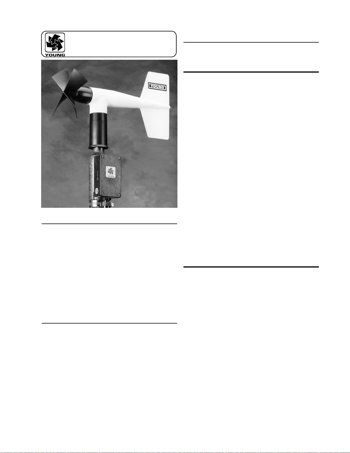
The Wind Monitor measures horizontal wind speed and direction.
Originally developed for ocean data buoy use, it is rugged and
corrosion resistant yet accurate and light weight. The main
housing, nose cone, propeller, and other internal parts are
injection molded U.V. stabilized plastic. Both the propeller and
vertical shafts use stainless steel precision grade ball bearings.
Bearings have light contacting teflon seals and are filled with a
low torque wide temperature range grease to help exclude
contamination and moisture.
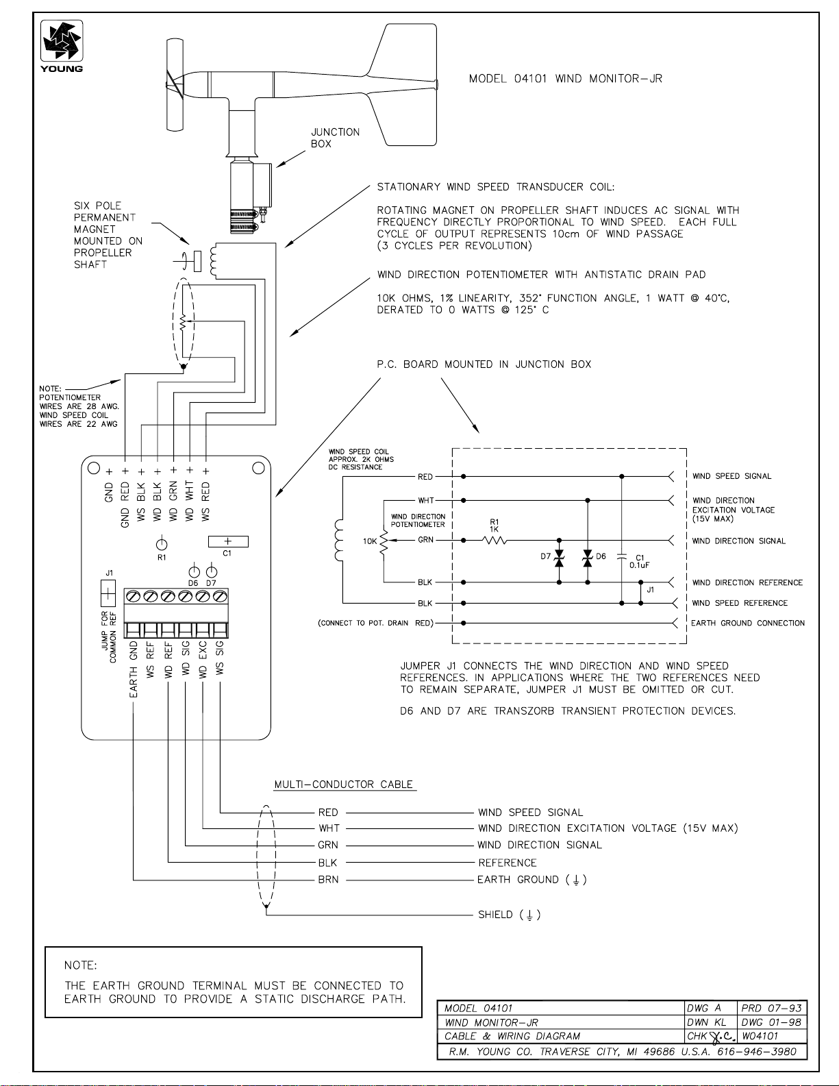
Propeller rotation produces an AC sine wave signal with frequency proportional to wind speed. This AC signal is induced in
a stationary coil by a six pole magnet mounted on the propeller
shaft. Three complete sine wave cycles are produced for each
propeller revolution.
Vane position is transmitted by a 10K ohm precision conductive
plastic potentiometer which requires a regulated excitation
voltage. With a constant voltage applied to the potentiometer, the
output signal is an analog voltage directly proportional to wind
direction angle.
The instrument mounts on standard one inch pipe, outside
diameter 34 mm (1.34"). An orientation ring is provided so the
instrument can be removed for maintenance and reinstalled
without loss of wind direction reference. Both mounting post
assembly and orientation ring are secured to the mounting pipe
by stainless steel band clamps. Electrical connections are made
in a junction box at the base. A variety of devices are available
for signal conditioning, display, and recording of wind speed and
direction.
INITIAL CHECKOUT
When the Wind Monitor is unpacked it should be checked
carefully for any signs of shipping damage. The instrument is
aligned, balanced and fully calibrated before shipment, however
it should be checked both mechanically and electrically before
installation. The vane and propeller should easily rotate 360°
without friction. Check vane balance by holding the instrument
base so the vane surface is horizontal. It should have near
neutral torque without any particular tendency to rotate. A slight
imbalance will not degrade performance.
Range 360° mechanical, 352° electrical
(8° open)
Sensor Balanced vane, 21 cm (8 in)
turning radius.
Damping Ratio 0.3
Delay Distance 0.8 m (2.6 ft) for 50% recovery
Threshold Sensitivity 1.7 m/s (3.8 mph) at 10° displacement
Transducer Precision conductive plastic poten-
tiometer, 10K ohm resistance (±20%),
1% linearity, life expectancy 50 mil-
lion revolutions, rated 1 watt at 40° C,
0 watts at 125° C
Transducer Excitation
Requirement Regulated DC voltage, 15 VDC max
Transducer Output Analog DC voltage proportional to
azimuth angle with regulated excita-
tion voltage applied across potenti-
ometer.
The potentiometer requires a stable DC excitation voltage. Do not
exceed 15 volts. When the potentiometer wiper is in the deadband
region, the output signal is “floating” and may show varying or
unpredictable values. To prevent false readings, signal conditioning electronics should clamp the signal to excitation or
reference level when this occurs. Note: Young signal condi-
tioning devices clamp the signal to excitation level. Avoid
a short circuit between the wind direction signal line and either
the excitation or reference lines. Damage to the potentiometer
may occur if a short circuit condition exists.
Before installation, connect the instrument to an indicator as
shown in the wiring diagram and check for proper wind speed
and wind direction values. Position the vane over a sheet of
paper with 30° or 45° crossmarkings to check vane alignment.
Page 1

INSTALLATION
Proper placement of the instrument is very important. Eddies from
trees, buildings, or other structures can greatly influence wind
speed and wind direction observations. To get meaningful data
for most applications locate the instrument well above or upwind
from obstructions. As a general rule, the air flow around a
structure is disturbed to twice the height of the structure upwind,
six times the height downwind, and up to twice the height of the
structure above ground. For some applications it may not be
practical or necessary to meet these requirements.
FAILURE TO PROPERLY GROUND THE
WIND MONITOR
MAY RESULT IN ERRONEOUS SIGNALS
OR TRANSDUCER DAMAGE.
Grounding the Wind Monitor is vitally important. Without proper
grounding, static electrical charge can build up during certain
atmospheric conditions and discharge through the transducers.
This discharge can cause erroneous signals or transducer
failure. To direct the discharge away from the transducers, the
mounting post assembly is made with a special antistatic plastic.
It is very important that the mounting post be connected to a good
earth ground. There are two ways this may be accomplished.
First, the Wind Monitor may be mounted on a metal pipe which is
connected to earth ground. The mounting pipe should not be
painted where the Wind Monitor is mounted. Towers or masts
set in concrete should be connected to one or more grounding
rods. If it is difficult to ground the mounting post in this manner,
the following method should be used. Inside the junction box the
terminal labeled EARTH GROUND is internally connected to the
antistatic mounting post. This terminal should be connected to an
earth ground (refer to wiring diagram).
To calibrate for wind direction, the following method can yield vane
calibration accuracies of ±5° or better if carefully done. Begin by
connecting the instrument to a signal conditioning circuit which
has some method of indicating wind direction value. This may be
a display which shows wind direction values in angular degrees or
simply a voltmeter monitoring the output. On a large sheet of paper
or cardboard, carefully draw lines, pie fashion, at 45° increments.
Mark these points with degree values; 0°, 45°, 90°.... Center the
instrument mounting base at the centerpoint of the markings with
the junction box facing South (180°). Visually align the vane with
each crossmarking and observe the indicator output. If the vane
position and indicator do not agree within 5°, it may be necessary
to adjust the potentiometer coupling inside the main housing.
Details for making this adjustment appear in the MAINTENANCE,
POTENTIOMETER REPLACEMENT outline, step 7.
It is important to note that while the sensor mechanically rotates
through 360°, the wind direction signal from the signal conditioning occurs at 352°. The signal conditioning electronics must be
adjusted accordingly. For example, in a circuit where 0 to 1.000
VDC represents 0° to 360°, the output must be adjusted for 0.978
VDC when the instrument is at 352°. (352°/360° X 1.000 volts =
0.978 volts)
Wind speed calibration is determined by propeller pitch and the
output characteristics of the transducer. Calibration formulas
showing propeller rpm and frequency output vs. wind speed are
included below. Standard accuracy is +/- 0.5m/sec. For greater
accuracy, the device must be individually calibrated in comparison with a wind speed standard. Contact the factory or your
supplier to schedule a NIST (National Institute of Standards &
Technology) traceable wind tunnel calibration in our facility.
Details on checking bearing torque, which affects wind speed
and direction threshold, appear in the following section.
Initial installation is most easily done with two people; one to
adjust the instrument position and the other to observe the
indicating device. After initial installation, the instrument can be
removed and returned to its mounting without realigning the vane
since the orientation ring preserves the wind direction reference. Install the Wind Monitor following these steps:
1. MOUNT WIND MONITOR
a) Place orientation ring on mounting post. Do Not tighten
band clamp yet.
b) Place Wind Monitor on mounting post. Do Not tighten
band clamp yet.
2. CONNECT SENSOR CABLE
a) Refer to wiring diagram located at back of manual.
3. ALIGN VANE
a) Connect instrument to an indicator.
b) Choose a known wind direction reference point on the
horizon.
c) Sighting down instrument centerline, point nose cone
at reference point on horizon.
d) While holding vane in position, slowly turn base until
indicator shows proper value.
e) Tighten mounting post band clamp.
f) Engage orientation ring indexing pin in notch at
instrument base.
g) Tighten orientation ring band clamp.
CALIBRATION
CALIBRATION FORMULAS
Model 04101 Wind Monitor-JR
WIND SPEED vs PROPELLER RPM
m/s = 0.00490 x rpm
knots = 0.00952 x rpm
mph = 0.01096 x rpm
km/h = 0.01764 x rpm
WIND SPEED vs OUTPUT FREQUENCY
m/s = 0.0980 x Hz
knots = 0.1904 x Hz
mph = 0.2192 x Hz
km/h = 0.3528 x Hz
MAINTENANCE
Given proper care, the Wind Monitor should provide years of
service. The only components likely to need replacement due to
normal wear are the precision ball bearings and the wind
direction potentiometer. Only a qualified instrument technician
should perform the replacement. If service facilities are not
available, return the instrument to the company. Refer to the
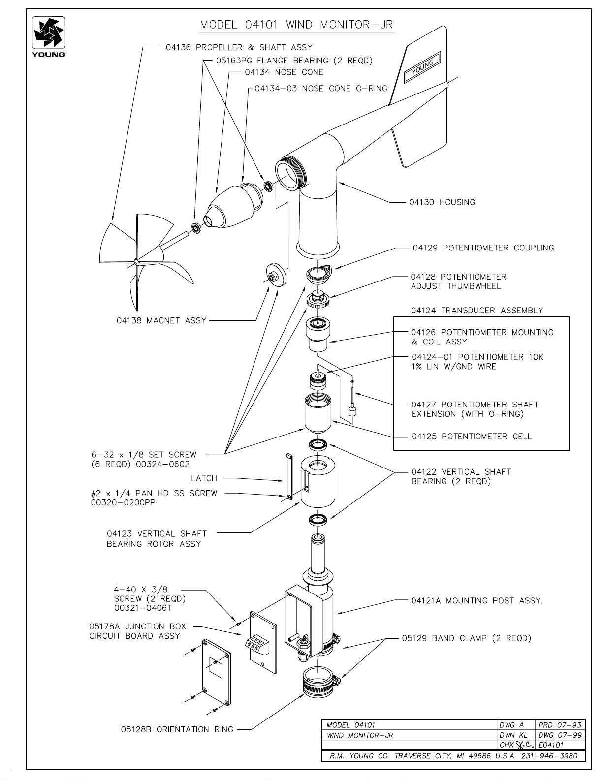
drawings to become familiar with part names and locations. The
asterisk * which appears in the following outlines is a reminder
that maximum torque on all set screws is 80 oz-in.
The Wind Monitor is fully calibrated before shipment and should
require no adjustments. Recalibration may be necessary after
some maintenance operations. Periodic calibration checks are
desirable and may be necessary where the instrument is used
in programs which require auditing of sensor performance.
Page 2

POTENTIOMETER REPLACEMENT
The potentiometer has a life expectancy of fifty million revolutions. As it becomes worn, the element may begin to produce
noisy signals or become nonlinear. When signal noise or nonlinearity becomes unacceptable, replace the potentiometer. Refer
to exploded view drawing and proceed as follows:
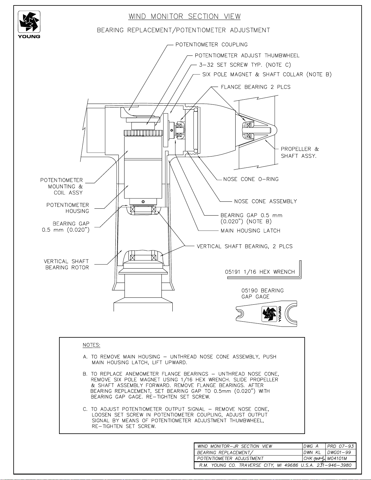
1. REMOVE MAIN HOUSING
a) Unscrew nose cone from main housing.
b) Gently push main housing latch, visible inside front
housing.
c) While pushing latch, lift main housing up and remove it from
vertical shaft bearing rotor.
2. UNSOLDER TRANSDUCER WIRE
a) Slide junction box cover up, exposing circuit board.
b) Remove screws holding circuit board.
c) Unsolder three potentiometer wires (white, green, black),
two wind speed coil wires (red, black) and earth ground
wire (gray) from board.
3. REMOVE POTENTIOMETER
a) Loosen set screw on potentiometer coupling and
remove it from potentiometer adjust thumbwheel.
b) Loosen set screw on potentiometer adjust thumbwheel
and remove it from potentiometer shaft extension.
c) Loosen two set screws at base of transducer assembly
and remove assembly from vertical shaft.
d) Unscrew potentiometer housing from potentiometer
mounting & coil assembly.
e) Push potentiometer out of potentiometer mounting &
coil assembly by applying firm but gentle pressure on
potentiometer shaft extension. Set o-ring aside for
later use.
f) Loosen set screw on potentiometer shaft extension
and remove it from potentiometer shaft.
4. INSTALL NEW POTENTIOMETER
a) Place potentiometer shaft extension with o-ring on new
potentiometer (Gap 0.040") and tighten set screw*.
Regrease o-ring if necessary.
b) Push new potentiometer into potentiometer mounting & coil
assembly.
c) Feed potentiometer and coil wires through hole in bottom
of potentiometer housing.
d) Screw potentiometer housing onto potentiometer mounting
& coil assembly.
e) Gently pull transducer wires through bottom of
potentiometer housing to take up any slack. Apply a
small amount of silicone sealant around hole.
f) Install transducer assembly on vertical shaft allowing
0.5 mm (0.020") clearance from vertical bearing. Tighten
set screws* at bottom of transducer assembly.
g) Place potentiometer adjust thumbwheel on
potentiometer shaft extension and tighten set screw*.
h) Place potentiometer coupling on potentiometer adjust
thumbwheel. Do not tighten set screw yet.
5. RECONNECT TRANSDUCER WIRES
a) Using needle-nose pliers or a paper clip bent to form a
small hook, gently pull transducer wires through hole
in junction box.
b) Solder wires to circuit board according to wiring diagram.
Observe color code.
c) Secure circuit board in junction box using two screws
removed in step 2b. Do not overtighten.
6. REPLACE MAIN HOUSING
a) Place main housing over vertical shaft bearing rotor.
Be careful to align indexing key and channel in these
two assemblies.
b) Place main housing over vertical shaft bearing rotor
until potentiometer coupling is near top of main housing.
c) Turn potentiometer adjust thumbwheel until
potentiometer coupling is oriented to engage ridge in
top of main housing. Set screw on potentiometer
coupling should be facing the front opening.
d) With potentiometer coupling properly oriented,
continue pushing main housing onto vertical shaft
bearing rotor until main housing latch locks into position
with a “click”.
7. ALIGN VANE
a) Connect excitation voltage and signal conditioning
electronics to terminal strip according to wiring
diagram.
b) With mounting post held in position so junction box is
facing due south, orient vane to a known angular
reference. Details appear in CALIBRATION section.
c) Reach in through front of main housing and turn
potentiometer adjust thumbwheel until signal conditioning
system indicates proper value.
d) Tighten set screw* on potentiometer coupling.
8. REPLACE NOSE CONE
a) Screw nose cone into main housing firmly, using only
hand pressure. Be certain threads are properly
engaged to avoid cross-threading.
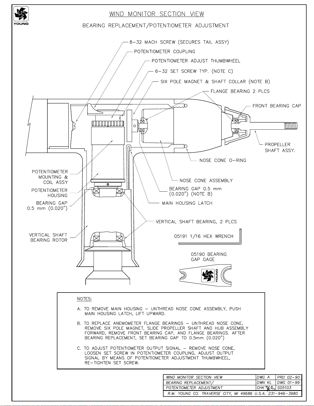
FLANGE BEARING REPLACEMENT
If anemometer bearings become noisy or wind speed threshold
increases above an acceptable level, bearings may need replacement. A rough check of anemometer bearing condition can
be performed by adding an ordinary paper clip (0.5 gm) to the tip
of a propeller blade. Turn the blade with the paper clip to the
"three o'clock" or "nine o'clock" position and gently release it.
Failure to rotate due to the weight of the paper clip indicates
anemometer bearings need replacement. Repeat this test at
different positions to check full bearing rotation. If needed,
bearings are replaced as follows.
1. REMOVE OLD BEARINGS
a) Unscrew nose cone.
b) Loosen set screw on magnet shaft collar and
remove magnet.
c) Slide propeller shaft out of nose cone assembly.
d) Remove both front and rear bearings from nose cone
assembly. Insert edge of a pocket knife under bearing
flange and lift it out.
2. INSTALL NEW BEARINGS
a) Insert new front and rear bearings into nose cone.
b) Carefully slide propeller shaft thru bearings.
c) Replace magnet on propeller shaft allowing 0.5 mm
(0.020") clearance from rear bearing.
d) Tighten set screw* on magnet shaft collar.
e) Screw nose cone into main housing until seated. Be
certain threads are properly engaged to avoid
cross-threading.
*Max set screw torque 80 oz-in
Page 3
VERTICAL SHAFT BEARING REPLACEMENT
Vertical shaft bearings are much larger than the anemometer
bearings. Ordinarily, these bearings will last about twice as long as
the anemometer bearings. Check bearing condition holding the
instrument with the vane horizontal and placing a 3 gm weight near
the aft edge of the fin. A U.S. penny weighs about 3 gm and is
convenient for this check. Failure to rotate downward indicates the
vertical bearings need replacement. Repeat this test at different
positions to check full bearing rotation.
Since this procedure is similar to POTENTIOMETER REPLACEMENT, only the major steps are listed here.
1. REMOVE MAIN HOUSING
2. UNSOLDER TRANSDUCER WIRES AND REMOVE
TRANSDUCER ASSEMBLY
Loosen set screws at base of transducer assembly and
remove entire assembly from vertical shaft.
3. REMOVE VERTICAL SHAFT BEARING ROTOR by sliding
it upward off vertical shaft.
4. REMOVE OLD VERTICAL BEARINGS AND INSTALL NEW
BEARINGS. When inserting new bearings, be careful not
to apply pressure to bearing shields.
5. REPLACE VERTICAL SHAFT BEARING ROTOR.
6. REPLACE TRANSDUCER & RECONNECT WIRES
7. REPLACE MAIN HOUSING
8. ALIGN VANE
9. REPLACE NOSE CONE
WARRANTY
This product is warranted to be free of defects in materials and construction for a period of 12 months from date of initial purchase. Liability is limited to repair or replacement of defective item. A copy of the
warranty policy may be obtained from R. M. Young Company.
Declaration of Conformity
Application of Council Directives:
89/336/EEC
Standards to which Conformity is Declared:
EN 50082-1 (IEC 801-2, 3, 4)
Manufacturer's Name and Address:
R. M. Young Company
Traverse City, MI, 49686, USA
Importer's Name and Address:
See Shipper or Invoice
Type of Equipment:
Meteorological Instruments
Model Number / Year of Manufacture:
04101/1996
I, the undersigned, hereby declare that the equipment
specified conforms to the above Directives and Standards.
Date / Place:
Traverse City, Michigan, USA February 19, 1996
David Poinsett
R & D Manager, R. M. Young Company
CE COMPLIANCE
This product has been tested and shown to comply with European CE
requirements for the EMC Directive. Please note that shielded cable
must be used.
Page 4

MODEL 05103
WIND MONITOR
NOVEMBER 2001
MANUAL PN 05103-90
R. M. YOUNG COMPANY
2801 AERO PARK DRIVE, TRAVERSE CITY, MICHIGAN 49686, USA
TEL: (231) 946-3980 FAX: (231) 946-4772

MODEL 05103
WIND MONITOR
WIND SPEED SPECIFICATION SUMMARY
GENERAL
Operating Temperature: -50 to 50°C (-58 to 122°F)
INTRODUCTION
The Wind Monitor measures horizontal wind speed and direction.
Originally developed for ocean data buoy use, it is rugged and
corrosion resistant yet accurate and light weight. The main
housing, nose cone, propeller, and other internal parts are
injection molded U.V. stabilized plastic. Both the propeller and
vertical shafts use stainless steel precision grade ball bearings.
Bearings have light contacting teflon seals and are filled with a
wide temperature range grease to help exclude contamination
and moisture.
Propeller rotation produces an AC sine wave signal with frequency proportional to wind speed. This AC signal is induced in
a stationary coil by a six pole magnet mounted on the propeller
shaft. Three complete sine wave cycles are produced for each
propeller revolution.
Vane position is transmitted by a 10K ohm precision conductive
plastic potentiometer which requires a regulated excitation
voltage. With a constant voltage applied to the potentiometer, the
output signal is an analog voltage directly proportional to wind
direction angle.
Range 0 to 60 m/s (130 mph), gust survival
100 m/s (220 mph)
Sensor 18 cm diameter 4-blade helicoid
propeller molded of polypropylene
Pitch 29.4 cm air passage per revolution
Distance Constant 2.7 m (8.9 ft.) for 63% recovery
Threshold Sensitivity 1.0 m/s (2.2 mph)
Transducer Centrally mounted stationary coil,
2K Ohm nominal DC resistance
Transducer Output AC sine wave signal induced by
rotating magnet on propeller shaft.
80 mV p-p at 100 rpm. 8.0 V p-p at
10,000 rpm.
Output Frequency 3 cycles per propeller revolution
(0.0980 m/s per Hz)
WIND DIRECTION (AZIMUTH) SPECIFICATION SUMMARY
Range 360° mechanical, 355° electrical
(5° open)
Sensor Balanced vane, 38 cm (15 in)
turning radius.
Damping Ratio 0.3
Delay Distance 1.3 m (4.3 ft) for 50% recovery
Threshold Sensitivity 1.1 m/s (2.5 mph) at 10° displacement
Damped Natural
Wavelength 7.4 m (24.3 ft)
Undamped Natural
Wavelength 7.2 m (23.6 ft)
Transducer Precision conductive plastic potetio-
meter, 10K ohm resistance (±20%),
0.25% linearity, life expectancy 50
million revolutions, rated 1 watt at
40° C, 0 watts at 125° C
Transducer Excitation
Requirement Regulated DC voltage, 15 VDC max
Transducer Output Analog DC voltage proportional to
azimuth angle with regulated excitation
voltage applied across potentiometer.
The instrument mounts on standard one inch pipe, outside
diameter 34 mm (1.34"). An orientation ring is provided so the
instrument can be removed for maintenance and reinstalled
without loss of wind direction reference. Both the mounting post
assembly and the orientation ring are secured to the mounting
pipe by stainless steel band clamps. Electrical connections are
made in a junction box at the base. A variety of devices are
available for signal conditioning, display, and recording of wind
speed and direction.
INITIAL CHECKOUT
When the Wind Monitor is unpacked it should be checked
carefully for any signs of shipping damage.
Remove the plastic nut on the propeller shaft. Install the propeller
on the shaft so the serial number on the propeller faces forward
(into the wind). Engage the propeller into the molded ribs on the
propeller shaft hub. The instrument is aligned, balanced and fully
calibrated before shipment, however, it should be checked both
mechanically and electrically before installation. The vane and
propeller should easily rotate 360° without friction. Check vane
balance by holding the instrument base so the vane surface is
horizontal. It should have near neutral torque without any
particular tendency to rotate. A slight imbalance will not degrade
performance.
The potentiometer requires a stable DC excitation voltage. Do not
exceed 15 volts. When the potentiometer wiper is in the 5°
deadband region, the output signal is "floating" and may show
varying or unpredictable values. To prevent false readings,
signal conditioning electronics should clamp the signal to excitation or reference level when this occurs. NOTE: Young signal
conditioning devices clamp the signal to excitation level.
Avoid a short circuit between the wind direction signal line and
either the excitation or reference lines. Although there is a 1K
ohm current limiting resistor in series with the wiper for protection, damage to the potentiometer may occur if a short circuit
condition exists.
Page 1

Before installation, connect the instrument to an indicator as
shown in the wiring diagram and check for proper wind speed
and wind direction values. To check wind speed, temporarily
remove the propeller and connect the shaft to an Anemometer
Drive. Details appear in the CALIBRATION section of this manual.
INSTALLATION
CALIBRATION
The Wind Monitor is fully calibrated before shipment and should
require no adjustments. Recalibration may be necessary after
some maintenance operations. Periodic calibration checks are
desirable and may be necessary where the instrument is used
in programs which require auditing of sensor performance.
Proper placement of the instrument is very important. Eddies from
trees, buildings, or other structures can greatly influence wind
speed and wind direction observations. To get meaningful data
for most applications locate the instrument well above or upwind
from obstructions. As a general rule, the air flow around a
structure is disturbed to twice the height of the structure upwind,
six times the height downwind, and up to twice the height of the
structure above ground. For some applications it may not be
practical or necessary to meet these requirements.
FAILURE TO PROPERLY GROUND THE WIND MONITOR
MAY RESULT IN ERRONEOUS SIGNALS
OR TRANSDUCER DAMAGE.
Grounding the Wind Monitor is vitally important. Without proper
grounding, static electrical charge can build up during certain
atmospheric conditions and discharge through the transducers.
This discharge can cause erroneous signals or transducer
failure. To direct the discharge away from the transducers, the
mounting post assembly is made with a special antistatic plastic.
It is very important that the mounting post be connected to a good
earth ground. There are two ways this may be accomplished.
First, the Wind Monitor may be mounted on a metal pipe which is
connected to earth ground. The mounting pipe should not be
painted where the Wind Monitor is mounted. Towers or masts set
in concrete should be connected to one or more grounding rods.
If it is difficult to ground the mounting post in this manner, the
following method should be used. Inside the junction box the
terminal labeled EARTH GND is internally connected to the
antistatic mounting post. This terminal should be connected to an
earth ground (Refer to wiring diagram).
Initial installation is most easily done with two people; one to
adjust the instrument position and the other to observe the
indicating device. After initial installation, the instrument can be
removed and returned to its mounting without realigning the vane
since the orientation ring preserves the wind direction reference. Install the Wind Monitor following these steps:
Accurate wind direction calibration requires a Model 18112
Vane Angle Bench Stand. Begin by connecting the instrument
to a signal conditioning circuit which has some method of
indicating wind direction value. This may be a display which
shows wind direction values in angular degrees or simply a
voltmeter monitoring the output. Orient the base so the junction
box faces due south. Visually align the vane with the
crossmarkings and observe the indicator output. If the vane
position and indicator do not agree within 5°, adjust the potentiometer coupling inside the main housing. Details for making
this adjustment appear in the MAINTENANCE, POTENTIOMETER
REPLACEMENT, outline, step 7.
It is important to note that, while the sensor mechanically rotates
through 360°, the full scale wind direction signal from the signal
conditioning occurs at 355°. The signal conditioning electronics
must be adjusted accordingly. For example, in a circuit where 0
to 1.000 VDC represents 0° to 360°, the output must be adjusted
for 0.986 VDC when the instrument is at 355°. (355°/360° X 1.000
volts = 0.986 volts)
Wind speed calibration is determined by propeller pitch and the
output characteristics of the transducer. Calibration formulas
showing wind speed vs. propeller rpm and output frequency are
included below. Standard accuracy is ± 0.3 m/s (0.6mph). For
greater accuracy, the sensor must be individually calibrated in
comparison with a wind speed standard. Contact the factory or
your supplier to schedule a NIST (National Institute of Standards
& Technology) traceable wind tunnel calibration in our facility.
To calibrate wind system electronics using a signal from the
instrument, temporarily remove the propeller and connect an
Anemometer Drive to the propeller shaft. Apply the appropriate
calibration formula to the calibrating motor rpm and adjust the
electronics for the proper value. For example, with the propeller
shaft turning at 3600 rpm adjust an indicator to display 17.6 meters
per second [3600 rpm X 0.00490 (m/s)/rpm =17.6 m/s]
Details on checking bearing torque, which affects wind speed and
direction threshold, appear in the following section.
1. MOUNT WIND MONITOR
a) Place orientation ring on mounting post. Do Not tighten band
clamp yet.
b) Place Wind Monitor on mounting post. Do Not tighten band
clamp yet.
2. CONNECT SENSOR CABLE
a) Refer to wiring diagram located at back of manual.
3. ALIGN VANE
a) Connect instrument to an indicator.
b) Choose a known wind direction reference point on the
horizon.
c) Sighting down instrument centerline, point nose cone at
reference point on horizon.
d) While holding vane in position, slowly turn base until
indicator shows proper value.
e) Tighten mounting post band clamp.
f) Engage orientation ring indexing pin in notch at instrument
base.
g) Tighten orientation ring band clamp.
CALIBRATION FORMULAS
Model 05103 Wind Monitor w /08234 Propeller
WIND SPEED vs PROPELLER RPM
m/s = 0.00490 x rpm
knots = 0.00952 x rpm
mph = 0.01096 x rpm
km/h = 0.01764 x rpm
WIND SPEED vs OUTPUT FREQUENCY
m/s = 0.0980 x Hz
knots = 0.1904 x Hz
mph = 0.2192 x Hz
km/h = 0.3528 x Hz
Page 2

MAINTENANCE
h) Place potentiometer coupling on potentiometer
adjust thumbwheel. Do Not tighten set screw yet.
Given proper care, the Wind Monitor should provide years of
service. The only components likely to need replacement due to
normal wear are the precision ball bearings and the wind
direction potentiometer. Only a qualified instrument technician
should perform the replacement. If service facilities are not
available, return the instrument to the company. Refer to the
drawings to become familiar with part names and locations. The
asterisk * which appears in the following outlines is a reminder
that maximum torque on all set screws is 80 oz-in.
POTENTIOMETER REPLACEMENT
The potentiometer has a life expectancy of fifty million revolutions. As it becomes worn, the element may begin to produce
noisy signals or become nonlinear. When signal noise or nonlinearity becomes unacceptable, replace the potentiometer. Refer
to exploded view drawing and proceed as follows:
1. REMOVE MAIN HOUSING
a) Unscrew nose cone from main housing. Set o-ring aside
for later use.
b) Gently push main housing latch.
c) While pushing latch, lift main housing up and remove it from
vertical shaft bearing rotor.
2. UNSOLDER TRANSDUCER WIRE
a) Remove junction box cover, exposing circuit board.
b) Remove screws holding circuit board.
c) Unsolder three potentiometer wires (white, green, black),
two wind speed coil wires (red, black) and earth ground
wire (red) from board.
3. REMOVE POTENTIOMETER
a) Loosen set screw on potentiometer coupling and remove
it from potentiometer adjust thumbwheel.
b) Loosen set screw on potentiometer adjust thumbwheel
and remove it from potentiometer shaft extension.
c) Loosen two set screws at base of transducer assembly
and remove assembly from vertical shaft.
d) Unscrew potentiometer housing from potentiometer
mounting & coil assembly.
e) Push potentiometer out of potentiometer mounting & coil
assembly by applying firm but gentle pressure on potentiometer shaft extension. Set o-ring aside for later use.
f ) Loosen set screw on potentiometer shaft extension
and remove it from potentiometer shaft.
4. INSTALL NEW POTENTIOMETER
a) Place potentiometer shaft extension with o-ring on n e w
potentiometer (Gap 0.040") and tighten set screw*.
Regrease o-ring if necessary.
b) Push new potentiometer into potentiometer mounting & coil
assembly.
c) Feed potentiometer and coil wires through hole in
bottom of potentiometer housing.
d) Screw potentiometer housing onto potentiometer
mounting & coil assembly.
e) Gently pull transducer wires through bottom of
potentiometer housing to take up any slack. Apply a
small amount of silicone sealant around hole.
f ) Install transducer assembly on vertical shaft allowing
0.5 mm (0.020") clearance from vertical bearing.
Tighten set screws* at bottom of transducer assembly.
g) Place potentiometer adjust thumbwheel on potentiometer
shaft extension and tighten set screw*.
5. RECONNECT TRANSDUCER WIRES
a) Using needle-nose pliers or a paper clip bent to form a small
hook, gently pull transducer wires through hole in junction
box.
b) Solder wires to circuit board according to wiring diagram.
Observe color code.
c) Secure circuit board in junction box using two screws
removed in step 2b. Do not overtighten.
6. REPLACE MAIN HOUSING
a) Place main housing over vertical shaft bearing rotor. Be
careful to align indexing key and channel in these two
assemblies.
b) Place main housing over vertical shaft bearing rotor until
potentiometer coupling is near top of main housing.
c) Turn potentiometer adjust thumbwheel until potentiometer
coupling is oriented to engage ridge in top of main housing.
Set screw on potentiometer coupling should be facing the
front opening.
d) With potentiometer coupling properly oriented, continue
pushing main housing onto vertical shaft bearing rotor until
main housing latch locks into position with a “click”.
7. ALIGN VANE
a) Connect excitation voltage and signal conditioning elec-
tronics to terminal strip according to wiring diagram.
b) With mounting post held in position so junction box is facing
due south, orient vane to a known angular reference.
Details appear in CALIBRATION section.
c) Reach in through front of main housing and turn potentiom-
eter adjust thumbwheel until signal conditioning system
indicates proper value.
d) Tighten set screw* on potentiometer coupling.
8. REPLACE NOSE CONE
a) Screw nose cone into main housing until o-ring seal is
seated. Be certain threads are properly engaged to avoid
cross-threading.
FLANGE BEARING REPLACEMENT
If anemometer bearings become noisy or wind speed threshold
increases above an acceptable level, bearings may need replacement. Check anemometer bearing condition using a Model
18310 Propeller Torque Disc. If needed, bearings are replaced
as follows.
1. REMOVE OLD BEARINGS
a) Unscrew nose cone. Set o-ring aside for later use.
b) Loosen set screw on magnet shaft collar and remove
magnet.
c) Slide propeller shaft out of nose cone assembly.
d) Remove front bearing cap which covers front bearing.
e) Remove both front and rear bearings from nose cone
assembly. Insert edge of a pocket knife under bearing
flange and lift it out.
2. INSTALL NEW BEARINGS
a) Insert new front and rear bearings into nose cone.
b) Replace front bearing cap.
c) Carefully slide propeller shaft thru bearings.
d) Place magnet on propeller shaft allowing 0.5 mm
(0.020") clearance from rear bearing.
e) Tighten set screw* on magnet shaft collar.
f ) Screw nose cone into main housing until o-ring seal
is seated. Be certain threads are properly engaged to
avoid cross-threading.
*Max set screw torque 80 oz-in
Page 3

VERTICAL SHAFT BEARING REPLACEMENT
Vertical shaft bearings are much larger than the anemometer
bearings. Ordinarily, these bearings require replacement less
frequently than anemometer bearings. Check bearing condition
using a Model 18331 Vane Torque Gauge.
Since this procedure is similar to POTENTIOMETER REPLACEMENT, only the major steps are listed here.
1. REMOVE MAIN HOUSING
2. UNSOLDER TRANSDUCER WIRES AND REMOVE
TRANSDUCER ASSEMBLY
Loosen set screws at base of transducer assembly and
remove entire assembly from vertical shaft.
3. REMOVE VERTICAL SHAFT BEARING ROTOR by sliding it
upward off vertical shaft.
4. REMOVE OLD VERTICAL BEARINGS AND INSTALL NEW
BEARINGS. When inserting new bearings, be careful not
to apply pressure to bearing shields.
5. REPLACE VERTICAL SHAFT BEARING ROTOR.
6. REPLACE TRANSDUCER & RECONNECT WIRES
7. REPLACE MAIN HOUSING
8. ALIGN VANE
9. REPLACE NOSE CONE
Declaration of Conformity
Application of Council Directives:
89/336/EEC
Standards to which Conformity is Declared:
EN 50082-1(IEC 801-2,3,4)
Manufacturer's Name and Address:
R. M. Young Company
Traverse City, MI, 49686, USA
Importer's Name and Address:
See Shipper or Invoice
Type of Equipment:
Meteorological Instruments
Model Number / Year of Manufacture:
05103/1996
I, the undersigned, hereby declare that the equipment
specified conforms to the above Directives and
Standards.
Place /Date:
Traverse City, Michigan, USA /February 19, 1996
WARRANTY
This product is warranted to be free of defects in materials and
construction for a period of 12 months from date of initial purchase.
Liability is limited to repair or replacement of defective item. A copy
of the warranty policy may be obtained from R. M. Young Company.
CE COMPLIANCE
This product has been tested and shown to comply with European CE requirements for the EMC Directive (see Declaration of
Conformity below). Please note that shielded cable must be used.
David Poinsett
R & D Manager, R. M. Young Company
Page 4


Calibration Accessories
Model 18802
Anemometer Drive
Model 18112
Vane Angle Bench Stand
Model 18331 Vane Torque Gauge
Model 18310
Propeller Torque Disc
Model 18212
Vane Angle Fixture-Tower Mount
Model 18301
Vane Alignment Rod

YOUNG
Calibration Accessories
Model 18802 Anemometer Drive provides a convenient and accurate way to rotate an anemometer shaft at
a known rate. The motor may be set to rotate clockwise or counter-clockwise at any rate between 200 and
15,000 RPM in 100 RPM increments. The LCD display is referenced to an accurate and stable quartz timebase.
For completely portable operation, the unit can be operated on internal batteries. For extended operation, an
AC wall adapter is included.
Model 18811 Anemometer Drive is identical to Model 18802 except the drive motor incorporates a
gear reducer for operation in the range of 20 to 990 RPM in 10 RPM increments. The lower range
is recommended for cup anemometer calibration.
Model 18112 Vane Angle Bench Stand is used for benchtop wind direction calibration of the Wind Monitor
family of sensors. The mounting post engages the direction orientation notch on the Wind Monitor. An easy to
read pointer indicates 0 to 360 degrees with 1/2 degree resolution.
Model 18212 Vane Angle Fixture - Tower Mount similar to the Model 18112, the tower mount feature allows use
on the tower as well as the bench top. The fixture is temporarily placed on the tower between the Wind Monitor
and its tower mounting. Index keys and notches are engaged to preserve direction reference.
Model 18310 Propeller Torque Disc checks anemometer bearing torque with 0.1 gm/cm resolution. The disc temporarily replaces the propeller for torque measurement or simple yet accurate pass/fail
checks. Charts included with the unit relate torque to propeller threshold with limits for acceptable
bearing performance.
Model 18312 Cup-Wheel Torque Disc checks cup anemometer bearing torque.
Model 18331 Vane Torque Gauge checks vane bearing torque of the Wind Monitor family sensors. Slip the
fixture over the main housing and make simple yet accurate vane torque measurements. Charts relating vane
torque to vane threshold provide limits for acceptable bearing performance.
Model 18301 Vane Alignment Rod helps align the vane of a wind sensor to a known direction reference during
installation. The base of the device has an index key that engages the direction orientation notch in the sensor
allowing the sensor to be removed without losing wind direction reference.
Specifications
MODEL 18802 ANEMOMETER DRIVE
(Replaces 18801)
Range:
200 to 15,000 RPM in 100 RPM increments
Rotation:
Clockwise or Counter-Clockwise
Display Resolution:
1 RPM
Quartz Timebase Reference:
0.1 RPM
Power Requirement:
2x9 V (alkaline or lithium) batteries
115 VAC wall adapter included
(230 VAC – add suffix H)
MODEL 18811 ANEMOMETER DRIVE
(Replaces 18810)
Range:
20 to 990 RPM in 10 RPM increments
Display Resolution:
0.1 RPM
MODEL 18112, 18212 VANE ANGLE
CALIBRATION DEVICES
Range:
0 to 360 degrees
Resolution:
0.5 degree
Ordering Information MODEL
ANEMOMETER DRIVE 200 to 15,000 RPM .............................................. 18802
ANEMOMETER DRIVE 20 TO 990 RPM .................................................. 18811
230V / 50-60 HZ INPUT POWER ................................................... ADD SUFFIX “H”
VANE ANGLE BENCH STAND .......................................................... 18112
VANE ANGLE FIXTURE - TOWER MOUNT ........................................... 18212
PROPELLER TORQUE DISC............................................................ 18310
CUP-WHEEL TORQUE DISC ........................................................... 18312
VANE TORQUE GAUGE ................................................................. 18331
VANE ALIGNMENT ROD ................................................................ 18301
R.M. YOUNG COMPANY
2801 Aero Park Drive
Traverse City, Michigan 49686 USA
TEL: (231) 946-3980 FAX: (231) 946-4772
E-mail: met.sales@youngusa.com
Web Site: www.youngusa.com
MODEL 18310, 18312 TORQUE DISC DEVICES
Range:
0 to 5.4 gm-cm
Resolution:
0.1 gm-cm
MODEL 18331 VANE TORQUE GAUGE
Range:
0 to 50 gm-cm
Resolution:
5 gm-cm
Specifications subject to change without notice.
Copyright © 2000 R.M. Young Company, Printed in U.S.A . 11/00
 Loading...