

Page 1

Model
H-339
SDI-12 “TimeKeeper”
GPS Time / Location Sensor
Owner's Manual
Revision 1.10
Page 2

Table of Contents
User Agreement/WATERLOG Warranty ........................................® W-1
Chapter 1 Operation
Introduction ................................................................ 1-1
Installation.................................................................. 1-1
GPS Module Connections...................................................... 1-2
SDI-12 Connections........................................................... 1-3
First Time Acquire............................................................ 1-4
Operation................................................................... 1-5
Programming the H-339........................................................ 1-5
Programming the Data Recorder................................................. 1-5
Position Data................................................................ 1-6
Time Accuracy............................................................... 1-7
Words of Caution............................................................. 1-7
Chapter 2 SDI-12 Command and Response Protocol
SDI-12 Command and Response Protocol ........................................ 2-1
Measure Command. ......................................................... 2-2
Concurrent Measurement Command . ........................................... 2-3
Send Data Command . ....................................................... 2-4
Initiate Verify Command . .................................................... 2-5
Send Identification Command . ................................................ 2-7
Send Acknowledge Command................................................... 2-8
Change Sensor Address........................................................ 2-8
Appendix A - Specifications .................................................. A-1
Appendix B - GPS Utility Software ............................................. B-1
Overview...................................................................B-1
Functionality. ...............................................................B-1
Page 3

User Agreement/
WATERLOG Warranty
1. NATURE OF THE PRODUCT
This agreement accompanies a pressure measuring system comprising micro-coded circuitry and
other electronic equipment sealed in an enclosed housing, and packaged together with written
instructional materials. The packaged electronic circuitry and instructional materials herein are
collectively referred to as the “PRODUCT.” The PRODUCT is made available from DESIGN
ANALYSIS ASSOCIATES, INC., of 75 West 100 South, Logan, Utah 84321 (hereinafter referred
to as “DESIGN ANALYSIS”), and contains information and embodies technology that is
confidential and proprietary to DESIGN ANALYSIS, and the availability and use of the PRODUCT
is extended to you, the USER, solely on the basis of the terms of agreement which follow.
2. ACKNOWLEDGMENTS BY USER
Opening the package which encloses the accompanying PRODUCT indicates your acceptance of the
terms and conditions of this agreement and constitutes an acknowledgment by you of the confidential
and proprietary nature of the rights of DESIGN ANALYSIS in the PRODUCT.
3. DUTIES OF YOU, THE USER
®
In consideration for the access to and use of the PRODUCT extended to you by DESIGN
ANALYSIS and to protect the confidential and proprietary information of DESIGN ANALYSIS,
USER agrees as follows:
(a) USER agrees that they will not open the sealed housing of the PRODUCT, and that they
will take all necessary precautions to prevent their employees, agents, sub-contractors
and resellers from doing so.
(b) USER agrees that they will not remove from the exterior of the housing of the
PRODUCT any warnings against opening or notices of proprietary interest placed
thereon by DESIGN ANALYSIS, and that they will take all necessary precautions to
prevent their employees, agents, sub-contractors, and resellers form removing such
markings therefrom.
(c) USER agrees to treat the PRODUCT with the same degree of care as USER exercises
in relation to their own confidential and proprietary information.
(d) USER agrees to return the PRODUCT to DESIGN ANALYSIS if and when the
PRODUCT is deemed to be no longer of use. In return therefore, USER will receive
from DESIGN ANALYSIS a redemption fee of $10.00.
H-339 User Agreement/WATERLOG Warranty W-1
®
Page 4

4. TERM
USER may enjoy these rights only as long as their possession of the PRODUCT shall continue to
be rightful. These rights will cease if the PRODUCT is returned to DESIGN ANALYSIS under the
terms of any redemption offer, warranty, or money-back guarantee, or if USER transfers the
PRODUCT to another party on terms inconsistent with this agreement.
5. LIMITED WARRANTY
(a) What is Covered
DESIGN ANALYSIS warrants that for a period of twenty four months from the time of
purchase the functions to be performed by the PRODUCT will be substantially in
compliance with USER documentation. DESIGN ANALYSIS also warrants that the
PRODUCT will be free from defects in materials and workmanship for a period of
TWO YEARS from the date of purchase.
(b) What USER Must Do
If the product fails to satisfy the above warranty, USER must notify DESIGN
ANALYSIS in writing within the applicable period specified above and reasonably
cooperate with the directions they received from DESIGN ANALYSIS.
(c) What DESIGN ANALYSIS Will Do
DESIGN ANALYSIS will repair the PRODUCT or will endeavor to provide a
replacement of same within a reasonable period of time. In the event that DESIGN
ANALYSIS is unable to make the necessary repairs or replacement within a reasonable
period of time, the original purchase price will be refunded upon the return of the
PRODUCT to DESIGN ANALYSIS.
(d) Limitations
(i) THIS LIMITED WARRANTY IS VOIDED WHERE THE SEALED HOUSING
OF THE PRODUCT HAS BEEN OPENED.
(ii) THE ENTIRE REMEDY FOR BREACH OF THIS LIMITED WARRANTY
SHALL BE LIMITED TO REPLACEMENT OF THE DEFECTIVE PRODUCT
OR REFUNDING OF THE PURCHASE PRICE, AS SET FORTH ABOVE. IN
NO EVENT WILL THE LIABILITY OF DESIGN ANALYSIS TO USER OR
TO ANY OTHER PARTY EXCEED THE ORIGINAL PURCHASE PRICE OF
THE PRODUCT, REGARDLESS OF THE FORM OF THE CLAIM.
W-2 User Agreement/WATERLOG Warranty H-339
®
Page 5

(iii) EXCEPT FOR THE EXPRESS WARRANTIES ABOVE, DESIGN ANALYSIS
SPECIFICALLY DISCLAIMS ALL OTHER WARRANTIES, INCLUDING,
WITHOUT LIMITATION, ALL IMPLIED WARRANTIES OF
MERCHANTABILITY AND FITNESS FOR A PARTICULAR PURPOSE.
(iv) UNDER NO CIRCUMSTANCES WILL DESIGN ANALYSIS BE LIABLE FOR
SPECIAL, INCIDENTAL, CONSEQUENTIAL, INDIRECT, OR ANY OTHER
DAMAGES OR CLAIMS ARISING FROM THE USE OF THIS PRODUCT,
THIS INCLUDES LOSS OF PROFITS OR ANY OTHER COMMERCIAL
DAMAGES, EVEN IF ADVISED OF THE POSSIBILITY OF SUCH
DAMAGES. IN NO EVENT WILL DESIGN ANALYSIS BE LIABLE FOR
ANY CLAIMS, LIABILITY, OR DAMAGES ARISING FROM
MODIFICATION MADE THEREIN, OTHER THAN BY DESIGN ANALYSIS.
(v) Should the exclusive remedy stated in subparagraph 6 (d) (ii) above be determined
by a proper court of law to have failed of its essential purpose, the limitation of
the obligations of DESIGN ANALYSIS stated in subparagraphs 6 (d) (iii) and (iv)
shall remain valid.
(vi) THIS LIMITED WARRANTY GIVES USER SPECIFIC LEGAL RIGHTS.
USER MAY ALSO HAVE OTHER RIGHTS WHICH VARY FROM STATE
TO STATE. SOME STATES DO NOT ALLOW LIMITATIONS ON HOW
LONG AN IMPLIED WARRANTY LASTS OR THE EXCLUSION OF
INCIDENTAL OR CONSEQUENTIAL DAMAGES, SO THOSE
LIMITATIONS OR EXCLUSIONS MAY NOT APPLY.
6. BINDING AGREEMENT
This is a binding agreement, and if not understood, USER should seek competent legal advice. By
paying for the PRODUCT and opening the package, USER acknowledges to have read this
Agreement and have agreed to be bound by its terms and conditions.
7. GOVERNING LAW
This Agreement and its validity and interpretation shall be governed by the laws of the State of Utah,
notwithstanding any choice of law rules of Utah or any other state or jurisdiction.
8. U.S. GOVERNMENT RESTRICTED RIGHTS
Use, duplication, or disclosure by the United States Government is subject to restrictions set forth
in paragraph (c) (1) (ii) of the rights in Technical Data and Computer Software clause at 52.227-
7013. The Contractor-manufacturer is DESIGN ANALYSIS ASSOCIATES, INC., 75 West
100 South, Logan, Utah 84321.
H-339 User Agreement/WATERLOG Warranty W-3
®
Page 6

Introduction
Chapter 1
Operation
The WATERLOG H-339 is a smart SDI-12 sensor that returns date, time and position information.
It is easy to use and works with any data recorder / logger with an SDI-12 interface. The “SerialDigital Interface” is ideal for data logging applications with the following requirements:
!Battery powered operation with minimal current drain
!Low system cost
!Up to 200 feet of cable between a sensor and the data recorder
The H-339 has the following features:
!Reports date, time and position
!Low power for battery powered applications
!Fast time and position acquire times.
The H-339 consists of a GPS module with a 10 foot cord, an SDI-12 interface board, GPS Utility
Software, and this manual.
When bought by itself, the H-339 SDI-12 interface board is packaged in a rugged, water resistant
enclosure. Wire feed through connectors (Hubble Connectors) located on each end provide easy
access to the internal terminal block connectors. One for the GPS module cable and the other
provided for an SDI-12 cable.
®
When bought with an H-222SE-300 GOES radio system, the H-339 SDI-12 interface board is
mounted inside the GOES radio enclosure. This GOES radio enclosure will have two extra Hubble
connectors for the GPS module cable and for an SDI-12 cable.
Installation
The GPS module must be mounted where it has a clear view of the sky. Power lines and other minor
obstructions are not a problem, however thick tree cover can and will prevent the receiver from
acquiring valid time and position data. Mount it as flat as possible to give it the best view of the sky.
If the H-339 main interface is not packaged with the GOES radio, it may be mounted near the GPS
module or near the data logger. If it is packaged with the GOES radio then the GOES radio
placement dictates the location of the H-339 SDI-12 interface board.
H-339 Operation 1-1
Page 7

GPS Module Connections
The GPS module should be connected first. Slide the GPS cable through the Hubble connector until
enough wires are exposed to make the proper connections to the screw terminals. Tighten the
Hubble connector hand tight to make a secure seal around the cable. Connect the other wires as
listed in table # 1. Notice that some of the wires have been cut off and are not used. Make sure there
are no bare wires touching the PC board or any components on it.
GPS MODULE
WIRE
Black GND
Blue TXD
White RXD
Gray PPS
Red +5VX
Table # 1
TERMINAL
BLOCK
1-2 Operation H-339
Page 8
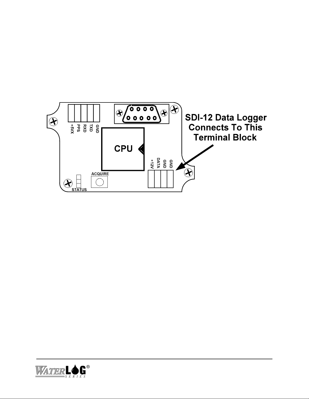
SDI-12 Connections
To connect the SDI-12 data logger, slide the cable through the Hubble connector until enough wires
are exposed to make the proper connections to the screw terminals. Tighten the Hubble connector
hand tight to make a secure seal around the cable. Connect the wires to the terminal block as
labeled. Make sure no bare wires are touching the PC board or any components on it.
H-339 Operation 1-3
Page 9

First Time Acquire
Once the H-339 is installed and powered, the user can press the ‘Acquire’ button on the main
interface board to start an acquire operation, see figure # 1. The first time acquire may take longer
than normal as the position (location on earth) will be unknown. After the H-339 has acquired a
valid time and position, it will remember this location allowing it to acquire faster in the future. The
‘Status’ light will blink while it is trying to gain a fix to the satellites. Once it has locked on to 3 or
more satellites with sufficient signal strength, valid data will be available and the light will stay on
steady. After pressing the Acquire button the H-339 will try to acquire for approximately four
minutes.
If the H-339 does not acquire after using the ‘Acquire’ button a few times, then use the ‘GPS Utility’
software to see how many satellites are in view and what signal strength is coming from them. With
the ‘GPS Utility’ software running and a cable between the PC and the 9 pin connector on the
interface board, press the ‘Acquire’ button to start the process. The H-339 will try to acquire as long
as this software is running and the cable is connected. It is now possible to reposition the GPS
module to see if a better view of the sky can be found. See appendix B for an overview of the GPS
Utility software.
1-4 Operation H-339
Page 10

Operation
The H-339 includes an integrated GPS module capable of tracking up to12 satellites at a time. The
SDI-12 section of the H-339 handles power management and all communication between the data
recorder and the GPS module. During normal operation, the data recorder sends an address together
with a command to the H-339 sensor. The H-339 wakes up from its low power sleep mode, turns
on and collects data from the GPS module and stores the data in its data buffer. Once the data is
ready, the data recorder collects the data from the H-339's data buffer.
Programming the H-339
The H-339 comes from the factory with its address set to ‘0'. This is the only option that can be
programmed on the H-339. Use the change address command explained in chapter 2 to change the
address. The address is stored in EEPROM within the H-339 and will not be lost if the power is
disconnected. If more than one sensor is to be connected to the SDI-12 bus, make certain each
sensor has a unique sensor address.
The H-339 will also ALWAYS respond to valid commands with an address of ‘g’. The H-339 was
mainly developed for use with the WATERLOG Series of data logger providing a means to keep the
time clocks as accurate as possible. The data logger will always use ‘g’ as the address for
communicating with the H-339.
®
Programming the Data Recorder
Even though the H-339 was mainly developed for use with the WATERLOG series of data logger,
it may be used with any data logger that has an SDI-12 interface. The following describes both
applications.
Generic Data Logger: You must prepare your data recorder to receive and record the H-339 data.
Since data recorders differ widely, refer to your recorder manufacturer's directions. In general,
program the data recorder to measure and record up to 9 values from the H-339 sensor via the
SDI-12 port. Your data recorder must issue an “aM!” command then collect the data with a “aD0"
and “aD1" commands, as explained in Chapter 2.
®
H-339 Operation 1-5
Page 11

WATERLOG Series Using H-339 for Time Sync: The WATERLOG Series of data loggers have
®®
a menu option that allow the user to enable or disable time sync from the H-339. When enabled the
WATERLOG data logger will try to sync to the GPS time once a day just after midnight, universal
®
standard time. Time updates will happen as listed in the following table.
CONFIGURATION TIME UPDATE PROCESS
Data Logger Only, No
GOES Radio
Data Logger and SE-100 or
SE-300 Radio
The data logger time clock is
updated.
The data logger and the GOES
radio time clock are both updated.
Data Logger and SE-1200 The SE-1200 has a built in GPS
system to keep its time accurate,
and the data logger can sync from
this system making the H-339
unneeded for this configuration.
Data logger and Telonics
GOES radio.
The data logger time is updated
but the Telonics radio will not
allow its time clock to be changed
once the radio is enabled.
Table # 2
Position Data
The position data is returned in a format of DDMM.mmmm for the latitude and DDDMM.mmmm
for the longitude. This format stands for Degrees, Minutes, Decimal Minutes. For example a value
of 3851.3334 is 38 degrees, 51 minutes, and 3334/10,000 minutes.
To convert this to degrees, minutes, seconds; take the .mmmm portion of the value and multiply by
60. For example, take the value 3851.3334, and multiply 0.3334 by 60 to obtain seconds;
0.3334 * 60 = 20.004 seconds
Now 3851.3334 DDMM.mmmm Equals 38 degrees 51 minutes and 20.004 seconds.
1-6 Operation H-339
Page 12

Time Accuracy
When the data logger requests data from the H-339, the H-339 responds to the data logger with a
message indicating it can take up to 240 seconds to get valid data. The H-339 can have valid data
in as little as 30 seconds. Soon after the data is valid, the H-339 sends a service request to the data
logger so the data logger can collect the data. The service request will come sometime between 30
seconds and 240 seconds. The service request is synchronized to a timing pulse from the GPS
module to provide very accurate timing possibilities. This timing pulse is called ‘Pulse Per Second’
or ‘PPS’ and is one of the wires from the GPS module. The time returned to the data logger is the
exact time (within nanoseconds) at the rising edge of this pulse. The service request is sent to the
data logger typically at 115 microseconds after the PPS pulse, (± 10 microseconds). Figure # 4
shows these pulses.
Figure 5
As long as the data logger can read the data from the sensor consistently time wise, a time offset can
be established to give accuracies to less than one second. The H-339 will never return a valid time
with the value for seconds equal to X8 (08, 18, 28 etc) or higher so the data logger can increment the
seconds data without having to be concerned with roll over. This makes generating a time offset
easier as long as the offset is 2 second or less.
Words of Caution
!Keep the lead wires as short as possible.
!Use shielded cables in noisy environments.
!Always clean and inspect the GPS module when at the site.
!Never count on the time or position accuracy if the valid flag is not set.
H-339 Operation 1-7
Page 13

SDI-12 Command and Response Protocol
SDI-12 Command and Response Protocol
Chapter 2
This is a brief description of the Serial Digital Interface (SDI-12) Command and Response protocol
used by the WATERLOG Series Model H-339 sensor. Included is a description of the commands
and data format supported by the H-339.
Refer to the document "A SERIAL DIGITAL INTERFACE STANDARD FOR HYDROLOGIC
AND ENVIRONMENTAL SENSORS". Version 1.2 April 12, 1996 Coordinated by the SDI-12
Support Group, 135 East Center, Logan, Utah.
During normal communication, the data logger sends an address together with a command to the H339 sensor. The H-339 then replies with a "response". In the following descriptions, SDI-12
commands and responses are enclosed in quotes. The SDI-12 address and the command/response
terminators are defined as follows:
"a" Is the sensor address. The following ASCII Characters are valid addresses: "0-9", "A-
Z", "a-z", "*", "?". Sensors will be initially programmed at the factory with the
address of "0" for use in single sensor systems. Addresses "1 to 9" and "A to Z" or
"a to z" can be used for additional sensors connected to the same SDI-12 bus.
Address "*" and "?" are "wild card" addresses which select any sensor, regardless of
its actual address. Unique to the H-339 is that it will always respond to address ‘g’.
"!" Is the last character of a command block.
®
"<cr><lf>" Are carriage return (0D) hex and line feed (0A) hex characters. They are the
last two characters of a response block.
Notes:
#All commands/responses are upper-case printable ASCII characters.
#Commands must be terminated with a "!" character.
#Responses are terminated with <cr><lf> characters.
#The command string must be transmitted in a contiguous block with no gaps of more than
1.66 milliseconds between characters.
H-339 SDI-12 Command and Response Protocol 2-1
Page 14

Measure Command
The Measure Command causes a measurement sequence to be performed. Data values generated
in response to this command are stored in the sensor's buffer for subsequent collection using "D"
commands. The data will be retained in the sensor until another "M", “C” or "V" command is
executed.
Command Response Description
-------------- ---------------------- ------------------------------------
"aM!" "atttn<cr><lf>" Initiate measurement
Where: a is the sensor address ("0-9", "A-Z", "a-z", "*", "?").
M is an upper-case ASCII character
ttt is a three digit integer (000-999) specifying the maximum time, in seconds, the
sensor will take to complete the command and have measurement data available in
its buffer.
n is a single digit integer (0-9) specifying the number of values that will be placed in
the data buffer. If "n" is zero (0), no data will be available using
subsequent "D" commands.
Upon completion of the measurement, a service request "a<cr><lf>" is sent to the data logger
indicating the data is ready. The data logger may wake the sensor with a break and collect the data
anytime after the service request is received or the specified processing time has elapsed.
Example of a H-339 "aM!" command:
Command Response Time Values Description
------------- --------------------- ------- -------- ------------------------------"aM!" "a2409<cr><lf>" 240 sec 9 Get Time / Position Data
Subsequent Command Response
--------------------------- ------------------------------------------------------------------
"aD0" a+ss+mm+hh+DD+MM+YY<cr><lf>
"aD1" a+DDMM.mmmm+DDDMM.mmmm+F<cr><lf>
Where:
ss = Seconds, mm = Minutes hh = Hours DD = Date MM = Month YY = Year
DDMM.mmmm = Latitude DDDMM.mmmm = Longitude F = Pass / Fail Flag
2-2 SDI-12 Command and Response Protocol H-339
Page 15

Concurrent Measurement Command
This is a new command for the Version 1.2 SDI-12 Specification. A concurrent measurement is one
which occurs while other SDI-12 sensors on the bus are also taking measurements. This command
is similar to the “aM!” command, however, the nn field has an extra digit and the sensor does not
issue a service request when it has completed the measurement. Communicating with other sensors
will NOT abort a concurrent measurement. Data values generated in response to this command are
stored in the sensor's buffer for subsequent collection using "D" commands. The data will be
retained in the sensor until another "M", “C” or "V" command is executed.
Command Response Description
------------- ---------------------- ------------------------------------
"aC!" "atttnn<cr><lf>" Initiate measurement
Where: a is the sensor address ("0-9", "A-Z", "a-z", "*", "?").
C is an upper-case ASCII character
ttt is a three digit integer (000-999) specifying the maximum time, in seconds, the
sensor will take to complete the command and have measurement data available in
its buffer.
nn is a two digit integer (00-99) specifying the number of values that will be placed in
the data buffer. If "n" is zero (0), no data will be available using
subsequent "D" commands.
The data logger may wake the sensor with a break and collect the data anytime after the specified
processing time has elapsed.
H-339 SDI-12 Command and Response Protocol 2-3
Page 16

Send Data Command
The Send Data command returns sensor data generated as the result of previous "aM!", “aC!” or
"aV!" commands. Values returned will be sent in 33 characters or less. The sensor's data buffer will
not be altered by this command.
Command Response
------------- --------------------------------------
"aD0!" through "aD9!" "apd.d ... pd.d<cr><lf>"
Where: a is the sensor address ("0-9", "A-Z", "a-z", "*", "?").
D0..D9 are upper-case ASCII characters.
p Is a polarity sign (+ or -)
d.d represents numeric digits before and/or after the decimal. A decimal may be
used in any position in the value after the polarity sign. If a decimal is not
used, it will be assumed to be after the last digit.
For example: +3.29 +23.5 -25.45 +300
If the number of values returned by a "aD0!" command is less than the number specified by the result
of the previous "M" or "V" command, the rest of the data must be collected using "aD1", "aD2!"
.... "aD9!" until all values specified have been collected. If one or more values were specified and
a "aD0!" returns no data (a<CR><LF> only), it means that the measurement was aborted and a new
"M" command must be sent. The following is an example of the "aD0!" and “aD1!” supported by
the H-339.
Example of a H-339 "aD0!" command:
Previous command Response
----------------------- ------------------------------------------
"aM!" "a0022<cr><lf>"
Subsequent Command Response
--------------------------- ------------------------------------
"aD0" a+ss+mm+hh+DD+MM+YY<cr><lf>
"aD1" a+DDMM.mmmm+DDDMM.mmmm+F<cr><lf>
Where:
ss = Seconds, mm = Minutes hh = Hours DD = Date MM = Month YY = Year
DDMM.mmmm = Latitude DDDMM.mmmm = Longitude F = Pass / Fail Flag
2-4 SDI-12 Command and Response Protocol H-339
Page 17

Initiate Verify Command
The Verify Command causes a verify sequence to be performed. The result of this command is
similar to the "aM!" command except that the values generated are fixed test data and the results of
a diagnostic checksum test. The data generated in response to this command is placed in the sensor's
buffer for subsequent collection using "D" commands. The data will be retained in the sensor until
another “M”, “C” or “V” command is executed.
Command Response Description
------------- ------------------------- ---------------------------
"aV!" "atttn<cr><lf>" Initiate verify sequence
Where: a is the sensor address ("0-9", "A-Z", "a-z", "*", "?").
V is an upper-case ASCII character.
ttt is a three digit integer (000-999) specifying the maximum time, in seconds, the
sensor will take to complete the command and have data available in its buffer.
n is a single digit integer (0-9) specifying the number of values that will be placed in
the data buffer. If "n" is zero (0), no data will be available using
subsequent "D" commands.
Example of a H-339 "aV!" command:
Command Response Time Values Description
------------- --------------------- ------- -------- ---------------------------
"aV!" "a0013<cr><lf>" 1 sec 3 Return fixed data and diagnostic
data for testing purposes.
Subsequent Command Response
--------------------------- --------------------------------------------
"aD0" a+123.456+78.9+y<cr><lf>
Key Description Units
------------- ------------------------- --------------------------- +123.456 Fixed test data
+78.9 Fixed test data
y ROM checksum test 0 = Failed, 1 = Passed
H-339 SDI-12 Command and Response Protocol 2-5
Page 18

Send Identification Command
The Send Identification command responds with sensor vendor, model, and version data. Any
measurement data in the sensor's buffer is not disturbed.
Command Response
------------- ------------------------------------------------------------
"aI!" "allccccccccmmmmmmvvvxx...xx<cr><lf>"
Where: a is the sensor address ("0-9", "A-Z", "a-z", "*", "?").
I is an upper-case ASCII character.
ll is the SDI-12 version compatibility level, e.g. version 1.2 is represented as "12".
cccccccc is an 8 character vendor identification to be specified by the vendor and usually in the
form of a company name or its abbreviation.
mmmmmm is a 6 character field specifying the sensor model number.
vvv is a 3 character field specifying the sensor version number.
xx...xx is an optional field of up to a maximum of 13 characters to be used for serial number
or other specific sensor information not relevant to operation of the data logger.
Example of a H-339 "aI!" command:
"a12 DAA H-339vvvS#nnnnnnVkkk<cr><lf>"
H-339 implementation of the optional 13 character field:
S#nnnnnnVkkk (12 bytes total)
Where:
"nnnnnn" is a six character sensor serial number
"kkk" is a three digit sensor firmware revision level
2-6 SDI-12 Command and Response Protocol H-339
Page 19

Send Acknowledge Command
The Send Acknowledge Command returns a simple status response which includes the address of
the sensor. Any measurement data in the sensor's buffer is not disturbed.
Command Response
------------- -------------------------
"a!" "a<cr><lf>"
Where: a Is the sensor address ("0-9", "A-Z", "a-z", "*", "?").
Change Sensor Address
The Change Sensor Address Command allows the sensor address to be changed. The address is
stored in non-volatile EEPROM within the sensor. The H-339 will not respond if the command was
invalid, the address was out of range, or the EEPROM programming operation failed.
Command Response Description
------------- ------------------------- ---------------------------
"aAn!" "n<cr><lf>" Change sensor address
Where: a is the current (old) sensor address ("0-9", "A-Z", "a-z", "*", "?"). An ASCII "*"
may be used as a "wild card" address if the current address is unknown and only one
sensor is connected to the bus.
A is an upper-case ASCII character.
n is the new sensor address to be programmed ("0-9", "A-Z", "a-z", "*", "?").
NOTE: To verify the new address use the "Identify Command."
H-339 SDI-12 Command and Response Protocol 2-7
Page 20

Power Supply
Voltage: 9.6 to 16.0 Volts DC
Current:
Sleep Mode: 250 microamps
Active: 150 mA maximum
Measurement Time
SDI-12: 240 seconds max
SDI-12 Output
Baud Rate: 1200
Protocol: SDI-12, 7-bit even parity,
1 stop bit
Output Voltage Levels:
minimum high level: 3.5 volts
maximum low level: 0.8 volts
maximum cable length: 500 ft.
Appendix A
Specifications
Environmental
Operating Temperature: -40E to 50EC
Storage Temperature: -50E to 70EC
Humidity: Condensing Tolerant
Connectors
SDI-12 Output: Hubble weather tight connector with internal screw terminal block
GPS Module: Hubble weather tight connector with internal screw terminal block
Warranty
The WATERLOG H-339 is warranted against defects in materials and workmanship for one year
from date of shipment.
®
H-339 Specifications A-1
Page 21

Appendix B
GPS Utility Software
Overview
The GPS Utility program allows a user to easily monitor the status of a GPS unit. The program
connects to a GPS unit through COM1 and communicates at 4800 baud.
Functionality
The Signal Strength is a
signal to noise ratio for
each satellite. These bars
Position of the GPS unit. Both
latitude and longitude are in
degrees, minutes and decimal
The number of satellites which are
currently in view out of 12. The number
of satellites which are being used to
extrapolate data. If 3 or more satellites
are being used, the Status may be
VALID, otherwise it is INVALID.
Select a Communication
port to use with the H-339.
The Time and Date are
synchronized to the
international standard
GPS time.
H-339 GPS Utility Software B-1
 Loading...