

Page 1

Model
H-335
SDI-12 Inclinometer
Owner's Manual
Version 1.3
Design Analysis Associates
75 West 100 South
Logan, UT 84321 USA
Phone: (435) 753-2212
Fax: (435) 753-7669
Internet: www.waterlog.com
E-mail: sales@waterlog.com
Page 2

Page 3

User Agreement/
W
ATER
1. NATURE OF THE PRODUCT
This agreement accompanies an interface module comprising firmware, circuitry and other electronic
equipment in an enclosed housing, and packaged together with written instructional materials. The
packaged electronic circuitry and instructional materials herein are collectively referred to as the
“PRODUCT.” The PRODUCT is made available from DESIGN ANALYSIS ASSOCIATES, INC., of
75 West 100 South, Logan, Utah 84321 (hereinafter referred to as “DESIGN ANALYSIS”), and contains
information and embodies technology that is confidential and proprietary to DESIGN ANALYSIS, and the
availability and use of the PRODUCT is extended to you, the USER, solely on the basis of the terms of
agreement which follow.
2. ACKNOWLEDGMENTS BY USER
Opening the package which encloses the accompanying PRODUCT indicates your acceptance of the terms
and conditions of this agreement and constitutes an acknowledgment by you of the confidential and
proprietary nature of the rights of DESIGN ANALYSIS in the PRODUCT.
3. DUTIES OF YOU, THE USER
In consideration for the access to and use of the PRODUCT extended to you by DESIGN ANALYSIS and
to protect the confidential and proprietary information of DESIGN ANALYSIS, USER agrees as follows:
LOG® Warranty
(a) USER agrees that they will not remove from the exterior of the housing of the PRODUCT any safety
warnings or notices of proprietary interest placed thereon by DESIGN ANALYSIS.
(b) USER agrees that they shall not disassemble or otherwise reverse engineer the PRODUCT.
(c) USER agrees to treat the PRODUCT with the same degree of care as USER exercises in relation to
their own confidential and proprietary information.
4. TERM
USER may enjoy these rights only as long as their possession of the PRODUCT shall continue to be
rightful. These rights will cease if the PRODUCT is returned to DESIGN ANALYSIS under the terms of
any redemption offer, warranty, or money-back guarantee, or if USER transfers the PRODUCT to another
party on terms inconsistent with this agreement.
5. LIMITED WARRANTY
(b) What is Covered
DESIGN ANALYSIS warrants that for a period of twelve months from the time of purchase the
functions to be performed by the PRODUCT will be substantially in compliance with USER
documentation. DESIGN ANALYSIS also warrants that the PRODUCT will be free from defects
in materials and workmanship for a period of ONE YEAR from the date of purchase.
(b) What USER Must Do
If the product fails to satisfy the above warranty, USER must notify DESIGN ANALYSIS in
writing within the applicable period specified above and reasonably cooperate with the directions
they received from DESIGN ANALYSIS.
H-355
User Agreement/W
ATER
LOG® Warranty W-1
Page 4

(c) What DESIGN ANALYSIS Will Do
DESIGN ANALYSIS will repair the PRODUCT or will endeavor to provide a replacement of
same within a reasonable period of time. In the event that DESIGN ANALYSIS is unable to make
the necessary repairs or replacement within a reasonable period of time, the original purchase price
will be refunded upon the return of the PRODUCT to DESIGN ANALYSIS.
(d) Limitations
(i) THE ENTIRE REMEDY FOR BREACH OF THIS LIMITED WARRANTY SHALL
BE LIMITED TO REPLACEMENT OF THE DEFECTIVE PRODUCT OR
REFUNDING OF THE PURCHASE PRICE, AS SET FORTH ABOVE. IN NO
EVENT WILL THE LIABILITY OF DESIGN ANALYSIS TO USER OR TO ANY
OTHER PARTY EXCEED THE ORIGINAL PURCHASE PRICE OF THE PRODUCT,
REGARDLESS OF THE FORM OF THE CLAIM.
(ii) EXCEPT FOR THE EXPRESS WARRANTIES ABOVE, DESIGN ANALYSIS
SPECIFICALLY DISCLAIMS ALL OTHER WARRANTIES, INCLUDING,
WITHOUT LIMITATION, ALL IMPLIED WARRANTIES OF MERCHANTABILITY
AND FITNESS FOR A PARTICULAR PURPOSE.
(iii) UNDER NO CIRCUMSTANCES WILL DESIGN ANALYSIS BE LIABLE FOR
SPECIAL, INCIDENTAL, CONSEQUENTIAL, INDIRECT, OR ANY OTHER
DAMAGES OR CLAIMS ARISING FROM THE USE OF THIS PRODUCT, THIS
INCLUDES LOSS OF PROFITS OR ANY OTHER COMMERCIAL DAMAGES,
EVEN IF ADVISED OF THE POSSIBILITY OF SUCH DAMAGES. IN NO EVENT
WILL DESIGN ANALYSIS BE LIABLE FOR ANY CLAIMS, LIABILITY, OR
DAMAGES ARISING FROM MODIFICATION MADE THEREIN, OTHER THAN
BY DESIGN ANALYSIS.
(iv) THIS LIMITED WARRANTY GIVES USER SPECIFIC LEGAL RIGHTS. USER
MAY ALSO HAVE OTHER RIGHTS WHICH VARY FROM STATE TO STATE.
SOME STATES DO NOT ALLOW LIMITATIONS ON HOW LONG AN IMPLIED
WARRANTY LASTS OR THE EXCLUSION OF INCIDENTAL OR
CONSEQUENTIAL DAMAGES, SO THOSE LIMITATIONS OR EXCLUSIONS
MAY NOT APPLY.
6. GOVERNING LAW
This Agreement and its validity and interpretation shall be governed by the laws of the State of Utah,
notwithstanding any choice of law rules of Utah or any other state or jurisdiction.
W-2 User Agreement/W
ATER
LOG® Warranty
H-355
Page 5

Chapter 1
H-335 Operation
1.1 Operation
The W
ATER
LOG® H-335 is a precision, single axis, wide range inclinometer which measures the angle
(position) of radial water control gates. The H-335 is easy to use, works with any data recorder/logger with
a SDI-12 interface and can be interfaced with SCADA systems. The “Serial-Digital Interface” is ideal for
data logging applications with the following requirements:
Multiple sensors on a 3-wire bus
Low system cost
Up to 200 feet of cable between a sensor and the data recorder
The H-335 has the following features:
Easily attaches to I-beam of gate structure
Gravity referenced sensor allows installation anywhere on the gate structure
Scales the gate position into user units of feet, inches, meters, etc.
Built-in intelligence automatically calculates both gate height and arc length
No hysteresis or backlash
0.03 accuracy over full position and temperature range
Sealed water-tight enclosure
No moving parts or bearings
H-335
Chouteau Lock and Dam, OklahomaCopan Lake, Oklahoma
H-335 Operation 1-1
Page 6

1.2 Theory of Operation
The H-335 has a single axis tilt sensor, signal processing circuitry, 14-bit analog to digital converter and a
microprocessor. The sensor is a ceramic based electrolytic tilt sensor which provides high resolution and
very good linearity. The sensor is constructed as a hermetically sealed ceramic cavity with electrodes
partially submerged in a conductive fluid. The ratio between submersed areas of the facing electrodes is
proportional to the inclination angle. The electronics provide an AC sensor excitation together with a
precision, ratiometric peak-hold detector. Because scale factor of electrolytic sensors is sensitive to
temperature, the H-335 has a built-in digital temperature sensor. The microprocessor uses a math
polynomial to correct for temperature induced effects and any non-linear characteristics of sensor.
1.3 Problems with Winch Mechanism and Existing Measurement Systems
Tainter gates are typically controlled with a motor operated winch mechanism. The gear box for the winch
has a “sundial” scale and pointer which shows the current gate opening. Often the mechanism also has a
selsyn transmitter which allows the gate position to be monitored in a nearby control room. The sundial and
selslyn driven scales are usually marked in units of “feet”. Unfortunately most winch mechanisms have no
provisions for monitoring the gate position with a data logger or SCADA (System Control and Data
Acquisition) system. In the past, users have tried using incremental shaft encoders connected to the winch
with a sprocket and chain. This technique has the following shortcomings:
The radius of the winch drum changes as the cable winds up, giving a non-linear readout.
The lift cables stretch as the gate is raised off the sill.
The backlash (hysteresis) in the drive chain between the winch drum and encoder can be large.
Each installation requires custom mechanisms, enclosures and setup.
The winch shaft is not accessible on some gearboxes.
The H-335 overcomes many of the problems associated with measuring the position of a tainter gate by
directly monitoring the angle of the gate structure. Backlash and non-linear effects of the winch drum and
cables are completely bypassed.
1-2 Introduction
H-335
Page 7

1.4 Gate Geometry
Most users are interested in measuring the gate opening or “height”. Upon closer examination, however, the
geometry of a tainter gate is somewhat complex. The following definitions and illustration shows the
geometry of a typical tainter gate.
1.4.1 Terms and Definitions
Trunnion Bearing: The pivot point of the gate structure.
Sill Elevation: The elevation relative to a datum of the point where the gate seals against the
bottom of the spillway.
Gate Radius: The distance between the center of the trunnion bearing and the outside of the gate
skin plate.
Gate Angle: The angle, in degrees, through which the gate has opened (0 = closed).
Gate Arc Length: The distance the gate face moves through the partial curve of a circle.
Gate Height: The vertical distance between the bottom of the gate and a horizontal line passing
through the sill.
Sill Angle: The angle, in degrees, between a horizontal line through the trunnion bearing and
the point at which the gate rests on the spillway.
The tilt sensor in the H-335 measures the angle of the gate structure referenced to gravity. The H-335 can
be installed anywhere on the gate structure since the entire structure rotates the same relative to gravity.
The sensor does not need to be on the center of the gate’s rotating axis.
The H-335 measures and reports the UserAngle relative to the closed position (0 = closed). For
convenience, the H-335 also internally calculates and reports GateHeight and GateArcLength. Normally,
users program their data recorder to record only one of the three parameters. Each of these three
measurement parameters has advantages and disadvantages:
H-335
H-335 Operation 1-3
Page 8
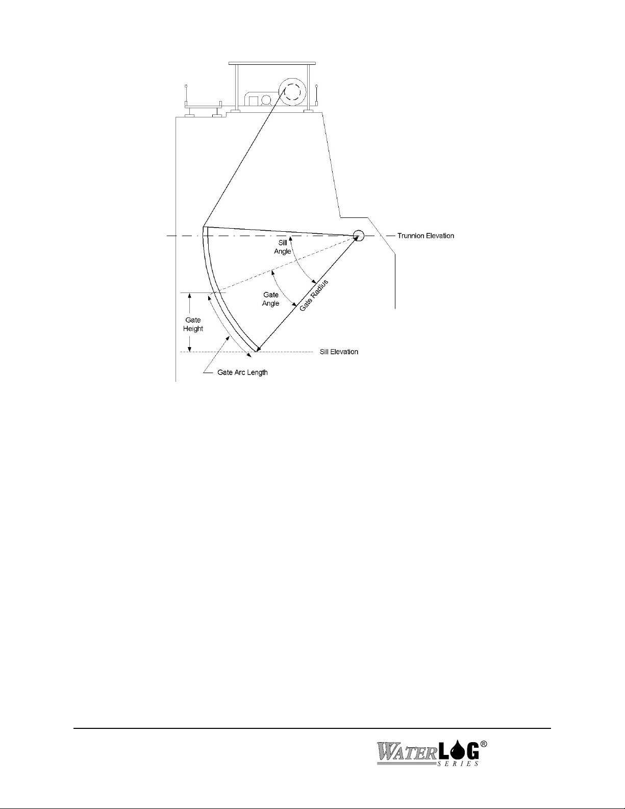
Figure 1 Gate Geometry
×
1.4.2 User Angle
The UserAngle is the angle, in degrees, thru which the gate has moved relative to the closed position. All
other calculations are based on this measurement. Some dams have a spillway which slopes rapidly
downward from the point where the gate contacts the sill. For these structures, the water flow calculation is
a complex geometric problem because the actual weir opening (distance between the gate and the spillway)
changes as the vertical point from the bottom of the gate first moves upward, then down the incline of the
spillway. For complex gate geometries, program your data logger to record the UserAngle and do the
necessary calculations during post-processing of the data. The UserAngle parameter is calculated internally
in the H-335 using the following equation:
UserAngle = (SensorAngle UserSlope) - UserOffset
The UserSlope is a constant set to either +1.0 or -1.0 and must be programmed into the H-335 at
installation (see Section 1.8). The UserOffset value is automatically calculated when the extended “aXZO”
command is issued after the installation is completed.
1-4 Introduction
H-335
Page 9

()(
)
[
]
1.4.3 Arc Length
The ArcLength is distance the gate face moves through the partial curve of a circle. Normally this value is
not recorded by the data logger. The H-335 calculates and reports this value for field test and verification
purposes and is calculated internally in the H-335 using the following equation:
UserAngle GateRadius
× ×
π
GateArcLength =
180
If water is flowing through the gate, the GateHeight cannot be directly measured with a measuring tape
because the water flow sweeps the tape away. However, if the tape is attached to the face of the gate, and is
tangent to the gate, the Arc Length can be directly measured in the field.
1.4.4 Gate Height
The GateHeight is the vertical distance between the bottom of the gate and a horizontal line passing thru
the sill. Normally this value is recorded and used in a weir calculation to determine water flow. The
GateHeight parameter is calculated internally in the H-335 using the following equation:
GateHeight = GateRadius sin SillAngle sin SillAngle-UserAngle
The GateRadius and SillAngle are constants and must be programmed into the H-335 during installation.
1.5 Programming the Data Recorder
You must prepare your data recorder to receive and record the H-335 data. Since data recorders differ
widely, refer to your recorder manufacturer's directions. In general, program the data recorder to input four
values via the SDI-12 port. Usually only one or two of the parameters is actually recorded. Your data
recorder must issue an “aM!” command, then collect the data with a “aD0 ” command, as explained in
Chapter 2. The H-335 places four data values in its data buffer:
−
Where:
a+AA.AA+BB.BB+CC.CC+DD.DD<CR><LF>
+AA.AA = GateArcLength (inches, meters etc.)
+BB.BB = GateHeight (inches, meters etc.)
+CC.CC = UserAngle (Degrees of angle)
+DD.DD = SensorTemperature (C)
H-335
H-335 Operation 1-5
Page 10
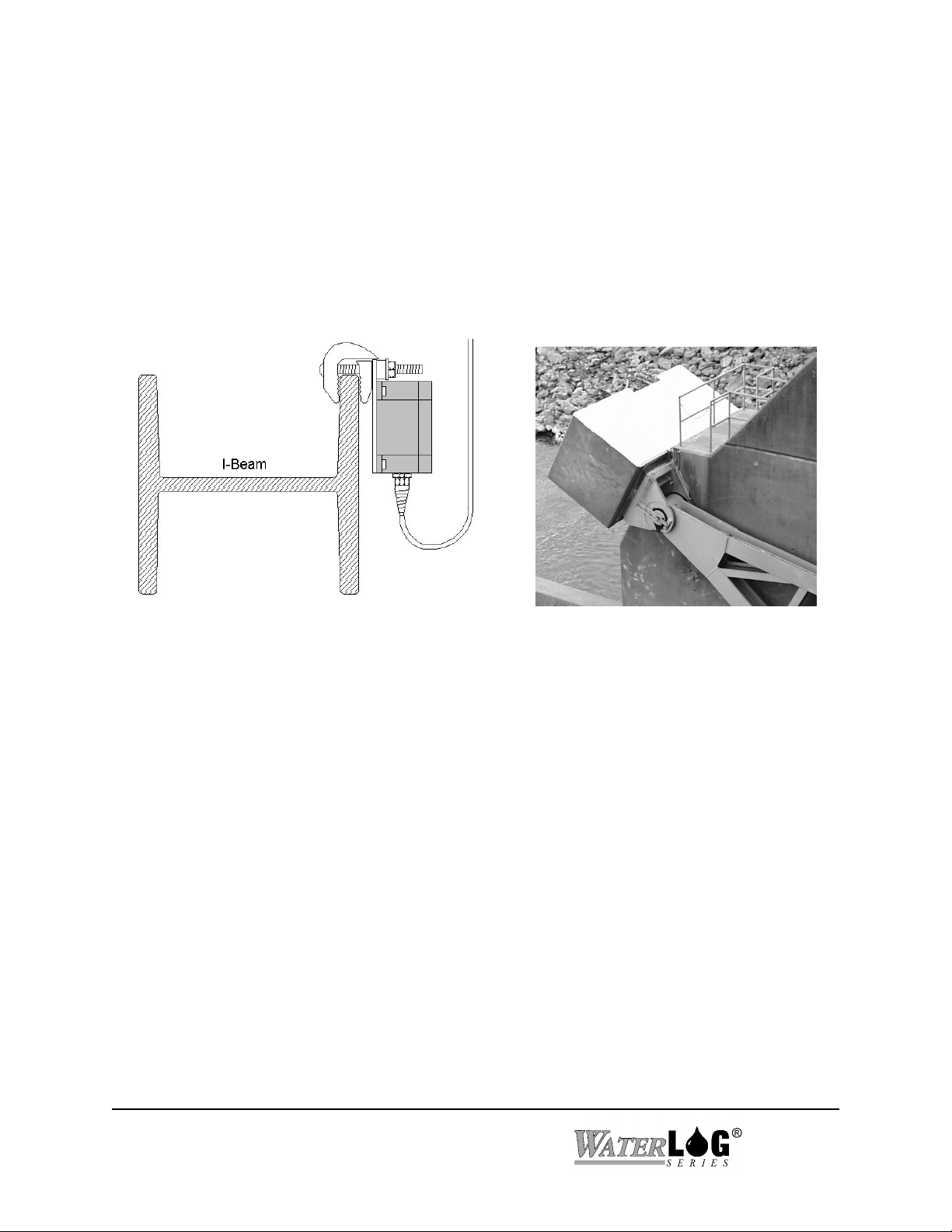
1.6 Installation
Since the H-335 is a gravity referenced tilt sensor, it can be installed anywhere on the gate structure. The
H-335 must be installed exactly vertical and in the plane the tainter gate rotates. If the H-335 is not vertical
the senor will suffer an off-axis trigonemetric error as the gate is raised. The mount clamp has a 2-axis
gimbal which allows the inclinometer to be adjusted to compensate for camber in the gate structure.
The best place to install the sensor is near the trunnion bearing between the I-beam of the gate arm and the
concrete pier. Either the left or right arm will work. This location is protected from direct sunlight, logs and
debris, and allows for a short cable. The beam clamps allow easy installation with no drilling and will work
for beams up to 2.0 inches thick. Make certain the cable has sufficient slack for the entire rotation of the
gate.
The UserAngleSlope coefficient in the H-335 must be programmed appropriately depending on whether the
H-335 is installed on the left or right arms of a gate and whether on the inside or outside of the I-beam (see
Figure 2).
1.7 Making Connections to the H-335
Since the H-335 is normally exposed to the sun and weather, a cable rated for water immersion and
sunlight resistance is required. A black urethane or similar sunlight/waterproof rated cable is recommended.
Make certain the power is OFF before making any connections. To access the wiring terminal block, open
the cover of the H-335 by removing the four cover screws. Whenever tightening or loosening the cover
screws, turn each screw only a turn or two at a time. Try to equalize the stress on the lid. This is especially
important when the O-ring in the lid is near full compression.
Make certain the cable properly seals in the grommet of the liquid-tight cable fitting and that the O-ring in
the fitting is tight against the box. The connection must be water tight. Other grommet diameters and
fittings are available from the factory.
The H-335 has a removable 4-pin wiring terminal block for connecting the SDI-12 cable. Unplug the
terminal block and make the connections to the cable. The connections are labeled on the circuit board.
Check to make certain the connections are correct, then plug the terminal block into the H-335 circuit
1-6 Introduction
H-335
Page 11

board. This eliminates stressing the connector and circuit board while tightening the terminal block screws.
Make certain the wires do not touch any of the internal components, especially if your cable has a bare
drain wire.
1.8 Programming the H-335
The H-335 has several fixed constants which must be programmed before installation. We recommend
doing this in the lab, before installing the H-335 on the tainter gate.
Step 1: Program the sensor with the proper SDI-12 address, make certain each sensor has a unique
sensor address. See Chapter 2 for details of the “aAn” change address command.
The H-335 comes from the factory with the following settings:
Sensor Address: 0
UserAngleSlope: +1.0
UserAngleOffset: 0.0
GateRadius: 36.0
SillAngle: 51.057
With these values the GateHeight and GateArcLength parameters will be in units of feet for a gate with a
radius of 36.0 feet. The setup is stored in EEPROM within the H-335 and will not be lost if the power is
disconnected. The extended commands for changing these settings is described in detail in Chapter 2.
Use the extended SDI-12 commands “aXWCn” and “AaXRCn” to write and read respectively the
following settings:
Step 2 (coefficient 1): Set the UserAngleSlope as needed for your installation. Set the slope to +1.0
for a gate which opens clockwise while facing the H-335 cover. Set the slope to
-1.0 for a gate which opens counter-clockwise while facing the sensor cover
(see Figure 2).
Step2 (coefficient 2): Make certain the UserAngleOffset value is set to 0.0.
Step3 (coefficient 3): Set the GateRadius as needed for your tainter gate. This is the distance between
the center of the trunnion bearing and the outside face of the skin plate. This value also determines the units
for the GateArcLength and GateHeight data output values. If this value is in units of feet, the data output
will be in units of feet etc.
Step4 (coefficient 4): Set the SillAngle as needed for your tainter gate. Use a calculator and the
following formula to compute the proper value:
TrunnionElevation-SillElevation
For Example:
SillAngle = ArcSin
ArcSin
391'-363'
GateRadius
36'
=
51057.
H-335
H-335 Operation 1-7
Page 12

1.9 Installing the H-335 and setting the mechanical sensor offset
The tilt sensor in the H-335 has a physical ±40 calibrated range. This allows sufficient dynamic range to
measure a gate which opens up to 80. To work properly, the sensor must be mechanically adjusted during
installation to preserve the available physical dynamic range. This is done by loosening two screws and
rotating the internal sensor assembly. The mechanical offset adjustments are made while monitoring the
SensorAngle parameter. This is the raw sensor reading with no adjustment for slope or offset. The
UserAngle parameter is processed with a slope and offset term to produce the more useful 0.0 to +80.0
reading for the data recorder.
With the gate closed the mechanical offset must be set near (but not beyond) one end of the sensor’s
measurement range. The proper setting depends on which gate arm the H-335 is installed and which side of
the I-beam the H-335 is mounted (see Figure 2). For example; with a gate which can open up to 70 and
which the inclinometer rotates clockwise (while facing the H-335 cover) as the gate opens, the sensor
should be rotated until SensorAngle reads ~ -35. When this gate is fully open the raw SensorAngle will
read +35. With the same gate but with the inclinometer installed such that it rotates counter-clockwise
(while facing the H-335 cover) as the gate opens, the sensor must be mechanically adjusted to +35. When
this gate is fully open the raw SensorAngle will read -35.
The H-335 fiberglass enclosure can be installed in any
position in the plane of rotation. If possible, locate the
connector on the bottom to prevent water from standing
on the connector. The internal ceramic sensor element
is symmetrical and will still make measurements if
installed upside down. However, if the sensor is upside
down, the calibration will be invalid, the slope will be
wrong and the output data confusing. Check to make
certain the wires exit the red plastic cover at the 2:00
o’clock position when the gate is in the center of its
travel arc.
1-8 Introduction
H-335
Page 13

Figure 2 Installation Configurations
In practice the following steps must be done with two people. One working on the gate pier and the other on
the dam catwalk with a data logger or laptop computer connected to the SDI-12 bus. A hand held radio
makes it easier to communicate be between the two workers. During the installation procedure the
SensorAngle must be monitored in real time. Ignore the UserAngle value at this time. The offset adjustment
can be done in two ways:
H-335
H-335 Operation 1-9
Page 14

1.9.1 Method I
Issue repeated SDI-12 “aM1” and “aD0” commands.
For the “aM1” command, the H-335 places 6 parameters in its data buffer where:
a = Sensor Address (0-9,A-Z)
+AA.AA = UserAngle (degrees of angle)
+BB.BBB = SensorAngle (degrees of angle)
+CCCC = Raw A/D Positive Count (±8192)
+DDDD = Raw A/D Negative Count (±8192)
+EEEE = Raw A/D Positive Count (±16384)
+FF.FF = SensorTemperature (C)
1.9.2 Method II
Use the “aXTEST” command (see Chapter 2).
This command is primarily used for production testing and requires the use of a H-419 Sidekick interface
and a PC. This command causes the H-335 to transmit unsolicited real-time data for testing purposes. This
is not compliant with the SDI-12 specification and is not used with data loggers.
XTEST continually prints the following parameters in a single line:
Sensor Address (0-9, A-Z)
SensorAngle (Angle)
For example:
1 +1.200
1 +1.200
1 +1.500
1 +1.700
1 +1.900
etc.
Step 5: Remove the cover from the H-335 and make the wiring connections. Leave the cover off, do
not bolt the assembly to the I-beam at this time.
Step 6: Connect the +12V power. Issue an “aI” identifiy command to make certain the sensor is
connected and working.
Step 7: Make certain the tainter gate is fully closed and resting on the sill.
1-10 Introduction
H-335
Page 15

Step 8: Slightly loosen the two #4-40 allen socket head screws which retain the ceramic sensor
assembly. Some dams have the tainter gate I-beam located above the platform on the concrete
pier. If you can access the sensor after installation, follow steps 9a-11a. If you cannot access
the sensor when it is bolted to the I-beam, follow steps 9b-11b.
For Installations where the sensor is accessible
Step 9a: Tightly bolt the H-335 to the I-beam with the beam clamps.
Step 10a: Use the data logger or laptop computer to monitor the SensorAngle. Carefully rotate the
internal sensor assembly for the desired value. Make certain the internal ceramic sensor is not
upside down. Sensors mounted such that the inclinometer rotates clockwise as the gate opens
must be set to -34to -38. Sensors mounted such that the inclinometer rotates counterclockwise as the gate opens must be set to +34to +38. The adjustment is quite sensitive and
requires a bit of patience. When the desired setting is reached, tighten the two allen screws.
Step 11a: Re-install the cover and proceed to Step 12. Whenever tightening or loosening the cover
screws, turn each screw only a turn or two at a time. Try to equalize the stress on the lid. This
is especially important when the O-ring in the lid is near full compression.
For Installations where the sensor is NOT accessible
Step 9b: Temporarily rest the H-335 flush against the top of the I-Beam while holding it exactly
vertical.
Step 10b: Use the data logger or laptop computer to monitor the SensorAngle. Carefully rotate the
internal sensor assembly for the desired value. Make certain the internal ceramic sensor is not
upside down. Sensors mounted such that the inclinometer rotates clockwise as the gate opens
must be set to -34to -38. Sensors mounted such that the inclinometer rotates counterclockwise as the gate opens must be set to +34to +38. The adjustment is quite sensitive and
requires a bit of patience. When the desired setting is reached, tighten the two allen screws.
The angle setting can be approximate because it is more accurately fine tuned in the next step.
Step 11b: Re-install the cover. Whenever tightening or loosening the cover screws, turn each screw only
a turn or two at a time. Try to equalize the stress on the lid. This is especially important when
the O-ring in the lid is near full compression. Loosely bolt the H-335 to the I-beam with the
beam clamps. While monitoring the SensorAngle fine tune the angle by tapping or prying the
aluminum mounting plate with a screw driver. When the desired angle is obtained, tighten the
beam clamp bolts.
H-335
H-335 Operation 1-11
Page 16

Test the Installation
Step 12: Check to make certain the sensor is still at the desired SensorAngle. Make certain the gate is
fully closed and resting on the sill. Wait at least 15 minutes or so for the sensor temperature
to stabilize before proceeding to the next step.
Step 13: Issue the extended “aXZO” Zero Offset command. The H-335 will make a fresh angle
measurement and use this value to automatically update the UserAngleOffset value to
produce a UserAngle reading = 0.0 .
Step 14: Make a “aM” measurement. The GateArcLength, GateHeight and UserAngle parameters
should all be zero. Raise the gate and check for proper (increasing) readings.
The SDI-12 “aM” command makes the following measurements:
a +AA.AA+BB.BB+CC.CC+DD.DD<CR><LF>
Where:
a = Sensor Address (0-9, A-Z)
+AA.AA = GateArcLength (inches, meters etc.)
+BB.BB = GateHeight (inches, meters etc.)
+CC.CC = UserAngle (degrees of angle)
+DD.DD = SensorTemperature (C)
This completes installation and testing of the H-335.
1-12 Introduction
H-335
Page 17

Chapter 2
SDI-12 Command and Response Protocol
2.1 SDI-12 Command and Response Protocol
This is a brief description of the Serial Digital Interface (SDI-12) Command and Response protocol used by
the W
ATER
LOG® Series Model H-335 sensor. Included is a description of the commands and data format
supported by the H-335.
Refer to the document "A SERIAL DIGITAL INTERFACE STANDARD FOR HYDROLOGIC AND
ENVIRONMENTAL SENSORS". Version 1.2 April 12, 1996 Coordinated by the SDI-12 Support Group,
135 East Center, Logan, Utah.
During normal communication, the data recorder sends an address together with a command to the H-335 SDI-
12 sensor. The H-335 then replies with a "response". In the following descriptions, SDI-12 commands and
responses are enclosed in quotes. The SDI-12 address and the command/response terminators are defined as
follows:
"a" Is the sensor address. The following ASCII Characters are valid addresses: "0-9", "A-
Z", "a-z", "*", "?". Sensors will be initially programmed at the factory with the
address of "0" for use in single sensor systems. Addresses "1 to 9" and "A to Z" or
"a to z" can be used for additional sensors connected to the same SDI-12 bus.
Address "*" and "?" are "wild card" addresses which select any sensor, regardless of
its actual address.
Notes:
"!" Is the last character of a command block.
"<cr><lf>" Are carriage return (0D) hex and line feed (0A) hex characters. They are the last two
characters of a response block.
All commands/responses are upper-case printable ASCII characters.
Commands must be terminated with a "!" character.
Responses are terminated with <cr><lf> characters.
The command string must be transmitted in a contiguous block with no gaps of more than 1.66
milliseconds between characters.
H-335
SDI-12 Command and Response Protocol 2-1
Page 18

2.2 Measure Command
The Measure Command causes a measurement sequence to be performed. The H-335 supports three different
measure commands (“aM”, “aM1" and “aM2"). Data values generated in response to this command are stored
in the sensor's buffer for subsequent collection using "D" commands. The data will be retained in the sensor
until another "M", “C” or "V" command is executed.
Command Response Description
------------------ ---------------------- ------------------------------------
"aM!" "atttn<cr><lf>" Initiate measurement
Where:
a is the sensor address ("0-9", "A-Z", "a-z", "*", "?").
M is an upper-case ASCII character
ttt is a three digit integer (000-999) specifying the maximum time, in seconds,
the sensor will take to complete the command and have measurement data
available in its buffer.
n is a single digit integer (0-9) specifying the number of values that
will be placed in the data buffer. If "n" is zero (0), no data will be
available using subsequent "D" commands.
Upon completion of the measurement, a service request "a<cr><lf>" is sent to the data recorder indicating the
sensor data is ready. The data recorder may wake the sensor with a break and collect the data anytime after
the service request is received or the specified processing time has elapsed.
Example of a H-335 "aM!" command:
Command Response Time Values Description
"aM!" "a0034<cr><lf>"
3 sec 4 Make current measurement
Subsequent Command Response
"aD0" a+AA.AA+BB.BB+CC.CC+DD.DD<cr><lf>
Where:
AA.AA = Gate Arc Length
BB.BB = Gate Height
CC.CC = User Angle (Degrees)
DD.DD = Sensor Temperature (C)
2-2 SDI-12 Command and Response Protocol
H-335
Page 19

“aM1" Command
Example of a H-335 "aM1!" command:
Command Response Time Values Description
"aM1!" "a0036<cr><lf>"
3 sec 6 Make measurement
Subsequent Command Response
"aD0" a+AA.AA+BB.BBB+CCCC+DDDD+EEEE+FF.FF<cr><lf>
Where:
+AA.AA = User Angle
+BB.BBB = Sensor Angle
+CCCC = Raw A/D Positive Count (±8192)
+DDDD = Raw A/D Negative Count (±8192)
+EEEE = Raw A/D Count (±16384)
+FF.FF = Sensor Temperature (C)
“aM2" Command
Example of a H-335 "aM2!" command:
Command Response Time Values Description
"aM2!" "a0031<cr><lf>"
3 sec 1 Make measurement
Subsequent Command Response
"aD0" a+AA.AA<cr><lf>
Where:
+AA.AA = Gate Height
H-335
SDI-12 Command and Response Protocol 2-3
Page 20

2.3 Concurrent Measure Command
This is a new command for the Version 1.2 SDI-12 Specification. A concurrent measurement is one which
occurs while other SDI-12 sensors on the bus are also taking measurements. This command is similar to the
“aM!” command, however, the nn field has an extra digit and the sensor does not issue a service request when
it has completed the measurement. Communicating with other sensors will NOT abort a concurrent
measurement. Data values generated in response to this command are stored in the sensor's buffer for
subsequent collection using "D" commands. The data will be retained in the sensor until another "M", “C” or
"V" command is executed.
Command Response Description
"aC!" "atttnn<cr><lf>" Initiate measurement
Where:
a is the sensor address ("0-9", "A-Z", "a-z", "*", "?").
C is an upper-case ASCII character
ttt is a three digit integer (000-999) specifying the maximum time, in seconds,
the sensor will take to complete the command and have measurement data
available in its buffer.
nn is a two digit integer (00-99) specifying the number of values that will
be placed in the data buffer. If "n" is zero (0), no data will be available
using subsequent "D" commands.
The data recorder may wake the sensor with a break and collect the data anytime after the specified processing
time has elapsed.
2-4 SDI-12 Command and Response Protocol
H-335
Page 21

2.4 Send Data Command
The Send Data command returns sensor data generated as the result of previous "aM!", aM1!", aM2!", “aC!”
or "aV!" commands. Values returned will be sent in 33 characters or less. The sensor's data buffer will not
be altered by this command.
Command Response
"aD0!" through "aD9!" "apd.d ... pd.d<cr><lf>"
Where:
a is the sensor address ("0-9", "A-Z", "a-z", "*", "?").
D0..D9 are upper-case ASCII characters.
p Is a polarity sign (+ or -)
d.d represents numeric digits before and/or after the decimal. A decimal may be used in
any position in the value after the polarity sign. If a decimal is not used, it will be
assumed to be after the last digit.
For example: +3.29 +23.5 -25.45 +300
If one or more values were specified and a "aD0!" returns no data (a<CR><LF> only), it means that the
measurement was aborted and a new "M" command must be sent.
Example of a H-335 "aD0!" command:
Previous command Response
"aM!" "a0034<cr><lf>"
Subsequent Command Response
"aD0" a+AA.AA+BB.BB+CC.CC+DD.DD<cr><lf>
Where:
AA.AA = Gate Arc Length
BB.BB = Gate Height
CC.CC = User Angle (Degrees)
DD.DD = Sensor Temperature (C)
H-335
SDI-12 Command and Response Protocol 2-5
Page 22

2.5 Continuous Measurements
This is a new command for the Version 1.2 SDI-12 Specification. Sensors that are able to continuously monitor
the phenomena to be measured, such as a cable position, do not require a start measurement command. They
can be read directly with the R commands (R0!...R9!). The R commands work exactly like the D (D0!...D9!)
commands. The only difference is that the R commands do not need to be preceded with an M command. The
H-335 DOES NOT supports the aR0! continuous measurement commands.
2.6 Initiate Verify Command
The Verify Command causes a verify sequence to be performed. The result of this command is similar to the
"aM!" command except that the values generated are fixed test data and the results of diagnostic checksum
tests. The data generated in response to this command is placed in the sensor's buffer for subsequent collection
using "D" commands. The data will be retained in the sensor until another “M”, “C” or “V” command is
executed.
Command Response Description
"aV!" "atttn<cr><lf>" Initiate verify sequence
Where:
a is the sensor address ("0-9", "A-Z", "a-z", "*", "?").
V is an upper-case ASCII character.
ttt is a three digit integer (000-999) specifying the maximum time, in seconds, the
sensor will take to complete the command and have data available in its buffer.
n is a single digit integer (0-9) specifying the number of values that will be placed
in the data buffer. If "n" is zero (0), no data will be available using
subsequent "D" commands.
Example of a H-335 "aV!" command:
Command Response Time Values Description
"aV!" "a0013<cr><lf>"
1 sec 3 Return fixed data and diagnostic
data for testing purposes.
Subsequent Command Response
"aD0" a+123.456+78.9+y<cr><lf>
Key Description Units
+123.456 Fixed test data
+78.9 Fixed test data
y ROM checksum test 0 = Failed, 1 = Passed
2-6 SDI-12 Command and Response Protocol
H-335
Page 23

2.7 Send Acknowledge Command
The Send Acknowledge Command returns a simple status response which includes the address of the sensor.
Any measurement data in the sensor's buffer is not disturbed.
Command Response
"a!" "a<cr><lf>"
Where:
a Is the sensor address ("0-9", "A-Z", "a-z", "*", "?").
H-335
SDI-12 Command and Response Protocol 2-7
Page 24

2.8 Send Identification Command
The Send Identification command responds with sensor vendor, model, and version data. Any measurement
data in the sensor's buffer is not disturbed.
Command Response
"aI!" "allccccccccmmmmmmvvvxx...xx<cr><lf>"
Where:
a is the sensor address ("0-9", "A-Z", "a-z", "*", "?").
I is an upper-case ASCII character.
ll is the SDI-12 version compatibility level, e.g. version 1.2 is represented as "12".
cccccccc is an 8 character vendor identification to be specified by the vendor and usually in the
form of a company name or its abbreviation.
mmmmmm is a 6 character field specifying the sensor model number.
vvv is a 3 character field specifying the sensor version number.
xx...xx is an optional field of up to a maximum of 13 characters to be used for serial number
or other specific sensor information not relevant to operation of the data recorder.
Example of a H-335 "aI!" command:
"a12 DAA H-335vvvS#nnnnnnVkkk<cr><lf>"
H-335 implementation of the optional 13 character field:
S#nnnnnnVkkk
(12 bytes total)
Where:
"nnnnnn" is a six character sensor serial number
"kkk" is a three digit sensor firmware revision level
2-8 SDI-12 Command and Response Protocol
H-335
Page 25

2.9 Change Sensor Address
The Change Sensor Address Command allows the sensor address to be changed. The address is stored in
non-volatile EEPROM within the sensor. The H-335 will not respond if the command was invalid, the address
was out of range, or the EEPROM programming operation failed.
Command Response Description
"aAn!" "n<cr><lf>" Change sensor address
Where:
a is the current (old) sensor address ("0-9", "A-Z", "a-z", "*", "?"). An ASCII "*"
may be used as a "wild card" address if the current address is unknown and only one
sensor is connected to the bus.
A is an upper-case ASCII character.
n is the new sensor address to be programmed ("0-9", "A-Z", "a-z", "*", "?").
NOTE: To verify the new address use the "Identify Command."
Example of a "Change Sensor Address" command:
Command Response Description
"aA2!" "2<cr><lf>"
Change sensor address to "2"
H-335
SDI-12 Command and Response Protocol 2-9
Page 26

2.10 Extended “Read Coefficient” Command
The H-335 processes the sensor measurement data with a set of coefficients. Each coefficient is
programmable, allowing the H-335 to be used on gates with different geometries, and to scale the
height and distance output values to user desired engineering units. This command allows the user
to read any of the coefficients. At the factory the coefficients are set to the following values.
Coefficient Default Value Description
C1 +1.0 User angle slope (compensates for clockwise or counter-
clockwise mounting )
C2 0.0 User angle offset (provides zero output with gate against sill)
C3 36.0 (Feet) Gate Radius (determines user units; inches, feet etc.)
C4 51.05756 Degrees Sill Angle (angle of the gate sill with respect to trunnion
bearing)
Command Response Description
"aXRCn!" "a0011<cr><lf>"
Where:
a is the sensor address ("0-9", "A-Z", "a-z", "*", "?").
XRC are upper case characters
Read Coefficient
n is coefficient number 1 to 4.
This command takes 001 seconds to complete and places 1 value in the data buffer. Use the “aD0"
command to collect and view the data.
Example of a H-335 Extended "Read Coefficient" command:
Command Response Time Values Description
"aXRC3!" "a0011<cr><lf>"
Subsequent Command Response
"aD0" a+36.000<cr><lf>
1 sec 1 Read Coefficient 3
(gate radius)
2-10 SDI-12 Command and Response Protocol
H-335
Page 27

2.11 Extended “Write Coefficient” Command
The H-335 processes the sensor measurement data with a set of coefficients. Each coefficient is
programmable, allowing the H-335 to be used on gates with different geometries, and to scale the
height and distance output values to user desired engineering units. This command allows the user
to write (change) any of the coefficient values. The new value is stored in non-volatile EEPROM
within the sensor. Once the new value is written to the EEPROM, a copy is sent to the sensor data
buffer for verification. This data can be viewed by using a subsequent "D" command. To verify any
coefficient any other time, use the "Read Coefficient" command.
Command Response Description
"aXWCnddd!" "a0011<cr><lf>"
Where:
a is the sensor address ("0-9", "A-Z", "a-z", "*", "?").
XWC are upper case characters.
n is the coefficient number to program, 1 to 4
ddd is the new coefficient value. The input format is
very flexible. Some examples are shown below.
Write Coefficient n
20.0
0.195
-500
5.93E-4
This command takes 001 seconds to complete and places 1 value in the data buffer. Use the “aD0"
command to collect and view the data.
Example of a H335 extended "Write Coefficient" command:
Command Response Tim e Values Description
"aXWC1-1!" "a0011<cr><lf>"
opens.
Subsequent Command Response
"aD0" a-1<cr><lf>
1 sec 1 Set Coefficient 1 to -1 indicating
the inclinometer rotates
counter-clockwise as the gate
H-335
SDI-12 Command and Response Protocol 2-11
Page 28

2.12 Extended “XTEST” and “XRAW” Commands
These commands are used for installation or production testing and requires the use of a H-419
Sidekick interface and a PC. These commands causes the H-335 to transmit unsolicited real-time
data for testing purposes. This is not compliant with the SDI-12 specification and is not used with
data loggers.
To activate the test mode, first send the command “aXTEST!” or “aXRAW” from the PC. The H335 will automatically display a new line of data about once per second. This test mode may be used
to help troubleshoot the installation by providing a continuous readout of sensor data. The test mode
is exited by sending any new command on the SDI-12 bus (a BREAK terminates the test). It may
take a few tries to exit if the command is sent at the same time data is being sent from the H-335.
Removing power from the H-335 also causes it to exit this mode.
“aXTEST” displays the following data:
a (sensor address)
SensorAngle (degrees)
Example of the XTEST test display:
a +1.200
a +1.500
a +1.700
a +1.900
etc.
“aXRAW” displays the following data:
a (sensor address)
Gate Arc Length (feet, meters etc.)
Gate Height (feet, meters etc.)
User Angle (degrees)
Sensor Angle (degrees)
Raw Positive A/D count (±8192)
Raw Negative A/D count (±8192)
Raw Positive - Negative A/D count (±16384)
Sensor Temperature. (C)
Example of the “XRAW” test display:
a +1.200 +.1.103 +4.565 -32.231 -2639 +5836 +8475 +23.52
a +1.500 +.1.213 +5.183 -31.613 -2234 +5835 +8069 +23.51
a +1.700 +.1.451 +5.397 -31.399 -2656 +5848 +8504 +23.54
a +1.900 +.1.602 +5.565 -31.231 -2678 +5786 +8464 +24.03
2-12 SDI-12 Command and Response Protocol
H-335
Page 29

2.13 Extended “XZO” Command
This command is used to automatically zero the gate angle offset. The “aXZO” command
causes the H-335 to make a fresh angle measurement and use this value to automatically update the
UserAngleOffset value to produce a UserAngle reading = 0.00
Make certain the gate is fully closed and resting on the sill. Wait at least 15 minutes or so after
applying +12V power for the sensor temperature to stabilize before issuing the “aXZO” command.
This command should be used only during installation or maintenance.
Example of a H-335 Extended "Zero Offset" command:
Command Response Time Values Description
"aXZO!" "a0031<cr><lf>"
Subsequent Command Response
"aD0" a+12.000<cr><lf>
3 sec 1 Zero the UserAngle
The new UserAngleOffset
H-335
SDI-12 Command and Response Protocol 2-13
Page 30

Page 31

General
Sensor: ceramic, single axis, linear, wide angle
Type: electrolytic fluid
Range: -40 to +40 (80 total)
Resolution: 0.005
Accuracy: +-0.03 (absolute over full range)
(0.25 inch gate height with 36' gate radius)
(0.13 inch gate height with 20' gate radius)
Offset Adjust: software command with gate against sill
Temperature: -30 to +50 C (calibrated range)
Settling Time: <300ms
SDI-12 Measurement Time: 2 Sec
SDI-12 Output
Baud Rate: 1200
Protocol: SDI-12, 7-bit even parity, 1 stop bit
Output Voltage Levels:
minimum high level: 3.5 volts
maximum low level: 0.8 volts
maximum cable length: 250 ft.
SDI-12 Output Data Parameters:
1 - Gate Arc Length (feet, inches, meters, etc.)
2 - Gate Height (feet, inches, meters etc.)
3 - Gate Angle (degrees)
4 - Temperature (C )
Appendix A
Specifications
Power Requirements
Voltage Input: 10.0 to 16.0 Volts DC
Current
Measuring: 30 mA
Standby 20 mA typical
Environmental
Operating Temperature: -30 to +60 C
Storage Temperature: -50 to +70 C
Mechanical
Material: 40% graphite filled fiberglass
Size: 4.76" x 4.76" x 2.5" high
Rating: NEMA 4X, 6
Connector: liquid tight strain relief fitting
.08" to .24" dia cable
Beam Clamp: 2-Inch max I-beam thickness.
Mount fixture is adjustable in
3-axis to compensate for camber
in the gate structure.
Cable: not included
Recommended Cable:
polyurethane or similar, rated for
water immersion and sunlight
resistance.
Warranty
The W
ATER
LOG® H-335 is warranted against defects
in materials and workmanship for one year from date
of shipment.
H-335
Appendix A Specifications A-1
Page 32

H-335
Appendix A Specifications A-2
 Loading...