

Page 1
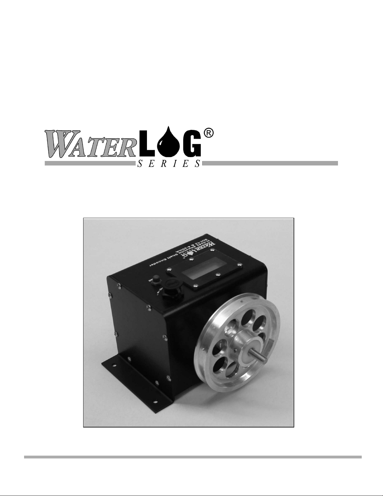
Model
H-3342
Absolute Shaft Encoder with
LCD Display, SDI-12 and 4-20mA Outputs
Owner's Manual
Version 1.3
75 West 100 South, Logan, Utah 84321 Phone: (435) 753-2212 Fax: (435) 753-7669 Web: http://www.waterlog.com E-mail: waterlog@waterlog.com
D E S I G N A N A L Y S I S A S S O C I A T E S , I N C .
Page 2

75 West 100 South, Logan, Utah 84321 Phone: (435) 753-2212 Fax: (435) 753-7669 Web: http://www.waterlog.com E-mail: waterlog@waterlog.com
D E S I G N A N A L Y S I S A S S O C I A T E S , I N C .
Page 3

User Agreement/
WATERLOG Warranty
1. NATURE OF THE PRODUCT
This agreement accompanies a water level measuring system comprising firmware, circuitry and other
electronic equipment in an enclosed housing, and packaged together with written instructional materials.
The packaged electronic circuitry and instructional materials herein are collectively referred to as the
“PRODUCT.” The PRODUCT is made available from DESIGN ANALYSIS ASSOCIATES, INC., of
75 West 100 South, Logan, Utah 84321 (hereinafter referred to as “DESIGN ANALYSIS”), and contains
information and embodies technology that is confidential and proprietary to DESIGN ANALYSIS, and
the availability and use of the PRODUCT is extended to you, the USER, solely on the basis of the terms
of agreement which follow.
2. ACKNOWLEDGMENTS BY USER
Opening the package which encloses the accompanying PRODUCT indicates your acceptance of the
terms and conditions of this agreement and constitutes an acknowledgment by you of the confidential and
proprietary nature of the rights of DESIGN ANALYSIS in the PRODUCT.
3. DUTIES OF YOU, THE USER
In consideration for the access to and use of the PRODUCT extended to you by DESIGN ANALYSIS
and to protect the confidential and proprietary information of DESIGN ANALYSIS, USER agrees as
follows:
®
(a) USER agrees that they will not remove from the exterior of the housing of the
PRODUCT any safety warnings or notices of proprietary interest placed thereon by
DESIGN ANALYSIS.
(b) USER agrees that they shall not disassemble or otherwise reverse engineer the
PRODUCT.
(c) USER agrees to treat the PRODUCT with the same degree of care as USER exercises in
relation to their own confidential and proprietary information.
4. TERM
USER may enjoy these rights only as long as their possession of the PRODUCT shall continue to be
rightful. These rights will cease if the PRODUCT is returned to DESIGN ANALYSIS under the terms of
any redemption offer, warranty, or money-back guarantee, or if USER transfers the PRODUCT to
another party on terms inconsistent with this agreement.
5. LIMITED WARRANTY
(a) What is Covered
DESIGN ANALYSIS warrants that for a period of twelve months from the time of delivery the
functions to be performed by the PRODUCT will be substantially in compliance with USER
documentation. DESIGN ANALYSIS also warrants that the PRODUCT will be free from
defects in materials and workmanship for a period of ONE YEAR from the date of delivery.
(b) What USER Must Do
H-3342 User Agreement/WATERLOG Warranty W-1
®
Page 4

If the product fails to satisfy the above warranty, USER must notify DESIGN ANALYSIS in
writing within the applicable period specified above and reasonably cooperate with the directions
they received from DESIGN ANALYSIS.
(c) What DESIGN ANALYSIS Will Do
DESIGN ANALYSIS will repair the PRODUCT or will endeavor to provide a replacement of
same within a reasonable period of time. In the event that DESIGN ANALYSIS is unable to
make the necessary repairs or replacement within a reasonable period of time, the original
purchase price will be refunded upon the return of the PRODUCT to DESIGN ANALYSIS.
(d) Limitations
(i) THE ENTIRE REMEDY FOR BREACH OF THIS LIMITED WARRANTY
SHALL BE LIMITED TO REPLACEMENT OF THE DEFECTIVE PRODUCT
OR REFUNDING OF THE PURCHASE PRICE, AS SET FORTH ABOVE.
IN NO EVENT WILL THE LIABILITY OF DESIGN ANALYSIS TO USER
OR TO ANY OTHER PARTY EXCEED THE ORIGINAL PURCHASE PRICE
OF THE PRODUCT, REGARDLESS OF THE FORM OF THE CLAIM.
(ii) EXCEPT FOR THE EXPRESS WARRANTIES ABOVE, DESIGN ANALYSIS
SPECIFICALLY DISCLAIMS ALL OTHER WARRANTIES, INCLUDING,
WITHOUT LIMITATION, ALL IMPLIED WARRANTIES OF
MERCHANTABILITY AND FITNESS FOR A PARTICULAR PURPOSE.
(iii) UNDER NO CIRCUMSTANCES WILL DESIGN ANALYSIS BE LIABLE
FOR SPECIAL, INCIDENTAL, CONSEQUENTIAL, INDIRECT, OR ANY
OTHER DAMAGES OR CLAIMS ARISING FROM THE USE OF THIS
PRODUCT, THIS INCLUDES LOSS OF PROFITS OR ANY OTHER
COMMERCIAL DAMAGES, EVEN IF ADVISED OF THE POSSIBILITY OF
SUCH DAMAGES. IN NO EVENT WILL DESIGN ANALYSIS BE LIABLE
FOR ANY CLAIMS, LIABILITY, OR DAMAGES ARISING FROM
MODIFICATION MADE THEREIN, OTHER THAN BY DESIGN
ANALYSIS.
(iv) THIS LIMITED WARRANTY GIVES USER SPECIFIC LEGAL RIGHTS.
USER MAY ALSO HAVE OTHER RIGHTS WHICH VARY FROM STATE
TO STATE. SOME STATES DO NOT ALLOW LIMITATIONS ON HOW
LONG AN IMPLIED WARRANTY LASTS OR THE EXCLUSION OF
INCIDENTAL OR CONSEQUENTIAL DAMAGES, SO THOSE
LIMITATIONS OR EXCLUSIONS MAY NOT APPLY.
6. GOVERNING LAW
This Agreement and its validity and interpretation shall be governed by the laws of the State of Utah,
notwithstanding any choice of law rules of Utah or any other state or jurisdiction.
W-2 User Agreement/WATERLOG Warranty H-3342
®
Page 5

1.0 Introduction
Chapter 1
Introduction
The WATERLOG H-3342 is a digital shaft encoder which measures water depth by monitoring
the position of a float and pulley system. The H-3342 is easy to use and works with any SDI-12
data recorder. The “Serial-Digital Interface” is ideal for data logging applications with the
following requirements:
! Battery powered operation with minimal current drain
! Multiple sensors on a simple three-wire cable
! Up to 250 feet of cable between a sensor and the data recorder
(Use of H-423, SDI-12 to RS485 converter extends the range to 1000's of feet,
a H-4500 fiberoptic media converter works up to 1.2 miles)
The H-3342 has the following features:
! Non-contact optical encoder
! Absolute, shaft position is not lost if the power fails or is disconnected
! High resolution (65,536 counts/rev)
! ±32,768 max turns
! Zero backlash
! Scales the encoder position into user units of feet, meters, etc.
! Precision ball bearing design with special low temperature lubricant
! Threaded shaft compatible with existing pulleys
! Sealed enclosure protects from moisture and dirt
! Low current operation (less than 150 microamps typical standby)
! Water resistant connector provides easy hookup
! Continuous display readout always shows last measured value.
! ‘Read’ button causes the H-3342 to continuously update the display while the button is
pressed
! Front panel adjustment for manually setting the stage
! Front panel control for setting the SDI-12 address
! Optically isolated 4-20mA output
®
H-3342 Introduction 1-1
Page 6

1.1 Operation
The H-3342 is a precision shaft encoder with a resolution of 65,536 counts per revolution
(.000015 feet with 1.0 ft circumference pulley). Internally the H-3342 has two non-contact
encoders mounted on the same shaft. An optical encoder measures the shaft angle and a
magnetic turns counter counts the number of revolutions. The optical rotary position sensor
measures the shaft angle within a 360° range. As opposed to incremental encoders, the optical
encoder measures the absolute position rather than the change in position. Internally, an infrared
LED flashes through a circular bar code onto a linear array sensor. A microcontroller decodes
the image into a unique position. Due to manufacturing tolerances of the bar code, the accuracy is
less than the resolution; 4096 counts per revolution (.00024 feet with 1.0 ft circumference
pulley). The turn counter monitors complete revolutions of the shaft and can count up to
±32,768 revolutions. Together the encoders provide an “absolute” measurement. The shaft
position will not be lost if the power is removed, even if the shaft rotates while the power is off.
During normal operation, the SDI-12 data recorder sends an address together with a command to
the H-3342. The H-3342 wakes up from its low power sleep mode, converts the shaft position
into feet, meters or other units and stores this data in its data buffer. Once the data is ready, the
data recorder collects the data from the H-3342's data buffer.
1.2 LCD Display
The H-3342 has a 4-1/2 digit LCD display which shows the last measured value. The display
uses negligible power and is always visible. The display will show either ±199.99 or ±19999
digits depending on how the H-3342 is configured.
1.3 “Read” Button
When pressed, the ‘Read’ button causes the H-3342 to continuously make measurements and
update the display. The “±” sign flashes while making measurements indicating the display is
being updated even if the value is not changing. When the button is released the display will
hold the last measured value. Measurements initiated from an attached SDI-12 data logger will
also cause the display to update.
1.4 Using the Adjust Knob to Change the Stage
The offset adjustment is a rotary digital encoder which is accessed by removing the attached dust
cover. The encoder has a slot and is easily rotated with a screwdriver or other flat blade tool.
Replace the dust cap whenever the adjustment is not being used.
While the ‘Read’ button is pressed, the Adjust screw may be turned to increase or decrease the
current Stage reading. Turn the adjustment screw clock-wise to increase the Stage and counter-
clock wise to decrease the Stage. Turning the adjust screw slowly will change the hundredths
digit while turning the screw fast changes the tenths digit. This allows one control to make both
fine and course adjustments.
1-2 Introduction H-3342
Page 7

1.5 Using the Adjust Knob to Change SDI-12 Address
If the ‘Read’ button is held down while the H-3342 is being powered up, the display will show
the H-3342's current SDI-12 address. The SDI-12 address may be changed using the Adjust
screw. Turning the Adjust screw will change the address in the range of 0 to 9. When the Read
button is released, the new SDI-12 address is saved and the display switches to the normal stage
readout. To change the SDI-12 address again, the power must be disconnected and the special
power-up sequence repeated. The H-3342's address may also be changed with an extended SDI12 command (See Chapter 3).
1.6 4-20mA Output
The H-3342 has a 12-bit digital-to-analog converter (DAC), precision voltage reference and a 420mA current transmitter. The SDI-12 and 4-20mA sections are isolated from each other with a
high voltage digital opto-coupler. The Stage is scaled into a 12-bit value and loaded into the
digital-to-analog converter to control the current transmitter.
The 4-20mA output is updated whenever a measurement is made. If no measurements are made,
the 4-20mA output becomes “stale”. For industrial applications where the H-3342 is connected to
a SCADA or PLC system and low-power is not of concern, the H-3342 can be programmed to
make continuous measurements. See Chapter 3 for details. The H-3342 comes from the factory
with the power mode set to the Sleep mode.
Note: When the H-3342 is first powered up, the output current is set to 4.0mA. It remains at
4.0mA until the first measurement sequence. The digital-to-analog converter is powered from
the loop side of the opto-isolator. If the loop power is disconnected or is applied after the SDI-12
side is powered up, the data in the digital-to-analog converter will be lost. When the loop power
is restored, the 4-20mA output will be at an unknown value. Once a fresh SDI-12 measurement
is made, the digital-to-analog converter will be loaded with new valid data.
H-3342 Introduction 1-3
Page 8

1-4 Introduction H-3342
Page 9
Chapter 2
H-3342 Installation
2.0 Installation
The H-3342 is suitable for outdoor environments but must be installed in a protective enclosure
or gauge house. Normally, the H-3342 is screwed or bolted to a shelf in the gauge station with
the pulley and tape protruding over the edge of the shelf above the water. Make certain the
housing is level and the pulley and tape do not rub on any obstructions.
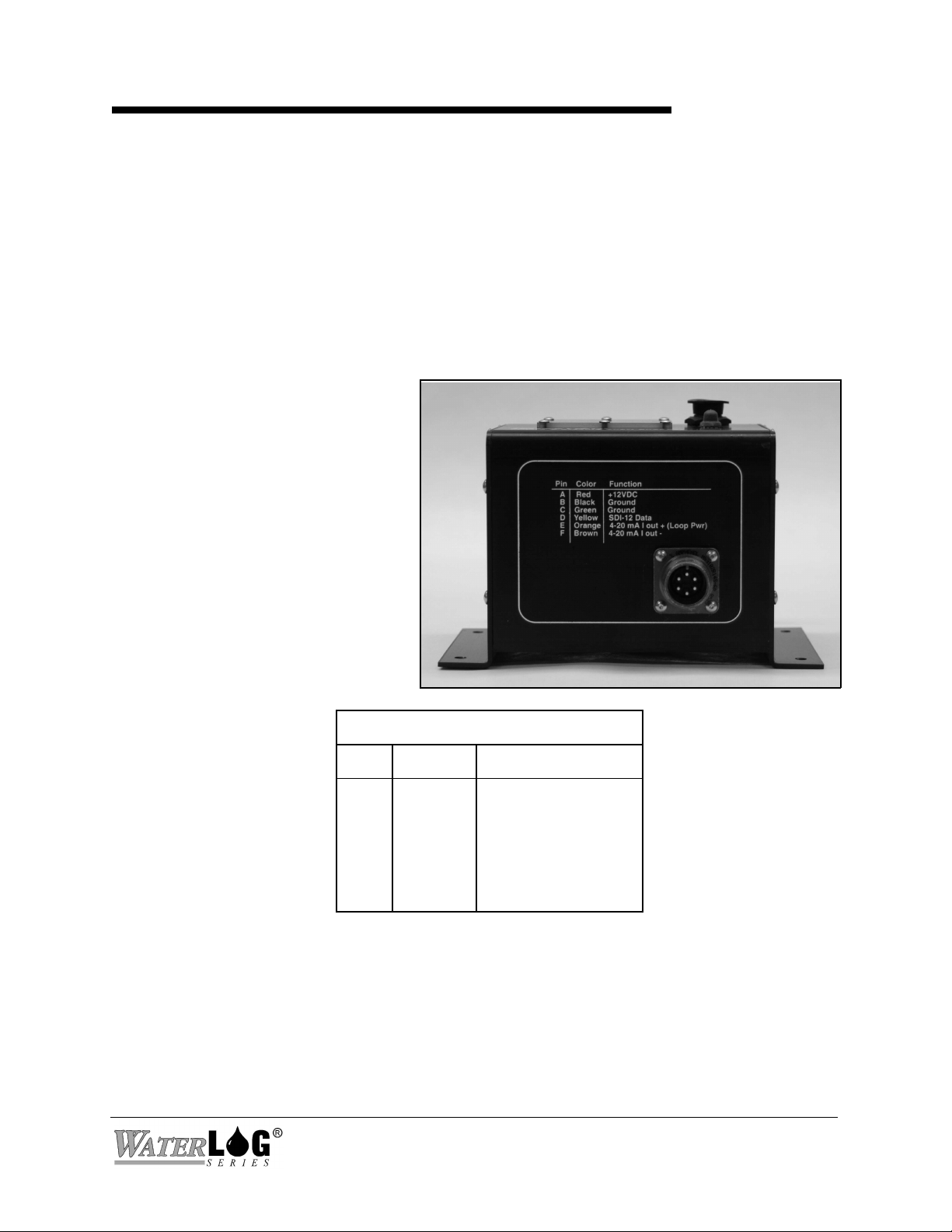
2.1 Making Output Connections to the H-3342
The H-3342 is a SDI-12 V1.2 compliant sensor. It connects directly to any data recorder with
SDI-12 capability. In addition, the H-3342 has an optically isolated, 4-20mA output.
The power for the H-3342 is supplied
by the +12Volt DC input. The table
below shows the proper connections.
The wiring diagram is printed on the
H-3342's housing. A 6-conductor
cable is supplied with the H-3342.
Cable Connections
Pin Wire Name
A
B
C
D
E
F
Red
Black
Green
Yellow
Orange
Brown
+12Volt DC
Ground
Ground
SDI-12 Data
4-20mA +
4-20mA -
H-3342 Installation 2-1
Page 10

2.2 4-20mA Output
Current loop sensors output a current rather than a voltage. The 4-20mA output will drive
standard industrial telemetry and process control instrumentation. Since the signal to noise
margin of 4-20mA is not large, take care to protect the wiring from noise and interference. The
loop power supply must be sufficient to maintain 8.5 to 35 Volts across the H-3342's output
terminals, in addition to whatever voltage is needed to maintain 20mA across the loop receiver
and interconnect wiring. The +12.0V SDI-12 power source will work if the resistance of your
loop receiver and wiring is less than 150 ohms.
8.5V + (150ohms * 20mA) = 11.5V
The 4-20mA output is reverse diode protected.
! Make certain there is 8.5 to 35V across the 4-20mA output terminals.
! Make certain the H-3342 is receiving +12V power from the SDI-12 bus.
! Use shielded 4-20mA cables in noisy environments.
2.3 Programming Your Data Recorder
You must prepare your data recorder to receive and record the H-3342 data. Since data recorders
differ widely, refer to your recorder manufacturer's directions. In general, program the data
recorder to input three values via the SDI-12 port. Usually only one or two of the parameters is
actually recorded. Your data recorder must issue an “aM!” command, then collect the data with a
“aD0" command, as explained in Chapter 3. The H-3342 places three parameters in its data
buffer:
Where:
a+BB.BBB+CC.CCC+D
a = Is the SDI-12 address 0-9, A-Z
BB.BBB = Stage in user units of Feet, Meters etc.
CC.CCC = Raw encoder position in units of revolutions (turns)
D = Encoder status:
0 = no error
1 = not enough light
2 = too much light
3 = misalignment or dust
4 = misalignment or dust
5 = misalignment or dust
6 = hardware problem
7 = fast mode error
8 = multi turn position not initialized
15 = no response from the encoder (data is unusable)
16 = turn counter error (data is unusable)
2-2 Installation H-3342
Page 11

2.4 Programming the H-3342
The H-3342 comes from the factory with the following settings:
SDI Address: 0 Power_Mode: 0 (Sleep)
StageSlope: 1.00 4-20mA_Hi: 20.0 Ft
StageOffset : 0.000 4-20mA_Lo: 4.0 Ft
LCD_Digits: 2 (±199.99) SDI_Digits: 3 (±xxx.xxx)
With these values the data will be in units of feet when used with a pulley having a
circumference of 12 inches. The slope can be changed to accommodate other pulley
circumferences or to change the data to other engineering units such as inches or Meters.
The LCD display can display the Stage in one of two formats: ±199.99 or ±19999. By default
SDI-12 measurement data is sent with more precision than will fit on the LCD display. The
default is three digits (x.xxx). Some users prefer to have the SDI-12 measurement data exactly
match the value on the LCD display. If this is the case, use the aXWSDInn command and set
SDI-Digits to 2, such that two digits beyond the decimal point are sent in the SDI-12 response
(x.xx).
The setups are stored in EEPROM within the H-3342 and will not be lost if the power is
disconnected. The extended commands for changing these setups are described in detail in
Chapter 3.
2.5 Programming the SDI-12 Address
If more than one sensor is to be connected to the SDI-12 bus, make certain each sensor has a
different sensor address. The H-3342 comes from the factory with its address set to “0". The
address can be programmed with either an SDI-12 command (see Chapter 3) or using the offset
adjust control on the H-3342's faceplate. To change the address with the adjust control, press and
hold the ‘Read’ button while the H-3342 is being powered up, the display will show the H-3342's
current SDI-12 address. The SDI-12 address may be changed in the range of 0 to 9 using the
adjust screw. When the Read button is released the new SDI-12 address is saved and the display
switches to the normal stage readout. To change the SDI-12 address again, the power must be
disconnected and the special power-up sequence repeated.
2.6 Setting the Stage
Many applications use the shaft encoder to monitor water in a stilling well. A float and pulley
translate the water level to rotation of the encoder’s shaft. Because the H-3342 is an absolute
encoder, the turn count and shaft angle cannot be “reset”. When the H-3342 is first installed, you
will want to adjust the StageOffset such that the LCD display and SDI-12 data correspond to the
current water elevation or stage as determined with a staff gauge or other datum.
With the shaft pointing toward you, rotating the encoder shaft clockwise produces an increasing
(positive) shaft position value. If this is backwards from your needs, either program the
StageSlope with a negative value, or exchange the float and counter weight on the pulley. To
adjust the Stage, press the “Read” button and rotate the Adjust screw on the faceplate. Turn the
H-3342 Installation 2-3
Page 12

adjustment screw clock-wise to increase the Stage and counter-clock wise to decrease the Stage.
Turning the adjust screw slowly will change the hundredths digit while turning the screw fast
changes the tenths digit. This allows one control to make both fine and course adjustments.
Alternatively, an extended SDI-12 command is convenient to quickly set the H-3342's Stage
reading to match the current water level. The “aXSCSdd.d!” command causes the H-3342 to
make a fresh measurement and automatically update the Offset as needed to produce the desired
Stage. See Chapter 3 for details.
Example of a H-3342 Extended "Set Current Stage" command:
Command Response Time Values Description
"aXSCS2.3!" "a0021<cr><lf>" 2 sec 1 Set the Stage to 2.3
Subsequent Command Response Description
"aD0" a+12.80<cr><lf> The new Offset
2.7 Programming the 4-20mA Output
The H-3342 scales the current Stage data to drive the 4-20mA output. The 4-20mA_Hi and 4-
20mA_Lo settings control how the Stage data is processed. The 4-20mA_Lo should be set to the
desired Stage corresponding a 4.00mA output. The 4-20mA_Hi should be set to the desired Stage
corresponding to a 20.00mA output. For testing purposes, the H-3342 comes from the factory
with 4-20mA_Hi = 20.0 and 4-20mA_Lo = 4.00. See Chapter 3 for details on programming these
settings.
The extended “aXS!” command allows convenient testing of the 4-20mA output. This command
allows the user to temporarily force the Stage to a test value. For example, the user can force the
shaft position (Stage) to several different values while calibrating or monitoring the attached 420mA instrumentation. Once a fresh measurement is made via a SDI-12 measurement or by
pressing the “Read” button, the temporary Stage data is overridden.
The 4-20mA output is updated whenever a measurement is made. If no measurements are made,
the 4-20mA output becomes “stale”. For industrial applications where the H-3342 is connected to
a SCADA or PLC system (or no data logger is employed) and low-power is not of concern, the
H-3342 can be programmed to make continuous measurements. See Chapter 3 for details. The H3342 comes from the factory with the power mode set to the Sleep mode.
2.8 Testing
After completing the installation, test the encoder by manually rotating the pulley. Press and
hold the “Read” button to observe the Stage data. Make certain the readout matches the expected
measurement.
2-4 Installation H-3342
Page 13

SDI-12 Command and Response Protocol
3.0 SDI-12 Command and Response Protocol
Chapter 3
This is a brief description of the Serial Digital Interface (SDI-12) Command and Response
Protocol used by the WATERLOG Series Model H-3342 sensor. Included is a description of the
commands and data format supported by the H-3342.
Refer to the document "A SERIAL DIGITAL INTERFACE STANDARD FOR HYDROLOGIC
AND ENVIRONMENTAL SENSORS.” Version 1.2 April 12, 1996 Coordinated by the SDI-12
Support Group, 135 East Center, Logan, Utah.
During normal communication, the data recorder sends an address together with a command to
the H-3342 SDI-12 sensor. The H-3342 then replies with a "response." In the following
descriptions, SDI-12 commands and responses are enclosed in quotes. The SDI-12 address and
the command/response terminators are defined as follows:
"a" Is the sensor address. The following ASCII Characters are valid addresses:
"0-9", "A-Z", "a-z", "*", "?". Sensors will be initially programmed at the
factory with the address of "0" for use in single sensor systems. Addresses
"1 to 9" and "A to Z" or "a to z" can be used for additional sensors
connected to the same SDI-12 bus. Address "*" and "?" are "wild card"
addresses which select any sensor, regardless of its actual address.
"!" Is the last character of a command block.
®
"<cr><lf>" Are carriage return (0D) hex and line feed (0A) hex characters. They are
the last two characters of a response block.
Notes:
• All commands/responses are upper-case printable ASCII characters.
• Commands must be terminated with a "!" character.
• Responses are terminated with <cr><lf> characters.
• The command string must be transmitted in a contiguous block with no gaps of more
than 1.66 milliseconds between characters.
H-3342 SDI-12 Command and Response Protocol 3-1
Page 14

3.1 Measure Command
The Measure Command causes a measurement sequence to be performed. Data values generated
in response to this command are stored in the sensor's buffer for subsequent collection using "D"
commands. The data will be retained in the sensor until another "M", " C", or "V" command is
executed.
Command Response Description
"aM!" "atttn<cr><lf>" Initiate measurement
Where:
a is the sensor address ("0-9", "A-Z", "a-z", "*", "?").
M is an upper-case ASCII character
ttt is a three digit integer (000-999) specifying the maximum time, in
seconds, the sensor will take to complete the command and have
measurement data available in its buffer.
n is a single digit integer (0-9) specifying the number of values that will be
placed in the data buffer. If "n" is zero (0), no data will be available using
subsequent "D" commands.
Upon completion of the measurement, a service request "a<cr><lf>" is sent to the data recorder
indicating the sensor data is ready. The data recorder may wake the sensor with a break and
collect the data any time after the service request is received or the specified processing time has
elapsed.
3-2 SDI-12 Command and Response Protocol H-3342
Page 15

Example of a H-3342 "aM!" command:
Command Response Time Values Description
"aM!" "a0023<cr><lf>" 2 sec 3 Make measurement
Subsequent Command Response
"aD0" a+AA.AAA+BB.BBB+CC<cr><lf>
Where:
AA.AAA = Stage
BB.BBB = Raw Encoder Position (turns)
CC = Encoder Status:
0 = no error
1 = not enough light
2 = too much light
3 = misalignment or dust
4 = misalignment or dust
5 = misalignment or dust
6 = hardware problem
7 = fast mode error
8 = multi turn position not initialized
15 = no response from the encoder (data is unusable)
16 = turn counter error (data is unusable)
H-3342 SDI-12 Command and Response Protocol 3-3
Page 16

3.2 Concurrent Measurement Command
This is a new command for the Version 1.2 SDI-12 Specification. A concurrent measurement is
one which occurs while other SDI-12 sensors on the bus are also taking measurements. This
command is similar to the “aM!” command, however, the nn field has an extra digit and the
sensor does not issue a service request when it has completed the measurement. Communicating
with other sensors will NOT abort a concurrent measurement. Data values generated in response
to this command are stored in the sensor's buffer for subsequent collection using "D" commands.
The data will be retained in the sensor until another "M", "C", or "V" command is executed.
Command Response Description
"aC!" "atttnn<cr><lf>" Initiate measurement
Where:
a is the sensor address ("0-9", "A-Z", "a-z", "*", "?").
C is an upper-case ASCII character
ttt is a three digit integer (000-999) specifying the maximum time, in seconds, the
sensor will take to complete the command and have measurement data available
in its buffer.
nn is a two digit integer (00-99) specifying the number of values that will be
placed in the data buffer. If "n" is zero (0), no data will be available using
subsequent "D" commands.
The data recorder may wake the sensor with a break and collect the data anytime after the
specified processing time has elapsed.
3-4 SDI-12 Command and Response Protocol H-3342
Page 17

3.3 Send Data Command
The Send Data command returns sensor data generated as the result of previous "aM!", "aC!", or
"aV!" commands. Values returned will be sent in 33 characters or less. The sensor's data buffer
will not be altered by this command.
Command Response
"aD0!" through "aD9!" "apd.d ... pd.d<cr><lf>"
Where:
a is the sensor address ("0-9", "A-Z", "a-z", "*", "?").
D0..D9 are upper-case ASCII characters.
p Is a polarity sign (+ or -)
d.d represents numeric digits before and/or after the decimal. A decimal may
be used in any position in the value after the polarity sign. If a decimal is
not used, it will be assumed to be after the last digit.
For example: +3.29 +23.5 -25.45 +300
If one or more values were specified and a "aD0!" returns no data (a<CR><LF> only), it means
that the measurement was aborted and a new "M" command must be sent.
Example of an "aD0!" command:
Previous Command Response
"aM!" "a0023<cr><lf>"
Subsequent Command Response
"aD0" a+AA.AAA+BB.BBB+CC<cr><lf>
Where: AA.AAA = Stage
BB.BBB = Raw Encoder Position
CC = Encoder Status (see aM! command)
H-3342 SDI-12 Command and Response Protocol 3-5
Page 18

3.4 Continuous Measurements
This is a new command for the Version 1.2 SDI-12 Specification. Sensors that are able to
continuously monitor the phenomena to be measured, such as a cable position, do not require a
start measurement command. They can be read directly with the R commands (R0!...R9!). The R
commands work exactly like the D (D0!...D9!) commands. The only difference is that the R
commands do not need to be preceded with an M command.
The H-3342 DOES NOT support the aR0! continuous measurement commands.
3.5 Send Acknowledge Command
The Send Acknowledge Command returns a simple status response which includes the address of
the sensor. Any measurement data in the sensor's buffer is not disturbed.
Command Response
"a!" "a<cr><lf>"
Where: a Is the sensor address ("0-9", "A-Z", "a-z", "*", "?").
3-6 SDI-12 Command and Response Protocol H-3342
Page 19

3.6 Initiate Verify Command
The Verify Command causes a verify sequence to be performed. The result of this command is
similar to the "aM!" command except that the values generated are fixed test data and the results
of diagnostic checksum tests. The data generated in response to this command is placed in the
sensor's buffer for subsequent collection using "D" commands. The data will be retained in the
sensor until another "M", "C", or "V" command is executed.
Command Response Description
"aV!" "atttn<cr><lf>" Initiate verify sequence
Where:
a is the sensor address ("0-9", "A-Z", "a-z", "*", "?").
V is an upper-case ASCII character.
ttt is a three digit integer (000-999) specifying the maximum time, in seconds, the
sensor will take to complete the command and have data available in its buffer.
N is a single digit integer (0-9) specifying the number of values that will be placed in
the data buffer. If "n" is zero (0), no data will be available using subsequent "D"
commands
Example of a H-3342 "aV!" command:
Command Response Time Values Description
"aV!" "a0013<cr><lf>" 1 sec 3 Return fixed data and
diagnostic data for testing purposes.
Subsequent Command Response
"aD0" a+123.456+78.9+y<cr><lf>
Key Description Units
+123.456 Fixed test data
+78.9 Fixed test data
y ROM checksum test 0 = Failed, 1 = Passed
H-3342 SDI-12 Command and Response Protocol 3-7
Page 20

3.7 Send Identification Command
The Send Identification Command responds with sensor vendor, model, and version data. Any
measurement data in the sensor's buffer is not disturbed.
Command Response
"aI!" "allccccccccmmmmmmvvvxx...xx<cr><lf>"
Where:
a is the sensor address ("0-9", "A-Z", "a-z", "*", "?").
I is an upper-case ASCII character.
ll is the SDI-12 version compatibility level, e.g. version 1.2 is represented as
"12".
cccccccc is an 8 character vendor identification to be specified by the vendor and
usually in the form of a company name or its abbreviation.
mmmmmm is a 6 character field specifying the sensor model number.
vvv is a 3 character field specifying the sensor version number.
xx...xx is an optional field of up to a maximum of 13 characters to be used for
serial number or other specific sensor information not relevant to operation
of the data recorder.
Example of a H-3342 "aI!" command:
"a12 DAA H-334vvvS#nnnnnnVkkk<cr><lf>"
H-3342 implementation of the optional 13 character field:
S#nnnnnnVkkk (12 bytes total)
Where:
"nnnnnn" is a six character sensor serial number
"kkk" is a three digit sensor firmware revision level
3-8 SDI-12 Command and Response Protocol H-3342
Page 21

3.8 Change Sensor Address
The Change Sensor Address Command allows the sensor address to be changed. The address is
stored in non-volatile EEPROM within the sensor. The H-3342 will not respond if the command
was invalid, the address was out of range, or the EEPROM programming operation failed.
Command Response Description
"aAn!""n<cr><lf>" Change sensor address
Where:
a is the current (old) sensor address ("0-9", "A-Z", "a-z", "*", "?"). An
ASCII "*" may be used as a "wild card" address if the current address is
unknown and only one sensor is connected to the bus.
A is an upper-case ASCII character.
n is the new sensor address to be programmed ("0-9", "A-Z", "a-z", "*", "?").
NOTE: To verify the new address use the "Identify Command."
Example of a "Change Sensor Address" command:
Command Response Description
"aA2!" "2<cr><lf>" Change sensor address to "2"
H-3342 SDI-12 Command and Response Protocol 3-9
Page 22

3.9 Extended Set_Stage
This command is used for convenience in testing the 4-20mA output. This command allows the
user to temporarily force the Stage to a test value. For example, the user can force the shaft
position (Stage) to several different values while calibrating or monitoring the attached 4-20mA
instrumentation. Once a fresh measurement is made via a SDI-12 measurement or by pressing
the “Read” button, the temporary Stage data is overridden.
Example of a H-3342 Extended "Set Stage" command:
Command Response Time Values Description
"aXS2.3!" Set the Stage to 2.3
3.10 Extended Set_Current_Stage
The H-3342 processes the raw shaft position with a Stage = mX+b equation. During installation
it is convenient to quickly set the H-3342's Stage reading to match the current stage or elevation
of the water as determined by a staff gauge or other datum. This command causes the H-3342 to
make a fresh measurement and automatically update the Offset (b) term as needed to produce the
desired Stage.
Example of a H-3342 Extended "Set Current Stage" command:
Command Response Time Values Description
"aXSCS2.3!" "a0021<cr><lf>" 2 sec 1 Set the Stage to 2.3
Subsequent Command Response Description
"aD0" a+12.80<cr><lf> The new Offset
3-10 SDI-12 Command and Response Protocol H-3342
Page 23

3.11 Extended Read/Write Stage_Offset and Read/Write Stage_Slope
The H-3342 processes the raw shaft position with a Stage = mX+b equation. The Slope (m) and
Offset (b) terms are programmable, allowing the user to scale the reading into other engineering
units. These commands allow the user to read or write (change) the Stage_Slope and
Stage_Offset terms. The slope is set to 1.00 and the offset to 0.00 at the factory. With the
Stage_Slope set to 1.00 the Stage will be in units of shaft revolutions (1 rev =1.0). The new
values are stored in non-volatile EEPROM within the sensor. Once the new Stage_Slope or
Stage_Offset value is written to the EEPROM, a copy is sent to the sensor data buffer for
verification. This data can be viewed by using a subsequent "D" command. To verify these
settings any other time, use the "XRSS" or “XRSO” commands.
Command Response Description
"aXRSS!" “a0011<cr><lf>" Read StageSlope
"aXRSO!" “a0011<cr><lf>" Read StageOffset
"aXWSSddd!" “a0011<cr><lf>" Write StageSlope
"aXWSOddd!" “a0011<cr><lf>" Write StageOffset
Where: a is the sensor address ("0-9", "A-Z", "a-z", "*", "?").
XRSS are upper case characters.
XRSO are upper case characters.
XWSS are upper case characters.
XWSO are upper case characters.
ddd is the new slope or offset value (For example: 20.0 0.195 -500)
This command takes 001 seconds to complete and places 1 value in the data buffer. Use the
“aD0" command to collect and view the slope or offset.
Example of a H-3342 Extended "Read Stage_Slope" command:
Command Response Time Values Description
"aXRSS!" "a0011<cr><lf>" 1 sec 1 Read StageSlope
Command Response Description
"aD0!" "a+1.00<cr><lf>" StageSlope is 1.00
Example of a H-3342 Extended "Write Stage_Slope" command:
Command Response Time Values Description
"aXWSS1.234!" "a0011<cr><lf>" 1 sec 1 Write StageSlope
Command Response Description
"aD0!" "a+1.234<cr><lf>" StageSlope is 1.234
H-3342 SDI-12 Command and Response Protocol 3-11
Page 24

3.12 Extended Read/Write 4-20mA_Hi and Read/Write 4-20mA_Lo
The H-3342 scales the current Stage data to drive the 4-20mA output. The 4-20mA_Hi and 4-
20mA_Lo settings control how the Stage data is processed. The 4-20mA_Lo should be set to the
desired Stage corresponding to a 4.00mA output. The 4-20mA_Hi should be set to the desired
Stage corresponding to a 20.00mA output. These settings are stored in non-volatile EEPROM
within the sensor. Once the new value is written to the EEPROM, a copy is sent to the sensor
data buffer for verification. This data can be viewed by using a subsequent "D" command. To
verify these settings any other time, use the “XRIH" or “XRIL” commands. For testing purposes,
the H-3342 comes from the factory with 4-20mA_Hi = 20.0 and 4-20mA_Lo = 4.00.
Command Response Description
"aXRIH!" “a0021<cr><lf>" Read 4-20mA_Hi
"aXRIL!" “a0021<cr><lf>" Read 4-20mA_Lo
"aXWIHddd!" “a0021<cr><lf>" Write 4-20mA_Hi
"aXWILddd!" “a0021<cr><lf>" Write 4-20mA_Lo
Where: a is the sensor address ("0-9", "A-Z", "a-z", "*", "?").
XRIH are upper case characters.
XRIL are upper case characters.
XWIH are upper case characters.
XWIL are upper case characters.
ddd is the new value.
This command takes 001 seconds to complete and places 1 value in the data buffer. Use the
“aD0" command to collect and view the slope or offset.
Example of a H-3342 Extended "Read 4-20mA_Hi" command:
Command Response Time Values Description
"aXRIH!" "a0011<cr><lf>" 1 sec 1 Read 4-20mA_Hi
Command Response Description
"aD0!" "a+20.00<cr><lf>" 4-20mA_Hi is 20.00
Example of a H-3342 Extended "Write 4-20mA_Hi" command:
Command Response Time Values Description
"aXWIH30.0!" "a0011<cr><lf>" 1 sec 1 Write 4-20mA_Hi
Command Response Description
"aD0!" "a+30.0<cr><lf>" 4-20mA_Hi is 30.00
3-12 SDI-12 Command and Response Protocol H-3342
Page 25

3.13 Extended Read LCD_Digits and Write LCD_Digits
The LCD display can display the Stage in one of two formats: ±199.99 or ±19999. This
command is used to change the format. The default 2-digit format (±199.99) is used when
displaying the shaft position in units of feet or inches. The 0-digit format (±19999) format is
useful for display in millimeters (0 thru 19.999 meters).
Once a new value is written, a copy is sent to the sensor data buffer for verification. This data
can be viewed by using a subsequent "D" command. To read or verify the value any other time,
use the "XRLCD" command.
Command Response Description
"aXRLCD!" “a0011<cr><lf>" Read LCD_Digits
"aXWLCDn!" “a0011<cr><lf>" Write LCD_Digits
Where: a is the sensor address ("0-9", "A-Z", "a-z", "*", "?").
XRLCD are upper case characters.
XWLCD are upper case characters.
n is the new setting (0 or 2)
0 = ±19999.
2 = ±199.99
This command takes 001 seconds to complete and places 1 value in the data buffer. Use the
“aD0" command to collect and view the current value.
Example of a H-3342 Extended "Read LCD_Digits" command:
Command Response Time Values Description
"aXRLCD!" "a0011<cr><lf>" 1 sec 1 Read LCD_Digits
Command Response Description
"aD0!" "a+2<cr><lf>" Format is ±199.99
Example of a H-3342 Extended "Write LCD_Digits" command:
Command Response Time Values Description
"aXWLCD0!" "a0011<cr><lf>" 1 sec 1 Write LCD_Digits
Command Response Description
"aD0!" "a+0<cr><lf>" Format is ±19999.
H-3342 SDI-12 Command and Response Protocol 3-13
Page 26

3.14 Extended Read SDI_Digits and Write SDI_Digits
This command is used to change the number of SDI-12 digits beyond the decimal point. The
LCD display can display the Stage in one of two formats: ±199.99 or ±19999. By default SDI-12
measurement data is sent with more precision than will fit on the LCD display. The default is
three digits (x.xxx). Some users prefer to have the SDI-12 measurement data exactly match the
value on the LCD display. If this is the case, use this command and set SDI-Digits to 2, such that
two digits beyond the decimal point are sent in the SDI-12 response (x.xx).
Once a new value is written, a copy is sent to the sensor data buffer for verification. This data
can be viewed by using a subsequent "D" command. To read or verify the value any other time,
use the "XRSDI" command.
Command Response Description
"aXRSDI!" “a0011<cr><lf>" Read SDI_Digits
"aXWSDIn!" “a0011<cr><lf>" Write SDI_Digits
Where: a is the sensor address ("0-9", "A-Z", "a-z", "*", "?").
XRSDI are upper case characters.
XWSDI are upper case characters.
n is the new setting (0 - 4)
This command takes 001 seconds to complete and places 1 value in the data buffer. Use the
“aD0" command to collect and view the current value.
Example of a H-3342 Extended "Read SDI_Digits" command:
Command Response Time Values Description
"aXRSDI!" "a0011<cr><lf>" 1 sec 1 Read SDI_Digits
Command Response Description
"aD0!" "a+3<cr><lf>" Format is ±xx.xxx
Example of a H-3342 Extended "Write SDI_Digits" command:
Command Response Time Values Description
"aXWSDI2!" "a0011<cr><lf>" 1 sec 1 Write SDI_Digits
Command Response Description
"aD0!" "a+2<cr><lf>" Format is ±xx.xx
3-14 SDI-12 Command and Response Protocol H-3342
Page 27

3.15 Extended Read Power_Mode and Write Power_Mode
The 4-20mA output is updated whenever a measurement is made. For industrial applications
where the H-3342 is connected to a SCADA or PLC system and low-power is not of concern, the
H-3342 can be programmed to make continuous measurements. This command is used to change
the power mode. The H-3342 comes from the factory with the power mode set to the Sleep mode.
Once a new value is written, a copy is sent to the sensor data buffer for verification. This data
can be viewed by using a subsequent "D" command. To read or verify the value any other time,
use the "XRPMD" command.
Command Response Description
"aXRPMD!" “a0011<cr><lf>" Read Power_Mode
"aXWPMDn!" “a0011<cr><lf>" Write Power_Mode
Where: a is the sensor address ("0-9", "A-Z", "a-z", "*", "?").
XRPMD are upper case characters.
XWPMD are upper case characters.
n is the new setting (0 or 1)
0 = Sleep between measurements
1 = Make continuous measurements (always on)
This command takes 001 seconds to complete and places 1 value in the data buffer. Use the
“aD0" command to collect and view the current value.
Example of a H-3342 Extended "Read Power_Mode" command:
Command Response Time Values Description
"aXRPMD!" "a0011<cr><lf>" 1 sec 1 Read Power_Mode
Command Response Description
"aD0!" "a+0<cr><lf>" Mode = Sleep
Example of a H-3342 Extended "Write Power_Mode" command:
Command Response Time Values Description
"aXWPMD1!" "a0011<cr><lf>" 1 sec 1 Write Power_Mode
Command Response Description
"aD0!" "a+1<cr><lf>" Mode = Always On
H-3342 SDI-12 Command and Response Protocol 3-15
Page 28

3.16 Extended “XTEST”
This command is used for installation or production testing and requires the use of a H-4191 RS232 to SDI-12 interface and a PC. This command causes the H-3342 to transmit unsolicited realtime data for testing purposes. The test mode is used to help troubleshoot the installation by
providing a continuous readout of shaft position. This is not compliant with the SDI-12
specification and is not used with data loggers.
To activate the test mode, send the command “aXTEST!” from the PC. The H-3342 will enter
the test mode and automatically display 3 new measurements per second. The test mode is
exited by sending a break or any new command on the SDI-12 bus. It may take a few tries to exit
if the command is sent at the same time data is being sent from the H-3342. Removing power
from the H-3342 also causes it to exit this mode.
Format= SensorAddress+Stage+RawShaftPosition+EncoderStatus
“aXTEST” displays the following data:
a +1.202 +3.222 +0
a +1.212 +3.232 +0
a +1.222 +3.342 +0
a +1.232 +3.352 +0
a +1.232 +3.352 +0
etc.
3-16 SDI-12 Command and Response Protocol H-3342
Page 29

Appendix A
Specifications
General
Input: Shaft angle + Turn count
Encoder: Absolute, non-contact
(optical & magnetic)
Outputs: SDI-12 & 4-20mA
Display: 4-1/2 digits x .4 in characters
(±199.99 or ±19999.)
Resolution: 65,536 (16-bit) counts/rev
Accuracy: 1/4096 (.00024 rev)
Max Turns: ±32,768 rev
Max Rotation Speed: 20 rev/sec
Offset Adjust: SDI-12 or front panel adjust
4-20mA Output
Type: 4-20mA, optically isolated
Loop Voltage: 8.0V min, 35V max, loop powered
Resolution: 4µA (12-bit DAC)
SDI-12 Output
Baud Rate: 1200
Protocol: SDI-12, 7-bit even parity, 1 stop bit
Output Voltage Levels:
Minimum high level: 3.5 volts
Maximum low level: 0.8 volts
Maximum cable length: 250 ft
Environmental
Operating Temperature: -40 to 60/ C
Storage Temperature: -40 to 70/ C
Humidity: 0 to 100%
Mechanical
Bearing: Precision bearings with external seal
and low temperature lubricant
Starting Torque: 0.15 ozAin typical
0.50 ozAin max over temperature
Standard threaded shaft:
5/16" dia x 1.75" long
24-threads per inch x 0.75"
Optional non-threaded shaft:
5/16" dia x 1.75" long with setscrew flat
Housing Material: Anodized aluminum
Size: 5.25 in. wide (housing)
7.0 in. wide (mount flange)
4 in. deep(not including shaft or connector)
4.25 in. high (not including adjust knob)
Power Requirements
Voltage Input: 9.6 to 30.0 Volts DC
Current: 150µA typical (sleep mode)
40mA typical (making measurement)
Turn Count Battery (internal):
Type: CR-1/3N (3.3V, 160mAh, lithium)
Lifetime: 10 years
Connector
H-3342: Amphenol MS3102R14S-6P (6-pin male)
Cable: Amphenol MS3106A14S-6S (6-pin female)
(One cable provided with the H-3342)
Warranty
The WATERLOG H-3342 is warranted against defects
in materials and workmanship for one year from date of
shipment.
®
H-3342 Specifications A-1
Page 30

3-2 SDI-12 Command and Response Protocol H-3342
 Loading...