

Page 1
Model
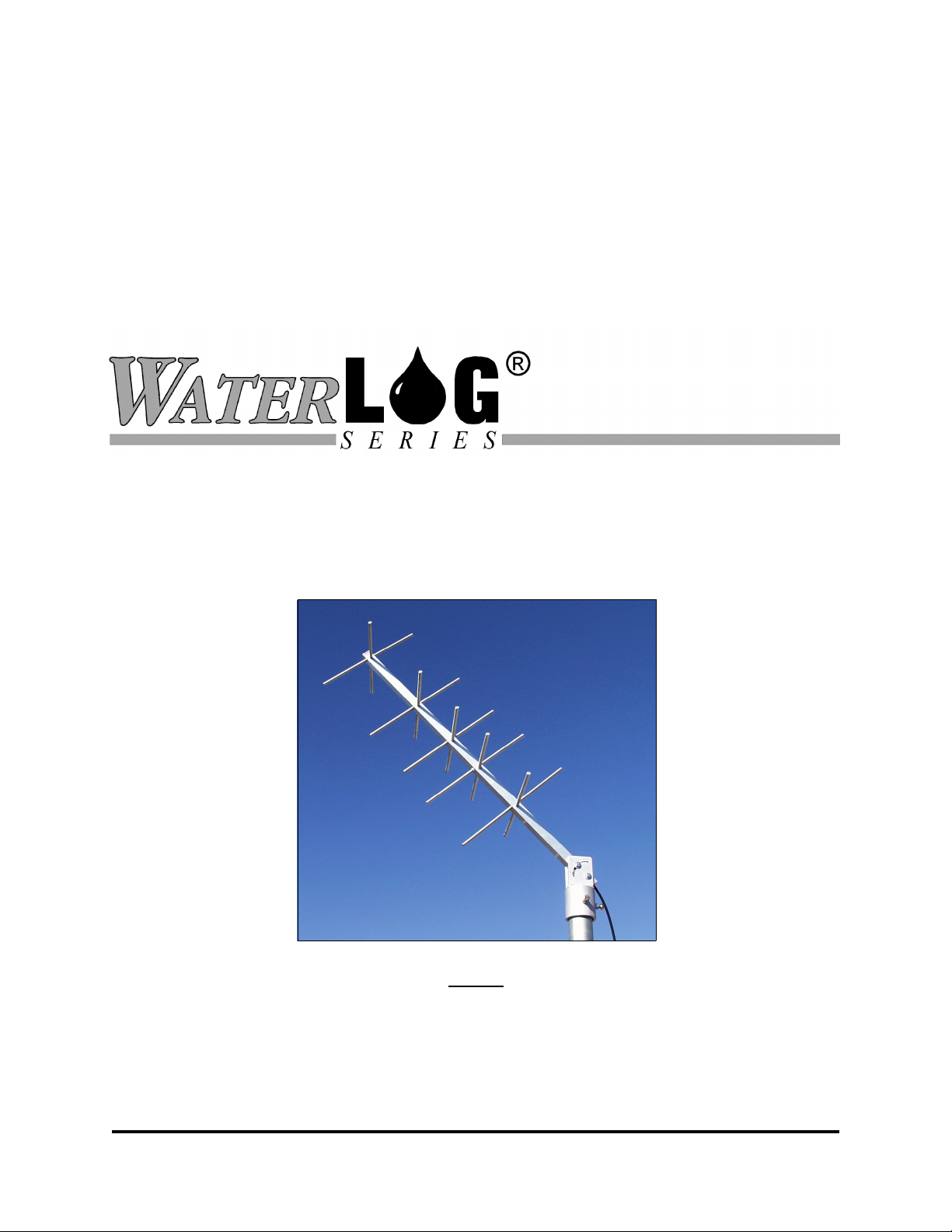
H-223
GOES Satellite Antenna
(401.7 to 402.85 MHz)
Owner's Manual
Version 1.1
NOTICE
This product embodies technology that is confidential and proprietary technology of DESIGN ANALYSIS ASSOCIATES, INC.,
and which is protected by United States copyright laws and international copyright treaty provisions, and/or by contract and
applicable laws of trade secrecy. These include all Software, Printed Circuit Board Artwork, Schematic Diagrams, and
Technologies applied therein. The enclosure encasing the electronics of this instrument may not be opened without written
consent of DESIGN ANALYSIS ASSOCIATES, INC., and any attempt to do so without such written authorization constitutes a
breach of contract and will also void any applicable warranty for the product.
75 West 100 South, Logan, Utah 84321 Phone: (435) 753-2212 Fax: (435) 753-7669 Web: http://www.waterlog.com E-mail: waterlog@waterlog.com
D E S I G N A N A L Y S I S A S S O C I A T E S , I N C .
Page 2

75 West 100 South, Logan, Utah 84321 Phone: (435) 753-2212 Fax: (435) 753-7669 Web: http://www.waterlog.com E-mail: waterlog@waterlog.com
D E S I G N A N A L Y S I S A S S O C I A T E S , I N C .
Page 3

User Agreement/
W
ATER
1. NATURE OF THE PRODUCT
This agreement accompanies an antenna assembly comprising circuitry and other electronic equipment
in an enclosed housing, and packaged together with written instructional materials. The packaged
electronic circuitry and instructional materials herein are collectively referred to as the “PRODUCT.”
The PRODUCT is made available from DESIGN ANALYSIS ASSOCIATES, INC., of 75 West 100
South, Logan, Utah 84321 (hereinafter referred to as “DESIGN ANALYSIS”), and contains information
and embodies technology that is confidential and proprietary to DESIGN ANALYSIS, and the
availability and use of the PRODUCT is extended to you, the USER, solely on the basis of the terms of
agreement which follow.
2. ACKNOWLEDGMENTS BY USER
Opening the package which encloses the accompanying PRODUCT indicates your acceptance of the
terms and conditions of this agreement and constitutes an acknowledgment by you of the confidential and
proprietary nature of the rights of DESIGN ANALYSIS in the PRODUCT.
3. DUTIES OF YOU, THE USER
In consideration for the access to and use of the PRODUCT extended to you by DESIGN ANALYSIS
and to protect the confidential and proprietary information of DESIGN ANALYSIS, USER agrees as
follows:
LOG® Warranty
(a) USER agrees that they will not remove from the exterior of the housing of the PRODUCT any
safety warnings or notices of proprietary interest placed thereon by DESIGN ANALYSIS.
(b) USER agrees that they shall not disassemble or otherwise reverse engineer the PRODUCT.
(c) USER agrees to treat the PRODUCT with the same degree of care as USER exercises in relation to
their own confidential and proprietary information.
4. TERM
USER may enjoy these rights only as long as their possession of the PRODUCT shall continue to be
rightful. These rights will cease if the PRODUCT is returned to DESIGN ANALYSIS under the terms of
any redemption offer, warranty, or money-back guarantee, or if USER transfers the PRODUCT to
another party on terms inconsistent with this agreement.
5. LIMITED WARRANTY
(b) What is Covered
DESIGN ANALYSIS warrants that for a period of twelve months from the time of purchase the
functions to be performed by the PRODUCT will be substantially in compliance with USER
documentation. DESIGN ANALYSIS also warrants that the PRODUCT will be free from
defects in materials and workmanship for a period of ONE YEAR from the date of purchase.
(b) What USER Must Do
If the product fails to satisfy the above warranty, USER must notify DESIGN ANALYSIS in
writing within the applicable period specified above and reasonably cooperate with the directions
they received from DESIGN ANALYSIS.
H-3611
User Agreement/W
ATER
LOG® Warranty W-1
Page 4

(c) What DESIGN ANALYSIS Will Do
DESIGN ANALYSIS will repair the PRODUCT or will endeavor to provide a replacement of
same within a reasonable period of time. In the event that DESIGN ANALYSIS is unable to
make the necessary repairs or replacement within a reasonable period of time, the original
purchase price will be refunded upon the return of the PRODUCT to DESIGN ANALYSIS.
(d) Limitations
(i) THE ENTIRE REMEDY FOR BREACH OF THIS LIMITED WARRANTY SHALL
BE LIMITED TO REPLACEMENT OF THE DEFECTIVE PRODUCT OR
REFUNDING OF THE PURCHASE PRICE, AS SET FORTH ABOVE. IN NO
EVENT WILL THE LIABILITY OF DESIGN ANALYSIS TO USER OR TO ANY
OTHER PARTY EXCEED THE ORIGINAL PURCHASE PRICE OF THE PRODUCT,
REGARDLESS OF THE FORM OF THE CLAIM.
(ii) EXCEPT FOR THE EXPRESS WARRANTIES ABOVE, DESIGN ANALYSIS
SPECIFICALLY DISCLAIMS ALL OTHER WARRANTIES, INCLUDING,
WITHOUT LIMITATION, ALL IMPLIED WARRANTIES OF MERCHANTABILITY
AND FITNESS FOR A PARTICULAR PURPOSE.
(iii) UNDER NO CIRCUMSTANCES WILL DESIGN ANALYSIS BE LIABLE FOR
SPECIAL, INCIDENTAL, CONSEQUENTIAL, INDIRECT, OR ANY OTHER
DAMAGES OR CLAIMS ARISING FROM THE USE OF THIS PRODUCT, THIS
INCLUDES LOSS OF PROFITS OR ANY OTHER COMMERCIAL DAMAGES,
EVEN IF ADVISED OF THE POSSIBILITY OF SUCH DAMAGES. IN NO EVENT
WILL DESIGN ANALYSIS BE LIABLE FOR ANY CLAIMS, LIABILITY, OR
DAMAGES ARISING FROM MODIFICATION MADE THEREIN, OTHER THAN
BY DESIGN ANALYSIS.
(iv) THIS LIMITED WARRANTY GIVES USER SPECIFIC LEGAL RIGHTS. USER
MAY ALSO HAVE OTHER RIGHTS WHICH VARY FROM STATE TO STATE.
SOME STATES DO NOT ALLOW LIMITATIONS ON HOW LONG AN IMPLIED
WARRANTY LASTS OR THE EXCLUSION OF INCIDENTAL OR
CONSEQUENTIAL DAMAGES, SO THOSE LIMITATIONS OR EXCLUSIONS
MAY NOT APPLY.
6. GOVERNING LAW
This Agreement and its validity and interpretation shall be governed by the laws of the State of Utah,
notwithstanding any choice of law rules of Utah or any other state or jurisdiction.
W-2 User Agreement/W
ATER
LOG® Warranty
H-4161
Page 5

Assembly &
Installation Instructions
1.0 Introduction
The W
ATER
LOG® H-223 is a rugged, high-gain Yagi antenna designed for use with fixed location GOES
Satellite Data Collection Platforms. The antenna has two 5-element Yagi antennae mounted on an
extruded aluminum boom. The one-piece reflector and director elements lock firmly into place with a
unique ½-turn cam-lock mechanism.
Key features include:
Rugged, heavy duty construction
High gain
Circular polarization
Fully adjustable mount fits on a 2-inch pipe mast
Can be disassembled for easy transport and shipping
2.0 Assembly
The W
ATER
LOG® H-223 antenna is shipped disassembled in a 4" x 4" x 48" box. You will need a 6-inch
adjustable wrench and a pair of pliers to assemble the antenna. Unpack and familiarize yourself with the
parts. You should have:
Quan Description
1 Adjustable mount, complete with 2 setscrews, 2- bolts, 2-nuts and 4-washers
1 1" square x 38" boom
4 Dipole elements (7" long, with threaded stud)
1 Reflector-A element (14-3/4" long, with eccentric cam)
1 Reflector-B element (14-3/4" long, with round notch)
3 Director-A elements (13-1/4" long, with eccentric cam)
3 Director-B elements (13-1/4" long, with round notch)
Refer to the assembly drawing for the proper location of each element. Install the elements as follows:
Install three sets of director elements (13-1/4" long)
Install one set of reflector elements (14-3/4" long)
Install four dipole elements (7" long with threaded stud)
H-223
Assembly & Installation Instructions 1-1
Page 6

2.1 Install the Director and Reflector Elements
Element Cam-Lock
The Yagi elements are installed in pairs using a cam-lock mechanism to rigidly lock each element in
place. Each pair consists of one element with an eccentric cam and the second with a small round notch
in the center. Follow Steps 1 thru 3 to install the three 13-1/4" long director pairs and the 14-3/4" long
reflector pair.
Step 1
Insert Cam Element
Step 2
Insert Notched Element
Rotate Cam Element
Step 3
into locked position
Step 1: Insert the element with the cam into the boom until the cam
is in the center of the boom. Rotate the cam until the side passage is unobstructed. Do not attempt to
insert the notched element first, the 2nd element will not slide past the notch.
Step 2: While holding the first element in place, insert the second element (with the round notch) into the
boom and rotate it until the notch is aligned with the cam. Slide the notched element into the boom until
the notch is approximately centered inside the boom. By hand, rotate the cam element until the cam rubs
against the notched element. Slide the notched element back and forth until you feel the cam drop into
the notch. Continue to rotate the cam element by hand until it turns approximately 30 degrees. If it
won’t turn 30 degrees it is not properly aligned with the notch in the other element.
1-2 Assembly & Installation
H-223
Page 7

Step 3: With an adjustable wrench, continue to rotate the cam element past the 30 degree point until the
wrench flats are parallel with the boom. At this point the two elements will be firmly locked into place.
When installing the two reflector elements, you will need to work the elements past the coax leadwire
inside the boom. The leadwire is routed in one corner of the boom. Insert the reflector elements first thru
the hole in the boom opposite of the leadwire. This will provide leverage while working the element past
the leadwire into the opposite hole. After installing the director and reflector element pairs, make certain
the wrench flats of all 4 cam elements are parallel to the boom.
Step 4: Install the four dipole elements. The dipole elements are 7" long and have a threaded stud on one
end. Screw the threaded studs into the boom and tighten lightly with a pair of pliers. Do not over
tighten. Over tightening may strip out the threads in the plastic insulator inside the boom.
Install the four Dipole Elements
H-223
Step 4
Assembly & Installation Instructions 1-3
Page 8

3.0 Installation
The adjustable mount is designed to fit over a standard 2-inch pipe mast. It works in both the vertical
and horizontal positions. The antenna must have a clear, unobstructed view of the satellite. Mount the
antenna above the reach of vandals and away from pipes, wires and other metal obstructions. The
antenna should be mounted at least 6 feet (2 wavelengths) above the earth to provide proper impedance
matching. Install the antenna with the side marked “this side up” appropriately.
Rotate the adjustable mount to the desired azimuth position. Tighten the two setscrews against the pipe
mast, then tighten the two jam-nuts to prevent the setscrews from working loose. Raise the boom to the
desired elevation, then tighten the two 1/4" hex bolts on the mount. Strap the coax cable to the pipe mast
as needed to prevent wind damage.
4.0 Lead Wire
Keep the lead wire as short as possible. Use RG-58 (or preferably LMR-240) 50 ohm coax cable. For a
lead wire longer than 20 feet use LMR-400 or similar low loss cable. Install a lightning arrester or other
protective device in the gauge station. Use a drip-loop or roof jack to prevent water from following the
coax into the gauge station.
1-4 Assembly & Installation
H-223
Page 9

H-223
Assembly & Installation Instructions 1-5
 Loading...