


300
Table of contents
 Loading...
Vital Signs Monitor
300 Series
Directions for use
Software version 1.2X

ii Welch Allyn Vital Signs Monitor 300 Series
© 2014 Welch Allyn. All rights are reserved. To support the intended use of the product described in this
publication, the purchaser of the product is permitted to copy this publication, for internal distribution only,
from the media provided by Welch Allyn.
Welch Allyn assumes no responsibility for any injury to anyone, or for any illegal or improper use of the
product, that may result from failure to use this product in accordance with the instructions, cautions,
warnings, or statement of intended use published in this manual.
Welch Allyn is a registered trademark of Welch Allyn.
Nellcor is a registered trademark of Nellcor Puritan Bennett Inc.
Software in this product is copyright Welch Allyn or its vendors. All rights are reserved. The software is
protected by United States of America copyright laws and international treaty provisions applicable
worldwide. Under such laws, the licensee is entitled to use the copy of the software incorporated with
this instrument as intended in the operation of the product in which it is embedded. The software may not
be copied, decompiled, reverse-engineered, disassembled or otherwise reduced to human-perceivable
form. This is not a sale of the software or any copy of the software; all right, title and ownership of the
software remains with Welch Allyn or its vendors.
For information about any Welch Allyn product, visit www.welchallyn.com/en/about-us/locations.html.
DIR 80019418 Ver A
Welch Allyn Protocol Inc.
8500 SW Creekside Place
Beaverton, OR 97008
USA
www.welchallyn.com
Regulatory Affairs Representative
Welch Allyn Limited
Navan Business Park
Dublin Road, Navan
County Meath, Republic of Ireland

Contents
1 - General Information ......................................1
iii
About This Manual ................................................1
Intended Use ....................................................1
Symbols ........................................................2
Product Overview .................................................3
Warnings and Cautions.............................................4
Displays, Indicators, Controls, and Connections ..........................6
2 - Setup ..................................................9
Connections .....................................................9
Power On, Power-on Self-Test, and Power Off .........................15
Configuring Operating Parameters ...................................16
3 - Patient Monitoring ......................................29
Monitoring Blood Pressure .........................................29
Monitoring Pulse Rate ............................................36
Monitoring SpO2.................................................37
Monitoring Temperature...........................................40
4 - Alarms and Alerts .......................................51
Responding to a Patient Alarm ......................................51
Responding to an Equipment Alert ...................................52
Alarm Indicators .................................................54
Setting Alarms ..................................................54
Nurse Call ......................................................57
Error Codes.....................................................58
5 - Reviewing Patient Data...................................59
Displaying Stored Patient Data ......................................59
Printing Patient Data ..............................................59
Erasing Patient Data ..............................................65
Replacing the Printer Paper Supply ..................................66
6 - Operator Maintenance ...................................67
Cleaning .......................................................67
Storage ........................................................67
Recycling Monitor Components .....................................68

iv Contents Welch Allyn Vital Signs Monitor 300 Series
7 - Reference ..............................................69
Battery Operation ................................................69
Monitor Specifications ............................................71
Factory Default Settings ...........................................80
Limited Warranty ..........................................81
Index ....................................................83

1
1
General Information
About This Manual
This manual contains information about the Welch Allyn®Vital Signs Monitor 300 Series
monitor. The series includes the following models:
Model Features Model Features
53000 Standard (NIBP, Pulse Rate, and MAP) 53N00 Standard + Nellcor
5300P Standard + Printer 53NT0 Standard + Nellcor SpO2+ Temperature
530T0 Standard + Temperature 53N0P Standard + Nellcor SpO
530TP Standard + Temperature + Printer 53NTP Standard + Nellcor SpO
All operators must read and understand this manual before using the monitor.
All technicians and other service personnel must read and understand this manual before
attempting to set up, configure, troubleshoot, or service the monitor.
All information in this manual, including the illustrations, is based on a monitor configured
with the Temperature, SpO2, and Printer options. If your monitor configuration lacks any
of these options, then some information in this manual does not apply.
®
SpO
2
+ Printer
2
+ Temperature + Printer
2
Intended Use
The VSM series of monitors are intended to be used by clinicians and medically qualified
personnel for monitoring of noninvasive blood pressure, pulse rate, body temperature,
noninvasive functional oxygen saturation of arteriolar hemoglobin (SpO2), and body
temperature in normal and axillary modes of neonatal, pediatric and adult patients.
The most likely locations for patients to be monitored are general med/surg. floors,
general hospital and alternate care environments. This device is available for sale only
upon the order of a physician or licensed health care professional.
2 Chapter 1 General Information Welch Allyn Vital Signs Monitor 300 Series
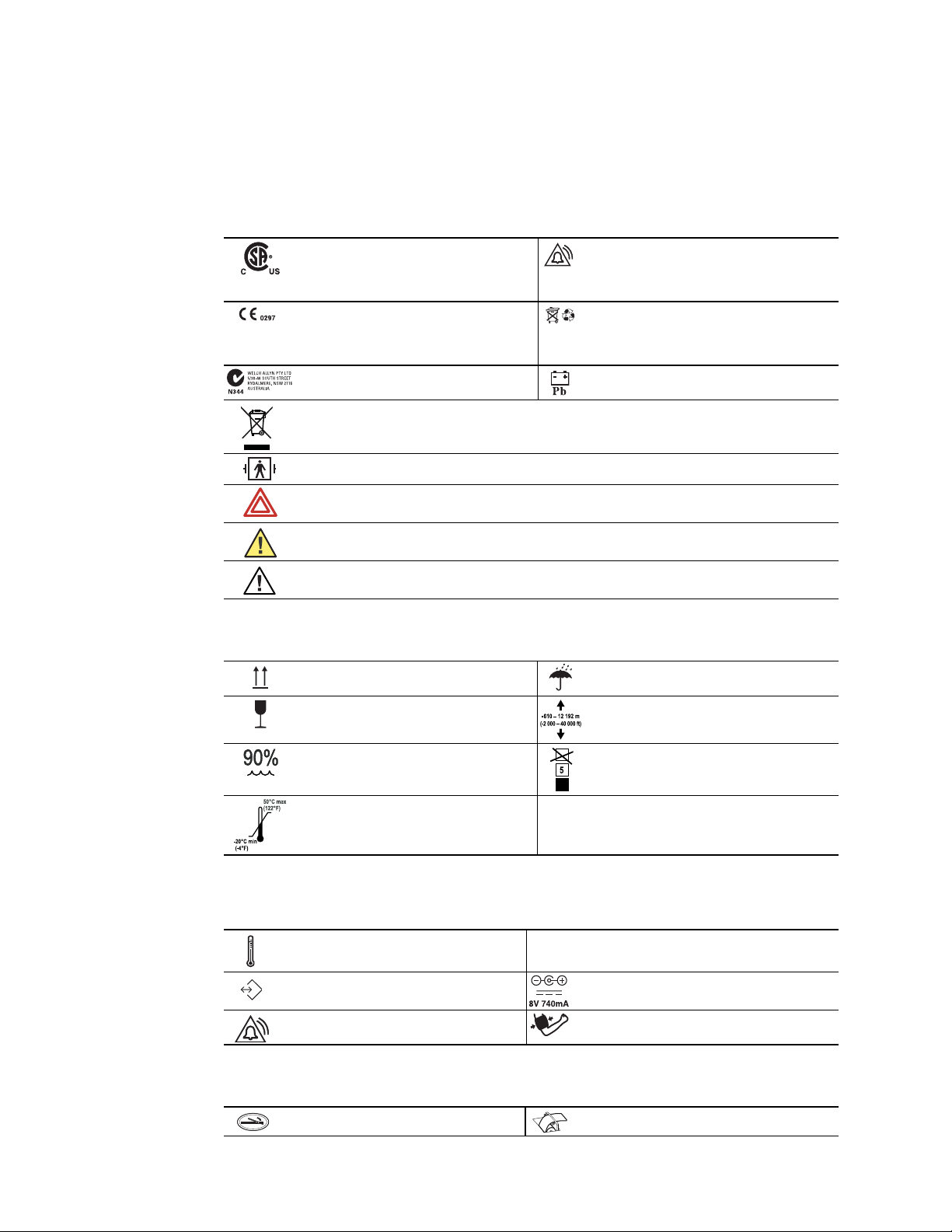
Symbols
The symbols illustrated on the following pages appear on the monitor or in this document.
Table 1. Symbols: Certification and Operation
This device has been tested and certified by
the Canadian Standards Association
International to comply with applicable U.S.
and Canadian medical safety standards.
The CE Mark and Notified Body Registration
Number signify that the device meets all
essential requirements of the European
Medical Device Directive 93/42/EEC.
Australian Registered Importer Sealed lead-acid battery, 6V 4 Ah
Recycle the monitor and battery separately from other disposables. (See “Recycling Monitor Components”
on page 68.)
Patient connections are Type BF, and protected against defibrillation.
WARNING Indicates conditions that could lead to illness, injury, or death.
Caution In this manual, indicates conditions that could damage equipment or other property.
Caution On the product, means “Consult accompanying documentation.”
Table 2. Symbols: Shipping, Storing, and Environment
Keep this end of the package or shipping
crate up.
Fragile contents—handle with care. Do not subject the monitor to altitudes outside
Urgent alarm notification (output to Nurse Call
system)
Recycle used batteries properly and in
accordance with local regulations.
Do not dispose of batteries in refuse containers.
Protect the monitor from exposure to rain.
these limits.
Do not expose the monitor to relative
humidity above this limit.
Do not expose the monitor to temperatures
outside these limits.
Table 3. Symbols: Connectors
Temperature Probe Cable Connector SpO2 SpO
RS232 Cable Connector AC Power Adapter Cable Connector
Nurse Call Cable Connector NIBP Hose Connector
Table 4. Symbols: Printer Door
Press to open the printer door Load paper this direction
Limit stacking to this number of units.
Sensor Cable Connector
2
Directions for Use Chapter 1 General Information 3
ºC
ºF
M
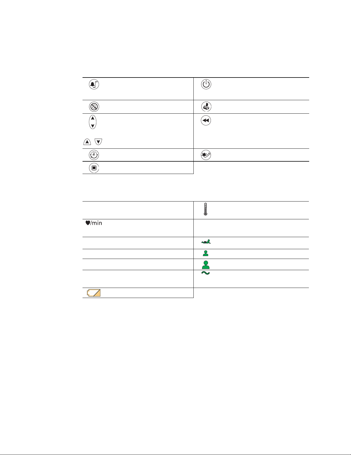
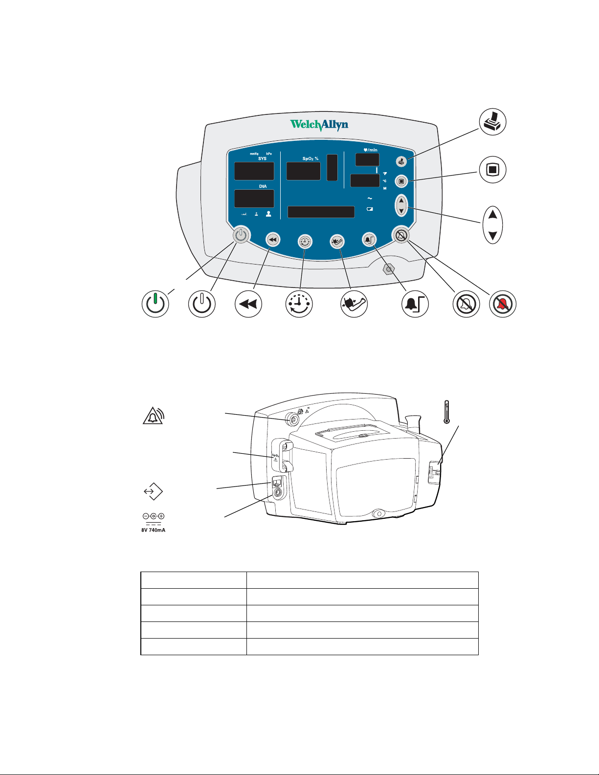
The functions of the monitor front panel controls illustrated here are described in detail
elsewhere in this document.
Table 5. Front Panel Controls
Set alarm limits Power on/off
Silence alarms Print patient data
Scroll up/down
Scroll forward/back
Increase/decrease value
(The scroll icon appears as these two arrows
in the documentation.)
Set an NIBP automatic measurement interval Start/stop an NIBP cycle (AUTO button)
Cycle to the next menu selections
Table 6. Front Panel Displays and Indicators
SYS
Systolic pressure
DIA
SpO2
message
window
Diastolic pressure
Arterial hemoglobin oxygen saturation
Pulse rate pulse
MAP (mean arterial pressure) Neonatal
Degrees Celsius Pediatric
ºC
Degrees Fahrenheit Adult
ºF
Monitored temperature AC power
M
Battery discharged
Review patient data
Temperature
Pulse strength
amplitude
indicator
Battery charging (flashing)
Battery charged (steady)
Product Overview
The monitor can monitor systolic and diastolic noninvasive blood pressure (NIBP), pulse
rate, and MAP (mean arterial pressure). Units configured with the appropriate options can
also simultaneously monitor temperature and SpO2, and can continuously monitor
pulse rate.
All vital-sign measurements are displayed on the front panel of the monitor. These
measurements can also be printed, using the optional integrated thermal printer.
The monitor provides programmable audible and visual alarms and automatic NIBP
measurements at selectable intervals. It can also be configured to provide an alarmactivated Nurse Call function.
Accessory equipment connected to the analog and digital interfaces must be certified to
the respective IEC standards (IEC 60950 for data-processing equipment, IEC 60601-1 for

4 Chapter 1 General Information Welch Allyn Vital Signs Monitor 300 Series
medical equipment). All such configurations must comply with system standard
IEC 60601-1-1.
Caution Anyone connecting additional equipment to the signal input part or
signal output part of this monitor configures a medical system and is
responsible for verifying that the system complies with the requirements of the
system standard IEC 60601-1-1. Changes or modifications not expressly approved
by Welch Allyn could void the purchaser’s authority to operate the equipment.
Warnings and Cautions
All operating and service personnel must be familiar with the information presented here,
and with other warnings and cautions which appear throughout this document.
Warning and caution labels can appear on the monitor, the packaging, the shipping
container, or in this document.
General Warnings
WARNING Many environmental variables, including patient physiology and
clinical application, can affect the accuracy and performance of the device. The
clinician must verify all vital signs information prior to patient intervention.
WARNING The monitor is for use only by medical clinicians. Although this
document might illustrate medical monitoring techniques, the monitor must be
used only by trained clinicians who know how to take and interpret a patient’s
vital signs.
WARNING During defibrillation, keep the defibrillation discharge paddles away
from any conductive parts that might already be in contact with the patient.
WARNING Use only accessories approved by Welch Allyn. Visit
www.welchallyn.com. The use of any other accessories can result in inaccurate
patient data, can damage the equipment, and can void your product warranty.
WARNING Do not operate the monitor in the presence of magnetic resonance
imaging (MRI) or hyperbaric chambers.
WARNING Do not operate the monitor in the presence of a flammable
anesthetic mixture with air, oxygen, or nitrous oxide, or in oxygen-enriched
environments, or in any other potentially explosive environment.
WARNING It is the clinician’s responsibility to set or verify alarm limits
appropriate to each patient.
WARNING Never allow any liquid to enter any monitor connector. If a connector
does come in contact with liquid:
1. Remove the monitor from service.
2. Use warm, dry air to dry the connector.
3. Thoroughly test and verify operation before returning the monitor to service.

Directions for Use Chapter 1 General Information 5
WARNING Do not connect more than one patient to a monitor.
WARNING If the monitor is dropped or damaged, it must be thoroughly tested
by a qualified service person before it is returned to service.
WARNING Periodically check all cords and cables for damage, wear, or fraying;
replace as needed.
WARNING The monitor contains no operator-serviceable parts, other than the
replaceable paper roll.
WARNING If the battery shows any signs of damage, leakage, or cracking, it
must be replaced immediately, by a qualified service person, and only with a
battery approved by Welch Allyn.
WARNING Always recycle batteries according to local regulations. Never
dispose of batteries in refuse containers.
WARNING Do not use the monitor on patients who are linked to a heart
machine or a lung machine.
WARNING Do not use the monitor on patients who are experiencing
convulsions or tremors.
General Cautions
WARNING Do not use the pulse oximeter as a replacement or substitute for
ECG-based arrhythmia analysis.
Caution If the accuracy of any measurement is in doubt, verify the patient’s vital
sign by another method. If the monitor is not measuring accurately, have it
inspected by a qualified service person.
Caution Be sure that the monitor is securely located on a flat surface or properly
suspended by means of appropriate mounting equipment.
Caution Do not autoclave the monitor.
Caution Do not place cups, glasses, or other fluid containers or vessels on the
monitor.
Caution Users should check for audible alarm function every time the VSM 300
is used. During the normal power-up cycle, two audible tones are emitted
immediately after the self-test is complete. If these tones do not sound, the audio
has failed. Remove the device from service and contact Welch Allyn.
The loss of the audible alarm could cause a delay in a clinician learning of an alarm
condition for the following conditions: 1) hypotension or hypertension, 2) low
blood oxygen content (SpO2), 3) low or high pulse rate, 4) other alarm conditions
relating to the loss of monitoring of a patient (e.g., a “sensor off” condition). Such
delay could potentially result in injury to the patient.
6 Chapter 1 General Information Welch Allyn Vital Signs Monitor 300 Series
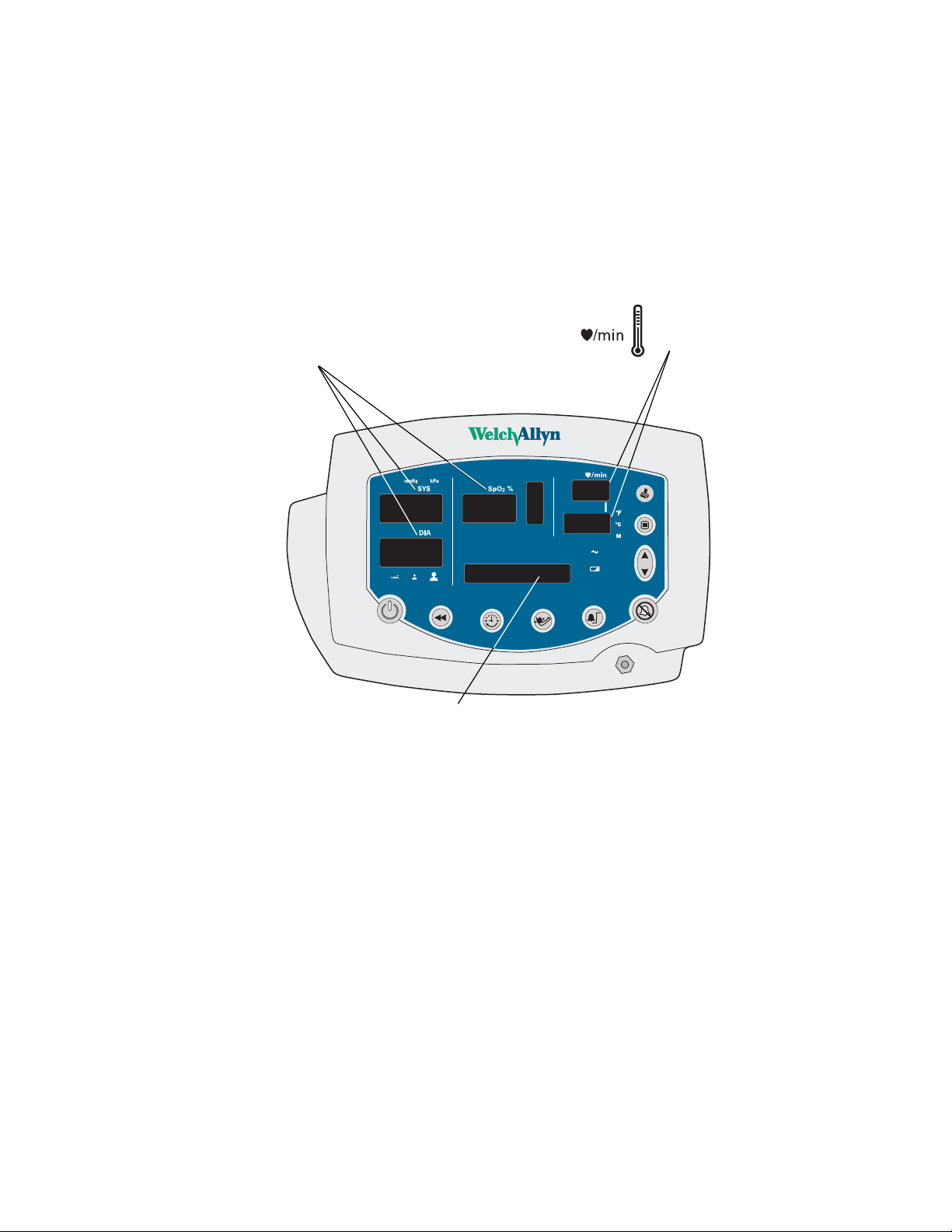
Displays, Indicators, Controls, and Connections
This section describes the measurement displays, status indicators, function controls, and
connections of the monitor.
Numeric Measurement and Message Displays
SYS, DIA, and SpO2.
Displays systolic and diastolic
blood pressure and SpO
related alarm thresholds and
error codes. (See “Error Codes”
on page 58.)
2
,or
Displays pulse rate and
temperature, or related alarm
thresholds and error codes.
(Message window)
Displays the current date and time, MAP measurements, and alarm
thresholds. Displays configuration settings, error codes, software version
numbers, and printer status.
Directions for Use Chapter 1 General Information 7
ºF
M
ºC
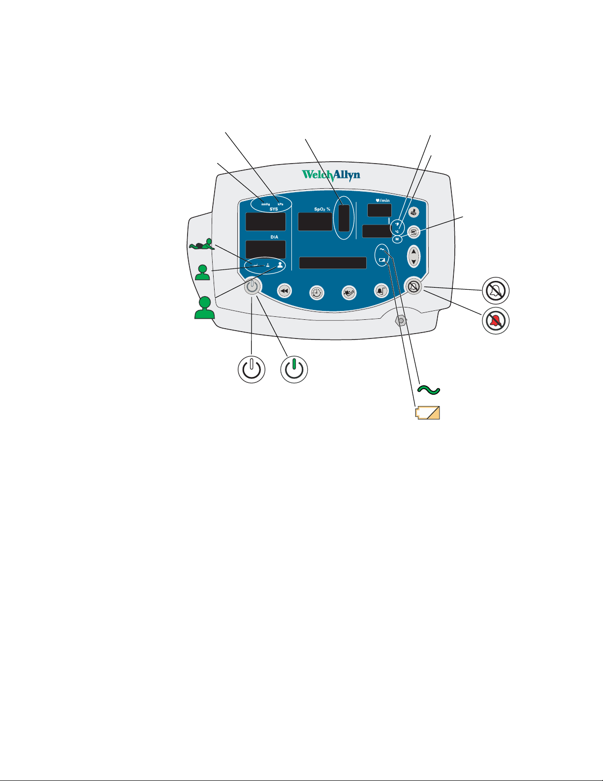
Status Indicators
NIBP Measurement Units
kilopascals
millimeters of
mercury
Patient type
neonate
pediatric
adult
kPa
mmHg
Amplitude Indicator
power
is off
Pulse
power
is on
Temperature Units
degrees Fahrenheit
ºF
degrees Celsius
ºC
Temperature Type
monitored
M
alarms not silenced
alarms silenced
Battery Status
charged ———
charging-----
discharged
8 Chapter 1 General Information Welch Allyn Vital Signs Monitor 300 Series
Function Controls
Print
Menu
Up/Down
Power On/Off
Connections
Power
is on
SpO
2
Power
is off
Nurse Call Cable
Connector
SpO
Sensor Cable
2
Connector
RS232 Cable
Connector
DC Power Cable
Connector
Review
Data
Set NIBP
Interval
30V , 1A Max.
Start/Stop NIBP
(AUTO button)
Set Alarm
Limits
For information on the connections, refer to the following:
AC Power Adapter “Connecting AC Power” on page 9
Temperature Probe “Connecting the Temperature Probe Cable” on page 12
Sensor “Connecting and Disconnecting the SpO2 Sensor Cable” on page 13
SpO
2
NIBP Cuff Hose “Connecting the NIBP Cuff Hose” on page 11
Silence
Alarms
Temperature Probe
Cable Connector
Alarms
Silenced
Nurse Call Cable “Nurse Call” on page 79

9
2
Setup
This chapter describes the set-up procedures for patient monitoring.
Connections
Use the procedures described below to connect components to the monitor.
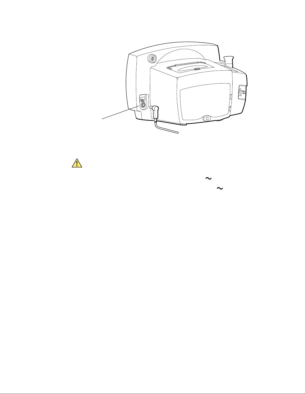
Connecting AC Power
The monitor operates on DC power, supplied by either the internal battery or the AC
power adapter. (For information on the battery, refer to “Battery Operation” on page 69
and “Electrical” on page 74.)
When the AC power adapter is connected, it simultaneously powers the monitor and
charges the internal battery. When the AC power adapter is not connected, the monitor
operates on the internal battery.
WARNING Use only accessories approved by Welch Allyn. Visit
www.welchallyn.com. The use of any other accessories can result in inaccurate
patient data, can damage the equipment, and can void your product warranty.
Caution Using an unqualified power adapter can violate isolation requirements.
To use the AC power adapter:
1. Plug the power adapter into the AC power source.
2. Plug the power adapter connector into the monitor DC port.
10 Chapter 2 Setup Welch Allyn Vital Signs Monitor 300 Series
AC Power
Adapter Port
Use the AC power adapter to fully charge the battery before using the monitor. (This can
take up to 12 hours.)
Caution Fully charge the battery before using the monitor for the first time.
Failure to do so will result in poor battery performance and reduced battery life.
• While the monitor is charging, the AC/charging indicator flashes.
• When the monitor is 90% charged, the AC/charging indicator is steady. To fully
charge the battery, leave the AC power adapter connected for a few more hours.
• After the monitor is fully charged for the first time, the monitor can be powered by the
AC power adapter or by the internal battery.
Directions for Use Chapter 2 Setup 11
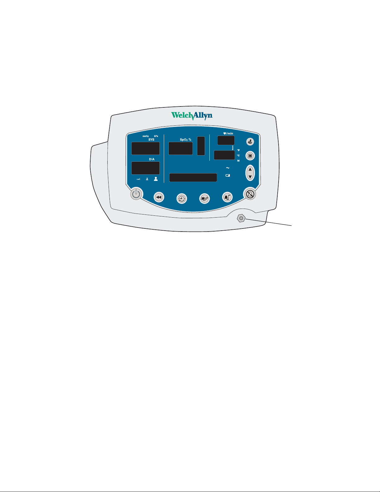
Connecting the NIBP Cuff Hose
Attach the hose to the monitor and the cuff as follows, referring to the illustration below:
1. Screw the hose connector onto the NIBP connector on the monitor.
2. Connect the monitor hose connector to the mating connector on the cuff.
Threaded NIBP
Hose Connector
For information on NIBP measurements, see “Patient Monitoring” on page 29.
12 Chapter 2 Setup Welch Allyn Vital Signs Monitor 300 Series
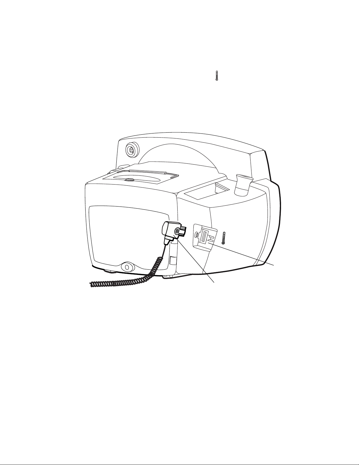
Connecting the Temperature Probe Cable
Follow these steps to connect the temperature probe cable to the monitor.
1. Locate the temperature probe connector port on the back of the monitor.
2. Holding the temperature probe cable connector with the spring tab on the right,
carefully insert it into the monitor temperature probe connector port. The spring tab
clicks out when the connector halves are fully and correctly mated.
3. To disconnect the temperature probe cable, depress the spring tab and withdraw the
cable connector.
TemperatureProbe
Connector Port
TemperatureProbeCable
Connector
For information on temperature measurements, see “Patient Monitoring” on page 29.

Directions for Use Chapter 2 Setup 13
Connecting and Disconnecting the SpO2Sensor Cable
To connect the SpO2 sensor cable:
1. Locate the SpO2sensor cable connector (labeled SpO2) on the side of the monitor.
2. Note the hole patterns of the connector halves, and align the cable connector
accordingly.
Note
3. Carefully insert the SpO2cable connector into the SpO2monitor connector.
Verify that the sensor cable connector has slots on both sides. If the cable
connector has a slot on only one side, then the sensor is not compatible with the
monitor.
The SpO2connectors are notched and flanged to ensure proper fit. If the
connectors do not join easily, stop and verify the following:
• You have the correct SpO2sensor.
• The cable connector is aligned correctly.
If you are using a sensor extension cable, plug the sensor into the extension cable and
plug the extension cable into the monitor.
14 Chapter 2 Setup Welch Allyn Vital Signs Monitor 300 Series
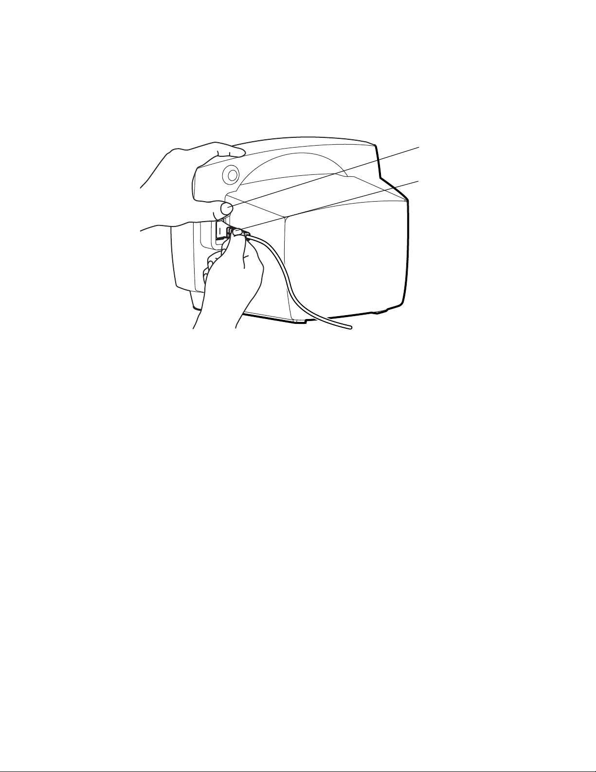
To disconnect the SpO2cable, refer to the instructions shown in the illustration below.
Note
Always grasp the cable by the connector shoulder. Do not pull on the cable itself.
For information on SpO
Thumb presses the uppertab
to free the connector.
Thumb and forefinger grasp the
shoulder of the connector cable
to pull the cable connector out
of the connector port.
measurements, see “Patient Monitoring” on page 29.
2
Directions for Use Chapter 2 Setup 15
ºF
ºF
ºC
M
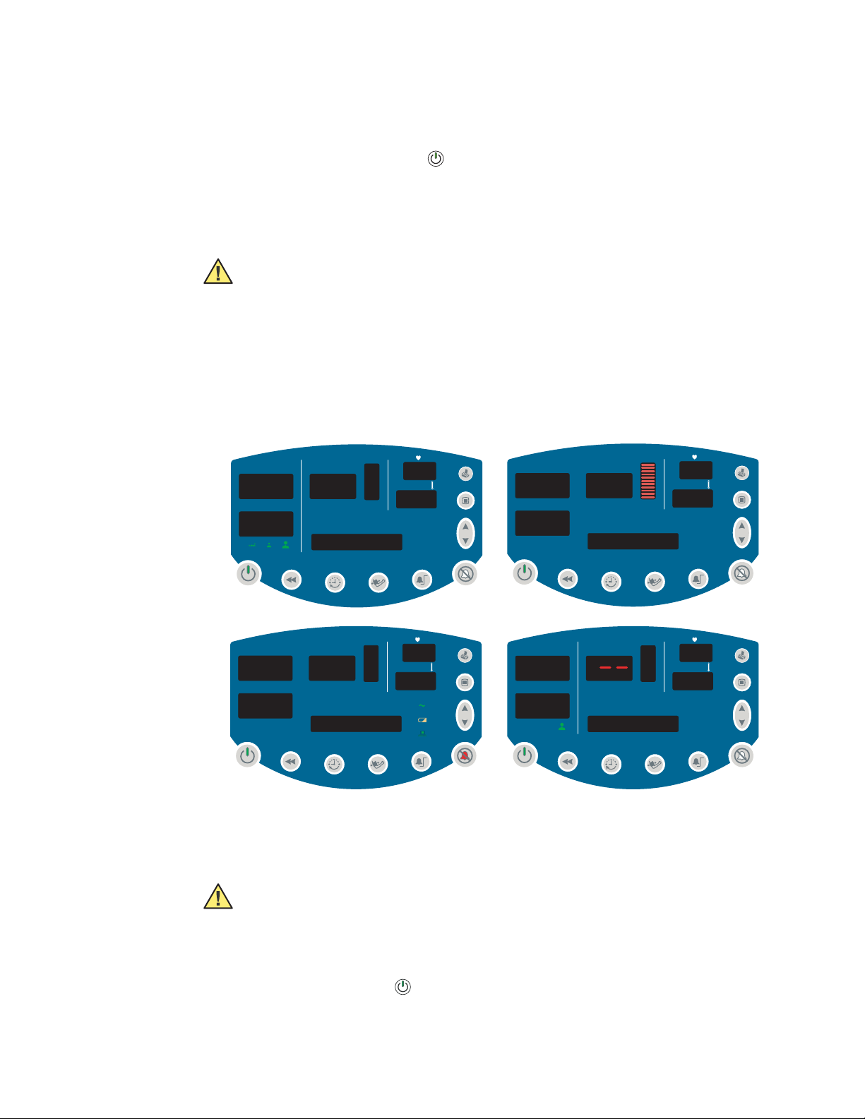
Power On, Power-on Self-Test, and Power Off
When the battery is charged, press to turn on the monitor.
The monitor runs a diagnostic self-test each time it powers up.
• If all tested functions are working normally, the various windows briefly display
start-up values (‘8’ and ‘--’) and a short tone sounds twice.
Caution Users should check for audible alarm function every time the VSM 300
is used. During the normal power-up cycle, two audible tones are emitted
immediately after the self-test is complete. If these tones do not sound, the audio
has failed. Remove the device from service and contact Welch Allyn.
The loss of the audible alarm could cause a delay in a clinician learning of an alarm
condition for the following conditions: 1) hypotension or hypertension, 2) low
blood oxygen content (SpO2), 3) low or high pulse rate, 4) other alarm conditions
relating to the loss of monitoring of a patient (e.g., a “sensor off” condition). Such
delay could potentially result in injury to the patient.
mmHg
SYS
8.8.8
DIA
8.8.8
kPa
.
.
SpO2 %
****************
/min
SYS
SpO2 %
18.8
DIA
****************
.
/min
12
ºF
ºC
34
mmHg
SYS
0
DIA
SpO2 %
/min
0
ºF
SYS
DIA
SpO2 %
/min
8.8.8
1.8.8.8
.
.
0
****************
• If the self-test fails, an error code appears in the SYS window.
When the self-test is complete, the software version appears briefly in the message
window, followed by the current time of day.
00:00:45
Caution Always observe the monitor during power-up. If any display fails to
illuminate properly, or if an error code appears in the systolic window, inform your
biomedical engineering department immediately, or call your nearest Welch Allyn
Customer Service or Technical Support facility. Do not use the monitor until the
problem is corrected.
To shut off the monitor, press .
Note
Shutting off the monitor erases all stored patient data but does not erase settings
or configuration parameters.
16 Chapter 2 Setup Welch Allyn Vital Signs Monitor 300 Series
ºF
M
Configuring Operating Parameters
You can change several monitor operating parameters. When changed, these settings
become the default power-up settings.
How to Use the Menu System
The monitor menu system contains three sets of menus—settings, configuration,
and service.
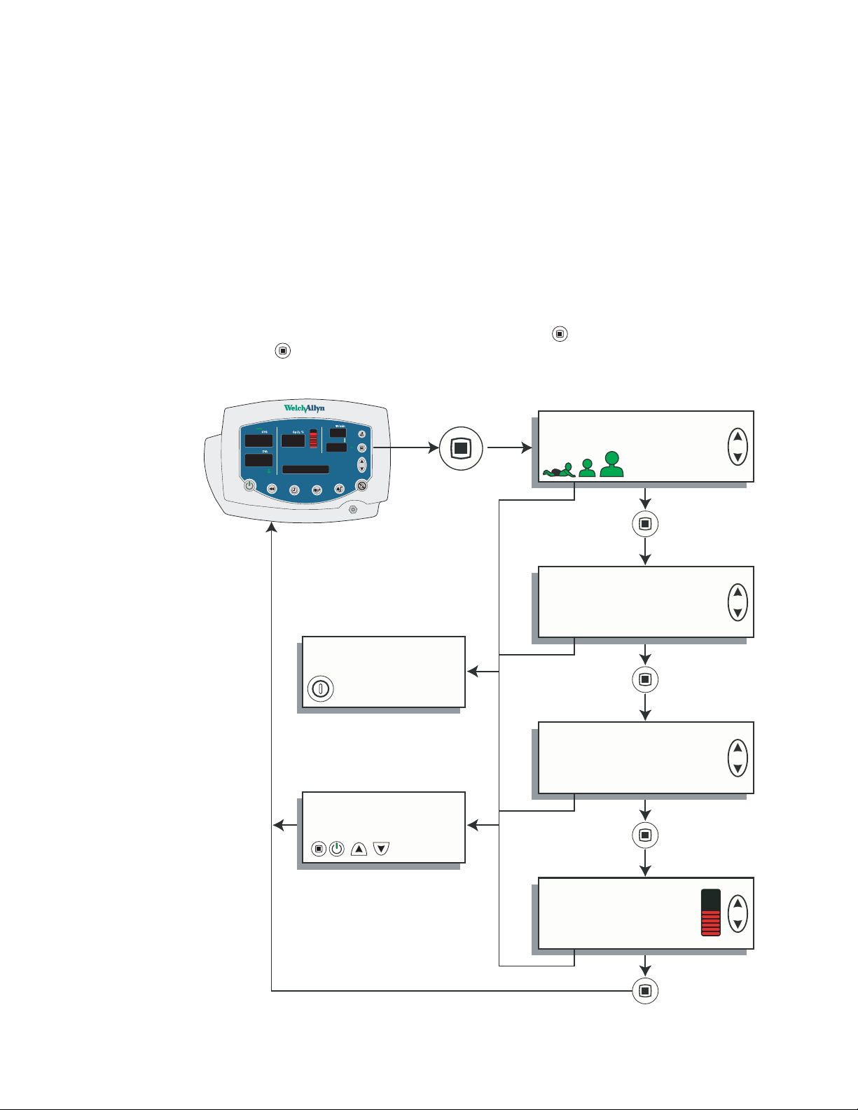
Settings Menu
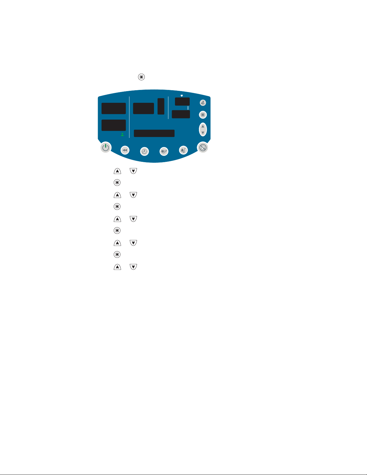
Access the settings menu by pressing the menu button while in normal operation.
Then press repeatedly to reach the setting of interest.
Settings Menu
128
71
98
54
37.0
MAP 90mmHg
Power Off - all values saved
except target inflation pressure
No action for 10 seconds
or
Press any button other than
Patient Type
Target Cuff Inflation Pressure
Temperature Units
Temperature Type
ºF
ºCºCM
Pulse Tone Volume

Directions for Use Chapter 2 Setup 17
ºFºFºFMM
ºCºCºCMM
Use the settings menu to select and set the following parameters:
Patient Type Neonate Term birth through 28 days, or up to 44 gestational weeks
Pediatric 29 days through 12 years
Adult 13 years and older
Target Pressure The initial cuff inflation pressure (set individually for each patient type)
Temp Modes Fahrenheit Predictive
Pulse Tone Volume From 0 (silent) to 5 (loudest)
ºF
Fahrenheit Monitored
Celsius Predictive
ºC
Celsius Monitored
To change a settings parameter:
1. Select the parameter as indicated above.
2. Change the value by pressing or .
3. Set the displayed new value either by doing nothing for 10 seconds or by pressing any
button other than or . If you press a function button (such as ), the monitor
returns to normal operation with that function ( ) activated.
18 Chapter 2 Setup Welch Allyn Vital Signs Monitor 300 Series
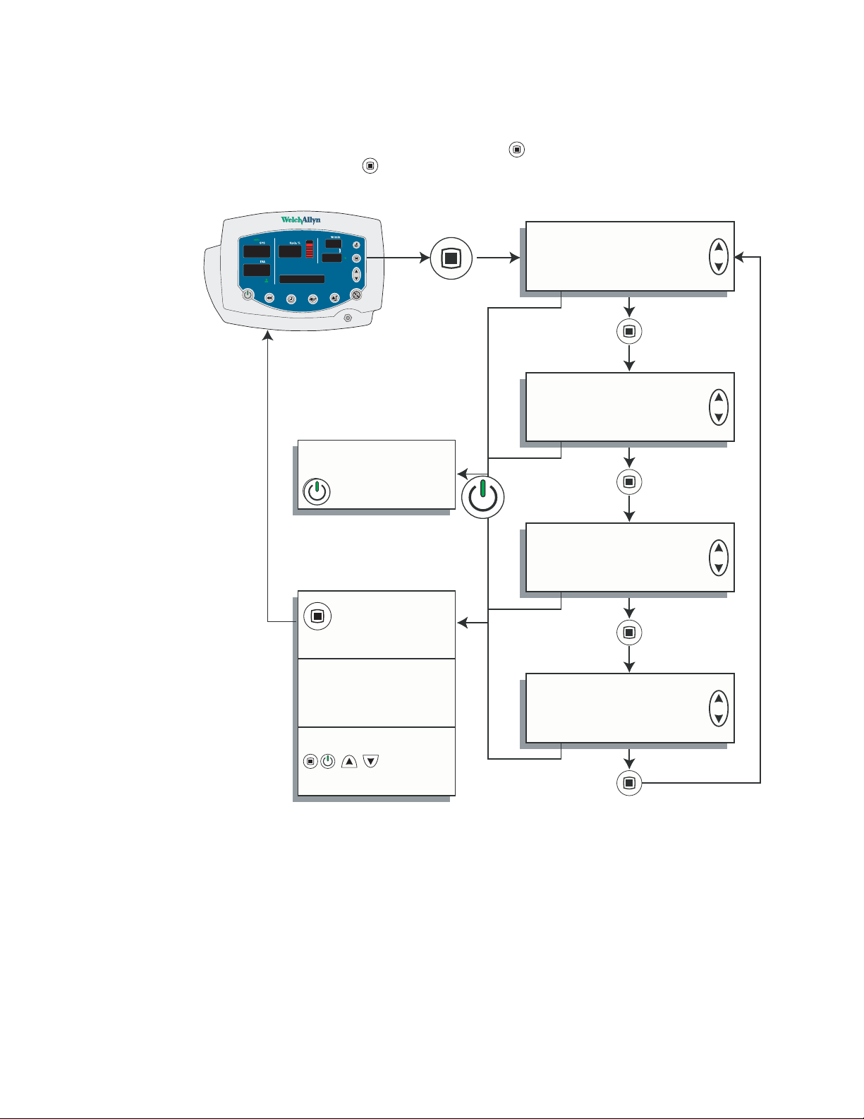
Confi
Configuration Menu
The configuration menu is accessed by pressing and keeping it depressed for three
seconds. You then press repeatedly until you reach the setting of interest.
gurationMenu
128
71
98
54
37.0
MAP 90 kPa
Press and hold
for 3 seconds
Power Off - all values saved
Press and hold for 3
seconds
Set Time and Date
MAP
Enable
Disable
NIBP Units
mmHg
kPa
No action for 10 seconds
Press any button other than
Print
Stream
Batch

Directions for Use Chapter 2 Setup 19
Use the configuration menu to select and set the following parameters:
Time and Date hour
MAP Measurement Enabled
Blood Pressure
Measurement Units
Print Mode Batch
minute
year
month
day
Disabled
mmHg (millimeters of mercury)
kPa (kilopascals)
Stream
To change a configuration parameter:
1. Select the parameter as indicated above.
2. Change the value by pressing or .
3. Set the displayed new value either by doing nothing for 10 seconds or by pressing any
button other than or . If you press a function button (such as ), the monitor
returns to normal operation with that function ( ) activated.
20 Chapter 2 Setup Welch Allyn Vital Signs Monitor 300 Series
ºF
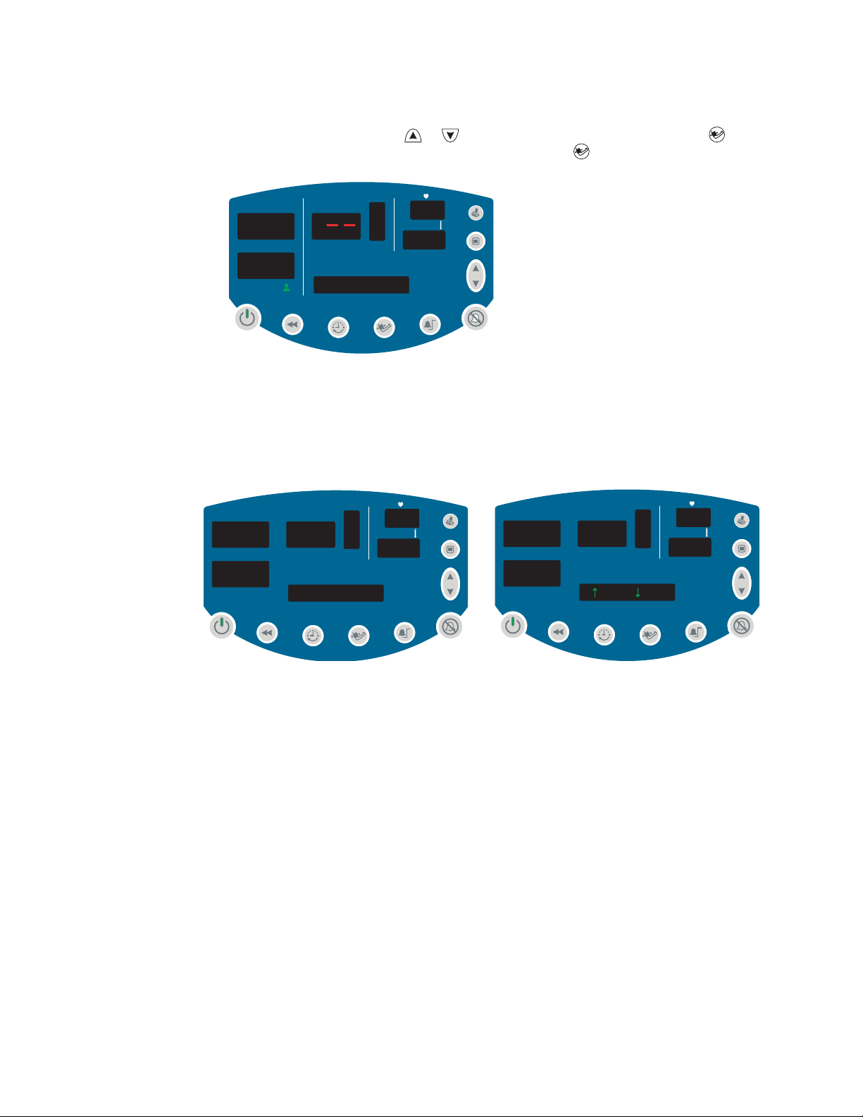
Changing the Time and Date
Follow these steps to change the time and date settings of the monitor internal clock.
1. Press and hold for 3 seconds. SET HOUR XX appears in the message window.
mmHg
SYS
SpO2 %
DIA
SET HOUR 00
/min
ºF
2. Press or as needed to change XX to the current hour.
3. Press once to set the hours and change the display to SET MINUTE XX.
4. Press or as needed to change XX to the current minute.
5. Press once set the minutes and to change the display to SET YEAR XX.
6. Press or as needed to change XX to the current year.
7. Press once to set the year and change the display to SET MONTH XXX.
8. Press or as needed to change XXX to the current month.
9. Press once to set the month and change the display to SET DAY XX.
10. Press or as needed to change XX to the current day.
Directions for Use Chapter 2 Setup 21
ºF
11. To save the displayed time and date settings, either do nothing for 10 seconds or
press any button other than or . If you press a function button (such as ), the
monitor returns to normal operation with that function ( ) activated.
mmHg
SYS
SpO2 %
0
DIA
/min
0
ºF
0
09:24:17
You cannot change the date and time while memory contains stored vital-signs data. If
you attempt to change the date and time setting while data is stored, the question
ERASE DATA? appears in the message window. If you confirm the data erasure, the
monitor erases the data from memory and returns you to the date-set function. If
you select NO, the stored data is retained in memory and the monitor returns to
normal operation.
SYS
DIA
SpO2 %
ERASE DATA?
/min
SYS
SpO2 %
DIA
= YES = NO
/min
22 Chapter 2 Setup Welch Allyn Vital Signs Monitor 300 Series
ºF
ºF
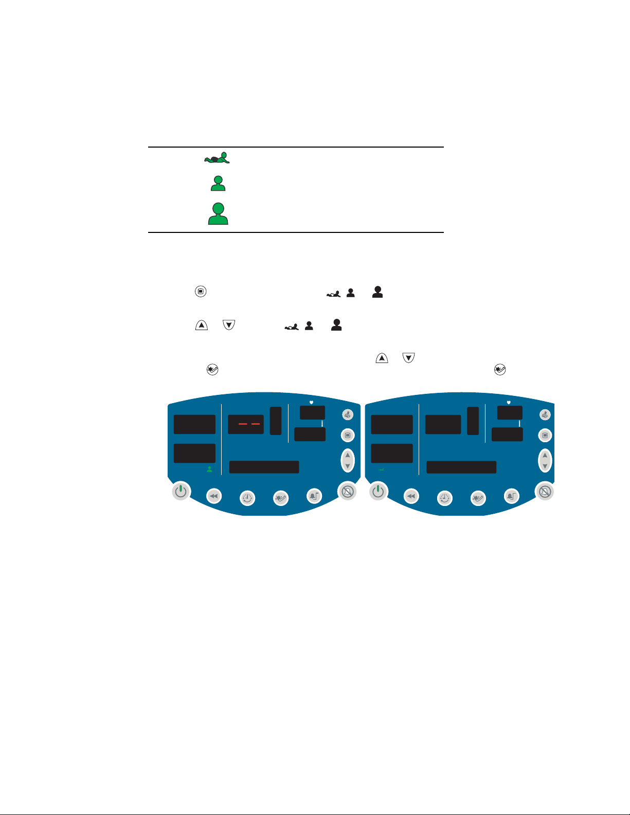
Changing the Patient Type
The age range for each patient type is defined as follows:
Neonatal Term birth through 28 days, or up to 44 gestational weeks
Pediatric 29 days through 12 years
Adult 13 years and older
Default setting: ADULT.
Follow these steps to change the patient type setting.
1. Press . The current patient type ( , , or ) appears below the DIA window, and
NEONATE, PEDIATRIC,orADULT appears in the message window.
2. Press or to display , , or .
3. To select the displayed patient type and return to normal operation, either do nothing
for 10 seconds or press any button other than or . If you press a function button
(such as ), the monitor returns to normal operation with that function ( ) activated.
mmHg
SYS
DIA
0
SpO2 %
/min
0
mmHg
SYS
ºF
DIA
SpO2 %
/min
ºF
0
ADULT
Changing the patient type has the following effects:
• Alarm limits are reset to the default limits for the new patient type
• Cuff inflation target pressure is reset to the default for the new patient type
If you cycle through the patient types but do not change the setting, the alarm limits and
the cuff inflation target pressure settings do not change.
NEONATE
Directions for Use Chapter 2 Setup 23
ºF
ºF
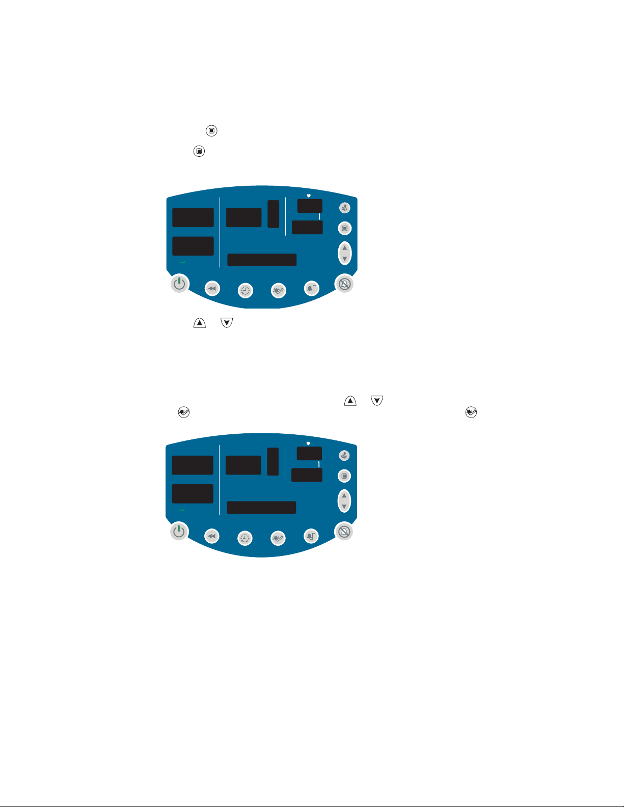
MAP Measurement Enable and Disable
Default setting: MAP ENABLED for neonate; MAP DISABLED for adult and pediatric.
1. Depress for 3 seconds. SET HOUR XX appears in the message window.
2. Press repeatedly until MAP ENABLED or MAP DISABLED appears in the
display window.
mmHg
SYS
SpO2 %
DIA
/min
ºF
MAP DISABLED
3. Press or to enable or disable MAP measurement.
Note
If you change the MAP enabled/disabled setting, refer to “How Changing the
Patient Type Affects MAP Defaults” on page 36.
4. To select the displayed state and return to normal operation, either do nothing for 10
seconds or press any button other than or . If you press a function button (such
as ), the monitor returns to normal operation with that function ( ) activated.
mmHg
SYS
SpO2 %
DIA
/min
ºF
MAP ENABLED
For information about MAP measurements, see “Patient Monitoring” on page 29.
Loading...