


Volvo Trucks North America, Inc.
Greensboro, NC USA
Service Bulletin
Trucks
This Service Bulletin replaces Service Bulletin 371–44, |
Date |
Group |
No. |
Page |
|
12.2004 |
371 |
44 |
1(25) |
||
“Data Links, Fault Tracing” (11.2002), publication number |
|||||
|
|
|
|
||
PV776–TSP177224. |
|
|
|
|
Data links, fault tracing
VN, VHD VERSION2
From build date 11.2002
Data Links, Fault Tracing
T3015830
Contents
“Data Links, Fault Tracing” page 3 “Terminating Resistor, Checking” page 13 “J1708 Information Link, Fault Tracing” page 14 “J1939 Control Link, Fault Tracing” page 16
PV776-20 020644 |
USA16430 |
Volvo Trucks North America, Inc. |
Date |
Group |
No. |
Page |
Service Bulletin |
12.2004 |
371 |
44 |
2(25) |
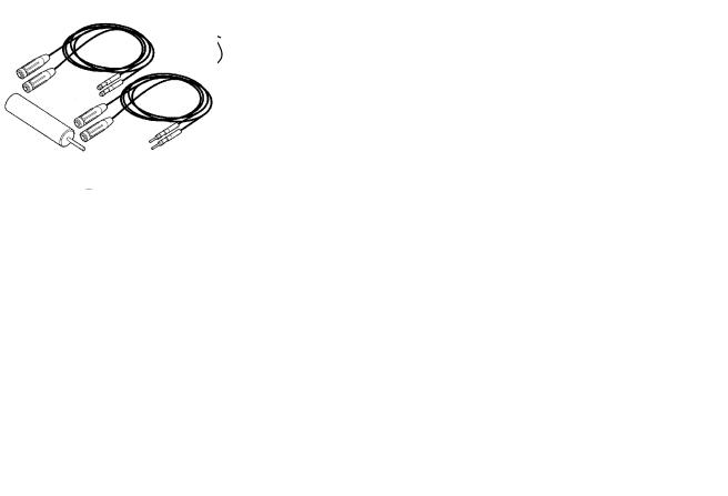
Tools
Special Tools
9990008 |
J-38125-8 |
J-39200 |
Set of Test Pins |
Wire Crimpers |
Digital Multimeter (DMM) |
9998699 |
9990062 |
J-42449 |
Breakout Box 62 Pin |
Cable Extension |
JAE Terminal Probes |
Volvo Trucks North America, Inc. |
Date |
Group |
No. |
Page |
Service Bulletin |
12.2004 |
371 |
44 |
3(25) |
Troubleshooting
Data Links, Fault Tracing
General Troubleshooting Procedures
The control units share information via two different data links “information link SAE J1587/1708” and “control link SAE J1939”
The messages on the SAE J1587/1708 information link are for example, fault codes and warning messages. In some cases the SAE J1587/1708 link also acts as a reserve for SAE J1939. VCADS Pro only communicates on SAE J1587/1708.
SAE J1939 is a faster link which means more data can be transmitted. SAE J1939 is used to transmit data that the system uses for control functions, for example, engine speed (rpm).
Checks:
•
•
“J1708 Information Link, Fault Tracing” page 14
“J1939 Control Link, Fault Tracing” page 16
•Use Multimeter J-39200 (or equivalent tool) to perform tests.
•When troubleshooting wiring and connectors use breakout boxes/harnesses when available. A list of various breakout boxes/harnesses is included in “Special Tools” page 2.
•Never pierce the wiring insulation with test probes.
•Do not pierce through seals on water-resistant connectors.
•Never insert test probes into connectors. The probes may spread the terminals and cause intermittent faults.
•If breakout boxes/harnesses are not available, contact the metal outer edges of connector terminals as necessary to take readings.
•Consult “VN or VHD Series Electrical Schematics” in Group 37 for vehicle specific wiring and connector information. These schematics include pin-out and vehicle location drawings for connectors.
Volvo Trucks North America, Inc. |
Date |
Group |
No. |
Page |
Service Bulletin |
12.2004 |
371 |
44 |
4(25) |
Visual Inspection
Before beginning electrical checks, visually inspect the wiring and connectors.
•Inspect for corrosion in wiring or connectors.
•Check that terminal pins are not bent or damaged, and are locked into their connectors and properly crimped.
•Check that the terminal pins make good mechanical contact with their mating pin.
•To help locate intermittent faults, wiggle the wire and connector while testing.
Wiring and Connectors
Troubleshooting data link wiring is no different than troubleshooting any other wiring. A DMM is used to take measurements for resistance or voltage at various points in the circuit. Based on those readings and working with wiring schematics, the technician can narrow the search area until the exact cause of a wiring failure is determined.
For general information about how to troubleshoot the wiring and connectors see "Troubleshooting Wiring and Connectors" found in the "Electrical General, VN and VHD" manual in group 30.
Volvo Trucks North America, Inc. |
Date |
Group |
No. |
Page |
Service Bulletin |
12.2004 |
371 |
44 |
5(25) |
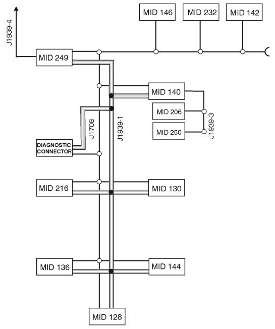
Data links |
|
|
|
|
|
|
|
|
|
W3005654 |
Note: Not all modules will be present |
MID 144 |
Vehicle ECU |
J1939–1 |
Main network SAE |
|
in every vehicle. |
|
MID 146 |
Climate control ECU |
|
J1939 |
|
|
MID 206 |
Radio |
J1939–3 |
Section of SAE J1939 |
MID 128 |
Engine ECU |
MID 216 |
Lighting Control |
|
under the instrument |
MID 136 |
Anti-lock Brake (ABS) |
|
Module |
|
cluster |
|
ECU |
MID 232 |
Airbag, control unit |
J1939–4 |
Section of SAE J1939 |
MID 140 |
Instrument Cluster |
MID 249 |
Body builder module |
|
under the bodybuilder |
MID 142 |
Satellite |
MID 250 |
Steering Wheel |
|
control unit |
|
Communications |
|
Module |
|
|
Volvo Trucks North America, Inc. |
Date |
Group |
No. |
Page |
Service Bulletin |
12.2004 |
371 |
44 |
6(25) |
SAE J1587/1708 |
|
|
|
|
For checking see “J1708 Information Link, Fault Tracing” page 14.
SAE J1587/1708 is used for, amongst other things, transmitting fault code information. Faults which can affect the entire SAE J1587/1708 datalink can create problems when fault tracing, since it can be difficult to communicate with the source in order to carry out tests using VCADS pro. A simple way of checking if VCADS pro is in contact with all control units on the SAE J1587/1708 link is “17034-2 Vehicle information, test”. An indication that there is a problem with SAE J1587/1708 can be that fault codes from a certain control unit can not be corrected.
There are various types of errors that store fault codes for the SAE J1587/1708 link (SID 250). If a control unit is able to store a fault code then the fault more than likely is associated with faulty wiring, connectors or sensors. The fault could be an open-circuit or short-circuit in the cable harness in one or more places. In order to determine an open-circuit in the cable harness, check the voltage levels at each control unit. See “J1708 Information Link, Fault Tracing” page 14.
Fault codes in the SAE J1587/1708 link (SID 250) can also be caused by another control unit not transmitting information. The reason for this can be due to faults in components connected to the other control unit. Therefore, all other fault codes must be corrected before starting the datalink fault tracing process.
List of MID numbers
Note: Not all MIDs will be present on every vehicle.
MID 128 |
Engine ECU |
MID 130 |
Transmission control unit |
MID 136 |
Anti-lock Brake (ABS) ECU |
MID 140 |
Instrument Cluster |
MID 142 |
Satellite Communications |
MID 144 |
Vehicle ECU |
MID 146 |
Climate control ECU |
MID 172 |
Test tool, ie. VCADS PRO |
MID 206 |
Radio |
MID 216 |
Lighting Control Module |
MID 219 |
VORAD/ACC |
MID 232 |
Airbag, control unit |
MID 249 |
Body builder module (BBM) |
MID 250 |
Steering Wheel Module |
Volvo Trucks North America, Inc. |
Date |
Group |
No. |
Page |
Service Bulletin |
12.2004 |
371 |
44 |
7(25) |
SAE J1939
For checking see “J1939 Control Link, Fault Tracing” page 16.
The information on the SAE J1939 control link is used for control functions. Therefore, the diagnostics for SAE J1939 have been developed and supplemented with more fault codes for a more precise reading. The fault codes that are transmitted on the SAE J1587/1708 link are also transmitted, in the event of more serious faults, on the SAE J1939 link.
If control unit A is missing the message from another control unit B, the fault codes PSID 200 - 214 are used to determine from which control unit the message is missing. If control unit B loses contact with the link, other control units can store fault codes indicating control unit B has lost communications.
Example:
If there is an open - circuit on the SAE J1939 link at the vehicle ECU (MID 144), PC connector, the message from the vehicle ECU does not reach the other control units on SAE J1939. The instrument cluster and ABS ECU use the messages from the vehicle ECU. The instrument cluster and ABS ECU store fault codes when the message is not received. The instrument cluster stores fault codes “MID 140 PSID 201 FMI 9” and the ABS ECU stores “MID 136 PSID 201 FMI 9”.
PSID 201 is stored by both the instrument cluster and ABS ECU which indicates that the vehicle control has an interruption in the SAE J-1939 data link. This can be useful in order to find faults on the data link. If there is a fault in the cable harness the fact that there is still contact between certain control units can be used to eliminate sections
of the cable harness. In the event of certain errors in the SAE J1939 link the fault codes are stored as a SID 231 message.
Note: It is important to remember which control units the vehicle is equipped with and which fault codes are stored in each control unit.
Explanation of PSID 200-214
Note: Not all control units will be present on every vehicle.
PSID 200 Open-circuit, bad data, data link, engine control unit (MID 128)
PSID 201 Open-circuit, bad data, data link, vehicle ECU (MID 144)
PSID 202 Open-circuit, data link, instrument cluster (MID 140)
PSID 204 Open-circuit, data link, ABS ECU (MID 136)
PSID 210 Open-circuit, data link, Lighting Control Module(LCM) (MID 216)
PSID 214 Open-circuit, data link, body builder module (MID 249)
Volvo Trucks North America, Inc. |
Date |
Group |
No. |
Page |
Service Bulletin |
12.2004 |
371 |
44 |
8(25) |
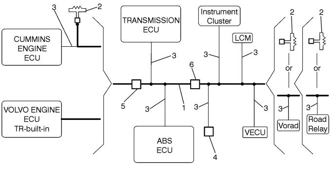
Data Link Construction |
|
|
|
|
1 |
Data link backbone |
|
W3005333 |
5 |
Chassis harness — engine harness in-line connector |
||
2 |
Terminating resistors |
6 |
Chassis harness — cab harness bulkhead pass-through |
3 |
Stub connections for ECUs |
|
connector |
4 |
Diagnostic connector |
|
|
The J1939 Control Data Link consists of a backbone (1), terminating resistors (2) at each end, and stubs spliced out (3) for each ECU on the data link. On vehicles with Volvo engines, the terminating resistor at the engine end is located inside the Engine ECU.
The J1939 Control Data Link complies with SAE standards and consists of 2 twisted wires:
•Wire 406 is yellow in color and carries the Controller Area Network high (CAN_H) digital signal of approximately 2–5 volts.
•Wire 407 is green in color and carries the Controller Area Network low (CAN_L) digital signal of approximately 0–3 volts.
 Loading...