


TSI
Number 030-500
Vehicle Management System
Vectro II From 1998
PV776-TSP144528
Foreword
The descriptions and service procedures contained in this manual are based on designs and methods studies carried out up to June 2001.
The products are under continuous development. Vehicles and components produced after the above date may therefore have different specifications and repair methods. When this is believed to have a significant bearing on this manual, supplementary service bulletins will be issued to cover the changes.
The new edition of this manual will update the changes.
In service procedures where the title incorporates an operation number, this is a reference to an S.R.T. (Standard Repair Time).
Service procedures which do not include an operation number in the title are for general information and no reference is made to an S.R.T.
The following levels of observations, cautions and warnings are used in this Service Documentation:
Note: Indicates a procedure, practice, or condition that must be followed in order to have the vehicle or component function in the manner intended.
Caution: Indicates an unsafe practice where damage to the product could occur.
Warning: Indicates an unsafe practice where personal injury or severe damage to the product could occur.
Danger: Indicates an unsafe practice where serious personal injury or death could occur.
Volvo Trucks North America, Inc.
Greensboro, NC USA
Order number: PV776-144528
© 2001 Volvo Trucks North America, Inc., Greensboro, NC USA
All rights reserved. No part of this publication may be reproduced, stored in retrieval system, or transmitted in any forms by any means, electronic, mechanical, photocopying, recording or otherwise, without the prior written permission of Volvo Trucks North America, Inc.
Contents |
|
General .................................................................................................... |
7 |
Vehicle Management System ................................................................ |
7 |
Engine Control System Glossary ........................................................ |
8 |
Specifications ....................................................................................... |
10 |
Description of Signals .......................................................................... |
10 |
EECU (D7C) and Breakout Box Connected in Series Between |
|
EECU and Wiring Harness ............................................................... |
10 |
EECU, D7C, with Breakout Box Connected to Wiring Harness Only |
13 |
EECU (D12B and D12C), Breakout Box Connected in Series Be- |
|
tween EECU and Wiring Harness ..................................................... |
16 |
EECU (D12B and D12C), Breakout Box Connected to Wiring |
|
Harness Only ..................................................................................... |
19 |
Pinouts ................................................................................................. |
22 |
Engine Electronic Control Unit (EECU) ............................................ |
22 |
Pinouts ................................................................................................. |
26 |
Vehicle Electronic Control Unit(VECU) ............................................. |
26 |
Schematic ............................................................................................ |
28 |
D12B .................................................................................................. |
28 |
Schematic ............................................................................................ |
29 |
D12C ................................................................................................. |
29 |
Schematic ............................................................................................ |
30 |
D7C ................................................................................................... |
30 |
Schematic ............................................................................................ |
31 |
VECU ................................................................................................. |
31 |
Tools ...................................................................................................... |
33 |
Special Tools ....................................................................................... |
33 |
Other Special Equipment .................................................................... |
35 |
Design and Function ........................................................................... |
37 |
Vehicle Management System .............................................................. |
37 |
Strategy ............................................................................................. |
37 |
Conventional Control Systems .......................................................... |
37 |
Data Link System .............................................................................. |
38 |
Data Links, Design and Function ...................................................... |
39 |
Diagnostic Connector ........................................................................ |
47 |
Communication Equipment ............................................................... |
48 |
Instrument Cluster ............................................................................. |
49 |
Vehicle Electronic Control Unit (VECU) ............................................ |
50 |
Engine Electronic Control Unit .......................................................... |
51 |
ABS Brake System ECU ................................................................... |
63 |
SRS Airbag ECU ............................................................................... |
64 |
Transmission ECU ............................................................................. |
65 |
Breakout Boxes and Harnesses ........................................................ |
66 |
VECU Overview ................................................................................ |
67 |
VECU Functions ................................................................................ |
68 |
Sensor Locations ............................................................................... |
73 |
Control Unit Locations ....................................................................... |
77 |
Fuses and Relays .............................................................................. |
81 |
Troubleshooting ................................................................................... |
85 |
Fault Code Troubleshooting ................................................................... |
85 |
Message and Parameter Descriptions ................................................ |
85 |
FMI Table ............................................................................................. |
87 |
Reading/Clearing Fault Codes .......................................................... |
88 |
1
Fault Tracing Strategy ....................................................................... |
88 |
MID 128 EECU ...................................................................................... |
92 |
MID 128 Fault Code Table .................................................................. |
92 |
MID 128 PID 45 Preheater Status ...................................................... |
96 |
Fault Codes ....................................................................................... |
96 |
MID 128 PID 45 Preheater Status, Check .......................................... |
97 |
MID 128 PID 49 ABS Control Status .................................................. |
98 |
Fault Codes ....................................................................................... |
98 |
MID 128 PID 49 ABS Control Status, Check ...................................... |
99 |
MID 128 PID 84 Road Speed ........................................................... |
100 |
Fault Codes ..................................................................................... |
100 |
MID 128 PID 84 Road Speed, Check ............................................... |
101 |
MID 128 PID 85 Cruise Control Status ............................................. |
102 |
Fault Codes ..................................................................................... |
102 |
MID 128 PID 85 Cruise Control Status, Check ................................ |
103 |
MID 128 PID 91 Accelerator Pedal Position ..................................... |
104 |
Fault Codes ..................................................................................... |
104 |
MID 128 PID 91 Accelerator Pedal Position, Check ......................... |
105 |
MID 128 PID 94 Fuel Delivery Pressure ........................................... |
106 |
D7C and D12C ................................................................................ |
106 |
Fault Codes ..................................................................................... |
106 |
MID 128 PID 94 Fuel Delivery Pressure, Check .............................. |
107 |
D7C and D12C ................................................................................ |
107 |
MID 128 PID 100 Engine Oil Pressure ............................................. |
110 |
Fault Codes ..................................................................................... |
110 |
MID 128 PID 100 Engine Oil Pressure, Check ................................. |
111 |
MID 128 PID 102 Boost Pressure ..................................................... |
114 |
Fault Codes ..................................................................................... |
114 |
MID 128 PID 102 Boost Pressure, Check ........................................ |
115 |
MID 128 PID 105 Boost Air Temperature ......................................... |
118 |
Fault Codes ..................................................................................... |
118 |
MID 128 PID 105 Boost Air Temperature, Check ............................. |
119 |
MID 128 PID 107 Air Filter Differential Pressure .............................. |
122 |
Fault Codes ..................................................................................... |
122 |
MID 128 PID 107 Air Filter Differential Pressure, Check .................. |
124 |
MID 128 PID 108 Atmospheric Pressure .......................................... |
125 |
Fault Codes ..................................................................................... |
125 |
MID 128 PID 110 Engine Coolant Temperature ............................... |
126 |
Fault Codes ..................................................................................... |
126 |
MID 128 PID 110 Engine Coolant Temperature, Check ................... |
127 |
MID 128 PID 111 Coolant Level ....................................................... |
129 |
Fault Codes ..................................................................................... |
129 |
MID 128 PID 111 Coolant Level, Check ........................................... |
130 |
MID 128 PID 158 Battery Voltage ..................................................... |
131 |
Fault Codes ..................................................................................... |
131 |
MID 128 PID 158 Battery Voltage, Check ........................................ |
132 |
MID 128 PID 172 Air Inlet Temperature ............................................ |
133 |
Fault Codes ..................................................................................... |
133 |
MID 128 PID 172 Air Inlet Temperature, Check ............................... |
134 |
MID 128 PID 174 Fuel Temperature ................................................. |
136 |
D7C and D12C ................................................................................ |
136 |
Fault Codes ..................................................................................... |
136 |
MID 128 PID 174 Fuel Temperature, Check ..................................... |
137 |
D7C and D12C ................................................................................ |
137 |
MID 128 PID 175 Engine Oil Temperature ....................................... |
140 |
2
Fault Codes ..................................................................................... |
140 |
MID 128 PID 175 Engine Oil Temperature, Check ........................... |
141 |
MID 128 PID 228 Road Speed Sensor Calibration .......................... |
144 |
Fault Codes ..................................................................................... |
144 |
MID 128 PID 228 Road Speed Sensor Calibration, Check .............. |
145 |
MID 128 PPID 86 Engine Brake Torque Percent .............................. |
146 |
Fault Codes ..................................................................................... |
146 |
MID 128 PPID 86 Engine Brake Torque Percent, Check ................. |
147 |
MID 128 PPID 119 High Coolant Temperature ................................. |
148 |
Fault Codes ..................................................................................... |
148 |
MID 128 PPID 119 High Coolant Temperature, Check .................... |
149 |
MID 128 PPID 122 VCB Engine Compression Brake ...................... |
151 |
D12B and D12C .............................................................................. |
151 |
Fault Codes ..................................................................................... |
151 |
MID 128 PPID 122 VCB Engine Compression Brake, Check .......... |
152 |
D12B and D12C .............................................................................. |
152 |
MID 128 PPID 123 EPG 2 ................................................................ |
153 |
D12B and D12C .............................................................................. |
153 |
Fault Codes ..................................................................................... |
153 |
MID 128 PPID 123 EPG 2, Check .................................................... |
154 |
D12B and D12C .............................................................................. |
154 |
MID 128 PPID 124 EPG 1 ................................................................ |
155 |
Fault Codes ..................................................................................... |
155 |
MID 128 PPID 124 EPG 1, Check .................................................... |
156 |
MID 128 SID 1/2/3/4/5/6 Injector ..................................................... |
157 |
D12B and D12C .............................................................................. |
157 |
Fault Codes ..................................................................................... |
157 |
MID 128 SID 1/2/3/4/5/6 Injector, Check .......................................... |
159 |
D12B and D12C .............................................................................. |
159 |
MID 128 SID 17 Fuel Shutoff Valve .................................................. |
161 |
Fault Codes ..................................................................................... |
161 |
MID 128 SID 17 Fuel Shutoff Valve, Check ...................................... |
162 |
D7C only .......................................................................................... |
162 |
MID 128 SID 20 Timing Sleeve ......................................................... |
163 |
D7C only .......................................................................................... |
163 |
Fault Codes ..................................................................................... |
163 |
MID 128 SID 20 Timing Sleeve, Check ............................................ |
165 |
D7C only .......................................................................................... |
165 |
MID 128 SID 21 Engine Position Timing Sensor .............................. |
166 |
D12B and D12C .............................................................................. |
166 |
Fault Codes ..................................................................................... |
166 |
MID 128 SID 21 Engine Position Timing Sensor, Check .................. |
167 |
D12B and D12C .............................................................................. |
167 |
MID 128 SID 21 Needle Lift Sensor ................................................. |
168 |
Fault Codes ..................................................................................... |
168 |
MID 128 SID 21 Needle Lift Sensor, Check ..................................... |
169 |
D7C only .......................................................................................... |
169 |
MID 128 SID 22 Engine Speed Sensor ............................................ |
170 |
Fault Codes ..................................................................................... |
170 |
MID 128 SID 22 Engine Speed Sensor, Check ................................ |
171 |
MID 128 SID 23 Rack Actuator ......................................................... |
172 |
D7C only .......................................................................................... |
172 |
Fault Codes ..................................................................................... |
172 |
MID 128 SID 23 Rack Actuator, Check ............................................. |
174 |
D7C only .......................................................................................... |
174 |
3
MID 128 SID 24 Rack Position Sensor ............................................. |
175 |
D7C only .......................................................................................... |
175 |
Fault Codes ..................................................................................... |
175 |
MID 128 SID 24 Rack Position Sensor, Check ................................. |
176 |
D7C only .......................................................................................... |
176 |
MID 128 SID 33 Fan Control ............................................................. |
177 |
Fault Codes ..................................................................................... |
177 |
MID 128 SID 33 Fan Control, Check ................................................ |
178 |
MID 128 SID 64 Redundant Engine Speed Sensor ......................... |
179 |
D7C only .......................................................................................... |
179 |
Fault Codes ..................................................................................... |
179 |
MID 128 SID 64 Redundant Engine Speed Sensor, Check ............. |
180 |
D7C only .......................................................................................... |
180 |
MID 128 SID 70 Preheater Element 1 .............................................. |
181 |
Fault Codes ..................................................................................... |
181 |
MID 128 SID 70 Preheater Element 1, Check .................................. |
182 |
MID 128 SID 71 Preheater Element 2 .............................................. |
183 |
D12B only ........................................................................................ |
183 |
Fault Codes ..................................................................................... |
183 |
MID 128 SID 71 Preheater Element 2, Check .................................. |
184 |
D12B ................................................................................................ |
184 |
MID 128 SID 230 Idle Validation Switch 1 ........................................ |
185 |
Fault Codes ..................................................................................... |
185 |
MID 128 SID 230 Idle Validation Switch 1, Check ............................ |
186 |
MID 128 SID 231 SAE J1939 Control Link ....................................... |
187 |
Fault Codes ..................................................................................... |
187 |
MID 128 SID 232 5 Volt DC Supply .................................................. |
189 |
Fault Codes ..................................................................................... |
189 |
MID 128 SID 232 5 Volt DC Supply, Check ...................................... |
190 |
MID 128 SID 240 Program Memory ................................................. |
191 |
Fault Codes ..................................................................................... |
191 |
MID 128 SID 250 SAE J1587/1708 Information Link ....................... |
192 |
Fault Codes ..................................................................................... |
192 |
MID 128 SID 253 Data Set Memory EEPROM ................................ |
193 |
Fault Codes ..................................................................................... |
193 |
MID 128 SID 254 Engine Electronic Control Unit (EECU) ............... |
194 |
Fault Codes ..................................................................................... |
194 |
MID 144 VECU .................................................................................... |
196 |
MID 144 Fault Code Table ................................................................ |
196 |
MID 144 PID 29 Second Accelerator Pedal Position Sensor ........... |
198 |
Fault Codes ..................................................................................... |
198 |
MID 144 PID 29 Second Accelerator Pedal Position Sensor, Check |
199 |
MID 144 PID 84 Road Speed ........................................................... |
201 |
Fault Codes ..................................................................................... |
201 |
MID 144 PID 84 Road Speed, Check ............................................... |
202 |
MID 144 PID 91 Accelerator Pedal Position ..................................... |
204 |
Fault Codes ..................................................................................... |
204 |
MID 144 PID 91 Accelerator Pedal Position, Check ......................... |
205 |
MID 144 PID 152 VECU, Number of Resets .................................... |
207 |
Fault Codes ..................................................................................... |
207 |
MID 144 PPID 69 Idle Validation Switch ........................................... |
208 |
Fault Codes ..................................................................................... |
208 |
MID 144 PPID 69 Idle Validation Switch, Check .............................. |
209 |
MID 144 PPID 70 Pedal Switches, Supply ....................................... |
211 |
Fault Codes ..................................................................................... |
211 |
4
MID 144 PPID |
70 Pedal Switches, Supply, Check ........................... |
212 |
MID 144 PPID 71 Cruise Control and Engine Brake, Supply Switch |
215 |
|
Fault Codes |
..................................................................................... |
215 |
MID 144 PPID |
71 Cruise Control and Engine Brake, Supply |
|
Switch, Check |
.................................................................................... |
216 |
MID 144 PPID ..................... |
72 Accelerator Pedal, Supply Sensors |
220 |
Fault Codess ................................................................................... |
|
220 |
MID 144 PPID ......... |
72 Accelerator Pedal, Supply Sensors, Check |
221 |
MID 144 PPID ........ |
73 Second Accelerator Pedal, Supply Sensors |
223 |
Fault Codes ..................................................................................... |
|
223 |
MID 144 PPID |
73 Second Accelerator Pedal, Supply Sensors, |
|
Check ................................................................................................. |
|
224 |
MID 144 PPID ............... |
75 Range Inhibitor, Solenoid Valve Status |
226 |
Fault Codes ..................................................................................... |
|
226 |
MID 144 PPID |
75 Range Inhibitor, Solenoid Valve Status, Check ... 227 |
|
MID 144 SID 230 ........................................Idle Validation Switch 1 |
229 |
|
Fault Codes ..................................................................................... |
|
229 |
MID 144 SID 230 ............................Idle Validation Switch 1, Check |
230 |
|
MID 144 SID 231 .......................................SAE J1939 Control Link |
232 |
|
Fault Codes ..................................................................................... |
|
232 |
MID 144 SID 231 ..........................SAE J1939 Control Link, Check |
233 |
|
MID 144 SID 240 .................................................Program Memory |
234 |
|
Fault Codes ..................................................................................... |
|
234 |
MID 144 SID 243 ....................................Cruise Control Set Switch |
235 |
|
Fault Codes ..................................................................................... |
|
235 |
MID 144 SID 243 .......................Cruise Control Set Switch, Check |
236 |
|
MID 144 SID 250 .......................SAE J1587/1708 Information Link |
238 |
|
Fault Codes ..................................................................................... |
|
238 |
MID 144 SID 250 ...........SAE J1587/1708 Information Link, Check |
239 |
|
MID 144 SID 253 ................................Data Set Memory EEPROM |
240 |
|
Fault Codes ..................................................................................... |
|
240 |
MID 144 PSID ......................................... |
3 Idle Validation Switch 3 |
241 |
Fault Codes ..................................................................................... |
|
241 |
MID 144 PSID ............................. |
3 Idle Validation Switch 3, Check |
242 |
Service Procedures ........................................................................... |
245 |
|
Engine ECU, Replacement ................................................................ |
245 |
|
Feedback |
|
|
Operation Numbers |
|
|
5
6
Group 28 |
General |
General
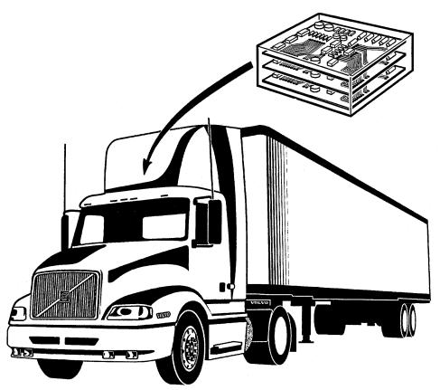
Vehicle Management System
W2002520
This information covers the Vehicle Management System, which includes VECTRO II electronics, the vehicle ECU, and other control systems used in the vehicle.
7
Group 28 |
General |
Engine Control System Glossary
ATA
American Trucking Association
ATDC (After Top Dead Center)
The 180 of crankshaft rotation after the piston reaches top center (normal direction of rotation).
AC (Alternating Current)
An electrical current that alternates level and direction.
BTDC (Before Top Dead Center)
The 180 of crankshaft rotation before the piston reaches top center (normal direction of rotation).
INFO lamp
Light that warns the operator of an active diagnostic fault code; also referred to as the diagnostic lamp.
Data link
An electrical connection for communication with other microprocessor-based devices (such as powertrain control, trip recorders and maintenance systems) that are compatible with the ATA and SAE standard.
Diagnostic fault code
These codes indicate an electronic system malfunction, indicating a problem with the D12 electrical systems.
Diagnostic flash code
Codes flashed out in a series via the INFO lamp to indicate an active fault code.
DC (Direct Current)
An electrical current that flows in one direction only.
EEPROM (Electrical Erasable Programmable Read
Only Memory)
The contents of this type of memory may be electronically erased and new information programmed into the device.
EECU (Engine Electronic Control Unit)
The computer that controls the power supplied to the engine electronics, monitors and governs engine functions.
EUI (Electronic Unit Injector)
An injector pump which is mechanically activated and electronically controlled. It combines metering and injecting in a single unit.
Engine brake disable system
During the time ABS (anti-lock braking system) is active, the engine brake is disabled.
FMI (Failure Mode Identifier)
Numbers and names used to identify how a system or part failed.
FMI |
Description |
|
|
0 |
Data valid but above normal operating range |
|
|
1 |
Data valid but below normal operating range |
|
|
|
|
2 |
Data erratic, intermittent, or incorrect |
|
|
|
|
3 |
Voltage above normal |
|
|
|
|
4 |
Voltage below normal |
|
|
|
|
5 |
Current below normal or open circuit |
|
|
|
|
6 |
Current above normal or short circuit |
|
|
|
|
7 |
Mechanical system not responding properly |
|
|
|
|
8 |
Abnormal frequency, pulse rate or period |
|
|
|
|
9 |
Abnormal update |
|
|
|
|
10 |
Abnormal rate of change |
|
|
|
|
11 |
Failure mode not identifiable |
|
|
|
|
12 |
Defective device or component |
|
|
13 |
Uncalibrated device or component |
|
|
|
|
14/15 |
Reserved for future assignment |
|
|
|
|
Hz (Hertz)
Measure of frequency in cycles per second.
MID
Message Identification Description
Open circuit
Condition where an electrical wire or connector is broken, preventing signal or supply voltage from reaching its intended destination.
Parameter
A programmable value that affects the characteristics or behavior of the engine and/or vehicle.
8
Group 28 |
General |
PID
Parameter Identification code.
PTO (Power Takeoff)
Operated with the cruise control switches, this mode permits setting a constant engine rpm when the vehicle is not moving.
PWM (Pulse Width Modulation)
A signal consisting of variable-width pulses at fixed intervals to vary; “TIME ON” versus versus “TIME OFF.”
RAM (Random Access Memory)
A memory that has stored information immediately available when addressed.
Reference voltage
A regulated voltage supplied by the EECU to a sensor, which uses it to generate a signal voltage.
Password
A group of seven alphanumeric characters designed to restrict access to level-2 parameters. The password is automatically defaulted to seven empty spaces if customer has not specified password.
SAE
Society of Automotive Engineers.
Short circuit
A connection of comparatively low resistance, accidentally or intentionally made between two points on a circuit.
SID
Subsystem Identification code.
Signal
A voltage value used to transmit information typically from a sensor to the EECU.
Supply voltage
A constant voltage that supplies electrical power to a component. It may be generated by the EECU or supplied by the vehicle battery.
Throttle Position Sensor (TPS)
An electronic sensor that is connected to the accelerator pedal and sends a Pulse Width Modulated signal to the EECU.
Vehicle Specification Programming (VSP)
VSP consists of two levels of programming: engine configuration (level 1) and customer parameters (level 2).
Vehicle Speed Sensor (VSS)
An electromagnetic device that measures vehicle speed from the rotation of gear teeth in the drivetrain of the vehicle.
VEB (Volvo Engine Brake)
Consists of a compression brake (VCB) and an exhaust pressure governor (EPG).
9
Group 28 |
Specifications |
Specifications
Description of Signals
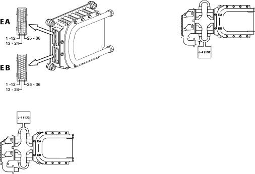
EECU (D7C) and Breakout Box Connected in Series Between EECU and Wiring Harness
For the measurements below, the following applies:
•Breakout box J-41132 connected between connector EA or EB and the EECU.
•Jumper harness J–43233 connected between connector EA or EB and the EECU.
•The EECU connected.
•Ignition key in ON position.
•Engine not running.
•Measuring voltage.
W2002710
Fig. 3: EECU voltage check, EB
W2003555
Fig. 1: EECU with pinouts
W2002712
Fig. 2: EECU voltage check, EA
B+ = battery voltage
Connec- |
Signal type |
Measuring points |
Ignition key in the ON position |
Other |
|
tion |
|
|
|
|
|
|
|
|
|
|
|
EA1 |
Oil temperature sensor, signal |
EA1 - EA5 |
3.0 |
V (+20 C/68 F) |
|
|
|
|
0.4 |
V (+100 C/212 F) |
|
|
|
|
|
|
|
EA2 |
Intake manifold temperature sensor, |
EA2 - EA5 |
2.6 |
V (+20 C/68 F) |
|
|
signal |
|
1.6 |
V (+40 C/104 F) |
|
|
|
|
|
|
|
EA3 |
Intake manifold pressure sensor, sig- |
EA3 - EA5 |
1.1 |
V (sea level) |
|
|
nal |
|
|
|
|
|
|
|
|
|
|
EA4 |
Supply to sensors (5 V), + |
EA4 - EA5 |
4.8 |
- 5.15 V |
|
|
|
|
|
|
|
EA5 |
Signal ground to sensors, - |
|
|
|
|
|
|
|
|
|
|
EA6 |
Not currently used |
|
|
|
|
|
|
|
|
|
|
EA7 |
Redundant engine speed sensor, + |
|
|
|
|
|
|
|
|
|
|
EA8 |
Rack drive PWM, + |
|
|
|
|
|
|
|
|
|
|
EA9 |
Timing sleeve PWM, + |
|
|
|
|
|
|
|
|
|
|
10
Group 28 |
|
|
|
Specifications |
|
|
|
|
|
Connec- |
Signal type |
Measuring points |
Ignition key in the ON position |
Other |
tion |
|
|
|
|
|
|
|
|
|
EA10 |
Rack drive PWM, - |
|
|
|
|
|
|
|
|
EA11 |
Not currently used |
|
|
|
|
|
|
|
|
EA12 |
Not currently used |
|
|
|
|
|
|
|
|
EA13 |
Fuel temperature sensor, signal |
EA13 - EA5 |
3.0 V (+20 C/68 F) |
|
|
|
|
2.0 V (+40 C/104 F) |
|
|
|
|
|
|
EA14 |
Oil pressure sensor, signal |
EA14 - EA5 |
0.5 V (for cold engines) |
|
|
|
|
|
|
EA15 |
Needle lift sensor, + |
|
|
|
|
|
|
|
|
EA16 |
Rack position sensor, search coil |
|
|
|
|
|
|
|
|
EA17 |
Rack position sensor, common |
|
|
|
|
|
|
|
|
EA18 |
Redundant engine speed sensor, - |
|
|
|
|
|
|
|
|
EA19 |
Not currently used |
|
|
|
|
|
|
|
|
EA20 |
Not currently used |
|
|
|
|
|
|
|
|
EA21 |
Timing sleeve PWM, - |
|
|
|
|
|
|
|
|
EA22 |
Not currently used |
|
|
|
|
|
|
|
|
EA23 |
Not currently used |
|
|
|
|
|
|
|
|
EA24 |
Not currently used |
|
|
|
|
|
|
|
|
EA25 |
Coolant temperature sensor, signal |
EA25 - EA5 |
3.0 V (+20 C/68 F) |
|
|
|
|
0.6 V (+85 C/185 F) |
|
|
|
|
|
|
EA26 |
Not currently used |
|
|
|
|
|
|
|
|
EA27 |
Fuel pressure sensor, signal |
EA27-EA5 |
≈ 0.5V (for cold engines) |
D12 C |
|
|
|
|
|
EA28 |
Needle lift sensor, - |
|
|
|
|
|
|
|
|
EA29 |
Rack position sensor, reference coil |
|
|
|
|
|
|
|
|
EA30 |
Engine speed sensor (crank), + |
|
|
|
|
|
|
|
|
EA31 |
Engine speed sensor (crank), - |
|
|
|
|
|
|
|
|
EA32 |
Not currently used |
|
|
|
|
|
|
|
|
EA33 |
Not currently used |
|
|
|
|
|
|
|
|
EA34 |
Not currently used |
|
|
|
|
|
|
|
|
EA35 |
Not currently used |
|
|
|
|
|
|
|
|
EA36 |
Not currently used |
|
|
|
|
|
|
|
|
EB1 |
SAE J1939 A Communications link |
EB1/EB9 |
≈2-5V |
|
|
|
|
|
|
EB2 |
SAE J1939 B Communications link |
EB2/EB9 |
≈0-3V |
|
|
|
|
|
|
EB3 |
Ambient air temperature sensor, sig- |
EB3 - EB13 |
2.6 V (+20 C/68 F) |
|
|
nal |
|
1.2 V (+50 C/122 F) |
|
|
|
|
|
|
EB4 |
Buffered idle validation switch |
EB4 - EB9 |
< 4 V (idle) |
|
|
|
|
> 8 V (off idle) |
|
|
|
|
|
|
EB5 |
Pre-heat sense 1 |
EB5 - EB9 |
55 % of B+ (open) |
Normally closed with |
|
|
|
0 V (closed) |
the ignition key in the |
|
|
|
|
ON position. |
|
|
|
|
|
EB6 |
Not currently used |
|
|
|
|
|
|
|
|
11
Group 28 |
|
|
|
Specifications |
|
|
|
|
|
Connec- |
Signal type |
Measuring points |
Ignition key in the ON position |
Other |
tion |
|
|
|
|
|
|
|
|
|
EB7 |
Coolant level sensor, signal |
EB7 - EB8 |
80% B+ (open) |
Applies to WX and |
|
|
|
0 V (closed) |
VN. Normally open |
|
|
|
|
with the ignition key in |
|
|
|
|
the ON position. |
|
|
|
|
|
EB8 |
Signal ground to sensors, - |
|
|
|
|
|
|
|
|
EB9 |
EECU ground, - |
|
|
|
|
|
|
|
|
EB10 |
EECU ground, - |
|
|
|
|
|
|
|
|
EB11 |
EECU B+ |
EB11 - EB9 |
B+ |
|
|
|
|
|
|
EB12 |
EECU B+ |
EB12 - EB10 |
B+ |
|
|
|
|
|
|
EB13 |
Ambient air temperature sensor |
|
|
|
|
|
|
|
|
EB14 |
Not currently used |
|
|
|
|
|
|
|
|
EB15 |
Not currently used |
|
|
|
|
|
|
|
|
EB16 |
Not currently used |
|
|
|
|
|
|
|
|
EB17 |
Air filter indicator sensor signal |
|
|
|
|
|
|
|
|
EB18 |
Not currently used |
|
|
|
|
|
|
|
|
EB19 |
Not currently used |
|
|
|
|
|
|
|
|
EB20 |
Not currently used |
|
|
|
|
|
|
|
|
EB21 |
Fan control (if equipped with on/off |
EB21 - EB9 |
B+ (fan on) |
Normally ON with the |
|
fan) |
|
0 V (fan off) |
ignition key in the ON |
|
|
|
|
position. |
|
|
|
|
|
EB22 |
Not currently used |
|
|
|
|
|
|
|
|
EB23 |
Not currently used |
|
|
|
|
|
|
|
|
EB24 |
EOL Enable |
EB24 - EB9 |
< 6 V or O/C (EOL Disable) |
|
|
|
|
> 9.6 V (EOL Enable) |
|
|
|
|
|
|
EB25 |
SAE J1587A/J1708A Information link |
EB25-EB9 |
≈ 0-5V |
|
|
|
|
|
|
EB26 |
SAE J1587B/J1708B Information link |
EB26-EB9 |
≈ 0-5V |
|
|
|
|
|
|
EB27 |
Not currently used |
|
|
|
|
|
|
|
|
EB28 |
Not currently used |
|
|
|
|
|
|
|
|
EB29 |
Not currently used |
|
|
|
|
|
|
|
|
EB30 |
Not currently used |
|
|
|
|
|
|
|
|
EB31 |
Pre-heating relay, Coil ground |
EB31 - EB9 |
B+ (pre-heat off) |
Normally ON with the |
|
|
|
0 V (pre-heat on) |
ignition key in the ON |
|
|
|
|
position. |
|
|
|
|
|
EB32 |
Not currently used |
|
|
|
|
|
|
|
|
EB33 |
Not currently used |
|
|
|
|
|
|
|
|
EB34 |
Fuel shut-off valve |
EB34 - EB9 |
0 V (valve on) |
Normally ON with the |
|
|
|
> 1.0V (valve off) |
ignition key in the ON |
|
|
|
|
position. |
|
|
|
|
|
EB35 |
EPG 1 |
EB35 - EB9 |
B+ (EPG off) |
Normally OFF with |
|
|
|
0 V (EPG on) |
the ignition key in the |
|
|
|
|
ON position. |
|
|
|
|
|
EB36 |
Not currently used |
|
|
|
|
|
|
|
|
12
Group 28 |
Specifications |
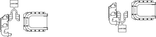
EECU, D7C, with Breakout Box Connected to Wiring Harness Only
For the measurements below, the following applies:
•Breakout box J-41132 connected to connector EA or EB.
•The EECU is not connected.
•Ignition key must be in the OFF position.
•Measuring resistance.
W2002713
|
W2002711 |
|
Fig. 5: EECU harness checks, EB |
|
|
Fig. 4: EECU harness checks, EA |
|
|
|
|
|
|
|
|
|
|
|
Connec- |
Signal type |
Measuring points |
|
Ignition key in the OFF position |
Other |
tion |
|
|
|
|
|
|
|
|
|
|
|
EA1 |
Oil temperature sensor, signal |
EA1 / EA5 |
|
1.9 k (+20 C/68 F) |
|
|
|
|
|
100 (+100 C/212 F) |
|
|
|
|
|
|
|
EA2 |
Intake manifold temperature sensor, |
EA2 / EA5 |
|
6.2 k (+20 C/68 F) |
|
|
signal |
|
|
2.5 k (+40 C/104 F) |
|
|
|
|
|
|
|
EA3 |
Intake manifold pressure sensor, sig- |
|
|
|
|
nal |
|
|
|
|
|
|
|
|
|
|
|
EA4 |
Sensor supply to (5 V), + |
|
|
|
|
|
|
|
|
|
|
EA5 |
Sensors ground , - |
|
|
|
|
|
|
|
|
|
|
EA6 |
Not currently used |
|
|
|
|
|
|
|
|
|
|
EA7 |
Redundant engine speed sensor, + |
EA7 / EA18 |
|
775 - 945 |
|
|
|
|
|
|
|
EA8 |
Rack drive PWM, + |
EA8 / EA10 |
|
1.5 |
|
|
|
EA8 / alternate |
|
open circuit |
|
|
|
ground |
|
|
|
|
|
|
|
|
|
EA9 |
Timing sleeve PWM, + |
EA9 / EA21 |
|
1.5 |
|
|
|
EA9 / alternate |
|
open circuit |
|
|
|
ground |
|
|
|
|
|
|
|
|
|
EA10 |
Rack drive PWM, - |
EA10 / alternate |
|
open circuit (see also EA8) |
|
|
|
ground |
|
|
|
|
|
|
|
|
|
EA11 |
Not currently used |
|
|
|
|
|
|
|
|
|
|
EA12 |
Not currently used |
|
|
|
|
|
|
|
|
|
|
EA13 |
Fuel temperature sensor, signal |
EA13 / EA5 |
|
1.9 k (+20 C/68 F) |
|
|
|
|
|
800 (+40 C/104 F) |
|
|
|
|
|
|
|
EA14 |
Oil pressure sensor, signal |
|
|
|
|
|
|
|
|
|
|
EA15 |
Needle lift sensor, + |
EA15 / EA28 |
|
65 - 165 |
|
|
|
|
|
|
|
EA16 |
Rack position sensor, search coil |
EA16 / EA17 |
|
20.0 |
|
|
|
|
|
|
|
EA17 |
Rack position sensor, common |
|
|
|
|
|
|
|
|
|
|
EA18 |
Redundant engine speed sensor, - |
EA18 / EA7 |
|
775 - 945 |
|
|
|
|
|
|
|
EA19 |
Not currently used |
|
|
|
|
|
|
|
|
|
|
13
Group 28 |
|
|
|
Specifications |
|
|
|
|
|
Connec- |
Signal type |
Measuring points |
Ignition key in the OFF position |
Other |
tion |
|
|
|
|
|
|
|
|
|
EA20 |
Not currently used |
|
|
|
|
|
|
|
|
EA21 |
Timing sleeve PWM, - |
EA21 / alternate |
open circuit (see also EA9) |
|
|
|
ground |
|
|
|
|
|
|
|
EA22 |
Not currently used |
|
|
|
|
|
|
|
|
EA23 |
Not currently used |
|
|
|
|
|
|
|
|
EA24 |
Not currently used |
|
|
|
|
|
|
|
|
EA25 |
Coolant temperature sensor, signal |
EA25 / EA5 |
1.9 k (+20 C/68 F) |
|
|
|
|
160 (+85 C/185 F) |
|
|
|
|
|
|
EA26 |
Not currently used |
|
|
|
|
|
|
|
|
EA27 |
Fuel pressure sensor |
|
|
D12 C |
|
|
|
|
|
EA28 |
Needle lift sensor, - |
|
|
|
|
|
|
|
|
EA29 |
Rack position sensor, reference coil |
EA29 / EA17 |
20.0 |
|
|
|
|
|
|
EA30 |
Engine speed sensor (crank), + |
EA30 / EA31 |
775 - 945 |
|
|
|
|
|
|
EA31 |
Engine speed sensor (crank), - |
EA31 / EA30 |
775 - 945 |
|
|
|
|
|
|
EA32 |
Not currently used |
|
|
|
|
|
|
|
|
EA33 |
Not currently used |
|
|
|
|
|
|
|
|
EA34 |
Not currently used |
|
|
|
|
|
|
|
|
EA35 |
Not currently used |
|
|
|
|
|
|
|
|
EA36 |
Not currently used |
|
|
|
|
|
|
|
|
EB1 |
SAE J1939A Communications link |
|
|
|
|
|
|
|
|
EB2 |
SAE J1939B Communications link |
|
|
|
|
|
|
|
|
EB3 |
Ambient air temperature sensor, sig- |
EB3 / EB13 |
6.2 k (+20 C/68 F) |
|
|
nal |
|
1.7 k (+50 C/122 F) |
|
|
|
|
|
|
EB4 |
Buffered idle validation switch |
|
|
|
|
|
|
|
|
EB5 |
Pre-heat sense 1 |
EB5 / EB9 |
open circuit (open) |
|
|
|
|
< 5 (closed) |
|
|
|
|
|
|
EB6 |
Not currently used |
|
|
|
|
|
|
|
|
EB7 |
Coolant level sensor, signal |
EB7 / EB8 |
open circuit (coolant level normal) |
Applies to WX and VN |
|
|
|
<1 (coolant level low) |
|
|
|
|
|
|
EB8 |
Sensor ground |
|
|
|
|
|
|
|
|
EB9 |
EECU ground, - |
|
|
|
|
|
|
|
|
EB10 |
EECU ground, - |
|
|
|
|
|
|
|
|
EB11 |
EECU, B+ |
|
|
|
|
|
|
|
|
EB12 |
EECU, B+ |
|
|
|
|
|
|
|
|
EB13 |
Ambient air temperature ground |
|
|
|
|
|
|
|
|
EB14 |
Not currently used |
|
|
|
|
|
|
|
|
EB15 |
Not currently used |
|
|
|
|
|
|
|
|
EB16 |
Not currently used |
|
|
|
|
|
|
|
|
EB17 |
Air filter indicator sensor signal |
|
|
|
|
|
|
|
|
EB18 |
Not currently used |
|
|
|
|
|
|
|
|
EB19 |
Not currently used |
|
|
|
|
|
|
|
|
EB20 |
Not currently used |
|
|
|
|
|
|
|
|
EB21 |
Not currently used |
|
|
|
|
|
|
|
|
EB22 |
Not currently used |
|
|
|
|
|
|
|
|
EB23 |
Not currently used |
|
|
|
|
|
|
|
|
EB24 |
EOL Enable |
EB24/EB9 |
open circuit (open) |
|
|
|
|
|
|
14
Group 28 |
|
|
|
Specifications |
|
|
|
|
|
Connec- |
Signal type |
Measuring points |
Ignition key in the OFF position |
Other |
tion |
|
|
|
|
|
|
|
|
|
|
|
EB25 / (connection |
<1 |
|
|
|
A in 6 pin diagnos- |
|
|
EB25 |
SAE J1587/J1708 A Information link |
tics connector) |
|
|
|
|
|
||
EB25 / (connection |
<1 |
|
||
|
|
|
||
|
|
F in 9 pin diagnos- |
|
|
|
|
tics connector) |
|
|
|
|
|
|
|
EB26 |
SAE J1587/J1708 B Information link |
EB26 / (connection |
<1 |
|
|
|
B in the 6 pin diag- |
|
|
|
|
nostics connector) |
|
|
|
|
|
|
|
|
|
EB26 / (connection |
<1 |
|
|
|
G in the 9 pin diag- |
|
|
|
|
nostics connector) |
|
|
|
|
|
|
|
EB27 |
Not currently used |
|
|
|
|
|
|
|
|
EB28 |
Not currently used |
|
|
|
|
|
|
|
|
EB29 |
Not currently used |
|
|
|
|
|
|
|
|
EB30 |
Not currently used |
|
|
|
|
|
|
|
|
EB31 |
Pre-heating relay, coil ground |
|
|
|
|
|
|
|
|
EB32 |
Not currently used |
|
|
|
|
|
|
|
|
EB33 |
Not currently used |
|
|
|
|
|
|
|
|
EB34 |
Fuel shut-off valve, include |
|
|
|
|
|
|
|
|
EB35 |
EPG 1, - |
|
|
|
|
|
|
|
|
EB36 |
Not currently used |
|
|
|
|
|
|
|
|
15
Group 28 |
Specifications |
EECU (D12B and D12C), Breakout Box Connected in Series Between EECU and Wiring Harness
For the measurements below, the following applies:
•Breakout box J-41132 connected between connector EA or EB and the EECU.
•Jumper harness J43233 connected between connector EA or EB and the EECU.
•
•
•
•
The EECU connected.
Ignition key in ON position.
Engine not running.
Measuring voltage.
W2002710
W2002712
Fig. 6: EECU voltage check, EA
Fig. 7: EECU voltage check, EB
B+ = battery voltage
Connec- |
Signal type |
Measuring points |
Ignition key in the ON position |
Other |
|
tion |
|
|
|
|
|
|
|
|
|
|
|
EA1 |
Oil temperature sensor, signal |
EA1 / EA5 |
3.0 |
V (+20 C/68 F) |
|
|
|
|
0.4 |
V (+100 C/212 F) |
|
|
|
|
|
|
|
EA2 |
Intake manifold temperature sensor, |
EA2 / EA5 |
2.6 |
V (+20 C/68 F) |
|
|
signal |
|
1.6 |
V (+40 C/104 F) |
|
|
|
|
|
|
|
EA3 |
Intake manifold pressure sensor, sig- |
EA3 / EA5 |
1.1 |
V (sea level) |
|
|
nal |
|
|
|
|
|
|
|
|
|
|
EA4 |
Sensor supply (5 V), + |
EA4 / EA5 |
4.8 |
- 5.15 V |
|
|
|
|
|
|
|
EA5 |
Sensor ground |
|
|
|
|
|
|
|
|
|
|
EA6 |
Not currently used |
|
|
|
|
|
|
|
|
|
|
EA7 |
Engine position sensor (cam), + |
|
|
|
|
|
|
|
|
|
|
EA8 |
Not currently used |
|
|
|
|
|
|
|
|
|
|
EA9 |
Not currently used |
|
|
|
|
|
|
|
|
|
|
EA10 |
Not currently used |
|
|
|
|
|
|
|
|
|
|
EA11 |
Unit injector cylinder 1, - |
|
|
|
|
|
|
|
|
|
|
EA12 |
Unit injector cylinder 1, 2, 3 (90 |
|
|
|
|
|
Volt), + |
|
|
|
|
|
|
|
|
|
|
EA13 |
Fuel temperature sensor, signal |
|
|
|
D12 C |
|
|
|
|
|
|
EA14 |
Oil pressure sensor, signal |
EA14 / EA5 |
0.5 |
V (for cold engines) |
|
|
|
|
|
|
|
EA15 |
Not currently used |
|
|
|
|
|
|
|
|
|
|
16
Group 28 |
|
|
|
Specifications |
|
|
|
|
|
Connec- |
Signal type |
Measuring points |
Ignition key in the ON position |
Other |
tion |
|
|
|
|
|
|
|
|
|
EA16 |
Not currently used |
|
|
|
|
|
|
|
|
EA17 |
Not currently used |
|
|
|
|
|
|
|
|
EA18 |
Engine position sensor (cam), - |
|
|
|
|
|
|
|
|
EA19 |
Not currently used |
|
|
|
|
|
|
|
|
EA20 |
Not currently used |
|
|
|
|
|
|
|
|
EA21 |
Not currently used |
|
|
|
|
|
|
|
|
EA22 |
Unit injector cylinder 2, - |
|
|
|
|
|
|
|
|
EA23 |
Unit injector cylinder 3, - |
|
|
|
|
|
|
|
|
EA24 |
Unit injector cylinder 4, 5, 6 (90 |
|
|
|
|
Volt), + |
|
|
|
|
|
|
|
|
EA25 |
Coolant temperature sensor, signal |
EA25 / EA5 |
3.0 V (+20 C/68 F) |
|
|
|
|
0.6 V (+85 C/185 F) |
|
|
|
|
|
|
EA26 |
Not currently used |
|
|
|
|
|
|
|
|
EA27 |
Fuel pressure sensor |
|
|
D12 C |
|
|
|
|
|
EA28 |
Not currently used |
|
|
|
|
|
|
|
|
EA29 |
Not currently used |
|
|
|
|
|
|
|
|
EA30 |
Engine speed sensor (crank), + |
|
|
|
|
|
|
|
|
EA31 |
Engine speed sensor (crank), - |
|
|
|
|
|
|
|
|
EA32 |
Not currently used |
|
|
|
|
|
|
|
|
EA33 |
VCB, - |
EA33 / alternate |
B+ (VCB off) |
Normally OFF with |
|
|
ground |
0 V (VCB on) |
the ignition key in the |
|
|
|
|
ON position. |
|
|
|
|
|
EA34 |
Unit injector cylinder 4, - |
|
|
|
|
|
|
|
|
EA35 |
Unit injector cylinder 5, - |
|
|
|
|
|
|
|
|
EA36 |
Unit injector cylinder 6, - |
|
|
|
|
|
|
|
|
EB1 |
SAE J1939 Communications link, |
EB1/EB9 |
≈ 2-5V |
|
|
can HI |
|
|
|
|
|
|
|
|
EB2 |
SAE J1939 Communications link, |
EB2/EB9 |
≈ 0-3V |
|
|
can LOW |
|
|
|
|
|
|
|
|
EB3 |
Ambient air temperature sensor, sig- |
EB3 / EB13 |
2.6 V (+20 C/68 F) |
|
|
nal |
|
1.2 V (+50 C/122 F) |
|
|
|
|
|
|
EB4 |
Buffered idle validation switch |
EB4 / EB9 |
< 4 V (inactive) |
|
|
|
|
> 8 V (active) |
|
|
|
|
|
|
EB5 |
Pre-heat sense 1 (if equipped) |
EB5 / EB9 |
55% of B+ (open) |
Normally closed with |
|
|
|
0 V (closed) |
the ignition key in the |
|
|
|
|
ON position. |
|
|
|
|
|
EB6 |
Not currently used |
|
|
|
|
|
|
|
|
EB7 |
Coolant level sensor, signal |
EB7 / EB8 |
80% B+ (open) |
VN and VHD. Nor- |
|
|
|
0 V (closed) |
mally open with the |
|
|
|
|
ignition key in the ON |
|
|
|
|
position. |
|
|
|
|
|
EB8 |
Sensor ground |
|
|
|
|
|
|
|
|
EB9 |
EECU ground, - |
|
|
|
|
|
|
|
|
EB10 |
EECU ground, - |
|
|
|
|
|
|
|
|
17
Group 28 |
|
|
|
Specifications |
|
|
|
|
|
Connec- |
Signal type |
Measuring points |
Ignition key in the ON position |
Other |
tion |
|
|
|
|
|
|
|
|
|
EB11 |
EECU B+ |
EB11 / EB9 |
B+ |
|
|
|
|
|
|
EB12 |
EECU B+ |
EB12 / EB10 |
B+ |
|
|
|
|
|
|
EB13 |
Ambient air temperature sensor |
|
|
|
|
|
|
|
|
EB14 |
Not currently used |
|
|
|
|
|
|
|
|
EB15 |
Not currently used |
|
|
|
|
|
|
|
|
EB16 |
Pre-heat sensor 2 (if equipped) |
EB16 / EB9 |
55 % of B+ (open) |
Normally closed with |
|
|
|
0 V (closed) |
the ignition key in the |
|
|
|
|
ON position. |
|
|
|
|
|
EB17 |
Air filter indicator sensor signal |
|
|
|
|
|
|
|
|
EB18 |
Not currently used |
|
|
|
|
|
|
|
|
EB19 |
Not currently used |
|
|
|
|
|
|
|
|
EB20 |
Not currently used |
|
|
|
|
|
|
|
|
EB21 |
Engine fan control (if equipped with |
EB21 / EB9 |
B+ (fan on/solenoid inactive) |
Normally ON with the |
|
on/off fan), - |
|
0 V (fan off/solenoid active) |
ignition key in the ON |
|
|
|
|
position. |
|
|
|
|
|
EB22 |
Not currently used |
|
|
|
|
|
|
|
|
EB23 |
Not currently used |
|
|
|
|
|
|
|
|
EB24 |
EOL Enable |
EB24 / EB9 |
< 6 V or O/C (EOL disable) |
|
|
|
|
> 9.6 V (EOL Enable) |
|
|
|
|
|
|
EB25 |
SAE J1587/J1708 + Information link |
|
|
|
|
|
|
|
|
EB26 |
SAE J1587/J1708 - Information link |
EB25/EB9 |
≈ 0-5V |
|
|
|
|
|
|
EB27 |
Not currently used |
EB26/EB9 |
≈ 0-5V |
|
|
|
|
|
|
EB28 |
Not currently used |
|
|
|
|
|
|
|
|
EB29 |
Not currently used |
|
|
|
|
|
|
|
|
EB30 |
Not currently used |
|
|
|
|
|
|
|
|
EB31 |
Pre-heating relay coil ground (if |
EB31 / EB9 |
B+ (pre-heat off) |
Normally OFF with |
|
equipped) |
|
0 V (pre-heat on) |
the ignition key in the |
|
|
|
|
ON position. |
|
|
|
|
|
EB32 |
Not currently used |
|
|
|
|
|
|
|
|
EB33 |
Not currently used |
|
|
|
|
|
|
|
|
EB34 |
Not currently used |
|
|
|
|
|
|
|
|
EB35 |
EPG 1 |
EB35 / EB9 |
B+ (EPG off) |
Normally OFF with |
|
|
|
0 V (EPG on) |
the ignition key in the |
|
|
|
|
ON position. |
|
|
|
|
|
EB36 |
EPG 2 |
EB36 / EB9 |
B+ (EPG off) |
Normally OFF with |
|
|
|
0 V (EPG on) |
the ignition key in the |
|
|
|
|
ON position. |
|
|
|
|
|
18
Group 28 |
Specifications |
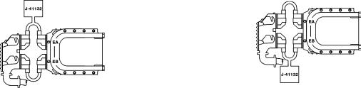
EECU (D12B and D12C), Breakout Box Connected to Wiring Harness Only
For the measurements below, the following applies:
•Breakout box J-41132 connected to connector EA or EB.
•
•
•
The EECU not connected.
Ignition key must be in the OFF position.
Measuring resistance.
|
|
|
|
W2002713 |
|
|
W2002711 |
|
Fig. 9: EECU harness checks, EB |
|
|
|
|
|
|
|
|
Fig. 8: EECU harness checks, EA |
|
|
|
|
|
|
|
|
|
|
|
Connec- |
Signal type |
Measuring points |
|
Ignition key in the OFF position |
Other |
tion |
|
|
|
|
|
|
|
|
|
|
|
EA1 |
Oil temperature sensor, signal |
EA1 / EA5 |
|
1.9 k (+20 C/68 F) |
|
|
|
|
|
100 (+100 C/212 F) |
|
|
|
|
|
|
|
EA2 |
Intake manifold temperature sensor, |
EA2 / EA5 |
|
6.2 k (+20 C/68 F) |
|
|
signal |
|
|
2.5 k (+40 C/104 F) |
|
|
|
|
|
|
|
EA3 |
Intake manifold pressure sensor, sig- |
|
|
|
|
|
nal |
|
|
|
|
|
|
|
|
|
|
EA4 |
Sensor supply (5 V), + |
|
|
|
|
|
|
|
|
|
|
EA5 |
Sensor ground |
|
|
|
|
|
|
|
|
|
|
EA6 |
Not currently used |
|
|
|
|
|
|
|
|
|
|
EA7 |
Engine position sensor (cam), + |
EA7 / EA18 |
|
775 - 945 |
|
|
|
|
|
|
|
EA8 |
Not currently used |
|
|
|
|
|
|
|
|
|
|
EA9 |
Not currently used |
|
|
|
|
|
|
|
|
|
|
EA10 |
Not currently used |
|
|
|
|
|
|
|
|
|
|
EA11 |
Unit injector cylinder 1, - |
EA11 / EA12 |
|
1.5 - 2.0 |
|
|
|
|
|
|
|
EA12 |
Unit injector cylinder 1, 2, 3 (90 |
|
|
see EA11, EA22 and EA23 |
|
|
Volt), + |
|
|
|
|
|
|
|
|
|
|
EA13 |
Fuel temperature sensor, signal |
|
|
|
D12 C |
|
|
|
|
|
|
EA14 |
Oil pressure sensor, signal |
|
|
|
|
|
|
|
|
|
|
EA15 |
Not currently used |
|
|
|
|
|
|
|
|
|
|
EA16 |
Not currently used |
|
|
|
|
|
|
|
|
|
|
EA17 |
Not currently used |
|
|
|
|
|
|
|
|
|
|
EA18 |
Engine position sensor (cam), - |
|
|
see EA7 |
|
|
|
|
|
|
|
EA19 |
Not currently used |
|
|
|
|
|
|
|
|
|
|
EA20 |
Not currently used |
|
|
|
|
|
|
|
|
|
|
19
Group 28 |
|
|
|
Specifications |
|
|
|
|
|
Connec- |
Signal type |
Measuring points |
Ignition key in the OFF position |
Other |
tion |
|
|
|
|
|
|
|
|
|
EA21 |
Not currently used |
|
|
|
|
|
|
|
|
EA22 |
Unit injector cylinder 2, - |
EA22 / EA12 |
1.5 - 2.0 |
|
|
|
|
|
|
EA23 |
Unit injector cylinder 3, - |
EA23 / EA12 |
1.5 - 2.0 |
|
|
|
|
|
|
EA24 |
Unit injector cylinder 4, 5, 6 (90 |
|
see EA34, EA35, and EA36 |
|
|
Volt), + |
|
|
|
|
|
|
|
|
EA25 |
Coolant temperature sensor, signal |
EA25 / EA5 |
1.9 k (+20 C/68 F) |
|
|
|
|
160 (+85 C/185 F) |
|
|
|
|
|
|
EA26 |
Fuel pressure sensor, signal |
|
|
D12 C |
|
|
|
|
|
EA27 |
Not currently used |
|
|
|
|
|
|
|
|
EA28 |
Not currently used |
|
|
|
|
|
|
|
|
EA29 |
Not currently used |
|
|
|
|
|
|
|
|
EA30 |
Engine speed sensor (crank), + |
EA30 / EA31 |
775 - 945 |
|
|
|
|
|
|
EA31 |
Engine speed sensor (crank), - |
EA31 / EA30 |
775 - 945 |
|
|
|
|
|
|
EA32 |
Not currently used |
|
|
|
|
|
|
|
|
EA33 |
VCB, - |
|
|
|
|
|
|
|
|
EA34 |
Unit injector cylinder 4, - |
EA34 / EA24 |
1.5 - 2.0 |
|
|
|
|
|
|
EA35 |
Unit injector cylinder 5, - |
EA35 / EA24 |
1.5 - 2.0 |
|
|
|
|
|
|
EA36 |
Unit injector cylinder 6, - |
EA36 / EA24 |
1.5 - 2.0 |
|
|
|
|
|
|
EB1 |
SAE J1939 + Communications link |
|
|
|
|
|
|
|
|
EB2 |
SAE J1939 - Communications link |
|
|
|
|
|
|
|
|
EB3 |
Ambient air temperature sensor, sig- |
EB3 / EB13 |
6.2 k (+20 C/68 F) |
|
|
nal |
|
1.7 k (+50 C/122 F) |
|
|
|
|
|
|
EB4 |
Buffered idle validation switch |
|
|
|
|
|
|
|
|
EB5 |
Pre-heat sense 1 (if equipped) |
EB5 / EB9 |
open circuit (open) |
|
|
|
|
< 5.0 (closed) |
|
|
|
|
|
|
EB6 |
Not currently used |
|
|
|
|
|
|
|
|
EB7 |
Coolant level sensor, signal |
EB7 / EB8 |
open circuit (coolant level normal) |
Applies to WX , VN |
|
|
|
<1 ; closed (coolant level low) |
and VHD |
|
|
|
|
|
EB8 |
Sensors ground |
|
|
|
|
|
|
|
|
EB9 |
EECU ground, - |
|
|
|
|
|
|
|
|
EB10 |
EECU ground, - |
|
|
|
|
|
|
|
|
EB11 |
EECU B+ |
|
|
|
|
|
|
|
|
EB12 |
EECU B+ |
|
|
|
|
|
|
|
|
EB13 |
Ambient air temperature sensor |
|
|
|
|
|
|
|
|
EB14 |
Not currently used |
|
|
|
|
|
|
|
|
EB15 |
Not currently used |
|
|
|
|
|
|
|
|
EB16 |
Pre-heat sensor 2 (if equipped) |
EB16 / EB9 |
open circuit (open) |
|
|
|
|
< 5.0 (closed) |
|
|
|
|
|
|
EB17 |
Air filter indicator sensor signal |
|
|
|
|
|
|
|
|
EB18 |
Not currently used |
|
|
|
|
|
|
|
|
EB19 |
Not currently used |
|
|
|
|
|
|
|
|
20
Group 28 |
|
|
|
Specifications |
|
|
|
|
|
Connec- |
Signal type |
Measuring points |
Ignition key in the OFF position |
Other |
tion |
|
|
|
|
|
|
|
|
|
EB20 |
Not currently used |
|
|
|
|
|
|
|
|
EB21 |
Engine fan control (if equipped with |
|
|
|
|
on/off fan) |
|
|
|
|
|
|
|
|
EB22 |
Not currently used |
|
|
|
|
|
|
|
|
EB23 |
Not currently used |
|
|
|
|
|
|
|
|
EB24 |
EOL Enable |
EB24/EB9 |
Open circuit(open) |
|
|
|
|
|
|
|
|
EB25 / (connection |
<1 |
|
|
|
A in the 6 pin diag- |
|
|
|
|
nostics connector) |
|
|
EB25 |
SAE J1587/J1708 A Information link |
|
|
|
EB25 / DCA (con- |
<1 |
|
||
|
|
|
||
|
|
nection F in the 9 |
|
|
|
|
pin diagnostics con- |
|
|
|
|
nector) |
|
|
|
|
|
|
|
|
|
EB26 / (connection |
<1 |
|
|
|
B in the 6 pin diag- |
|
|
EB26 |
SAE J1587/J1708 B Information link |
nostics connector) |
|
|
|
|
|
||
EB26 / (connection |
<1 |
|
||
|
|
|
||
|
|
G in the 9 pin diag- |
|
|
|
|
nostics connector) |
|
|
|
|
|
|
|
EB27 |
Not currently used |
|
|
|
|
|
|
|
|
EB28 |
Not currently used |
|
|
|
|
|
|
|
|
EB29 |
Not currently used |
|
|
|
|
|
|
|
|
EB30 |
Not currently used |
|
|
|
|
|
|
|
|
EB31 |
Preheating relay coil ground (if |
|
|
|
|
equipped) |
|
|
|
|
|
|
|
|
EB32 |
Not currently used |
|
|
|
|
|
|
|
|
EB33 |
Not currently used |
|
|
|
|
|
|
|
|
EB34 |
Not currently used |
|
|
|
|
|
|
|
|
EB35 |
EPG 1, - |
|
|
|
|
|
|
|
|
EB36 |
EPG 2, - |
|
|
|
|
|
|
|
|
21
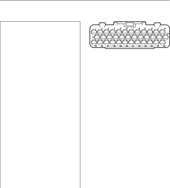
Group 28
Pinouts
Engine Electronic Control Unit (EECU)
VOLVO D12B/D12C EECU/EA Connector
Cavity |
|
Color |
|
Description |
|
|
|
|
|
|
|
|
|
1 |
|
GN |
|
OIL TEMPERATURE |
|
|
|
|
|
|
|
|
|
2 |
|
BL/W |
|
BOOST TEMPERATURE |
|
|
|
|
|
|
|
|
|
3 |
|
GR |
|
BOOST PRESSURE |
|
|
|
|
|
|
|
||
4 |
|
GN/W |
|
BOOST & OIL PRESSURE COMMON (+) |
||
|
|
|
|
|
||
5 |
|
BN/W |
|
PRESSURE & TEMP. SENSOR COMMON |
||
|
|
|
|
(-) |
|
|
|
|
|
|
|
|
|
6 |
|
|
|
NOT USED |
|
|
|
|
|
|
|
||
7 |
|
Y |
|
ENGINE POSITION SENSOR, CAM (+) |
||
|
|
|
|
|
|
|
8-10 |
|
|
|
NOT USED |
|
|
|
|
|
|
|
|
|
11 |
|
W |
|
INJECTOR, CYL 1 (-) |
|
|
|
|
|
|
|
||
12 |
|
W |
|
CYL 1, CYL 2, CYL 3 INJECTOR COM- |
||
|
|
|
|
MON, 90 Volt (+) |
|
|
|
|
|
|
|
||
13 |
|
GN |
|
FUEL TEMPERATURE (D12C) |
||
|
|
|
|
|
|
|
14 |
|
BN |
|
OIL PRESSURE |
|
|
|
|
|
|
|
|
|
15-17 |
|
|
|
NOT USED |
|
|
|
|
|
|
|
||
18 |
|
BN/W |
|
ENGINE POSITION SENSOR, CAM (-) |
||
|
|
|
|
|
|
|
19-21 |
|
|
|
NOT USED |
|
|
|
|
|
|
|
|
|
22 |
|
W |
|
INJECTOR, CYL 2 (-) |
|
|
|
|
|
|
|
|
|
23 |
|
W |
|
INJECTOR, CYL 3 (-) |
|
|
|
|
|
|
|
||
24 |
|
W |
|
CYL 4, CYL 5, CYL 6 INJECTOR COM- |
||
|
|
|
|
MON, 90 Volt (+) |
|
|
|
|
|
|
|
||
25 |
|
Y/W |
|
COOLANT TEMPERATURE |
||
|
|
|
|
|
|
|
26 |
|
|
|
NOT USED |
|
|
|
|
|
|
|
|
|
27 |
|
BN |
|
FUEL PRESSURE (D12C) |
|
|
|
|
|
|
|
|
|
28-29 |
|
|
|
NOT USED |
|
|
|
|
|
|
|
||
30 |
|
BL/SB |
|
ENGINE SPEED SENSOR, CRANK (+) |
||
|
|
|
|
|
||
31 |
|
BL/R |
|
ENGINE SPEED SENSOR, CRANK (-) |
||
|
|
|
|
|
|
|
32 |
|
|
|
NOT USED |
|
|
|
|
|
|
|
||
33 |
|
GN/W |
|
VCB SOLENOID VALVE RETURN |
||
|
|
|
|
|
|
|
34 |
|
W |
|
INJECTOR, CYL 4 (-) |
|
|
|
|
|
|
|
|
|
35 |
|
W |
|
INJECTOR, CYL 5 (-) |
|
|
|
|
|
|
|
|
|
36 |
|
W |
|
INJECTOR, CYL 6 (-) |
|
|
|
|
|
|
|
|
|
Wire Colors: |
BL |
BLUE |
R |
RED |
||
|
|
BN |
BROWN |
SB |
SOLID BLACK |
|
|
|
GN |
GREEN |
VO |
VIOLET |
|
|
|
GR |
GRAY |
W |
WHITE |
|
|
|
OR |
ORANGE |
Y |
YELLOW |
|
|
|
P |
PINK |
|
|
|
Specifications
W3000945
22
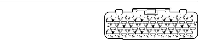
Group 28 Specifications
VOLVO D12B/D12C EECU/EB Connector |
|
||||||
|
|
|
|
|
|
|
|
Cavity |
|
Color |
|
Description |
|
|
|
|
|
|
|
|
|
||
1 |
|
Y |
|
DATA LINK J1939 CAN HI |
|
||
|
|
|
|
|
|
||
2 |
|
GN |
|
DATA LINK J1939 CAN LO |
|
||
|
|
|
|
|
|
||
3 |
|
BL/Y |
|
AMBIENT AIR TEMPERATURE |
|
||
|
|
|
|
|
|
|
W3000945 |
4 |
|
P |
|
BUFFERED IDLE VALIDATION |
|||
|
|
|
|||||
|
|
|
|
SWITCH |
|
|
|
|
|
|
|
|
|
|
|
5 |
|
R |
|
PREHEAT SENSE 1 |
|
|
|
|
|
|
|
|
|
|
|
6 |
|
|
|
NOT USED |
|
|
|
|
|
|
|
|
|
||
7 |
|
BL/SB |
|
COOLANT LEVEL WARNING |
|
||
|
|
|
|
|
|
||
8 |
|
GR/W |
|
AIR FILTER, COOL LVL COMMON |
|
||
|
|
|
|
|
|
|
|
9 |
|
W |
|
GROUND (-) |
|
|
|
|
|
|
|
|
|
|
|
10 |
|
W |
|
GROUND (-) |
|
|
|
|
|
|
|
|
|
|
|
11 |
|
R/SB |
|
POWER SUPPLY (+) |
|
|
|
|
|
|
|
|
|
|
|
12 |
|
R/SB |
|
POWER SUPPLY (+) |
|
|
|
|
|
|
|
|
|
||
13 |
|
V0/W |
|
AMBIENT AIR TEMP COMMON (-) |
|
||
|
|
|
|
|
|
|
|
14-15 |
|
|
|
NOT USED |
|
|
|
|
|
|
|
|
|
|
|
16 |
|
R/W |
|
PREHEAT SENSE 2 |
|
|
|
|
|
|
|
|
|
||
17 |
|
BL/R |
|
AIR FILTER INDICATOR |
|
||
|
|
|
|
|
|
|
|
18-20 |
|
|
|
NOT USED |
|
|
|
|
|
|
|
|
|
||
21 |
|
GR/R |
|
COOLING FAN CONTROL (-) |
|
||
|
|
|
|
|
|
|
|
22-23 |
|
|
|
NOT USED |
|
|
|
|
|
|
|
|
|
||
24 |
|
Y/SB |
|
FACTORY PROGRAMMING (NOT |
|
||
|
|
|
|
USED) |
|
|
|
|
|
|
|
|
|
||
25 |
|
GR |
|
DATA LINK J1708/1587 (+) |
|
||
|
|
|
|
|
|
||
26 |
|
OR |
|
DATA LINK J1708/1587 (-) |
|
||
|
|
|
|
|
|
|
|
27-30 |
|
|
|
NOT USED |
|
|
|
|
|
|
|
|
|
||
31 |
|
BL/R |
|
PREHEAT RELAY(Coil Ground) |
|
||
|
|
|
|
|
|
|
|
32-34 |
|
|
|
NOT USED |
|
|
|
|
|
|
|
|
|
|
|
35 |
|
GR/SB |
|
EPG1 CONTROL |
|
|
|
|
|
|
|
|
|
|
|
36 |
|
GR/W |
|
EPG2 CONTROL |
|
|
|
|
|
|
|
|
|
|
|
Wire Colors: |
BL |
BLUE |
R |
RED |
|||
|
|
BN |
BROWN |
SB |
SOLID BLACK |
||
|
|
GN |
GREEN |
VO |
VIOLET |
||
|
|
GR |
GRAY |
W |
WHITE |
||
|
|
OR |
ORANGE |
Y |
YELLOW |
||
|
|
P |
PINK |
|
|
|
|
23
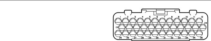
Group 28 Specifications
|
VOLVO D7C EECU/EA Connector |
|
|||
|
|
|
|
|
|
Cavity |
Color |
Description |
|
|
|
|
|
|
|
|
|
1 |
GN |
OIL TEMPERATURE |
|
|
|
|
|
|
|
|
|
2 |
BL/W |
BOOST TEMPERATURE |
|
|
|
|
|
|
|
|
W3000945 |
3 |
GR |
BOOST PRESSURE |
|
||
|
|
||||
|
|
|
|
||
4 |
GN/W |
BOOST, OIL & FUEL PRESSURE COMMON (+) |
|
||
|
|
|
|
||
5 |
BN/W |
PRESSURE & TEMP. SENSOR COMMON |
|
||
|
|
|
|
|
|
6 |
|
NOT USED |
|
|
|
|
|
|
|
||
7 |
Y |
REDUNDANT ENGINE SPEED SENSOR (+) |
|
||
|
|
|
|
|
|
8 |
Y/R |
RACK DRIVE, PWM (+) |
|
|
|
|
|
|
|
|
|
9 |
Y/SB |
TIMING SLEEVE, PWM |
|
|
|
|
|
|
|
|
|
10 |
GN/BN |
RACK DRIVE, PWM (-) |
|
|
|
|
|
|
|
|
|
11-12 |
|
NOT USED |
|
|
|
|
|
|
|
|
|
13 |
GN/BN |
FUEL TEMPERATURE |
|
|
|
|
|
|
|
|
|
14 |
BN |
OIL PRESSURE |
|
|
|
|
|
|
|
||
15 |
GR/SB |
NEEDLE LIFT SENSOR(+) |
|
||
|
|
|
|
||
16 |
BL/R |
RACK POSITION SENSOR, SEARCH COIL |
|
||
|
|
|
|
||
17 |
Y/GR |
RACK POSITION SENSOR, COMMON |
|
||
|
|
|
|
||
18 |
BN/W |
REDUNDANT ENGINE SPEED SENSOR (-) |
|
||
|
|
|
|
|
|
19-20 |
|
NOT USED |
|
|
|
|
|
|
|
||
21 |
OR |
TIMING SLEEVE, PWM (-) |
|
||
|
|
|
|
|
|
22-24 |
|
NOT USED |
|
|
|
|
|
|
|
||
25 |
Y/W |
COOLANT TEMPERATURE |
|
||
|
|
|
|
|
|
26 |
|
NOT USED |
|
|
|
|
|
|
|
|
|
27 |
BN |
FUEL PRESSURE |
|
|
|
|
|
|
|
||
28 |
GR/R |
NEEDLE LIFT SENSOR (-) |
|
||
|
|
|
|
||
29 |
Y/W |
RACK POSITION SENSOR, REFERENCE COIL |
|
||
|
|
|
|
||
30 |
BL/SB |
ENGINE SPEED SENSOR, CRANK(+) |
|
||
|
|
|
|
||
31 |
BL/R |
ENGINE SPEED SENSOR, CRANK(-) |
|
||
|
|
|
|
|
|
32-36 |
|
NOT USED |
|
|
|
|
|
|
|
|
|
Wire Colors: BL |
BLUE |
R |
RED |
||
|
BN |
BROWN |
SB |
SOLID BLACK |
|
|
GN |
GREEN |
VO |
VIOLET |
|
|
GR |
GRAY |
W |
WHITE |
|
|
OR |
ORANGE |
Y |
YELLOW |
|
|
P |
PINK |
|
|
|
24

Group 28 Specifications
VOLVO D7C EECU/EB Connector |
|
||||||
|
|
|
|
|
|
|
|
Cavity |
|
Color |
|
Description |
|
|
|
|
|
|
|
|
|
||
1 |
|
Y |
|
DATA LINK J1939 CAN HI |
|
||
|
|
|
|
|
|
||
2 |
|
GN |
|
DATA LINK J1939 CAN LO |
|
||
|
|
|
|
|
|
||
3 |
|
BL/Y |
|
AMBIENT AIR TEMPERATURE |
|
||
|
|
|
|
|
|
|
W3000945 |
4 |
|
P |
|
BUFFERED IDLE VALIDATION |
|||
|
|
|
|||||
|
|
|
|
SWITCH |
|
|
|
|
|
|
|
|
|
|
|
5 |
|
R |
|
PREHEAT SENSE 1 |
|
|
|
|
|
|
|
|
|
|
|
6 |
|
|
|
NOT USED |
|
|
|
|
|
|
|
|
|
||
7 |
|
BL/SB |
|
COOLANT LEVEL WARNING |
|
||
|
|
|
|
|
|
||
8 |
|
GR/W |
|
AIR FILTER, COOL LEVEL COM- |
|
||
|
|
|
|
MON (-) |
|
|
|
|
|
|
|
|
|
|
|
9 |
|
W |
|
GROUND (-) |
|
|
|
|
|
|
|
|
|
|
|
10 |
|
W |
|
GROUND (-) |
|
|
|
|
|
|
|
|
|
|
|
11 |
|
R/SB |
|
POWER SUPPLY (+) |
|
|
|
|
|
|
|
|
|
|
|
12 |
|
R/SB |
|
POWER SUPPLY (+) |
|
|
|
|
|
|
|
|
|
||
13 |
|
V0/W |
|
AMBIENT AIR TEMP COMMON (-) |
|
||
|
|
|
|
|
|
|
|
14-16 |
|
|
|
NOT USED |
|
|
|
|
|
|
|
|
|
||
17 |
|
BL/R |
|
AIR FILTER INDICATOR |
|
||
|
|
|
|
|
|
|
|
18-23 |
|
|
|
NOT USED |
|
|
|
|
|
|
|
|
|
||
24 |
|
Y/SB |
|
FACTORY PROGRAMMING (NOT |
|
||
|
|
|
|
USED) |
|
|
|
|
|
|
|
|
|
||
25 |
|
GR |
|
DATA LINK J1708/1587 (+) |
|
||
|
|
|
|
|
|
||
26 |
|
OR |
|
DATA LINK J1708/1587 (-) |
|
||
|
|
|
|
|
|
|
|
27-30 |
|
|
|
NOT USED |
|
|
|
|
|
|
|
|
|
||
31 |
|
BL/R |
|
PREHEAT RELAY, CONTROL |
|
||
|
|
|
|
|
|
|
|
32-33 |
|
|
|
NOT USED |
|
|
|
|
|
|
|
|
|
||
34 |
|
Y/BN |
|
FUEL SHUTOFF VALVE CONTROL |
|
||
|
|
|
|
|
|
|
|
35 |
|
GR |
|
EPG1 |
|
|
|
|
|
|
|
|
|
|
|
36 |
|
|
|
NOT USED |
|
|
|
|
|
|
|
|
|
|
|
Wire Colors: |
BL |
BLUE |
R |
RED |
|||
|
|
BN |
BROWN |
SB |
SOLID BLACK |
||
|
|
GN |
GREEN |
VO |
VIOLET |
||
|
|
GR |
GRAY |
W |
WHITE |
||
|
|
OR |
ORANGE |
Y |
YELLOW |
||
|
|
P |
PINK |
|
|
|
|
25

Group 28
Pinouts
Vehicle Electronic Control Unit(VECU)
Vehicle ECU Connector A-(GREEN)
Cavity |
Circuit |
Description |
|
|
|
1 |
564A |
CC/PTO SWITCH SET(-) INPUT |
|
|
|
2 |
563A |
CC/PTO SWITCH SET(+) INPUT |
|
|
|
3 |
562A |
CC/PTO SWITCH ON INPUT |
|
|
|
4 |
|
NOT USED |
|
|
|
5 |
567B |
SERVICE BRAKE SWITCH INPUT |
|
|
|
6 |
284-A |
12V STARTER CONTROL SOLE- |
|
|
NOID FEED |
|
|
|
7 |
245 |
ENGINE PREHEAT CIRCUIT PRO- |
|
|
TECTION FEED |
|
|
|
8 |
571 |
CLUTCH SWITCH INPUT |
|
|
|
9 |
385-A |
PARK CONTROL WIPER MOTOR |
|
|
|
10 |
388 |
INTERMITTENT WIPER INPUT |
|
|
|
11 |
387-C |
SWITCH TO WASHER MOTOR |
|
|
|
12 |
0XE |
ELECTRONIC GROUND |
|
|
|
13 |
18V |
ELECTRONIC ENGINE SWITCHED |
|
|
BATTERY FEED |
|
|
|
14 |
196V |
IGNITION SWITCH DR FEED |
|
|
|
15-18 |
|
NOT USED |
|
|
|
19 |
300D |
MANUAL FAN SWITCH INPUT |
|
|
|
20 |
629 |
ENGINE BRAKE MEDIUM FEED |
|
|
|
21 |
628 |
ENGINE BRAKE LOW FEED |
|
|
|
22 |
|
NOT USED |
|
|
|
23 |
555 |
IDLE VALIDATION INPUT |
|
|
|
24 |
682 |
HIGH REFRIGERANT PRESSURE |
|
|
SWITCH FEED |
|
|
|
25-28 |
|
NOT USED |
|
|
|
29 |
573 |
PTO SWITCH ON INPUT |
|
|
|
30 |
565A |
CC/PTO SWITCH RESUME INPUT |
|
|
|
Specifications
W3002689
26
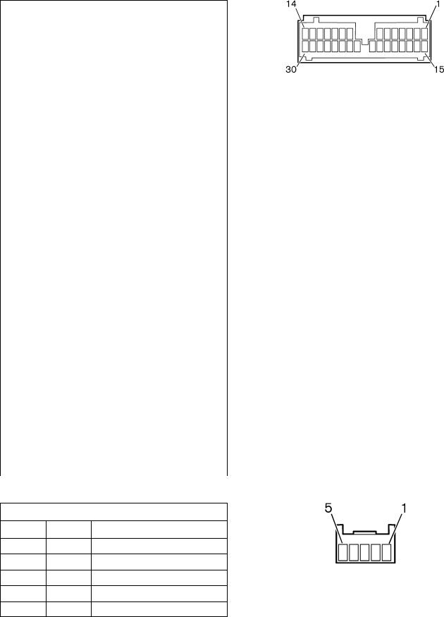
Group 28 |
Specifications |
Vehicle ECU Connector B-(BLUE)
Cavity |
Circuit |
Description |
|
|
|
1 |
|
NOT USED |
|
|
|
2 |
312A |
TRANSMISSION AREA INHIBITOR |
|
|
VALVE RETURN |
|
|
|
3-4 |
|
NOT USED |
|
|
|
5 |
597 |
ECU COMMON 12V OUTPUT |
|
|
|
6 |
550 |
VEHICLE SPEED INPUT |
|
|
|
7 |
|
NOT USED |
|
|
|
8 |
553 |
THROTTLE POSITION SENSOR IN- |
|
|
PUT |
|
|
|
9 |
|
NOT USED |
|
|
|
10 |
552 |
THROTTLE POSITION SENSOR |
|
|
SUPPLY |
|
|
|
11 |
581 |
PARKING BRAKE SWITCH INPUT |
|
|
|
12-14 |
|
NOT USED |
|
|
|
15 |
583 |
POWER CONTROL FROM ENGINE |
|
|
ECU |
|
|
|
16 |
389B |
INTERMITTENT WIPER RELAY |
|
|
COIL RETURN |
|
|
|
17 |
555A |
IDLE VALIDATION FROM ENGINE |
|
|
ECU |
|
|
|
18 |
312C |
RANGE INHIBITOR VALVE RETURN |
|
|
|
19 |
558 |
ECU COMMON +12V OUTPUT |
|
|
|
20 |
551 |
VEHICLE SPEED RETURN FROM |
|
|
ECU |
|
|
|
21 |
317B |
TRANSMISSION LOW RANGE INDI- |
|
|
CATOR SIGNAL |
|
|
|
22 |
554 |
THROTTLE POSITION SENSOR RE- |
|
|
TURN |
|
|
|
23-26 |
|
NOT USED |
|
|
|
27 |
567A |
SERVICE BRAKE SWITCH INPUT |
|
|
|
28-30 |
|
NOT USED |
|
|
|
Vehicle ECU Connector C-(GREEN)
Cavity Circuit Description
1401-D DATA LINK J1708 (-)
2400-D DATA LINK J1708 (+)
3408-B DATA LINK J1939 SHIELD
4406-B DATA LINK J1939 CAN HI
5407-B DATA LINK J1939 CAN LOW
W3002689
W3002690
27

Group 28 |
Specifications |
Schematic
D12B
W2002827
28
 Loading...