


Service Manual
Trucks
Group 177–500
Preventive Maintenance
Basic Service
VN,VHD
PV776-TSP151476
Foreword
The descriptions and service procedures contained in this manual are based on designs and methods studies carried out up to December 2001.
The products are under continuous development. Vehicles and components produced after the above date may therefore have different specifications and repair methods. When this is believed to have a significant bearing on this manual, supplementary service bulletins will be issued to cover the changes.
The new edition of this manual will update the changes.
In service procedures where the title incorporates an operation number, this is a reference to an S.R.T. (Standard Repair Time).
Service procedures which do not include an operation number in the title are for general information and no reference is made to an S.R.T.
The following levels of observations, cautions and warnings are used in this Service Documentation:
Note: Indicates a procedure, practice, or condition that must be followed in order to have the vehicle or component function in the manner intended.
Caution: Indicates an unsafe practice where damage to the product could occur.
Warning: Indicates an unsafe practice where personal injury or severe damage to the product could occur.
Danger: Indicates an unsafe practice where serious personal injury or death could occur.
Volvo Trucks North America, Inc.
Greensboro, NC USA
Order number: PV776-TSP151476
© 2001 Volvo Trucks North America, Inc., Greensboro, NC USA
All rights reserved. No part of this publication may be reproduced, stored in retrieval system, or transmitted in any forms by any means, electronic, mechanical, photocopying, recording or otherwise, without the prior written permission of Volvo Trucks North America, Inc..
Contents |
|
General .................................................................................................... |
3 |
Preventive Maintenance, General ........................................................... |
3 |
Safety Advice ......................................................................................... |
7 |
Specifications ......................................................................................... |
9 |
Engine .................................................................................................... |
9 |
Transmission ........................................................................................ |
12 |
Rear Axle ............................................................................................. |
13 |
Tools ...................................................................................................... |
14 |
Special Tools and Special Equipment ................................................. |
14 |
Preventive Maintenance Inspection Bay ............................................. |
21 |
Design and Function ........................................................................... |
23 |
Clutch ................................................................................................... |
23 |
Power Take-off ..................................................................................... |
25 |
Driveshaft ............................................................................................. |
25 |
Brakes .................................................................................................. |
26 |
Steering System .................................................................................. |
27 |
Hubs .................................................................................................... |
28 |
Chassis ................................................................................................ |
29 |
Cab ...................................................................................................... |
30 |
Preventive Maintenance ...................................................................... |
31 |
Basic Service ....................................................................................... |
31 |
............................................................................................................... |
97 |
Additional Time Based Maintenance ..................................................... |
97 |
............................................................................................................... |
99 |
Additional Mileage Based Maintenance ................................................ |
99 |
Feedback |
|
1
2

Group 177 |
General |
General
Preventive Maintenance, General
Introduction
This manual describes inspection and lubrication requirements during the Basic Service of Volvo VN/VHD vehicles. The purpose for doing the preventive maintenance is to ensure that the vehicle is safe and roadworthy over its full lifetime.
The driver is taking part in the continuous preventive maintenance program by completing the required Daily Pre-trip Inspection. This is a purely visual inspection that is designed to detect any obvious problems that would make the vehicle unsafe to take on the road. Added to the Pre-trip Inspection is the Preventive Maintenance Program that is typically carried out by trained personnel using a systematic approach to cover all important components of the new vehicle.
Preventive Maintenance is a planned vehicle maintenance program that provides an orderly series of servicing and inspecting procedures. A well applied maintenance program realizes the investment made in the vehicle. The difference between a poorly maintained vehicle and a well maintained vehicle will not show up until later mileage. Good maintenance is necessary to assure the designed life expectancy of the vehicle and its individual components.
Maintenance Coverage
There is no firm maintenance program that will apply to all operations. A basic maintenance program is not difficult to set up; to make the program the most effective takes time and effort, and is based around the needs and experiences of each individual operation. The program in this service manual covers all types of Volvo VN/VHD vehicles with medium to high mileage and sometimes high loads.
Use this established maintenance program as a base to tailor an individual maintenance program for customers that have requirements that are outside of the scope of this program.
To establish an individual program, look at information sources that are usually available, such as:
Driver’s repair or complaint reports. Unusual parts usage.
Repetitive failures or problems found in inspection. Unscheduled maintenance or repairs.
Road failures.
3
Group 177 |
General |
Program Structure
This maintenance program has been based on the progress in vehicle technology and increases in oil quality to simplify the maintenance.
For simplified scheduling, the program has tied maintenance to logical time or mileage limits that make it easy to anticipate needed servicing. For the majority of onhighway operators, the 24,000 km (15,000 miles) or 4 months schedule can be used with little change.
It is important that the scheduled intervals are followed as limits. Maintenance can be done before either 24,000 km (15,000 miles) have been reached or before 4 months are up but must be made at or before either the mileage or the time limit has been reached.
For further information concerning component specifications see service information in Group 1, “Oil and Filter Change Intervals for Volvo Components, All Models”, Publication Number 175–001, and any appropriate vendor literature.
Advantages
A well-planned preventive maintenance program offers the following advantages:
The lowest attainable maintenance cost.
Maximum vehicle uptime.
Better fuel economy.
Reduced road failures; greater dependability.
Increased customer confidence, better public relations.
Less possibility of accidents due to defective equipment.
Fewer driver complaints.
Regardless of the planning and the details of the maintenance program, the success of the program hinges on the caliber of workmanship in performing the actual inspection. A major cause of failure is a “pencil inspection;” that is, the mechanic checks off each operation as being OK without making the actual inspection. A “pencil inspection” defeats the purpose of the inspection, which is to detect an impending failure.
Maintenance Form
A Service Manual is issued detailing the current inspection forms. Forms are created for different users but all with the same references to this document. When the inspection point is carried out, check the box if the item is OK. If further work, such as adjustment, repair, etc., needs to be performed, record this information and go on with the next inspection point. Items noted as being faulty or in need of adjustment need to be shown to the customer and scheduled for repair.
There are many time — and/or mileage-based — service items that are not listed on the form. Look at the end of this document for a listing of additional components that may need to be serviced, depending on the mileage or time since last service.
Maintenance Records
It is important to use the inspection form together with other reports to come up with the best maintenance program for a specific application. Use driver’s reports, complaints, parts usage, repetitive failures, previous repair orders, road failures, etc. to build a maintenance history.
Records should be collected over the lifetime of the vehicle to form a permanent vehicle record file. The vehicle file should be used to customize the operational maintenance needs.
The “Driver Inspection Form” is also required by Federal law. The use of this inspection report makes the driver a part of the maintenance program and places direct responsibility on the driver to report problems that may come up during operation. When properly used, there should be no excuse for a defective vehicle being in service.
Basic Inspection
Note: The included Basic Service checklist is an original copy. The document can be updated without notice.
The Basic inspection is carried out at a maximum of 24,000 km (15,000 miles) or 4 months, whichever comes first.
All inspection points are to be carried out as verification of function or condition. Any defects are noted on the inspection form for later correction, if so ordered by the vehicle owner.
Note: The standard repair time for performing the Basic Service Preventive Maintenance is based on inspection and Oil and Filter Change, without repair or adjustment.
Annual Inspection
The Annual inspection is carried out yearly in addition to a Basic inspection. This inspection is designed to open up components for inspection or using test equipment to record performance.
The ideal time to carry out the Annual inspection is right before the hardest season, which means just before winter in the cold weather climates and just before summer in the hot weather climates.
For further information refer to “Annual Preventive Service Manual”, Publication Number 177–501.
4
Group 177 |
General |
Other Inspection
There are additional service points that are carried out at specific mileage or time intervals. These are not part of the Preventive Maintenance Basic time. They should be scheduled as an adjustment or repair job carried out at the same time as the Preventive Maintenance, and are listed in this document as reminders only.
5
Group 177 |
General |
Noise Emissions
Volvo Trucks North America, Inc. warrants to the first person who purchases this vehicle for purposes other than resale and to each subsequent purchaser, that this vehicle as manufactured by Volvo Trucks North America, Inc. was designed, built and equipped to conform, to all applicable U.S. EPA Noise Control Regulations, at the time it left the control of Volvo Trucks North America, Inc.
This warranty covers this vehicle as designed, built and equipped by Volvo Trucks North America, Inc., and is not limited to any particular part, component or system of the vehicle manufactured by Volvo Trucks North America, Inc. Defects in design, assembly or in any part, component or system of the vehicle as manufactured by Volvo Trucks North America, Inc., which, at the time it left the control of Volvo Trucks North America, Inc. caused noise emissions to exceed Federal standards, are covered by this warranty for the life of the vehicle.
Tampering with Noise Control System
Federal law prohibits the following acts or the causing thereof:
(1) The removal or rendering inoperative by any person, other than for purposes of maintenance, repair, or replacement, of any device or element of design incorporated into any new vehicle for the purpose of noise control prior to its sale or delivery to the ultimate purchaser or while it is in use;
or
(2) the use of the vehicle after such device or element of design has been removed or rendered inoperative by any person.
Among those acts presumed to constitute tampering are the acts listed below:
Noise Shields and Insulation
Removing or rendering inoperative the engine and/or transmission noise deadening panels, shields or insulating materials.
Removing or rendering inoperative the cab tunnel or hood noise insulating materials.
Removing or rendering inoperative any truck body mounted sound insulation components and/or shields (e.g., cab or fender shields, skirts, wheel housing splash shields, etc.).
Engine Control and Fuel Systems
Removing or rendering inoperative, or modifying the engine control system (such a the ECU or the fuel system components) in order to allow the engine to operate outside of the manufacturer’s specifications (e.g., exceeding the manufacturer’s engine speed limits).
Cooling System
Removing or rendering inoperative cooling system components (e.g., temperature-controlled fan clutch, fan shroud, fan ring, recirculation shields, etc.).
Exhaust System
Removing or rendering inoperative exhaust system components (e.g., muffler, pipes, clamps, etc.).
Air Intake System
Removing or rendering inoperative air intake/induction system components (e.g., filter, filter housing, ducts, etc.).
6
Group 177 |
General |
Safety Advice
Never operate a diesel engine in an area where hydrocarbon vapors (gasoline for example) are present or are suspected to be present. Hydrocarbon vapors can enter the air intake and make the engine overspeed, causing severe damage and/or explosion or fire. Serious personal injury or death can occur.
When entering and exiting the cab, use caution. Always have a firm hand hold and/or stable foot position before transferring weight to that position. Do not
carry anything when entering or exiting. Make sure the soles of your shoes and the cab steps are free from dirt, grease, oil or moisture before using the steps. Failure to do so can result in a fall, and serious personal injury or death may occur.
Always chock the wheels before working under the vehicle to prevent it from rolling. Failure to do so can result in unexpected vehicle movement and serious personal injury or death could occur.
If using a jack and/or jack stands, choose proper fault-free equipment. Failure to do so can result in equipment failures and personal injury or death may occur.
Note: During the Preventive Maintenance inspection, check the condition of warning labels on the vehicle. If a label is damaged or defaced to the point where the message cannot be read, note on the inspection form to have it replaced.
7
8
Group 177 |
Specifications |
|
|
|
|
Specifications
Engine
General
For further information concerning component specifications see service information in Group 1, “Oil and Filter Change Intervals for Volvo Components,” Publication Number 175–001, and any appropriate vendor literature.
In a modern diesel engine it is very important to have regular oil changes. The demands of pulling high loads, pulling at high elevations, extreme high or low temperatures and longer service intervals, make the choice of correct oil a hard task. The Volvo dealer, the engine manufacturer or the oil manufacturer has the expertise to analyze driving conditions and to recommend what oil gives the best protection and economy.
Oil
The engine oil has the task of lubricating, sealing, cooling and cleaning the engine. Filtering the intake air and using a low sulfur fuel helps the oil protect the engine parts. With better engine designs and improved oils, the service intervals have steadily increased. The interval choice depends on the engine manufacturer specifications. Make sure the correct oil type and also the correct viscosity are chosen for the mileage interval driven.
Periodic oil testing is recommended. The test results give a continuous picture of the health of the engine and can warn well in advance of a problem developing.
The intervals will not cover all applications. In on/off highway driving, severe off highway, continuous stop- and-go city driving and extremely high mileage, the oil change interval and preventive maintenance schedule need to be customized for the best protection and economy. The intervals listed in these specifications are guidelines that should be used in establishing a correct maintenance program.
 CAUTION
Adding unknown additives may put the engine at risk of failure. There are many aftermarket oil additives that claim improved performance if added to the engine oil. Each oil type recommended already contains additives that have been tested by a collaboration with engine and oil manufacturers.
Synthetic oil is offered as an alternative to the traditional petroleum based oil for the engines. The ability of synthetic oil to protect the engine is better than regular oil but its life is the same as for regular oil. This is because
of the combustion by-products that contaminate the oil. These contaminates will make the change intervals the same as for regular oil. However, in extreme driving conditions, a synthetic oil may be the only choice for the application.
Note: It is not recommended to mix synthetic oils with petroleum-based oils.
Coolant
The engine coolant protects the cooling system from freezing or boil over problems. It also protects against corrosion and cylinder liner pitting. Coolant requirements are based on the additive levels present in the cooling system. To be able to run the cooling system as long as 2 years between coolant changes, there must be a replenishment of additives as they are used up. Testing should be done regularly to be sure the additive levels are within recommended levels.
Never run the engine with only water in the cooling system. Always use a mixture of clean water and a recommended antifreeze. The mixture should never be less than 40% antifreeze and 60% clean water or more than 60% antifreeze and 40% clean water.
Note: For further information on Long life coolant refer to Service Bulletin 260–002, “Texaco Extended Life Coolant.”
 CAUTION
Long life coolant is colored red for identification purposes, so as not to mistake it for conventional, green coolant. Long life coolant will test as out of additives (SCA), but SCA should not be added.
Fuel
The sulfur content in low-sulfur fuel has been regulated to a maximum of 0.05% per weight for No.2–D diesel fuel. For fuels that have a sulfur content of 0.5% by weight and above, most engine manufacturers are requiring that oil is changed at shorter intervals. Sulfur creates highly acidic pollutants in the oil that break down the additives at a higher rate. If fuel with a higher sulfur content is used, the engine manufacturers recommend that the oil change intervals be reduced.
9
Group 177 |
Specifications |
|
|
|
|
VOLVO ENGINES
Note: It is not recommended to mix synthetic oils with petroleum based oils.
For further information concerning component specifications see service information in Group 1, “Oil and Filter Change Intervals for Volvo Components,” publication number 175–001, and appropriate vendor literature.
Maximum change intervals are 40,000 km (25,000 miles) if using oil that meets the Volvo Drain Specification (VDS). If the oil does not meet the requirements according to VDS, change intervals should be 24,000 km (15,000 miles). Contact Volvo or a Volvo authorized dealer to obtain a list of approved VDS oils.
Shorter oil change intervals maybe required if the engine is operating in a dusty environment or if frequent stops and starts are made (see oil change interval below).
Supplemental coolant additives are recommended for all Volvo cooling systems. Antifreeze alone does not provide sufficient corrosion protection for heavy duty diesel engines.
If the fuel has a sulfur content exceeding 0.5% by weight, halve the indicated maximum mileage intervals.
Oil filters should always be changed when changing oil.
CUMMINS ENGINES
For further information concerning component specifications see service information in Group 1, “Oil and Filter Change Intervals for Volvo Components,” publication number 175–001, and appropriate vendor literature.
If engine is operating in ambient temperatures consistently below - 20 C (0 F) or above 40 C (100 F), perform maintenance at shorter intervals. Shorter intervals are also required if the engine is operating in a dusty environment or if frequent stops and starts are made.
Oil filters should always be changed when changing oil.
Supplemental coolant additives are recommended for all Cummins cooling systems. Antifreeze alone does not provide sufficient corrosion protection for heavy duty diesel engines.
10
Group 177 |
Specifications |
|
|
|
|
DETROIT DIESEL ENGINES
For further information concerning component specifications see service information in Group 1, “Oil and Filter Change Intervals for Volvo Components,” publication number 175–001, and appropriate vendor literature.
The use of fuels with a sulfur content above 0.5% by weight will require more frequent oil changes. Refer to Detroit Diesel Publications for details. More frequent oil changes are also required if the engine is operating in a dusty environment or if frequent stops and starts are made (see oil change interval below).
Oil filters should always be changed when changing oil.
Supplemental coolant additives are recommended for all Detroit Diesel cooling systems. Antifreeze alone does not provide sufficient corrosion protection for heavy duty diesel engines.
Note: The Detroit Diesel Engine is installed in earlier VN vehicles (from 1996–2000) only.
CATERPILLAR ENGINES
For further information concerning component specifications see service information in Group 1, “Oil and Filter Change Intervals for Volvo Components,” publication number 175–001, and appropriate vendor literature.
Caterpillar does NOT recommend an automatic extension of oil drain intervals with high quality oil, low sulfur fuel and non-severe duty driving. Oil drain intervals can only be extended with an oil analysis program containing the following elements: oil condition and wear metals, trend analysis, fuel consumption and oil consumption.
In areas where fuel sulfur content exceeds 1.5%, choose an oil with a total base number that is within the API CF-4 or CG-4 categories and shorten the oil change period based on oil analysis.
Shorter oil change intervals are required if the engine is operating in a dusty environment or if frequent stops and starts are made (see oil change interval below).
Oil filters should always be changed when changing oil.
Supplemental coolant additives are recommended for all Caterpillar cooling systems. Antifreeze alone does not provide sufficient corrosion protection for heavy duty diesel engines.
Note: Caterpillar Engines were installed in later model
VN vehicles (from 1996–1999) only.
11
Group 177 |
Specifications |
|
|
|
|
Transmission
Includes Volvo, Eaton Fuller, Meritor, and Allison HD Transmissions
For further information concerning component specifications see service information in Group 1, “Oil and Filter Change Intervals for Volvo Components,” publication number 175–001, and appropriate vendor literature.
12
Group 177 |
Specifications |
|
|
|
|
Rear Axle
Includes Volvo, Arvin Meritor, and Eaton Dana Rear Axles
For further information concerning component specifications see service information in Group 1, “Oil and Filter Change Intervals for Volvo Components,” publication number 175–001, and appropriate vendor literature.
13

Group 177 |
Tools |
Tools
Special Tools and Special Equipment
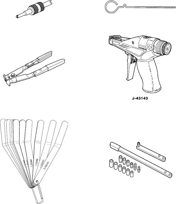
The following special tools are recommended for use in the preventive maintenance inspection. Special tools can be ordered through Volvo Special Tools program in the parts ordering system or already from Kent-Moore by calling (800) 328–6657. (Kent-Moore tools are preceded by a J.) Please refer to the specific tool number when ordering.
Special Tools
J-42942 |
J-42189 |
ABS Sensor Adjustment Tool |
Airline Release Tool |
(Kent-Moore) |
(Kent-Moore) |
J-44399 |
J-44773 |
Air System Tester |
Airline Release Tool |
J-44769 |
J-44966 |
Wheel Speed Sensor Extractor |
Wheel Speed Sensor Remover for Heavy Duty Steer Axle |
|
and Aluminum Hub |
14
Group 177 |
Tools |
Special Tools (Continued)
J-44302 |
J-443338 |
A/C Schrader Valve Core Removal Tool |
Oil Dipstick for A/C Compressor |
J-22610 |
J-43143 |
Drive Shaft Boot Camp Pliers |
Tie Strap Tensioner |
J-41610 |
J-44392 |
Feeler Gauge Set |
Fan Belt Tensioner Tool |
15

Group 177 |
Tools |
Special Tools (Continued)
PT 5900 |
9998142 |
Chip Vacuum |
Charge Air Cooler Pressure Tester |
J-38641-B |
J-44544 |
Diesel Fuel Hydrometer |
Ride Height Gauge |
000700
Rim Flange Wear Gauge
16

Group 177 |
Tools |
Other Special Equipment
J-42397-A |
1089953 |
J-23600-B |
Coolant Pressure Test Adapter |
Bulb Removal Tool |
Belt Tension Gauge |
J-38460-ADigital Inclinometer |
J-36795 |
|
Tandem Axle Calipers |
3093472 |
9996791 |
Timken Wheel End Play Gauge |
Spring Pin Socket |
17

Group 177 |
Tools |
Other Special Equipment (Continued)
9998691 |
3947553, 3949521, 3946522, 3949523 |
Oil Filter Nipple Installer Kit |
Terminal and Shim Kits |
J-44701 |
J-44778, J-44779 |
Battery Tester Kit |
Driveshaft U-Joint and Yoke Kits |
18
Group 177 |
Tools |
VCADS Pro Tools
The following hardware is used to operate VCADS Pro. The tools can be ordered from
Volvo Trucks North America; please refer to the specific tool number when ordering.
|
7 |
|
|
|
1 |
PC tool-package |
5 |
J-43939, 9 pin Diagnostic adapter (for VN vehicles |
|
2 |
9998555, Communication interface unit |
|
built from January 1999) |
|
6 |
9998496, Pressure gauge |
|||
3 |
9812331, Extension cable |
|||
|
|
|||
|
|
7 |
9998495, Air Pressure Hose |
4J-43999, 6 pin Diagnostic adapter (for VN vehicles prior to 1999)
19

Group 177 |
Tools |
Lighting System, Special Tools
The tools listed below are used to complete maintenance on the Lighting System for Volvo Trucks. They may be obtained from Volvo or, where indicated, from Kent Moore at (800) 328-6657.
J-25300-D |
1089953 |
Headlight Aiming Kit (Kent Moore) |
Lamp Removal Tool (Volvo) |
J-42395 |
20378326 |
Rheostat Removal Tool (Kent Moore) |
Fuse Puller Tool (Volvo) |
J-43244
Relay Puller Tool (Kent Moore)
20
Group 177 |
Tools |
Preventive Maintenance Inspection Bay
Location
Preventive Maintenance is logically carried out at the same time as lubrication of the vehicle. It is then natural to use a bay with a grease pit to be assigned and equipped for Preventive Maintenance. If a pit is not available, a regular workshop bay can be used, with jacks added to the necessary equipment.
The bay needs to be well lit so inspection can be done without having to use a flashlight (unless inspecting in the frame).
Equipment
Inspection bay equipment should be specifically assigned to that bay and not be shared with the rest of the shop. The floor equipment should have floor space for storage in between using them and tools should be hung on boards or stored in a cabinet for easy overview and access.
Install mirrors in four corners of the bay so one person can do a lighting function check without having to leave the cab or rely on a spotter. Mirrors do not need to be larger than truck door mirrors. Any type of equipment that allows inspection by one person instead of having to use a helper, makes inspection easier and faster.
21
22

Group 177 |
Design and Function |
Design and Function
Clutch
General
For further information concerning component specifications see service information in Group 1, “Oil and Filter Change Intervals for Volvo Components,” publication number 175–001, and appropriate vendor literature.
Hydraulic fluid in the clutch system collects moisture from the air and will eventually hold enough moisture to affect the metal surfaces in the system unless removed. Replace the fluid at the recommended intervals or more frequently.
The clutch pedal play (1) is given by the clearance between the plunger and the piston (1a) in the master cylinder. Thus the pedal will always have a play, regardless of the clutch adjustment. The correct play is adjusted with the upper adjusting screw (1b) in the pedal carrier.
Fig. 1: Clutch
Volvo Clutch Slave Cylinder
Slave cylinder stroke (A) is 29 ± 1 mm (1.14 ± 0.04 in.). The clutch pedal throw (2 - Figure 1) gives the stroke. The lower adjusting screw (2a) limits the pedal throw and thereby the clutch slave cylinder stroke.
Distance B should never be exceeded. The distance is adjusted by removing the fork from the lever and reposition lever on the cross shaft.
Distance C is set when the clutch is new. During wear of clutch, the distance will decrease. Readjustment should not be needed before it is time to reface the clutch disc.
Fig. 2: Volvo Clutch Slave Cylinder
23

Group 177 |
Design and Function |
Other Clutch Slave Cylinder
A slave cylinder for any non-Volvo clutch has a wear indicator. When the indicator is out of the operating range, it is time to adjust the clutch.
To get the slave cylinder throw into the accepted range, adjust the clutch plate until the indicator is in the operating range again.
1 Slave Cylinder
2 Mounting Bolts
3 Clutch Clevis Pin
4 Clutch Master Cylinder and Reservoir (Found on the Bulkhead in the Engine Coupling)
24
Group 177 |
Design and Function |
Power Take-off
Volvo PTO
For further information concerning component specifications see service information in Group 1, “Oil and Filter Change Intervals for Volvo Components,” publication number 175–001, and appropriate vendor literature.
Volvo PTO’s mount directly to the transmission and do not need separate oil fill and check. Make sure there is extra oil filled in the transmission for the PTO volume.
 CAUTION
Transmission oil heat exchanger should be installed when using PTO continuously over 15 minutes at a time or with a continuous power output over 55 kW (75 hp). Without heat exchanger, the oil can overheat and transmission damage may follow.
If the application has a remotely installed pump or blower with a driveshaft connection, the driveshaft U-joints need to be greased at every maintenance interval or more often, depending on usage. Use a lithium based grease with EP additives and of the consistency of NLGI No. 2.
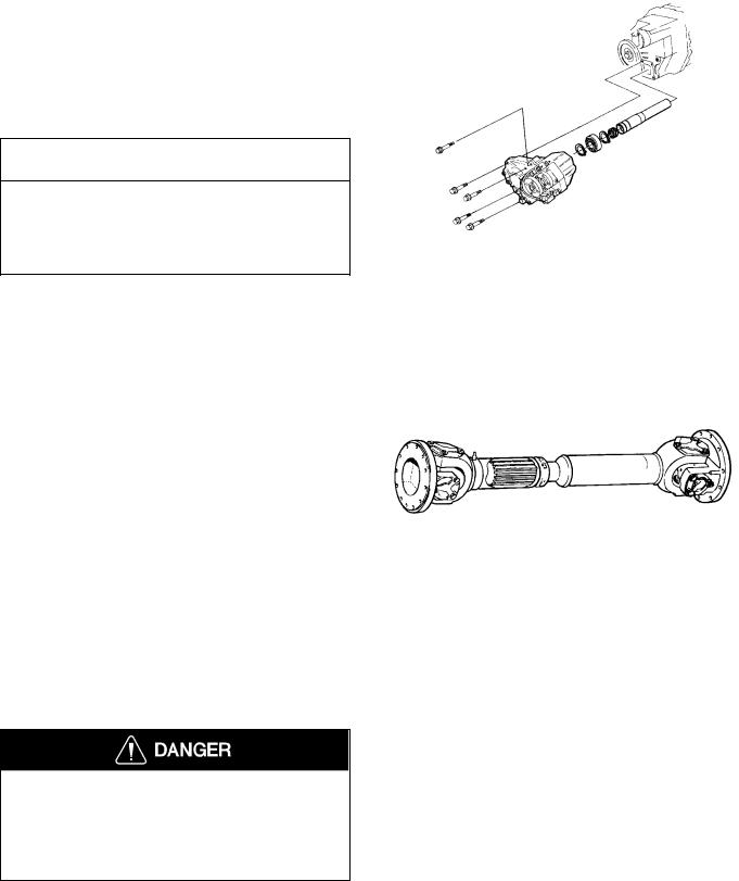
Driveshaft
For further information concerning component specifications see service information in Group 1, “Oil and Filter Change Intervals for Volvo Components,” publication number 175–001, and appropriate vendor literature.
Use a lithium-based grease with EP additives with a consistency of NLGI No. 2. Do not use conventional chassis grease.
The driveshaft U-joints must be lubricated correctly for the bearings to receive grease. The most common case of U-joint failure is incorrect greasing. Always make sure that grease is coming out of all four seals. If one seal fails to purge old grease, move the driveshaft from side to side while applying gun pressure. This allows for greater clearance on the thrust end of the bearing that is not purging. New grease flushes abrasive contaminants from each bearing and assures that the bearing is filled properly.
Failure to correctly grease the driveshaft U-joints or slip-joints can lead to component failure which can result in separation of the driveshaft from the vehicle. A separated driveshaft can result in major component damage and loss of vehicle control, and can cause serious personal injury or death.
25

Group 177 |
Design and Function |
Brakes
Brake Cams and Slack Adjusters
For further information concerning component specifications see service information in Group 1, “Oil and Filter Change Intervals for Volvo Components,” publication number 175–001, and appropriate vendor literature.
Lubricate the brake cam bushings using a lithium based grease with EP additives and consistency NLGI No. 2. Fill grease until old grease has been pushed out past the seal and new grease can be seen flowing.
Lubricate the slack adjusters using a lithium based grease with EP additives and consistency NLGI No. 2. Fill grease until old grease has been pushed out past the splined shaft area, and adjustment pawl and new grease can be seen flowing.
Air Dryers
Air dryers have internal maintenance systems that clean out the accumulated moisture frequently and can therefore work with long maintenance intervals. Eventually the drying medium will be filled up and the cartridge will need to be changed. Change cartridge when there is more water being drained in the daily emptying of the tank than usual. This is a progressive development and the time interval will be different from application to application.
Dryer manufacturers recommend changing cartridge every 2 to 3 years but intervals need to be adjusted for application. The only dryer with regular maintenance is the Midland, where the coalescent filter needs changing every year.
26

Group 177 |
Design and Function |
Steering System
Steering Linkage and Knuckles
For further information concerning component specifications see service information in Group 1, “Oil and Filter Change Intervals for Volvo Components,” publication number 175–001, and appropriate vendor literature.
Lubricate the Steering shaft and drag link.
Lubricated the tie rod.
TRW steering gears have a seal at the sector shaft that needs greasing with a hand gun every 4 months or more often if the weather and road conditions are severe.
Sheppard steering gears have seals at input shaft and at the sector shaft that need greasing with a hand gun every 4 months or more often if the weather and road conditions are severe.
No axial movement is allowable when 100 lbs. of hand pressure is applied. Use hand pressure only, do not check using pliers, wrenches or any other tools.
For all VHD Axle Back models, the steering shaft U- joints should be inspected to see that the plastic caps are intact. Complete this inspection every 4 months. A shorter inspection period interval may be required if the vehicle is operated under severe driving conditions.
For VHD Axle Forward models, grease the steering shaft U-joints every 4 months. A shorter maintenance interval may be required if the vehicle is operated under severe driving conditions.
27
Group 177 |
Design and Function |
Steering System
For further information concerning component specifications see service information in Group 1, “Oil and Filter Change Intervals for Volvo Components,” publication number 175–001, and appropriate vendor literature.
A darkened fluid indicates a steering system that is running hotter than normal and the fluid is overheated. Troubleshoot the reason for overheating and change fluid.
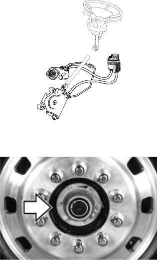
Hubs
Oil Lubricated Hubs
For further information concerning component specifications see service information in Group 1, “Oil and Filter Change Intervals for Volvo Components,” publication number 175–001, and appropriate vendor literature.
Hubs are generally oil lubricated and should be lubricated during maintenance. Change oil when the hub is removed for repairs.
28
 Loading...