

Page 1
Service Training
Self-study programme 338
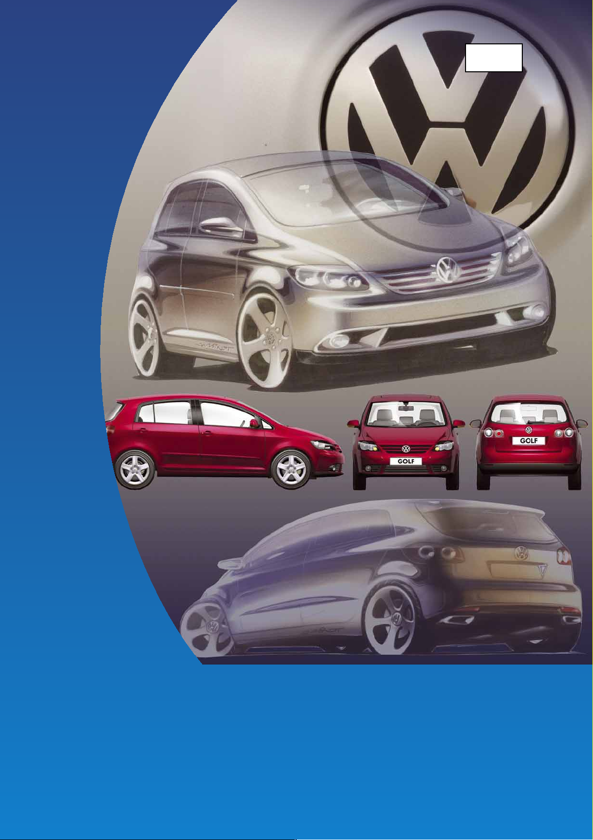
The Golf Plus 2005
Page 2
The Golf Plus is based on the Golf's successful history
as the benchmark in the compact class, is positioned
in the new segment of high-roof passenger cars and
can therefore safely claim leadership in the Golf
segment.
It is intended to continue to the "superior dynamics"
positioning introduced by the Golf in 2004, extending
this with characteristics such as spatial comfort,
variability and functionality.
This self-study programme provides an overview of the structure of the Golf Plus.
It informs you of the special body features, which engines and gearboxes are installed,
which front and rear axles carry the Golf, how the electronics are structured and what changes have taken place in
the convenience system.
NEW Attention
The self-study programme portrays the design and
function of new developments!
The contents will not be updated.
For current testing, adjustment and repair instructions, please refer to the customer service literature
intended for this purpose.
S338_105
Note
2
Page 3

At a glance
In brief . . . . . . . . . . . . . . . . . . . . . . . . . . . . . . . . . . . . . . . . . . . . . . . . . . . . . . . 4
Body . . . . . . . . . . . . . . . . . . . . . . . . . . . . . . . . . . . . . . . . . . . . . . . . . . . . . . . . 8
Occupant protection . . . . . . . . . . . . . . . . . . . . . . . . . . . . . . . . . . . . . . . . . . 18
Engine-gearbox combinations . . . . . . . . . . . . . . . . . . . . . . . . . . . . . . . . . . 20
Engines . . . . . . . . . . . . . . . . . . . . . . . . . . . . . . . . . . . . . . . . . . . . . . . . . . . . . 22
Power transmission . . . . . . . . . . . . . . . . . . . . . . . . . . . . . . . . . . . . . . . . . . . 26
Running gear . . . . . . . . . . . . . . . . . . . . . . . . . . . . . . . . . . . . . . . . . . . . . . . . 28
Electrical system . . . . . . . . . . . . . . . . . . . . . . . . . . . . . . . . . . . . . . . . . . . . . . 30
Convenience electronics . . . . . . . . . . . . . . . . . . . . . . . . . . . . . . . . . . . . . . . 38
Radio and navigation . . . . . . . . . . . . . . . . . . . . . . . . . . . . . . . . . . . . . . . . . 44
Heater and air conditioner . . . . . . . . . . . . . . . . . . . . . . . . . . . . . . . . . . . . . 48
Service . . . . . . . . . . . . . . . . . . . . . . . . . . . . . . . . . . . . . . . . . . . . . . . . . . . . . 55
3
Page 4
In brief
The Golf Plus 2005
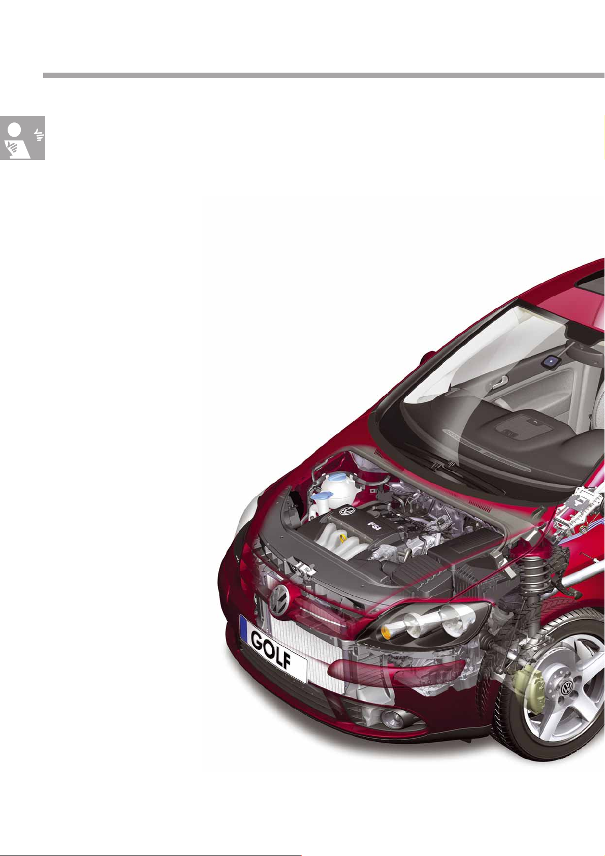
In addition to the technology familiar from the Golf,
the Golf Plus is equipped with a few further special
features.
This includes its higher body, its rear lights in LED
technology and also its split rear seat bench, which
can be separately adjusted and
moved.
● Sensor for rain and light detection
● Extensive storage compartment concept
● 2C-Climatronic
(2-zone climate control)
● Modified bonnet
Front area optimised to protect pedestrians
● Headlights in
bi-xenon technology with
cornering light function
● New headlights with three round elements
4
Page 5
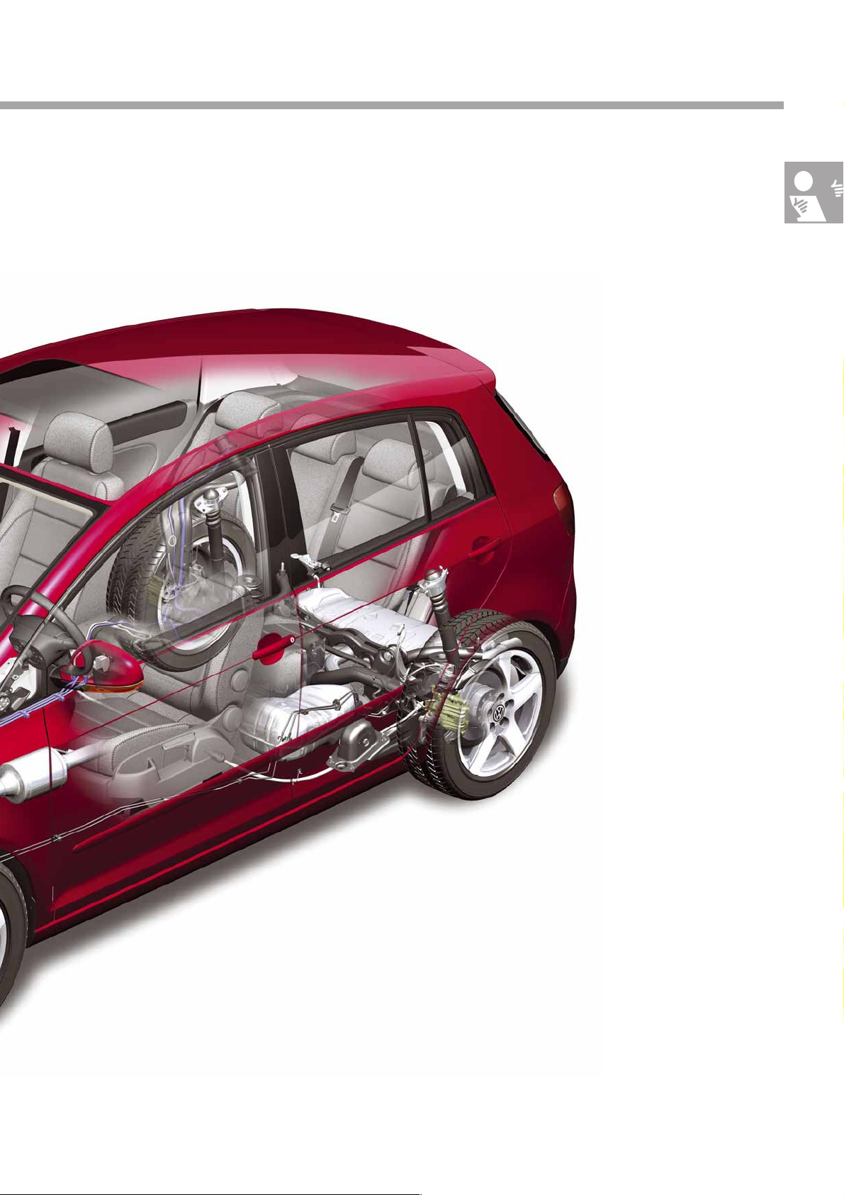
● Rear Seat Entertainment system
● 230V socket
● Body 95mm higher
● Rear lights
in LED technology
● Variable
load floor concept
● Split rear seat bench,
● Seating level 80mm higher
S338_001
can be separately moved and adjusted
5
Page 6
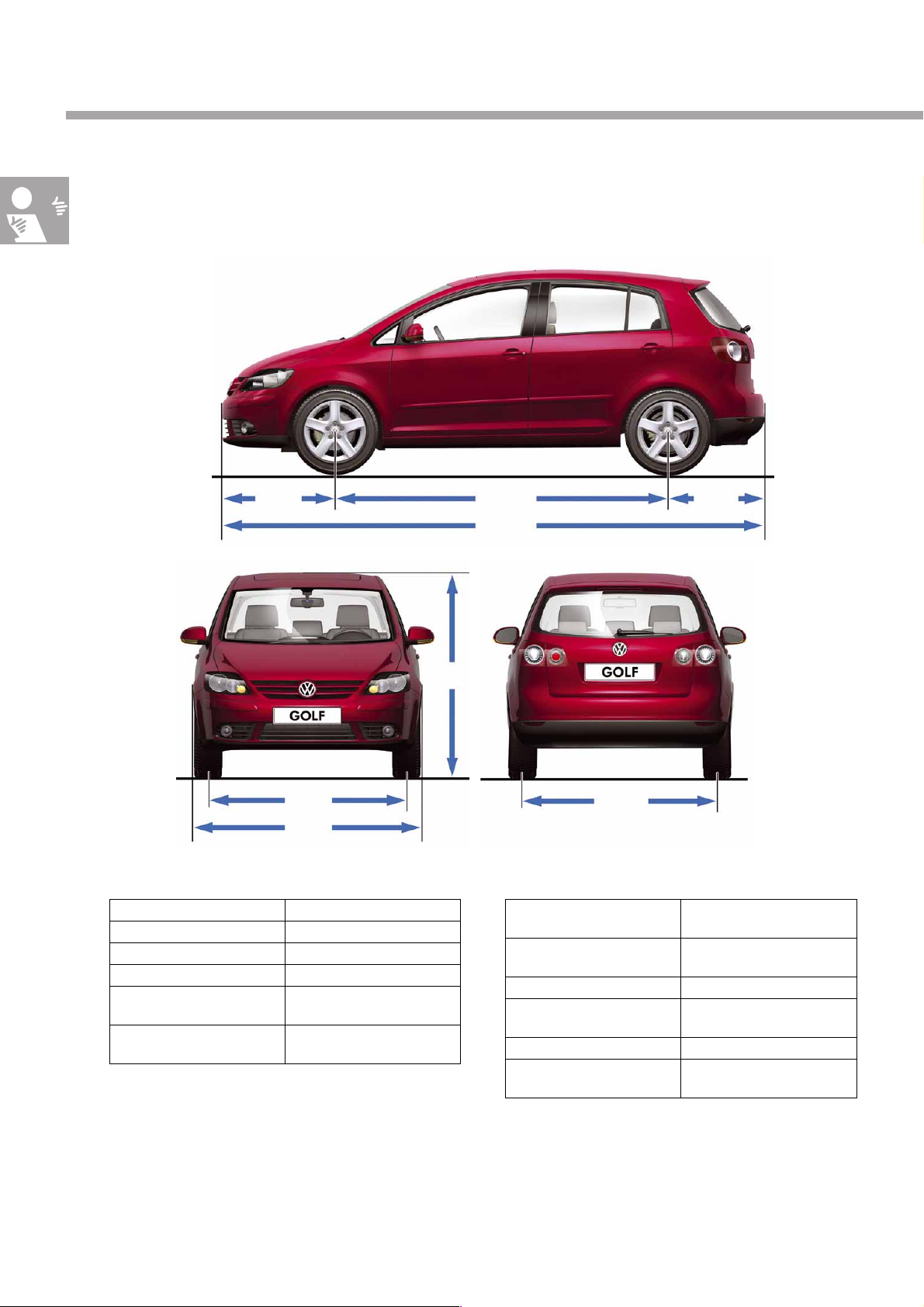
In brief
Technical data
Exterior dimensions and weights
877mm 2578mm 751mm
S338_052
4206mm
1541mm
1759mm
Exterior dimensions
Length 4206 mm
Width 1759mm
Height 1580mm
Wheelbase 2578mm
Front track 1541mm
Rear track 1529mm
1580mm
S338_051
1529mm
S338_053
Weights
Permissible gross vehicle
weight
Unladen weight without
driver
Roof load 75kg
Trailed load (braked) 1200kg at 8% incline
Fuel tank capacity 55l
Drag coefficient 0.32
1900kg
1293kg
6
Page 7
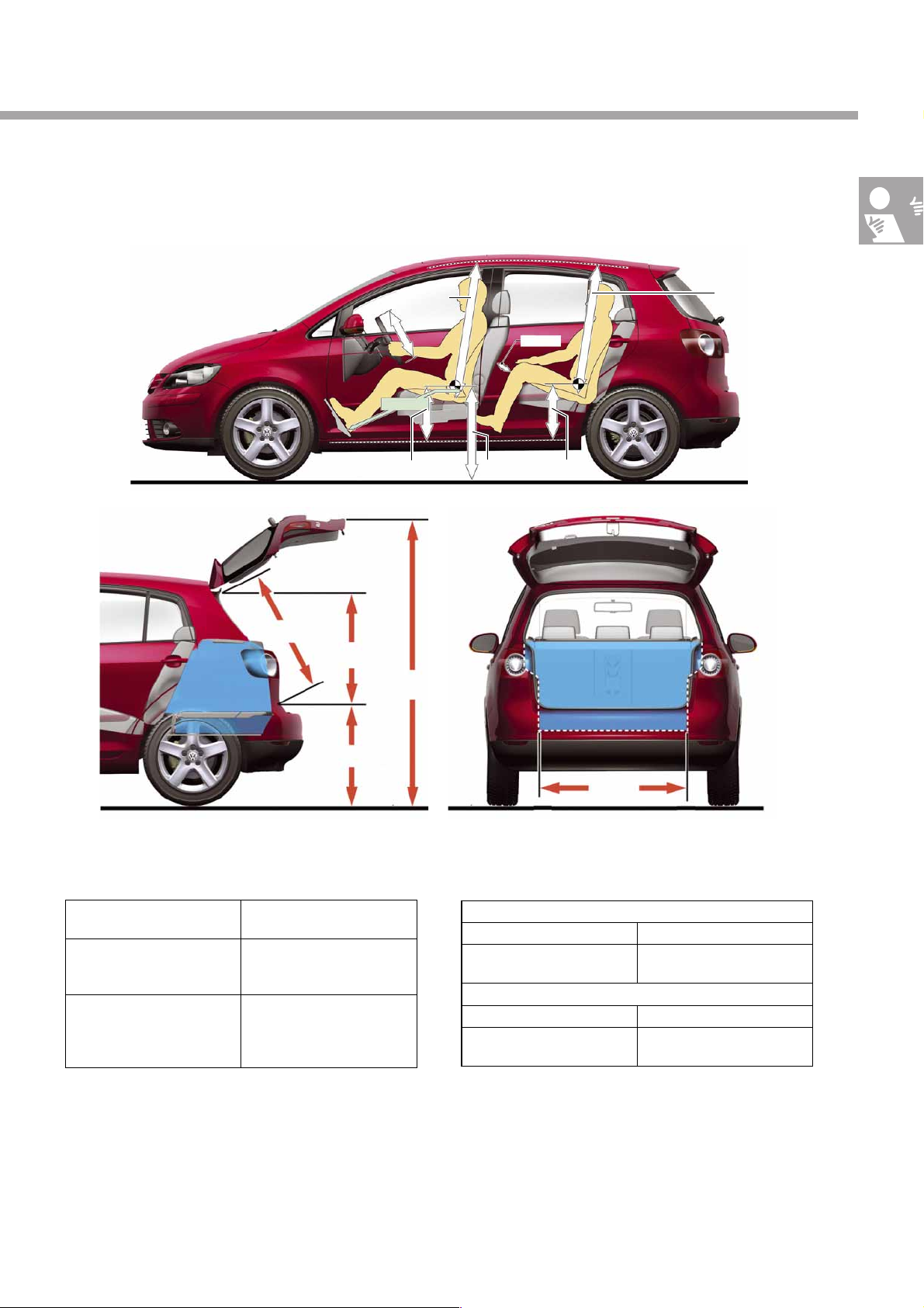
Interior dimensions
842mm
750 mm
1007mm
375mm
1019mm
343mm
2076mm
585mm
976mm
70mm
375mm
S338_054
Interior dimensions and volumes
Total interior length 1740mm
Luggage compartment
volume
Luggage compartment
volume with rear seat backrest folded down
* - Without variable load floor
** - With variable load floor
425 - 505l *
402 - 443l **
1450l *
1350l **
624mm
S338_055
1008mm
S338_056
Interior dimensions, front
Headroom 1007mm
Elbow width 1468mm
Interior dimensions, rear
Headroom 976mm
Elbow width 1452mm
7
Page 8
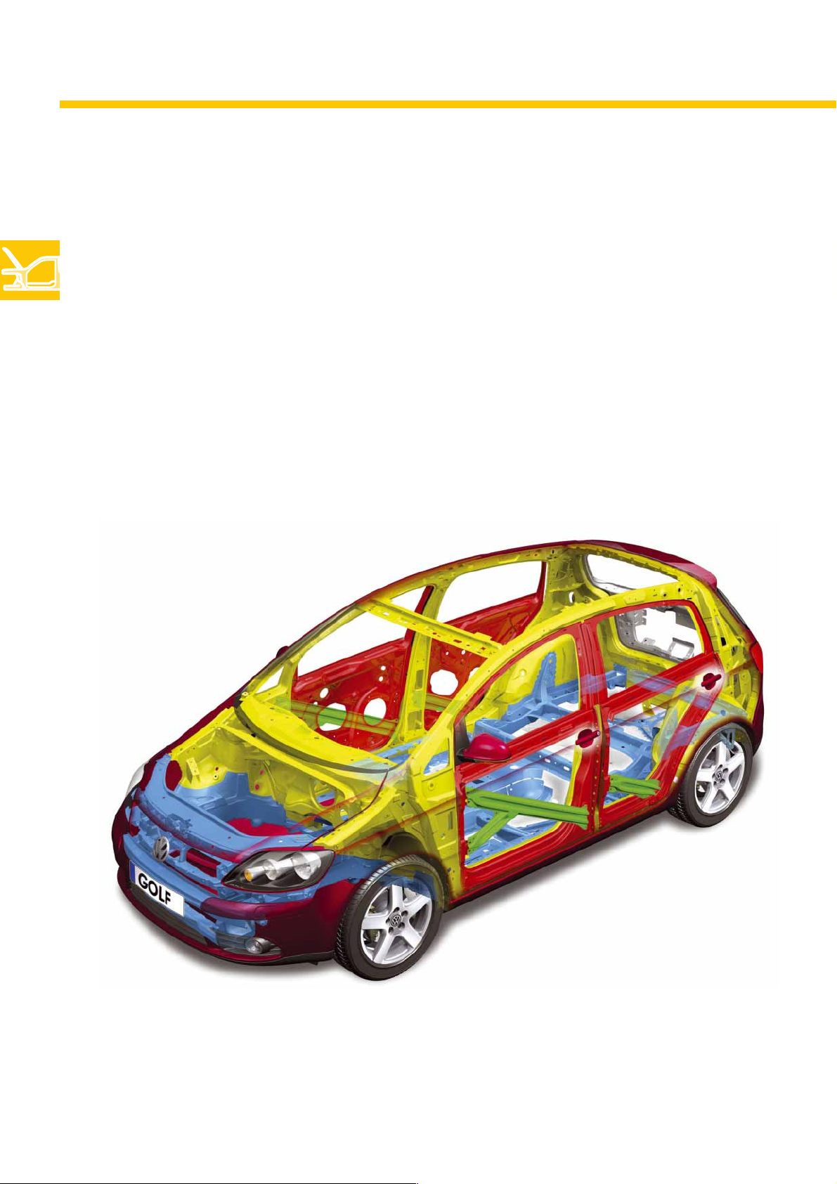
Body
The body structure
Its concept has been integrated from the tried-and-tested Golf 2004 and adapted to the requirements of the
Golf Plus.
By consistently employing high- and ultra-high-strength panels, its strength has again been
optimised without significantly increasing its weight.
Special characteristics
● The A-pillar has been modified to integrate
the quarter light.
● The roof bow has been omitted thanks to the
design of the side areas.
S338_023
8
Page 9
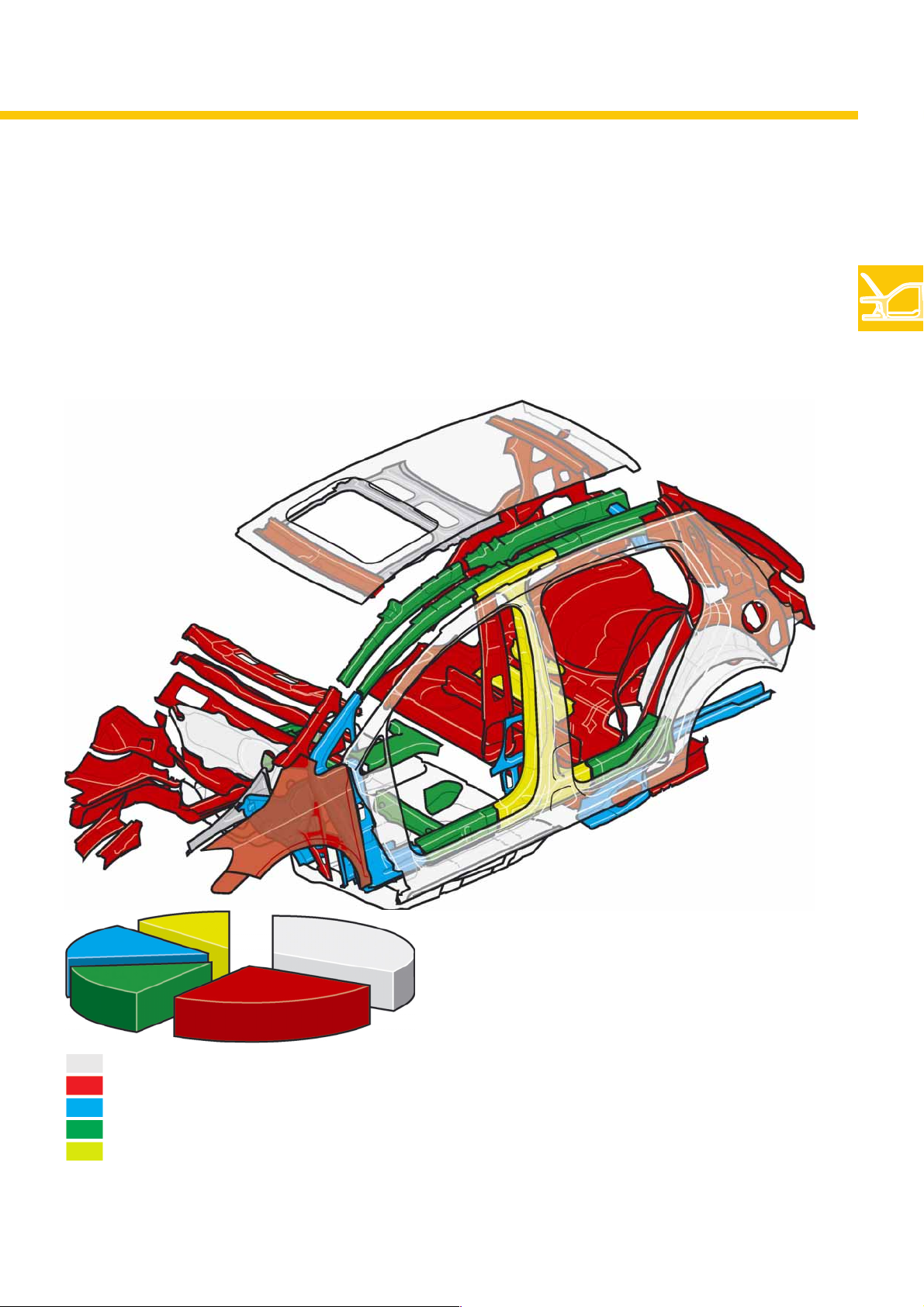
Steel grades in the Golf Plus
Steels are classified according to their tensile strength. The higher the steel grade, the higher the tensile strength,
which is measured in Megapascals. The higher material properties are achieved by alloying and hardening the
steel in different ways. The Golf Plus body is essentially comprised of five different steel grades.
S338_096
Normal plate grade up to 180 MPa
High-strength plate grade 220 - 240 MPa
Higher-strength plate grade 280 -300 MPa
Ultra-high-strength plate grade 320 -420 MPa
Ultra-high-strength, treated plate grade over 900 MPa
1 MPa = 1 Newton/mm
The specified values refer to the yield strength.
2
S338_119
Even this limited selection of body-inwhite parts shows the considerable
percentage of higher-strength panels
in the Golf Plus.
9
Page 10
Body
The storage compartments
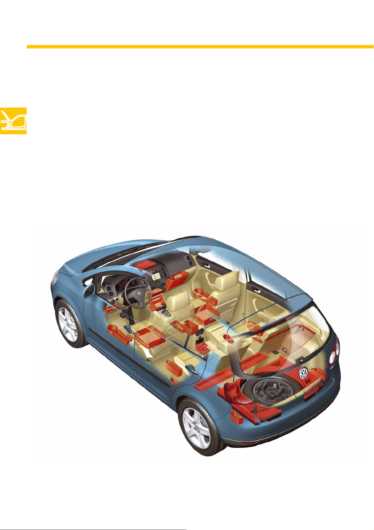
Besides a multitude of storage compartments familiar from the Golf 2004, the Golf Plus additionally offers storage
compartments in the centre console and drawers beneath the front seats.
In vehicles fitted with the Rear Seat Entertainment system, the DVD player is located in the storage compartment
between the front seats beneath the armrest.
10
S338_057
Page 11
The roof console
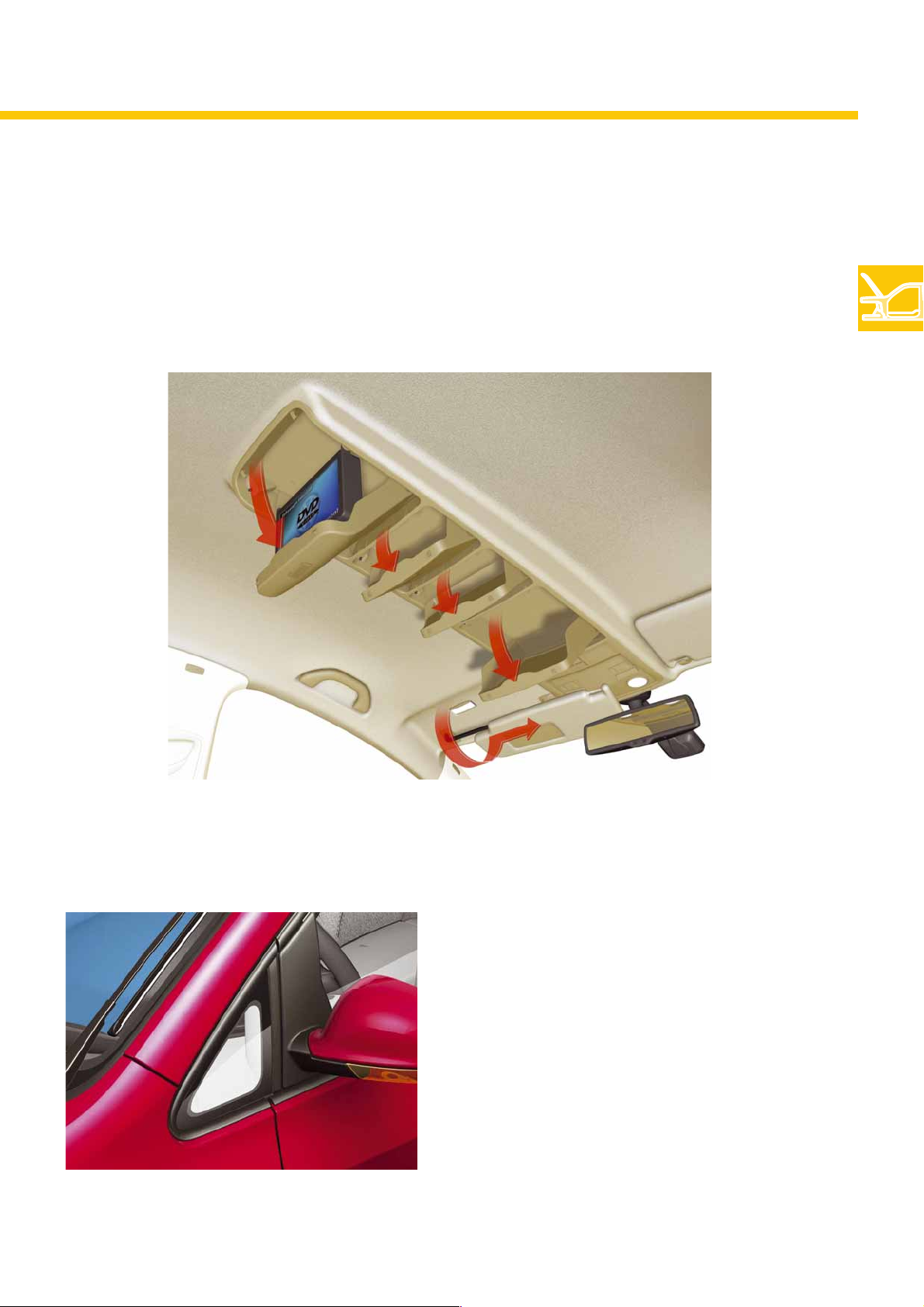
The Golf Plus is optionally available with a large roof console.
Three unfolding storage compartments are located in the front area. The rear area houses the fold-down monitor in
vehicles fitted with the Rear Seat Entertainment system.
Glazing
S338_027
The quarter light is bonded-in.
S338_071
11
Page 12
Body
The load floor
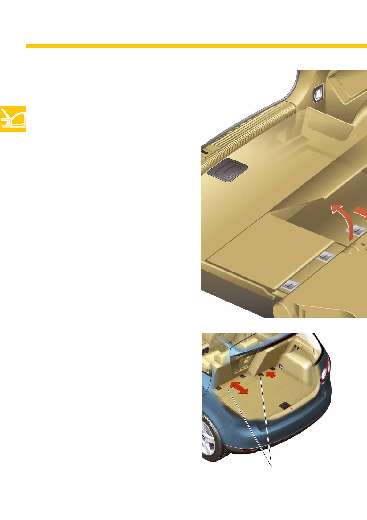
The Golf Plus has a variable load floor.
This means:
● The load floor is height-adjustable.
● The load floor can be removed.
● The length of the load floor adapts to the
longitudinally-adjustable rear seat bench.
12
Longitudinal adjustment
This is carried out by means of movable covers, which
are locked along with the rear seats. When the rear
seats are moved, the covers therefore move back and
forth together with the seats. The covers slide beneath
the load floor in this case.
S338_058
Sliding covers
Page 13
Height adjustment
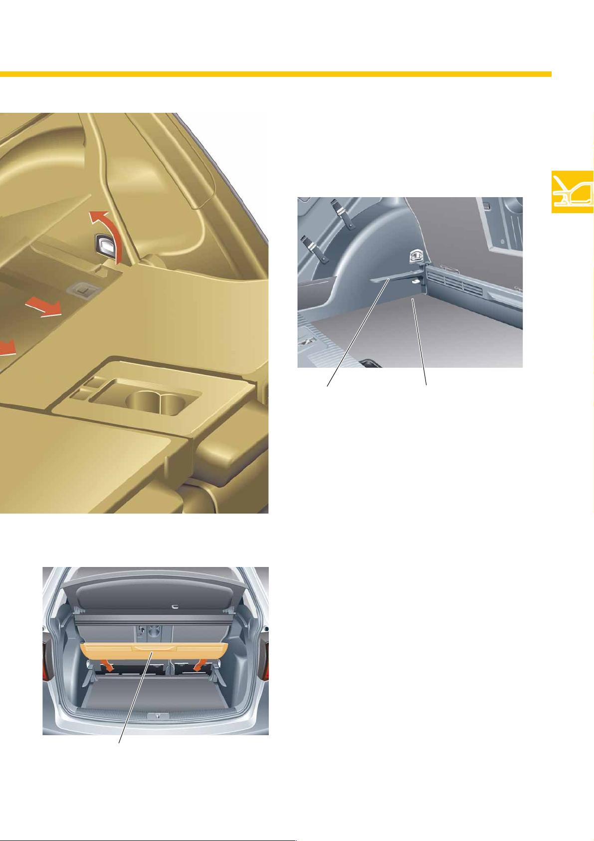
The load floor can be inserted at two heights.
Top insertion option Bottom insertion option
S338_106
Transverse rail
S338_029
Removing the load floor
In addition to the load floor, the transverse rail can
also be removed. This results in maximum luggage
compartment volume.
S338_122
13
Page 14
Body
The seats
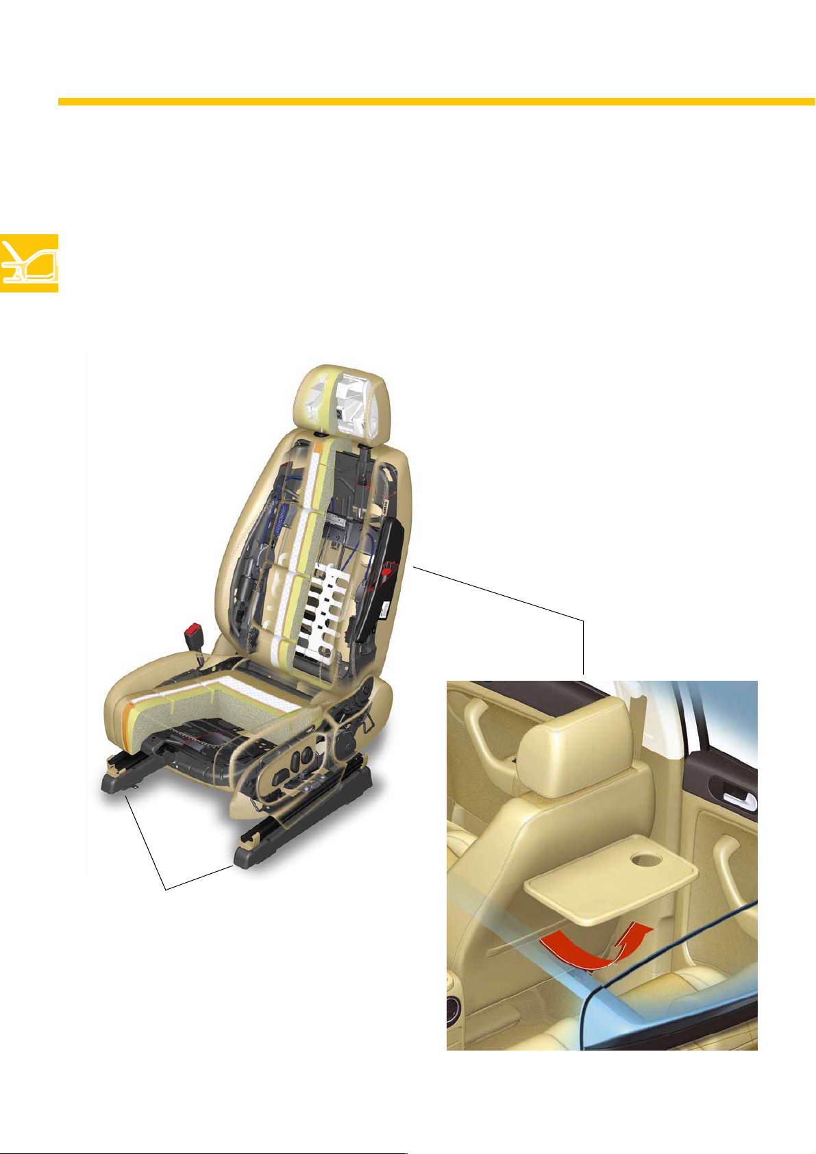
The front seats
The seat frames have been integrated from the Golf 2004.
The higher fastening bracket results in a seating position which is higher than that in the Golf 2004.
A front passenger seat with the through-loading option familiar from the Golf 2004 is also available as an
optional extra.
14
S338_135
Fastening bracket
The rear side of the seat backrests are fitted with
folding tables for the rear passengers.
S338_072
Page 15
The rear seat bench
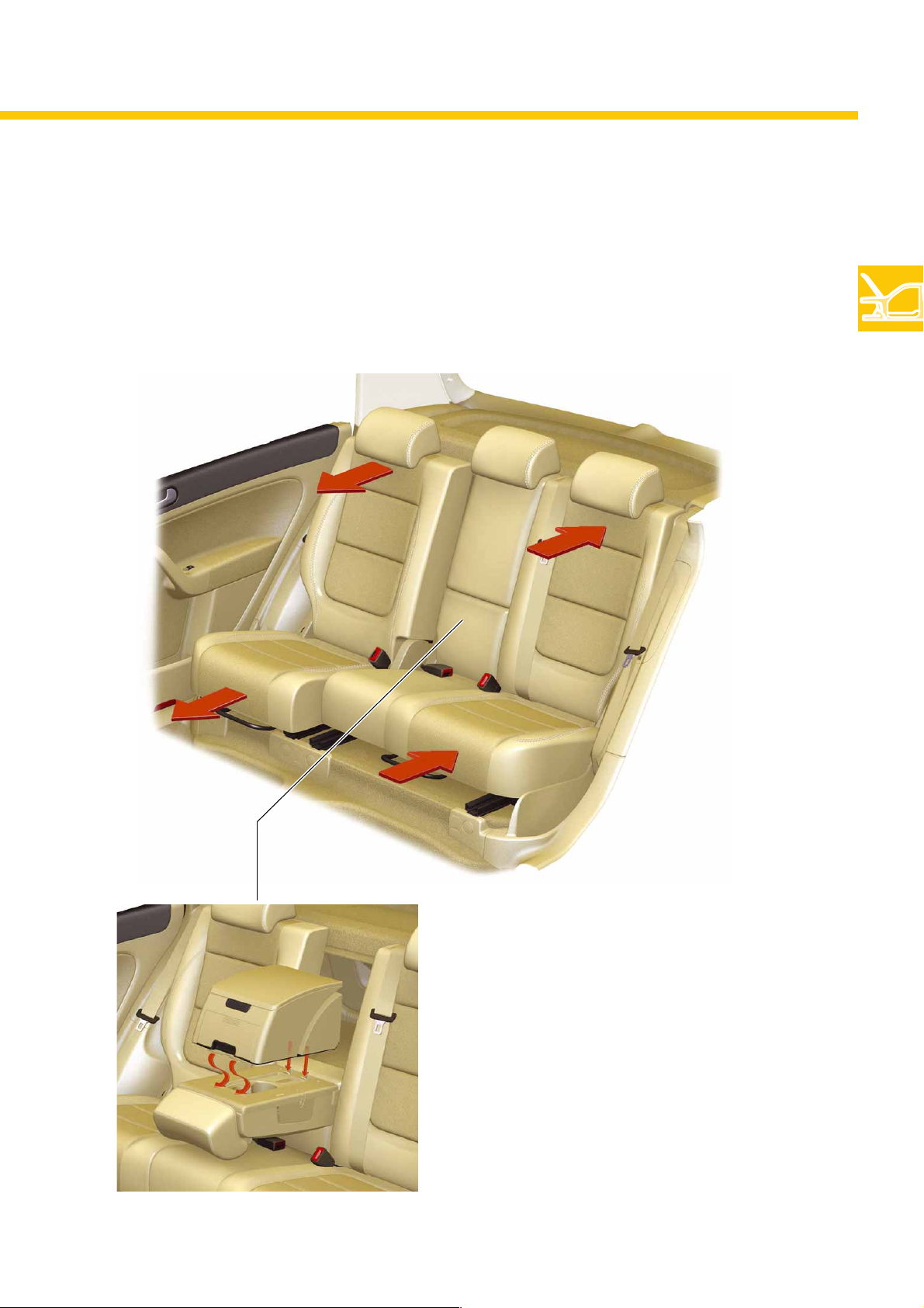
This is split into two. Both sections can be individually moved 160mm in the longitudinal direction.
By pulling on the release straps, the inclination of these can be adjusted, the sections can be completely folded.
S338_074
S338_073
As an additional storage option, a multi-function box
can be secured to the folding centre armrest.
15
Page 16
Body
Pedestrian protection
The bumper
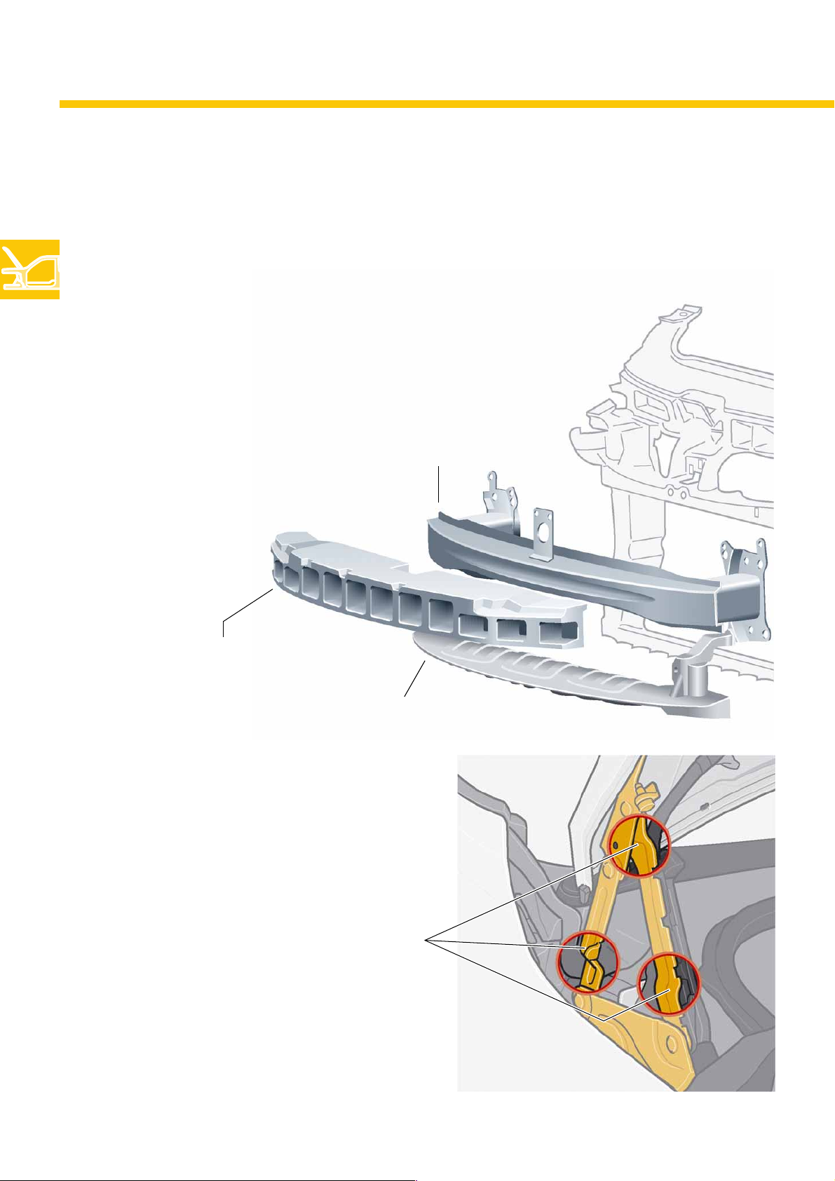
To reduce the risk of injury to pedestrians, the bumper cross-member is
covered with a foam part.
The pedestrian protection cross-member is located beneath the bumper
cross-member.
This reduces the risk of injury to pedestrians' legs.
Bumper cross-member
Foam
Pedestrian protection
cross-member
The bonnet hinge
To ensure that the bonnet also yields in the hinge area
in the event of an impact involving a pedestrian,
the hinges have also been provided with nominal
bending points.
Nominal bending points
S338_108
16
S338_118
Page 17
The bonnet support
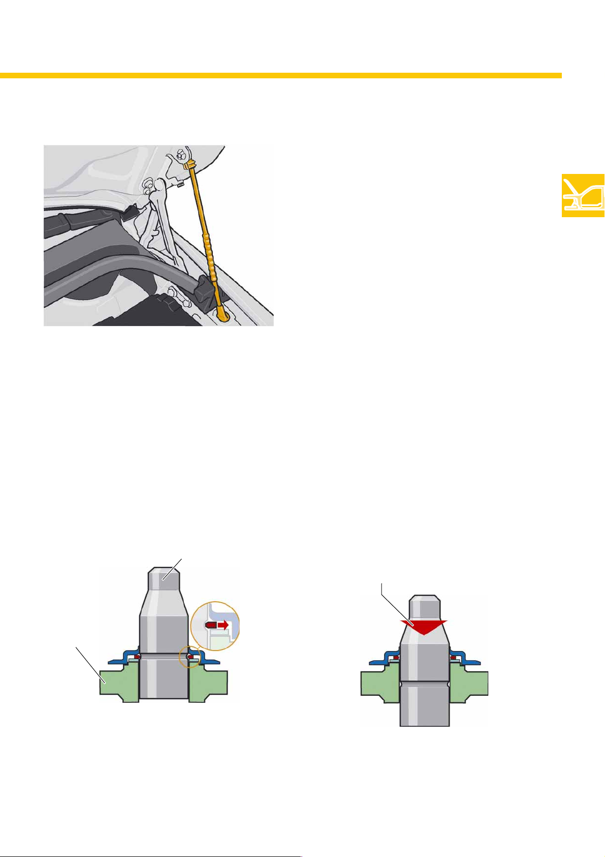
The windscreen wiper shafts
This area has also been optimised for pedestrian
protection by using a bonnet support instead of a gas
pressure spring.
In contrast to a gas pressure spring, the bonnet
support is able to bend in the event of an impact.
S338_117
The wiper shafts have also been revised to enhance pedestrian protection.
In the event of an impact, the shafts slide into the mounting bracket and thereby reduce the risk of injury
to the pedestrian.
Operating position
Wiper shaft
Mounting bracket
S338_097
Situation following impact
Wiper shaft slides into
the mounting bracket
S338_098
17
Page 18
Occupant protection
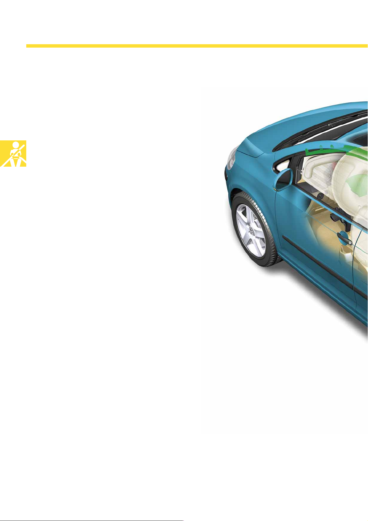
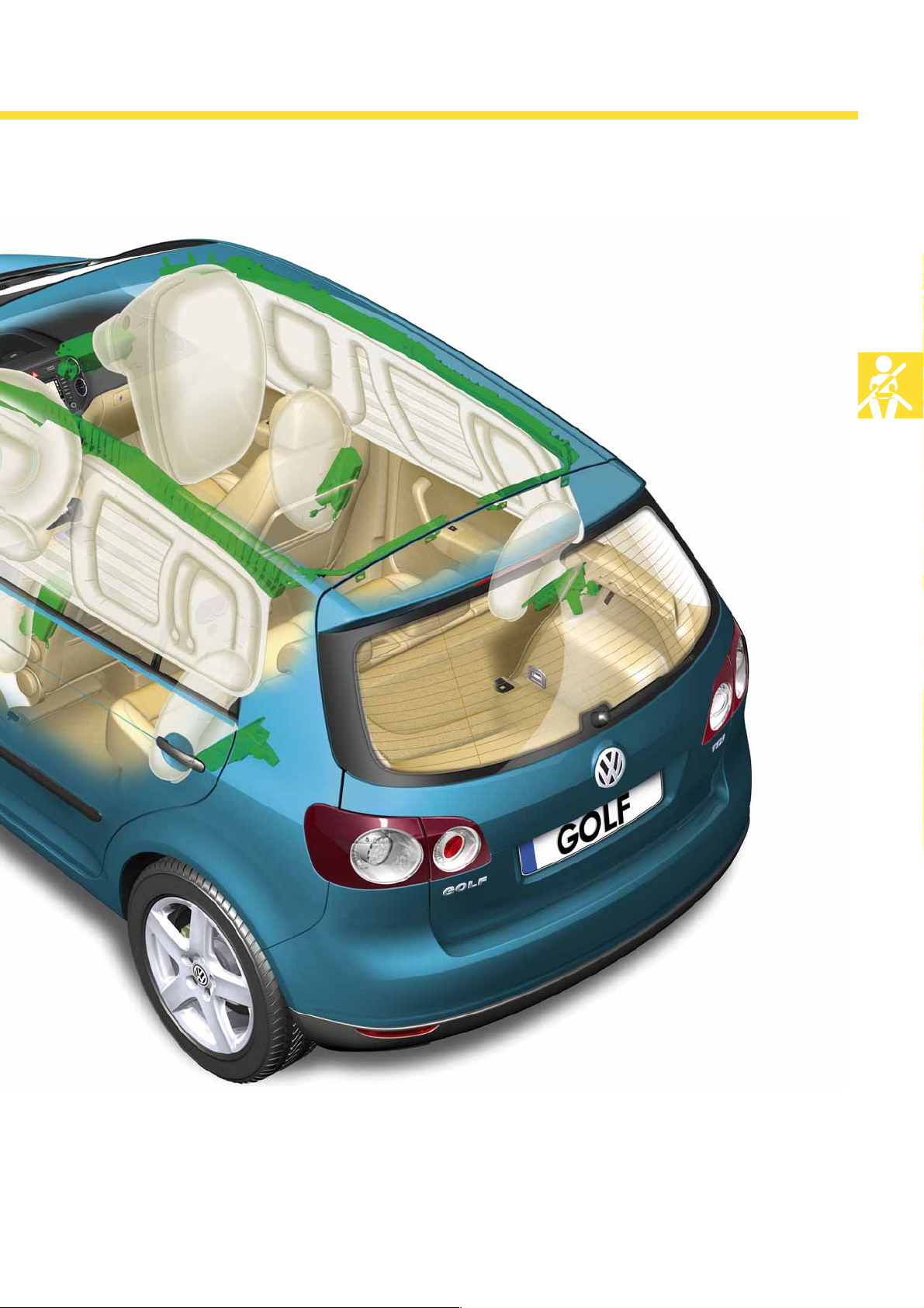
The airbags
The airbag system familiar from the Golf 2004 is also
fitted in the Golf Plus:
● Driver and front passenger airbag
● Side airbag in the front seats
● Head airbag for the front and rear
passengers
● 3-point seat belts on all seats
● Seat belt pretensioner, belt tension limiter and seat
occupied sensor for the front passengers.
● Active headrests on the front seats
● Seat belt prompt for the driver and front passenger
● Optional rear side airbag in the wheel housing trim
in combination with rear seat belt pretensioner
18
The following crash sensors, which are already
familiar from the Golf, are installed:
● Pressure sensors in the front doors
● Acceleration sensors in the area of the rear
wheel housing
Page 19
S338_067
19
Page 20
Engines
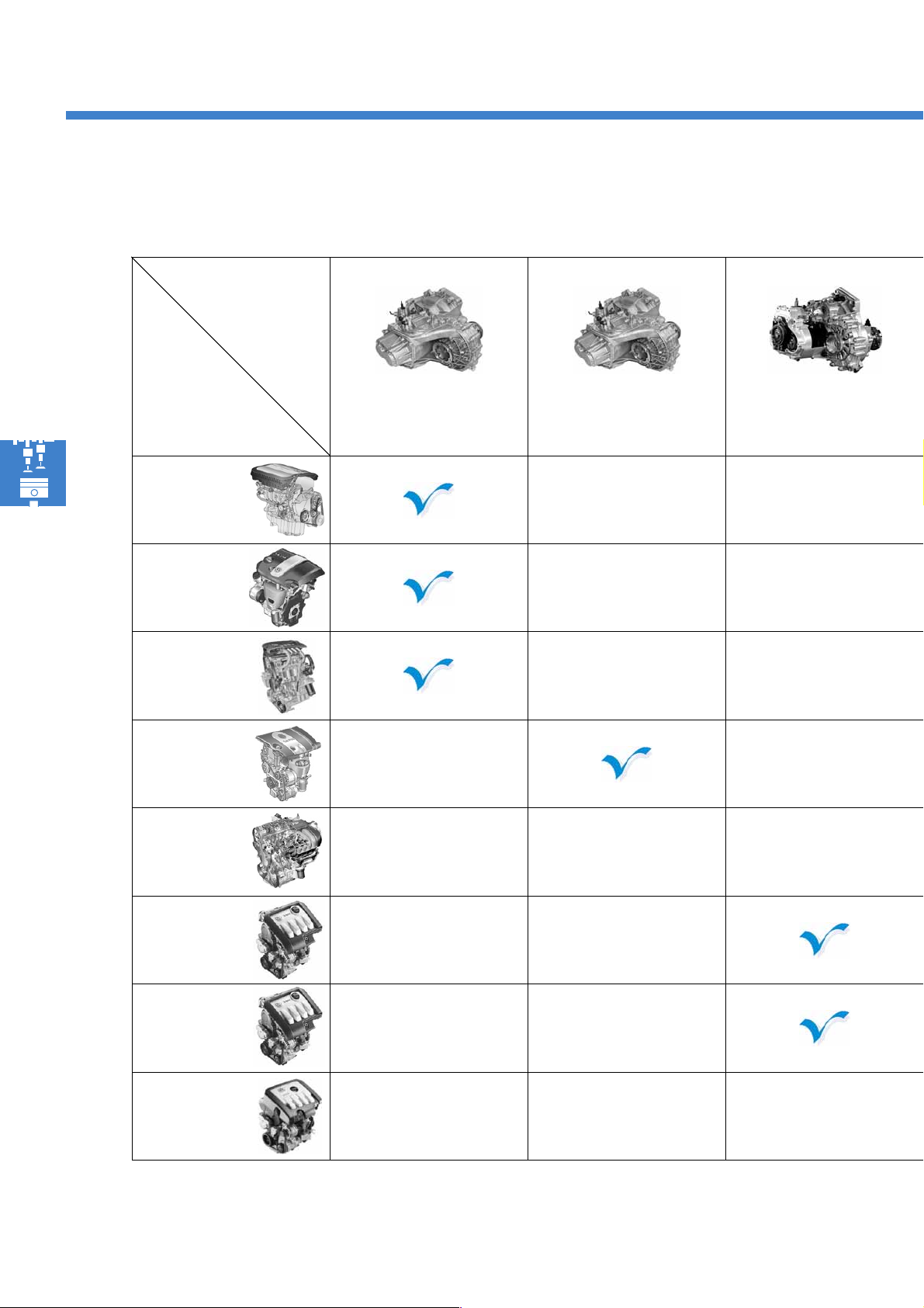
Engine-gearbox combinations
Gearbox
Engine
1.4l 55 kW
SRE engine
1.4l 66 kW
FSI engine *
1.6l 75 kW
engine *
1.6l 85 kW
FSI engine
2.0l 110 kW
FSI engine *
0AF: 5-speed
manual
gearbox
0AG: 6-speed
manual
gearbox
0A4: 5-speed
manual
gearbox
20
1.9l 66 kW
TDI engine *
1.9l 77 kW
TDI engine
2.0l 103 kW
TDI engine
The engines and gearboxes marked with a * will be launched at a later point in time.
Page 21
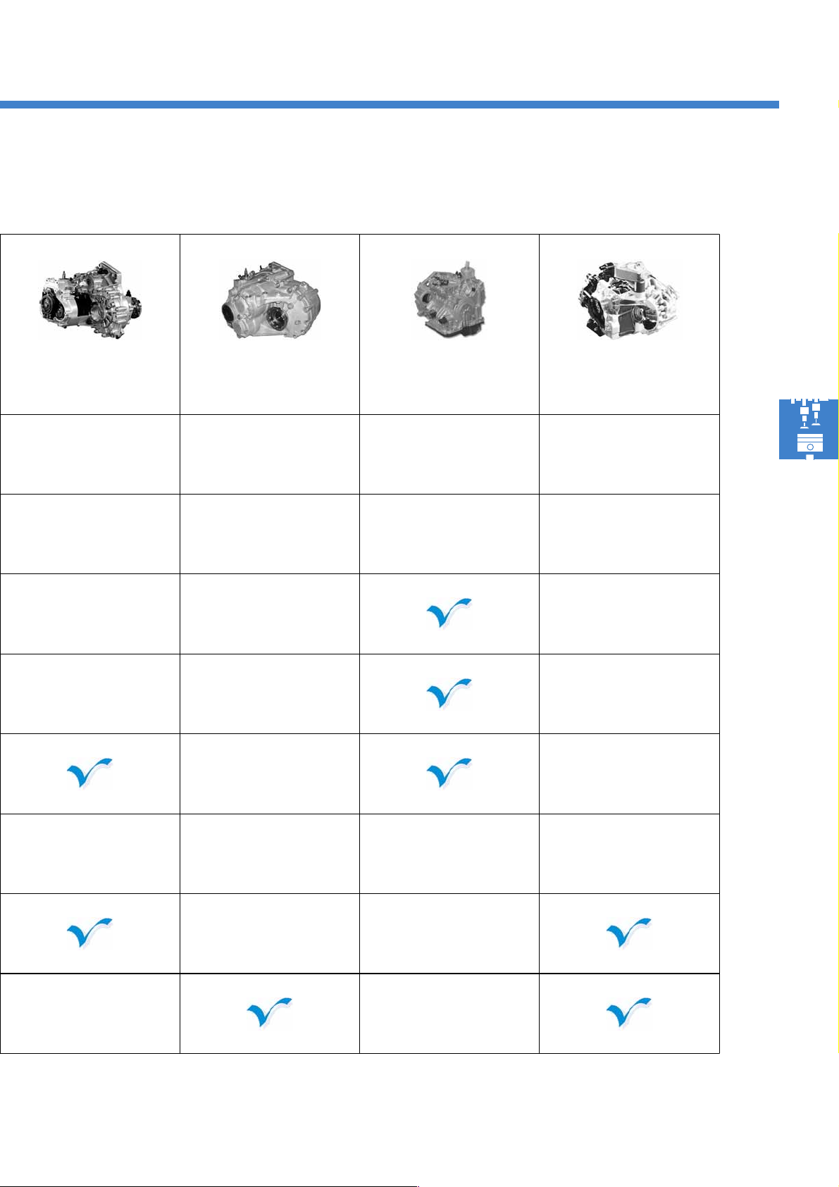
02S: 6-speed
manual
gearbox
02Q: 6-speed
manual
gearbox
09G: 6-speed
automatic
gearbox
DSG 02E: 6-speed
Direct-
Shift Gearbox*
21
Page 22
Engines
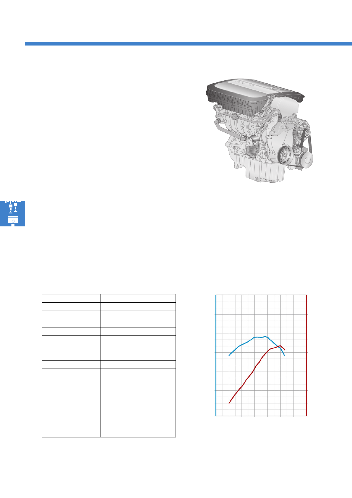
The 1.4l 55 kW engine
The 1.4l 55 kW engine is the entry-level engine for the
Golf Plus. This has been taken over from the Golf
2004 and adapted to the package conditions in the
Golf Plus.
Special characteristics
● Return-free fuel system
● Crankshaft sealing flange with magnetised sender
wheel for engine speed
● Accelerator pedal module with contact-free
accelerator pedal position sender
● Clutch module with contact-free clutch position
sender
● Throttle valve control unit with contact-free throttle
valve position angle senders
● Primary catalytic converter with ceramic substrate
and reduced precious metal charge
● Main catalytic converter with reduced precious
metal charge
S338_014
Technical data
Engine code BCA
Design type 4-cylinder in-line engine
Displacement [cm³] 1390
Bore [mm] 76.5
Stroke [mm] 75.6
Valves per cylinder 4
Compression ratio 10.5:1
Max. output 55kW at 5000 rpm
Max. torque 126 Nm at 3800 rpm
Engine management
system
Fuel Super unleaded RON 95
Exhaust gas aftertreatment Primary catalytic converter, main
Exhaust emission standard EU4
Bosch Motronic ME 7.5.10
Normal unleaded RON 91
(with slightly reduced output)
catalytic converter, lambda control
Torque and output graph
180
160
140
120
100
80
Torque [Nm]
60
40
20
2000 4000 6000
Engine speed [rpm]
90
80
70
60
50
40
30
20
10
S338_015
Output [kW]
22
Page 23
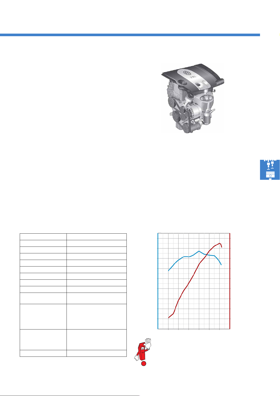
The 1.6l 85 kW FSI engine
This engine originates from the Golf 2004.
It differs from this only due to its switch to lambda 1
operation and super unleaded RON 95.
Special characteristics
Stratified charge and homogeneous lean operation
have been omitted due to the switch to lambda 1
(homogeneous operation). This leads to the
occurrence of less nitrogen oxide, and the omission of
complex trapping and regeneration of this.
S338_016
This leads to the following changes:
- The exhaust gas temperature sender has been
omitted,
- instead of the NO
storage reduction catalytic
x
converter, a
three-way catalytic converter has been installed,
and
- instead of the NO
sender, a transient
x
lambda probe has been installed.
Technical dat a
Engine code BLF
Design type 4-cylinder in-line engine
Displacement [cm³] 1598
Bore [mm] 76.5
Stroke [mm] 86.9
Valves per cylinder 4
Compression ratio 12:1
Max. output 85kW at 6000 rpm
Max. torque 155 Nm at 4000 rpm
Engine management
system
Fuel Super unleaded with RON 95
Bosch Motronic MED 9.5.10
(super plus RON 98 leads to an
increase in torque in the medium
engine speed range)
The switch from super plus RON 98 to super unleaded
RON 95 is achieved via ignition angle adjustment.
Operation with RON 91 is not permitted,
as ignition is retarded to the control limits in this case.
Torque and output graph
Torque [Nm]
180
160
140
120
100
80
60
40
20
90
80
70
60
50
40
30
20
10
Output [kW]
Exhaust gas aftertreatment Primary catalytic converter,
main catalytic converter, lambda
control
Exhaust emission standard EU4
2000 4000 6000
Engine speed [rpm]
Information on the fuel system can be found in selfstudy programme No. 334
"The FSI engine fuel system".
S338_017
23
Page 24
Engines
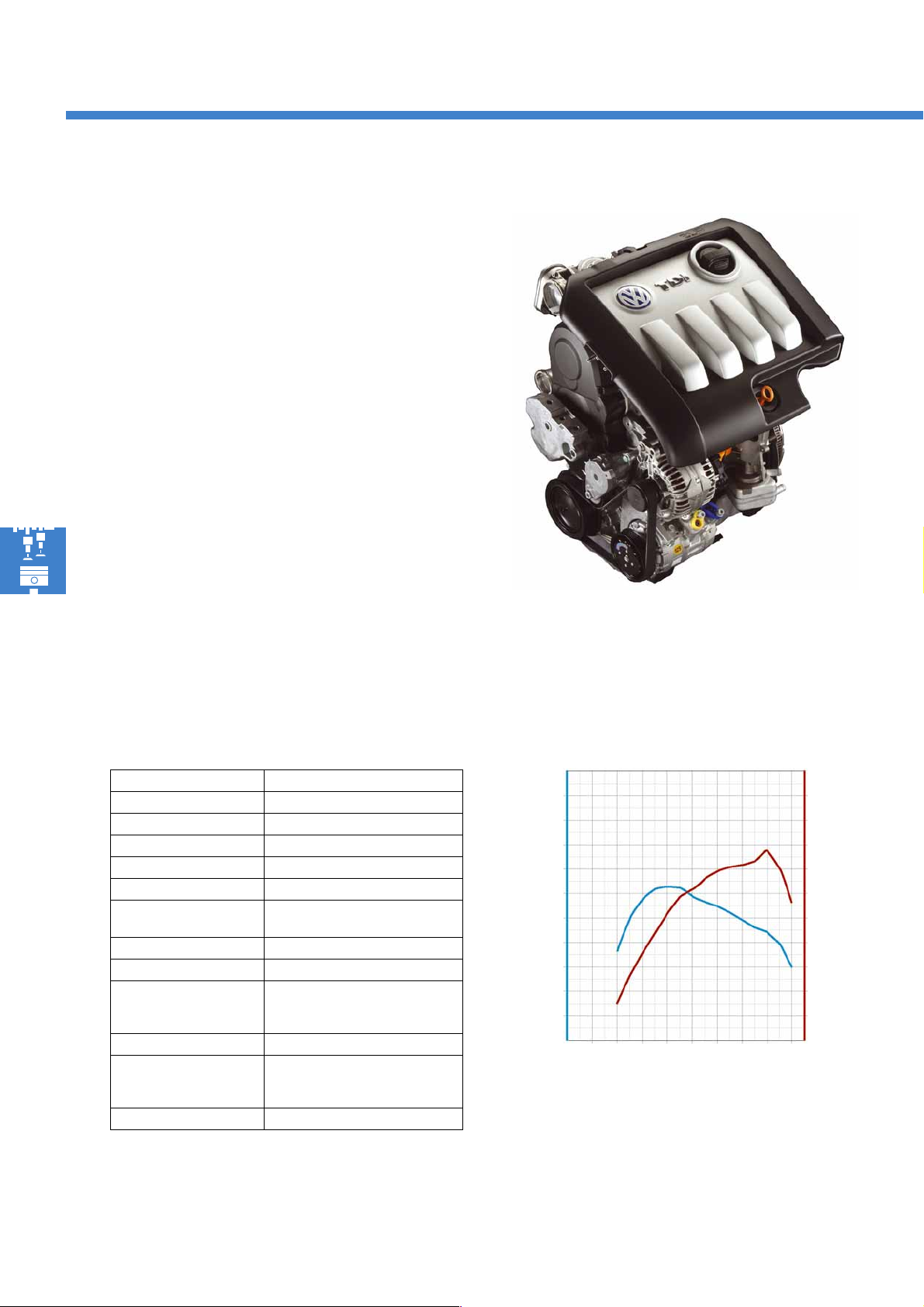
The 1.9l 77 kW TDI engine
This engine originates from the Golf 2004.
Special characteristics
● Switchable exhaust gas recirculation cooler,
● Crankshaft sealing flange with integrated
engine speed sender wheel,
● Accelerator pedal module with contact-free
accelerator pedal position senders,
● Contact-free clutch pedal switch.
S338_018
Technical data
Engine code BKC
Design type 4-cylinder in-line engine
3
Displacement [cm
Bore [mm] 79.5
Stroke [mm] 95.5
Valves per cylinder 2
Compression ratio 19:1
Max. output 77kW at 4000 rpm
Max. torque 250 Nm at 1900 rpm
Engine management
system
Fuel Diesel, at least 51 CN
Exhaust gas
aftertreatment
Exhaust emission standard EU4
]1896
Bosch EDC 16 with
unit injector system
Exhaust gas recirculation and
oxidising catalytic converter
Torque and output graph
400
320
240
Torque [Nm]
160
80
1000 2000 3000 4000
Engine speed [rpm]
100
80
60
Output [kW]
40
20
S338_020
24
Page 25
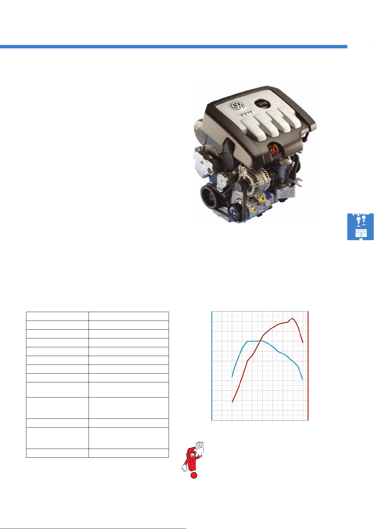
The 2.0l 103 kW TDI engine
This engine is identical to the 2.0l 103 kW TDI engine
fitted in the Golf 2004.
Special characteristics
● 4-valve technology,
● Two camshafts, driven by toothed
belts,
● New unit injectors which have been
adapted to the 4-valve technology,
● Switchable exhaust gas recirculation cooler,
● Crankshaft sealing flange with integrated
engine speed sender wheel,
● Accelerator pedal module with contact-free accele-
rator pedal position senders,
● Contact-free clutch pedal switch.
S338_019
Technical data
Engine code BKD
Design type 4-cylinder in-line engine
3
Displacement [cm
Bore [mm] 81
Stroke [mm] 95.5
Valves per cylinder 4
Compression ratio 18:1
Max. output 103kW at 4000 rpm
Max. torque 320 Nm at 1750 rpm
Engine management
system
Fuel Diesel, at least 51 CN
Exhaust gas
aftertreatment
Exhaust emission standard EU4
]1968
up to 2500 rpm
Bosch EDC 16 with
unit injector system
Exhaust gas recirculation and
oxidising catalytic converter
Torque and output graph
400
320
240
Torque [Nm]
160
80
0
1000 2000 3000 4000
Engine speed [rpm]
Further information on this engine
can be found in self-study programme No.
316 "The 2.0l TDI engine".
100
80
60
40
20
S338_021
Output [kW]
25
Page 26
Power transmission
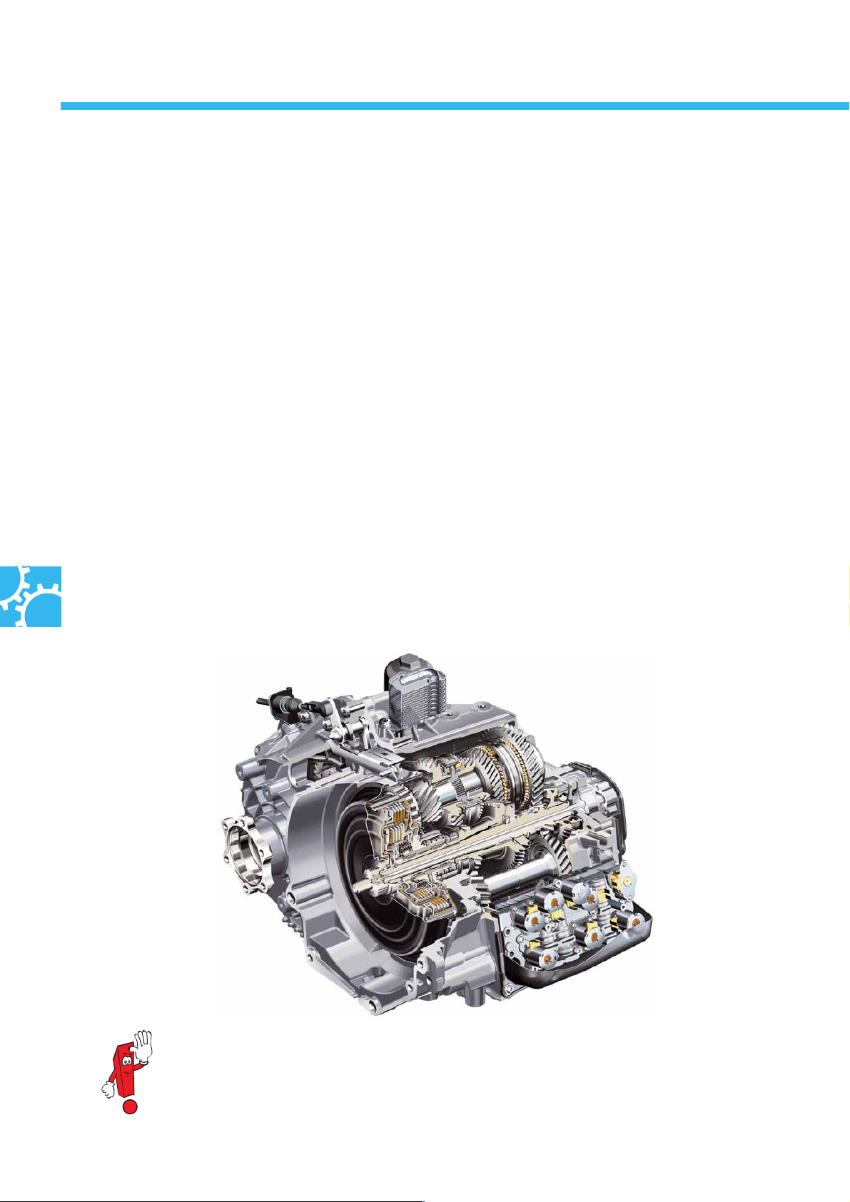
The 6-speed Direct-Shift Gearbox 02E
Following its successful, initial launch in the Golf and Touran, the Direct-Shift Gearbox is now also being fitted in
the Golf Plus.
The Direct-Shift Gearbox combines the advantages of
a manual gearbox:
- High efficiency
= low fuel comnsumption and
-Sportiness
= short shift times
with the advantages of an automatic gearbox:
-High comfort
= no manual clutch actuation or shifting
Thanks to its design, it meets both the requirements of
sporty drivers and also the comfort requirements of
drivers who prefer automatic gearboxes.
Special characteristics
- Six forward gears and one reverse gear,
- Standard and sports gearbox programmes,
- Tiptronic selector level and steering wheel switches,
-Mechatronics,
- Hill-holder function,
- Creep control,
- Pressure oil filter and oil cooler
mounted on the gearbox,
- Maximum torque 350 Nm.
The design and function of the selector lever and
ignition key removal lock correspond to those
in the Golf.
26
S338_049
Further information on the Direct-Shift Gearbox can be found in self-study programme No. 308
Page 27
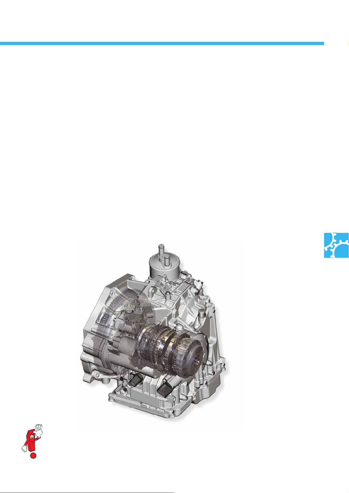
The 6-speed automatic gearbox 09G
The 6-speed automatic gearbox 09G is already very popular amongst customers in the Golf, Touran and New
Beetle. It sets new standards in terms of dynamics and economy in the segment of transversely mounted stepped
automatic gearboxes.
Special characteristics
- Low weight,
- High shifting comfort,
- Compact gearbox dimensions and
- High ratio between first and top gear.
The design and function of the selector lever and ignition key removal lock correspond to those
in the current models.
S338_120
Further information on these automatic gearboxes can be found in self-study programme No. 309
27
Page 28
Running gear
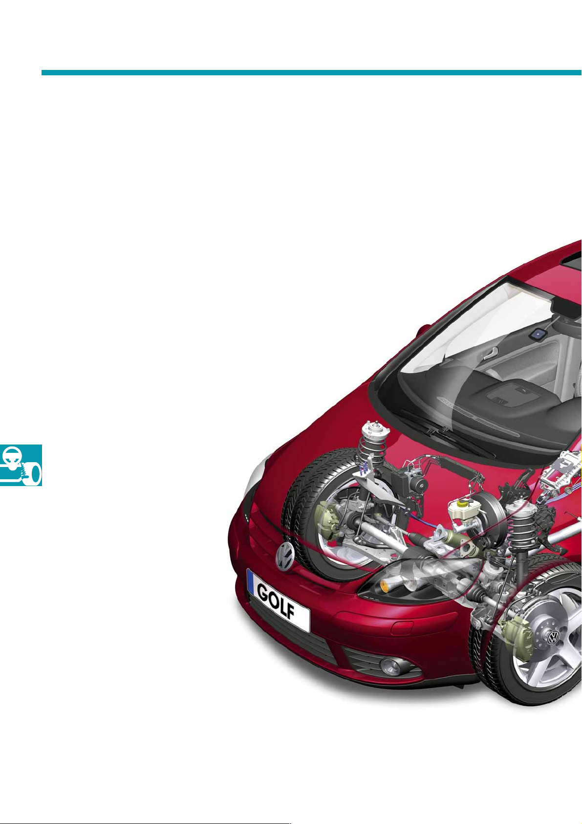
Overview of the Golf Plus running gear
With the exception of minor modifications, this is identical to that of the Golf 2004. The springs, the shock
absorbers and the anti-roll bars have been adapted so that the Golf Plus also offers the ride comfort typical of a
Volkswagen and guarantees a high level of vehicle dynamics.
To offer a high level of ergonomic comfort, the accelerator pedal inclination angle has been changed from 65° to
57°, and the upper section of the steering column has been shortened.
The functions of the accelerator pedal and the steering column are identical to
those in the Golf 2004.
● Continental Teves ESP MK60
● Brake assist system
● Front axle suspension struts
with high transverse rigidity
28
● Electromechanical power steering
system
Page 29
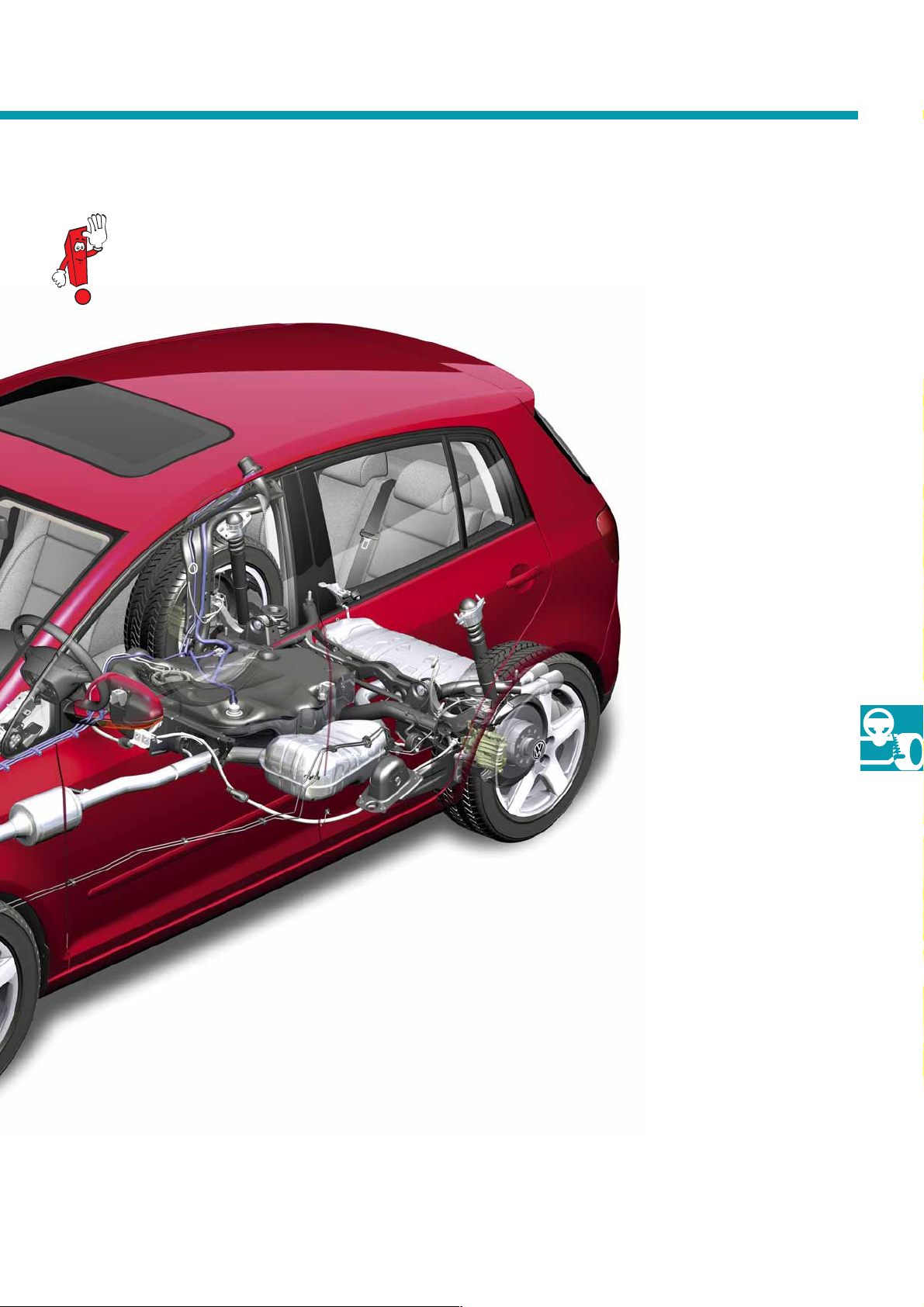
Further information on the running gear can be found in self-study programme No. 321
"The Golf 2004 running gear".
● Tyre pressure monitor (optional)
● Height and longitudinally-adjustable steering
column adapted to the seating position
● Vertical accelerator pedal with inclination angle
adapted to the seating position
S338_022
● Four-link rear suspension
29
Page 30
Electrical system
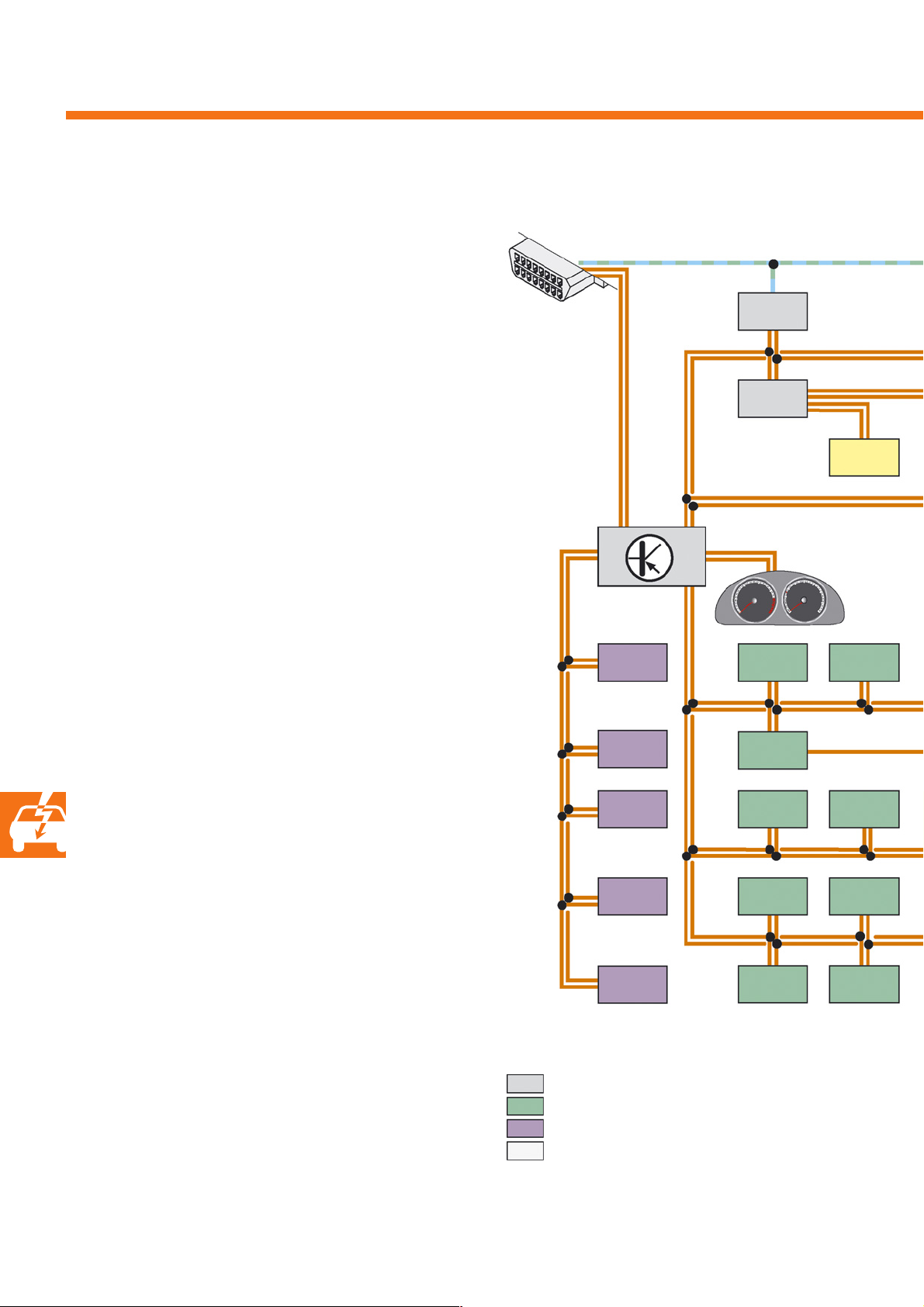
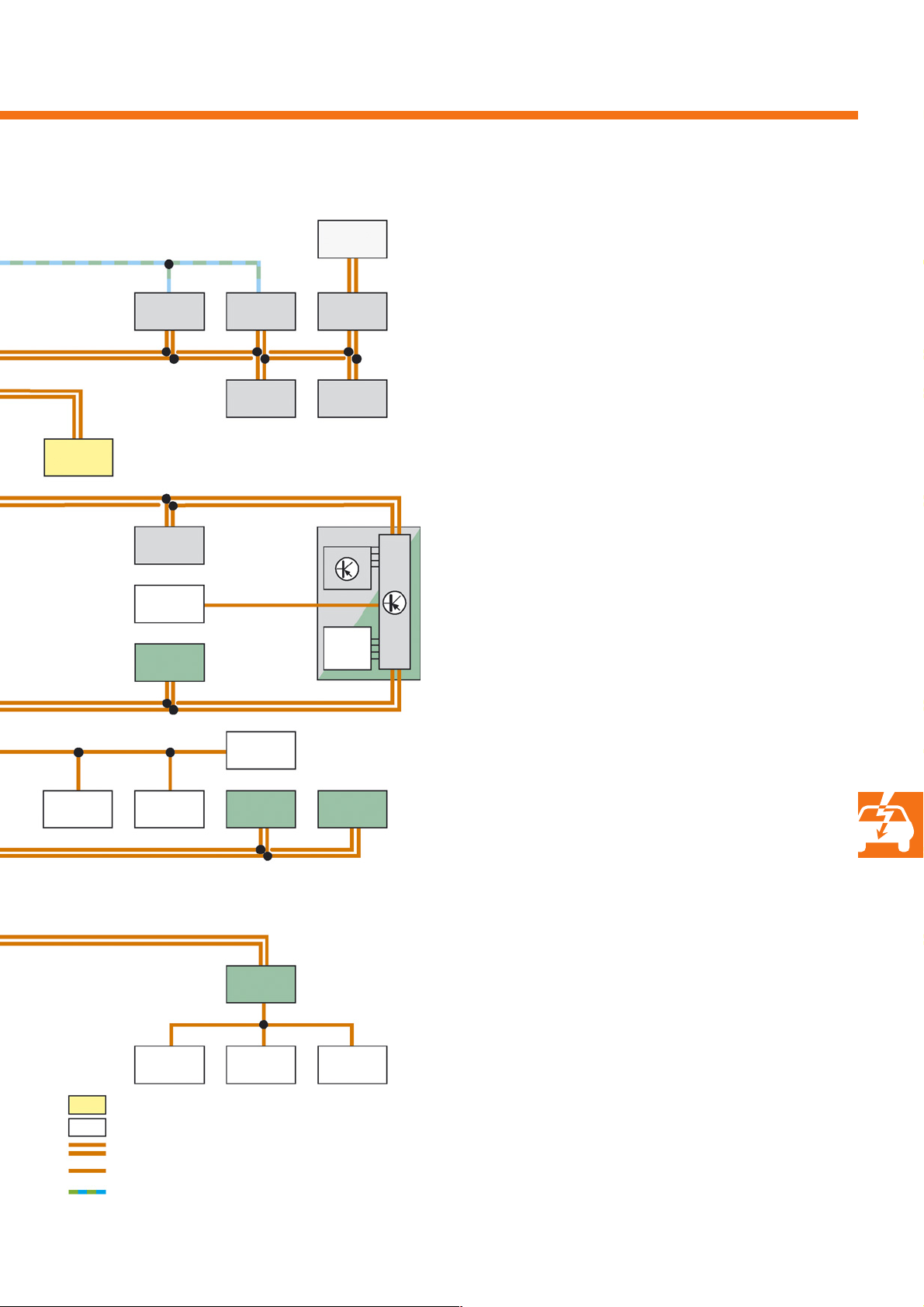
Overview of networked electronic control units
When fitted with maximum equipment, the following
electronic control module configuration can be found
in the Golf Plus.
As in the Golf 2004, the diagnostic interface for data
bus J553 acts as the interface between the different
data buses. It also ensures that data exchange
between data buses with different speeds
is carried out in an optimal manner.
In addition to the conventional comfort, powertrain
and infotainment CAN bus systems, internal
communication between the vehicle module or subsystem components frequently takes place via
separate CAN links.
These bus links, which are dependent on the
different manufacturers, may differ from the above
mentioned links, which operate with high- and lowspeed signal forms, not only in terms of their
transmission protocols, but also physically.
This different behaviour must be taken into
consideration in the case of direct measurements on
CAN systems and their electronic control units.
T16
b
J553
J503
R
J525
J364
R78
a
J220
J745
J345
J519J412
J255
J386
J387
J668
J334
J285
J608
J136
J388
J389
30
Legend
a
b
CAN powertrain data bus
CAN comfort data bus
CAN infotainment data bus
CAN sensor data bus
CAN instrument cluster data bus
CAN diagnostic data bus
Page 31
J667
J743*
J234
E221
J446
J400
J217**
J587*
J584
G419
J104
J500
G85
D
J527
J604J521G397
Legend
D Ignition/starter switch
E221 Operating unit in steering wheel
(multi-function steering wheel)
G85 Steering angle sender
G273 Interior monitoring sensor
G384 Vehicle inclination sender
G397 Rain and light detector sensor
G419 ESP sensor unit
H8 Anti-theft alarm system horn
J104 Control unit for ABS with EDL
J136 Seat and steering column adjustment
control unit with memory
J217** Automic gearbox control unit
J220 Motronic control unit
J234 Airbag control unit
J255 Climatronic (and Climatic) control unit
J285 Control unit with display in dash panel insert
J334 Immobiliser control unit
J345 Trailer detector control unit
J364 Auxiliary heater control unit
J386 Driver door control unit
J387 Front passenger door control unit
J388 Rear left door control unit
J389 Rear right door control unit
J393 Convenience system central control unit
J400 Wiper motor control unit
J412 Mobile telephone operating electronics control unit
J446 Parking aid control unit
J500 Power steering control unit
J503 Control unit with display for
radio and navigation
J519 Onboard supply control unit
J521 Front passenger seat adjustment with memory
control unit
J525 Digital sound package control unit
J527 Steering column electronics control unit
J533 Data bus diagnostic interface
J584 Front passenger side wiper motor control unit
J587* Selector lever sensor control unit
J604 Auxiliary air heater control unit
J608 Special vehicle control unit
J667 Power output module for left headlight
J668 Power output module for right headlight
J743* Mechatronics for Direct-Shift Gearbox
J745 Cornering light and headlight range control unit
R Radio
R78 TV tuner
T16 Diagnostic connection
J393
CAN cornering light data bus
LIN data bus
CAN data bus line
LIN data bus line
K line
* With Direct-Shift Gearbox only
** With automatic gearbox only
G384H8G273
S338_075
31
Page 32
Electrical system
The electrical system in the Golf Plus essentially corresponds to that fitted in the Golf 2004.
Changes particularly refer to the exterior lights.
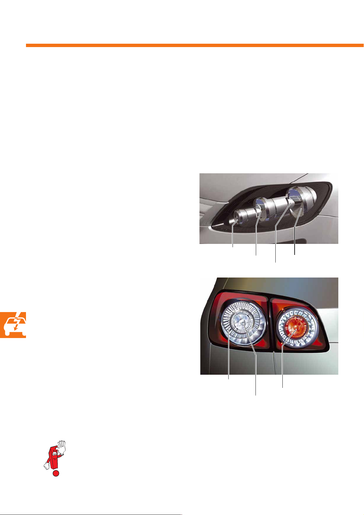
The exterior lights
Special characteristics
- Double round headlights with three round elements
- Split rear lights
The headlights
The double round headlights with dipped beam and
main beam reflector are fitted with H7 bulbs as
standard. The turn signals are equipped with a round
reflector.
The rear lights
In the Golf Plus, the rear lights are split into
two by the rear lid and are designed with multisection round elements. The rear light elements in the
body are designed in LED technology and contain the
tail light, brake light and turn signal functions.
The rear light elements in the rear lid are fitted with
conventional bulbs and contain the rear fog light on
the left-hand side and the reversing light on the
right-hand side.
In pure tail light mode, the LED light elements are
actuated with just 10-15% of their maximum power
output in comparison with the brake light and turn
signal function.
Turn signal
Main beam
Tail light,
turn signal
brake light
Tail light,
S338_065
Dipped beam
Side light
S338_064
Left: rear fog light
Right: reversing light
32
If individual, defective light-emitting diodes have to be repaired, the entire LED assembly has to be
exchanged.
Page 33
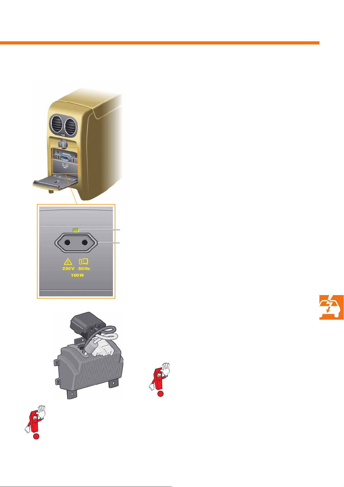
The inverter
As an optional extra, the Golf Plus can be equipped
with a 230V/50Hz socket for the European market or
a 115V/60Hz socket for North America. Depending on
the model, the European socket is designed without
an earthing contact.
The inverter has a continuous output of 150W.
For a short period of time of max. 2 minutes,
maximum power of 300W can be output.
In the inverter, the 12V DC low-voltage side and the
230V AC side are galvanically separated from each
other. The voltage of 230V is only available when the
engine is running in order to protect the battery.
S338_095
LED
European
socket
S338_062
When illuminated green, the two-colour LED indicates
normal operating mode on current consumption.
The LED's flashing red indicates overload.
The inverter and the socket are comprised to form an
assembly. This is located in the rear centre console
instead of the cup holder. If the socket or the inverter
is defective, the entire assembly is exchanged.
Further information can be found in self-study
programme 340 "The Passat 2006 – The electrical
system".
S338_076
Repairs to 230V systems must not be carried out in customer service workshops. If the socket or the
inverter is defective, the entire assembly must therefore be exchanged.
33
Page 34
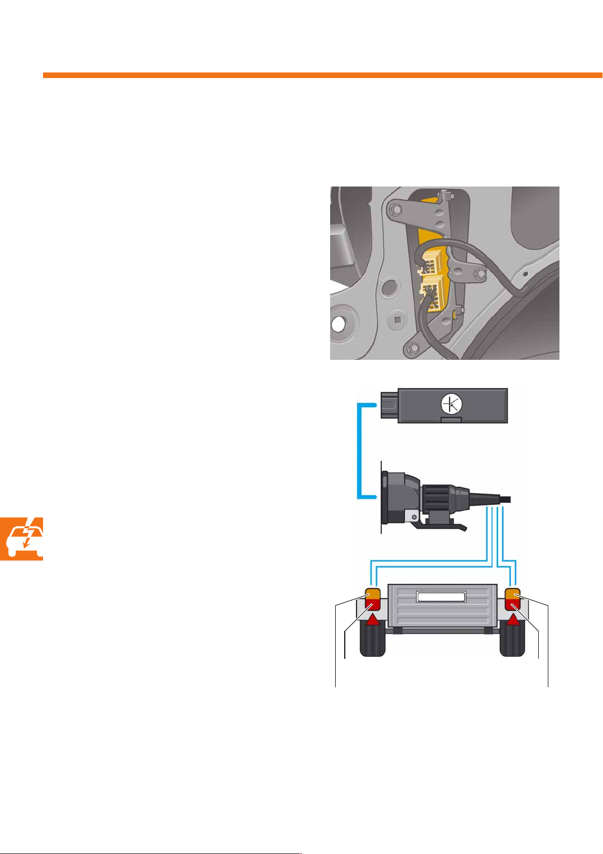
Electrical system
Trailer detector control unit J345
This ensures that the trailer's electrical components are integrated into the vehicle network.
Location
The trailer detector control unit is located behind the
luggage compartment trim on the left-hand
side panel.
Tasks
The trailer detector control unit determines
whether a trailer is connected to the trailer socket,
and makes this information available to other control
units via the CAN data bus.
It controls the trailer's lighting and also diagnoses the
functional capability of the majority of trailer bulbs.
As a CAN subscriber, it reads all messages required
for trailer operation, e.g. for the reversing light or turn
signals, and processes these to actuate the trailer's
corresponding lighting components.
This also applies to equipment-dependent
convenience electronics functions such as automatic
headlight control or the Coming-Home lighting and
safety functions such as the hazard warning lights in
the event of emergency braking.
S338_109
Trailer detector
control unit J345
Trailer socket
S338_104
Left side light
and brake light
Left turn signal Right turn signal
Right side light and
brake light
34
Page 35
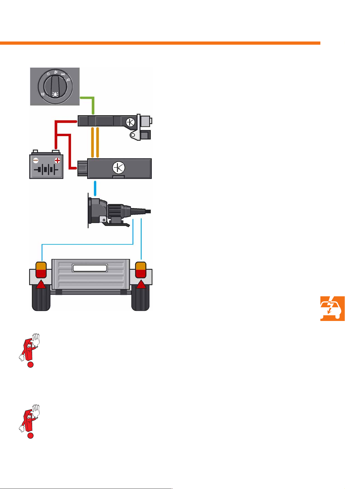
Rotary switch for lighting
However, the trailer detector control unit also feeds
messages into the CAN data bus, so that the affected
control units can switch to trailer mode.
Voltage supply
Onboard supply
control unit J519
CAN data bus
Trailer detector
control unit J345
Trailer socket
Tail lights on the trailer
This information is required:
- At the onboard supply system control unit to
actuate the rear fog light. This is switched off
during trailer operation to reduce the dazzle effect
to which the driver is exposed.
- At the ABS and ESP control unit to adapt the brake
system control functions to trailer operation.
- At the parking aid control unit to deactivate the
sensors for the rear sensing range.
- At the anti-theft alarm system to integrate the
trailer into monitoring when the trailer line is
connected. Since the microswitch in the trailer
socket has been omitted, this is carried out via bulb
sensing.
S338_115
When retrofitting a trailer socket, the socket must no longer simply be connected to the rear lights.
In this case, the onboard supply control unit is no longer able to carry out functions such as bulb diagnosis
via the defined bulb load or dimmed light actuation, because it is unable to distinguish between the
vehicle's lights and a possible short-circuit in the relevant power circuit.
A trailer with LEDs in its turn signals and rear lights cannot be detected, because its power consumption is
less than 5W. During trailer simulation, workshops must ensure that their test boxes provide this output
value of 5W as consumers.
35
Page 36
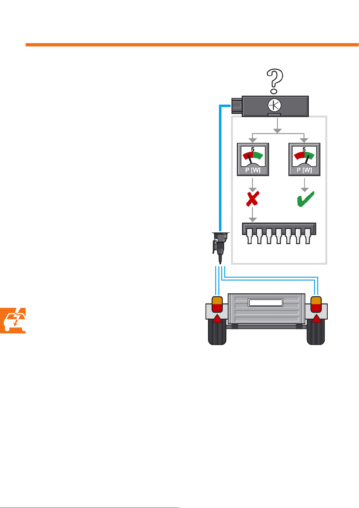
Electrical system
Function
Based on cold monitoring of the tail lights and turn
signals, the trailer detector control unit determines
whether a trailer is connected. This is carried out via
bulb current sensing. The minimum load which has to
be connected at the control unit outputs to achieve
this is 5W per output.
The advantage of current sensing is that the bulbs can
be monitored via the self-diagnosis function. If a bulb
is defective, an entry is made in the control unit's fault
memory.
This remains there until trailer re-connection is detected. This means that, even without the trailer, a defective turn signal or rear light can be detected in the
trailer electrics in the workshop.
J345
NOK OK
Self-diagnosis
The trailer detector control unit monitors all
components' inputs and outputs during vehicle
operation and in the workshop, e.g. during a control
element test. The reversing light and rear fog light are
the exceptions, as neither of these were legally
prescribed for trailers until recently.
The fault memory can contain five faults and is not
equipped with "self-healing". This means that static
and sporadic faults remain stored until a trailer is
connected again.
A fault may change its status from "static" to
"sporadic" if a defective bulb is exchanged whilst the
trailer is connected.
Fault memory
Current sensing
S338_116
36
Page 37
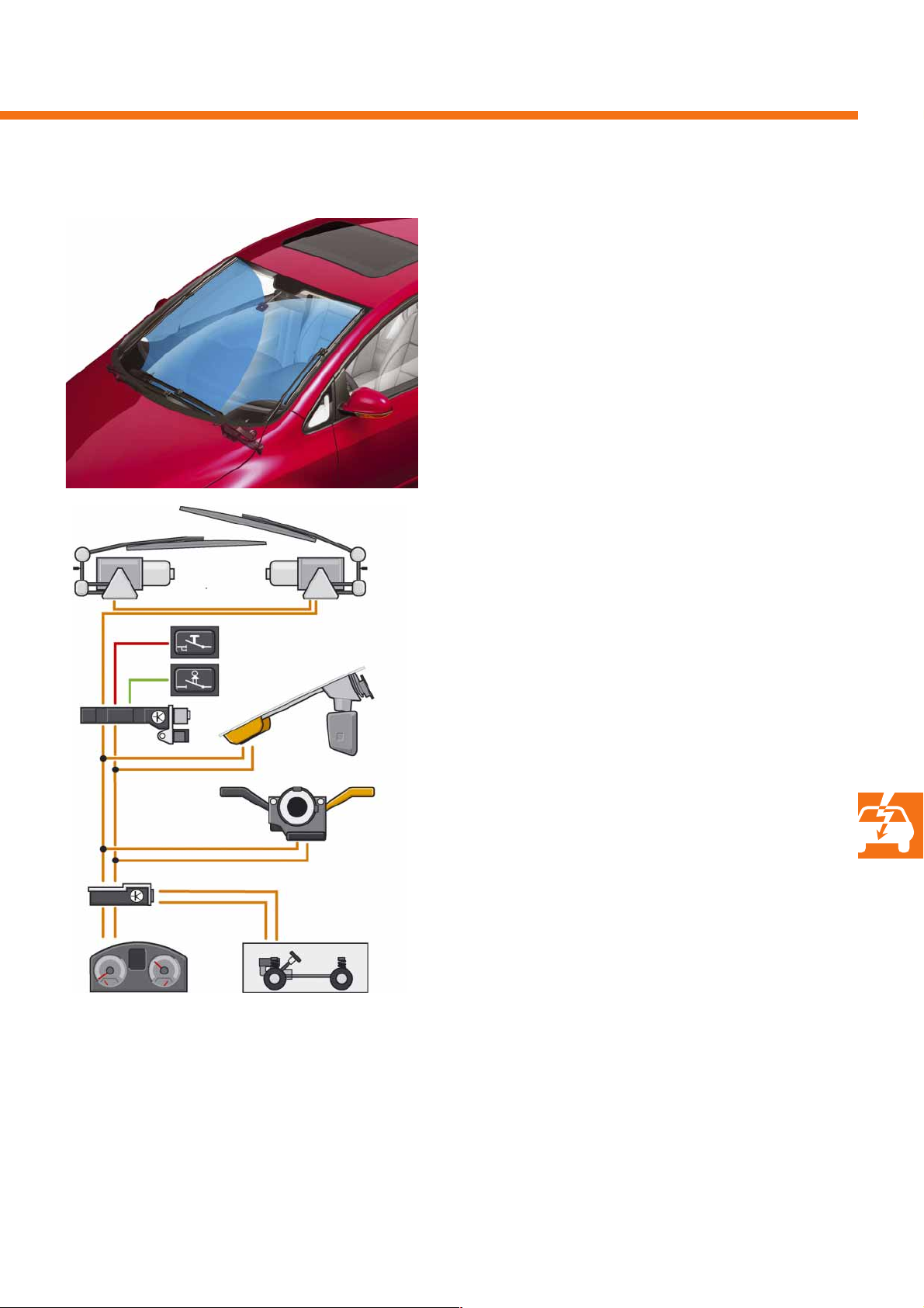
The windscreen wiper system
It is comprised of a contrarotating system with two
motors and no mechanical link between the wipers.
Due to the wiper system's contratotation principle,
the rain and light detector sensor has been located in
a new position in the Golf Plus.
J519
J533
J584
D
F266
G397
J400
J527
S338_080
E
Function
The wiper switch position is transmitted directly to the
steering column electronics control unit and then to
the onboard supply control unit via the CAN comfort
data bus.
Information on the activated wiper stage is transmitted by the onboard supply control unit, via the LIN
data bus, to the wiper motor control unit, and from
there to the front passenger side wiper motor control
unit. Both control units are located directly at the
wiper motors.
The wiper motor control unit controls the wiping
processes and actuates the front passenger side wiper
motor control unit in accordance with the
master-slave principle.
ab
S338_101
D - Ignition/starter switch
E - Wiper switch
F266 - Bonnet contact switch
G397- Rain and light detector sensor
J400 - Wiper motor control unit
J519 - Onboard supply control unit
J527 - Steering column electronics control unit
J533 - Data bus diagnostic interface
J584 - Front passenger side wiper motor control unit
a - Ambient temperature signal via CAN instrument cluster data bus
b - Vehicle speed signal via CAN powertrain data bus
37
Page 38
Convenience electronics
Rain closing
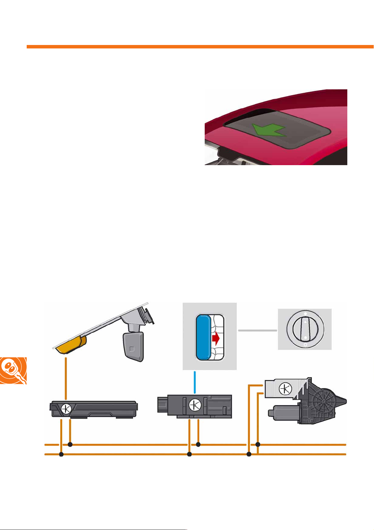
The "rain closing" convenience function" will be
introduced for the first time in Volkswagen's Golf class
along with the Golf Plus. This is a distributed function
in which the onboard supply, convenience and door
control units, the rain and light detector sensor and,
depending on the equipment fitted, the sliding roof
control unit work together.
Rain closing is initialised in the convenience control
unit. To achieve this, the "rain closing" function must
be switched on via the personalisation menu in the
instrument cluster. It has to be re-activated each time
after starting tie engine. i.e. "terminal 15 on".
S338_102
38
Rain and light detector sensor
LIN data bus
Onboard supply control unit
CAN comfort data bus
Sliding/tilting roof
module
Convenience
system central
control unit
Switch for
sliding roof
Door control unit
S338_103
Page 39

Function
Once rain closing has been activated, the convenience system control unit transmits a corresponding
message to the onboard supply control unit. Once this
has detected that the ignition has been switched off,
it sets the rain and light detector sensor to monitoring
mode. This mode is set to 12 hours as default.
If the rain sensor detects precipitation, it informs the
onboard supply control unit via the LIN data bus;
in turn, the former informs the convenience control
unit via the CAN data bus. Via separate CAN messages, this issues the command "close windows" to the
door control units. In accordance with the EU
Directive, the window drives' excess force limitation
function is also retained in the case of rain closing.
The command for the sliding/tilting roof (STR) is transmitted via a separate line from the convenience
control unit to the STR module.
Whilst the door control units confirm that the windows
have been closed, the STR drive does not provide the
convenience control unit with any feedback.
To avoid inadvertant deployment of the anti-theft
alarm system the sensitivity of the interior motion
sensors is reduced whilst rain closing is being
carried out.
Deactivation conditions
The function is deactivated following:
- Successful execution of rain closing,
- "Ignition on" status detected,
- Expiry of the monitoring period.
39
Page 40
Convenience electronics
Rain and light detector sensor G397
Location
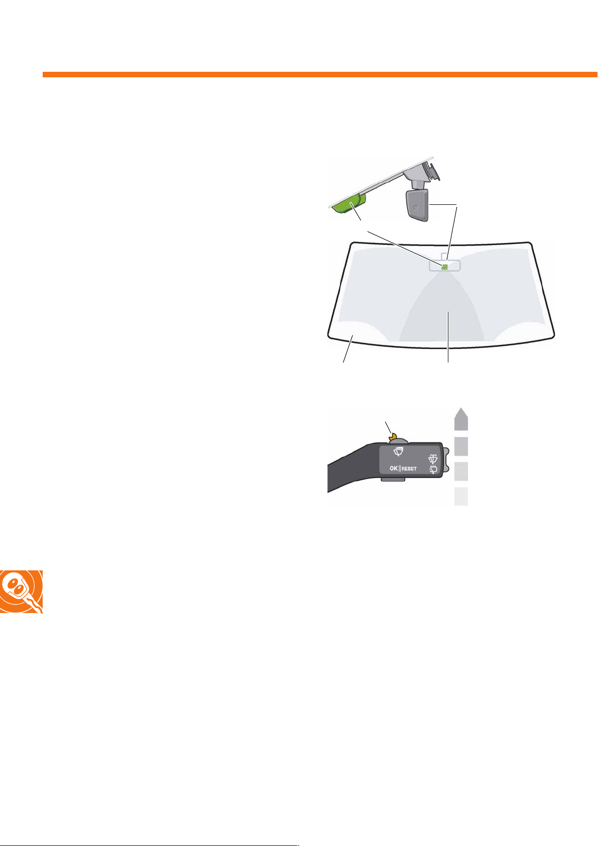
The rain and light detector sensor is located in the
Golf Plus in such a way that it is positioned as high as
possible, centrally, in the wiping overlap range of
both wiper arms.
Task
The rain and light detector sensor only operates in
automatic mode if the wiper lever is set to the
"intermittent" position for rain detection and the light
switch is set to the "automatic headlight control"
position for light detection. The rain and light detector
sensor then ensures, when rain is detected on the
windscreen, that the wipers are actuated from zero to
the maximum number of wiper cycles according to the
quantity of precipitation, and that the headlights are
switched on in twilight conditions.
Sensor
Windscreen
Intermittent wiper
regulator E38
S338_132
Interior rear-view
mirror
S338_131
Wiping overlap range
Wiper level 2
Wiper level 1
The rain and light detector sensor independently
adapts to the windshield's tinting.
At wiper lever level 1, in which the wipers operate at a
speed of 42 cycles per minute without rain sensing,
the wiper speed can be independently increased up
to 60 cycles per minute with rain sensing, depending
on the quantity of precipitation.
In the case of wiper operation without rain sensing,
this value corresponds to level 2. In level 2, rain detection has no influence on the wiper speed. In this case,
the wipers operate at a constant 60 cycles per minute.
Rain sensor on/
intermittent wiping
S338_136
Off
The intermittent wiper regulator can be used to
individually set the sensitivity of the rain detector.
In vehicles without a rain detector, the regulator is
used to set the length of the intervals.
40
Page 41
Structure
Windscreen
Optical element
LED
Remote sensor
Sensor housing
Photo diode
Adhesive film
S338_125
Ambient light sensor
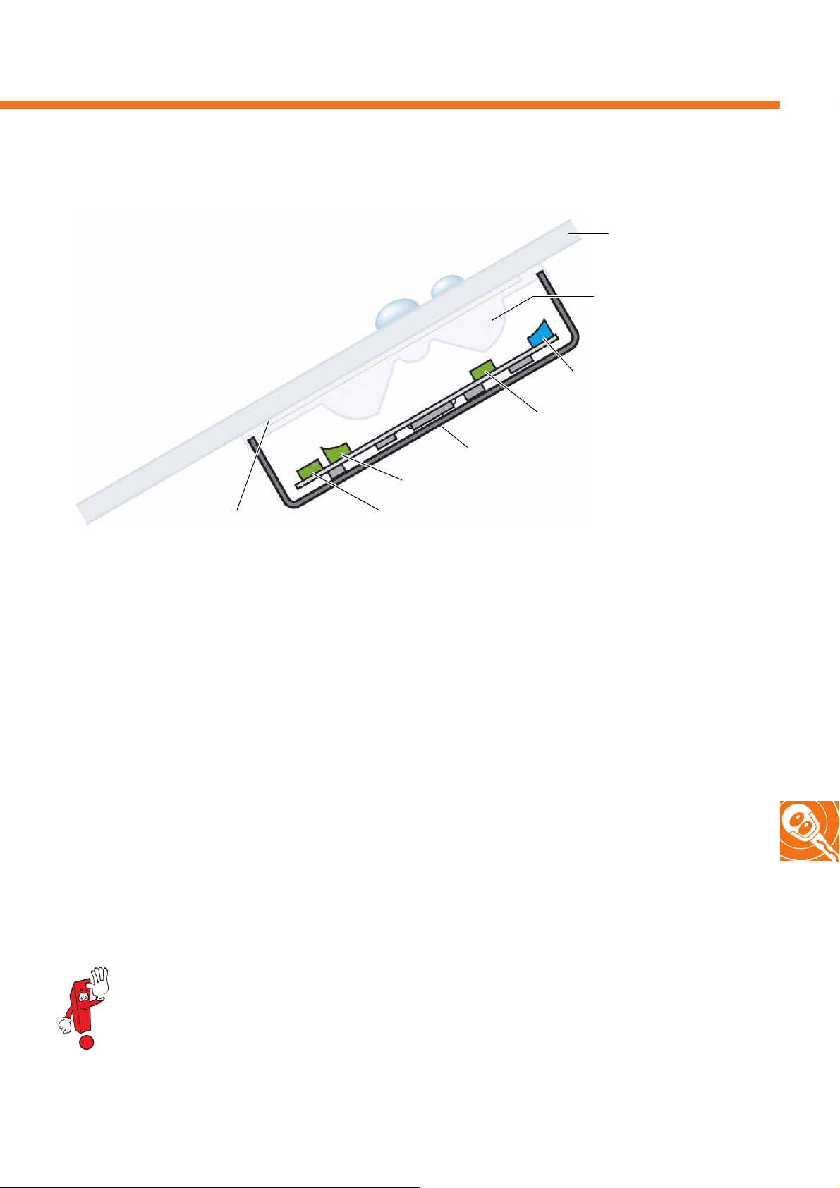
The rain and light detector sensor is comprised of a combination of light-sensitive sensor elements and an LED.
All components are mounted on a printed circuit board in the sensor housing.
An optical element rounds off the sensor housing towards the windscreen. The optical element's task is to bundle
and align the outgoing and incoming light. The entire sensor is secured to the windscreen using an adhesive film.
2
The sensed area measures 300mm
.
The LED and a photo diode are used for rain detection, whilst an ambient light and a remote
sensor are used for light detection.
The priority of both rain and light detection is subordinate to manual actuation of the relevant switch
elements. This means that even if these assistance functions malfunction, manual activation of the wipers
and driving lights always takes precedence.
41
Page 42
Convenience electronics
Rain detection function
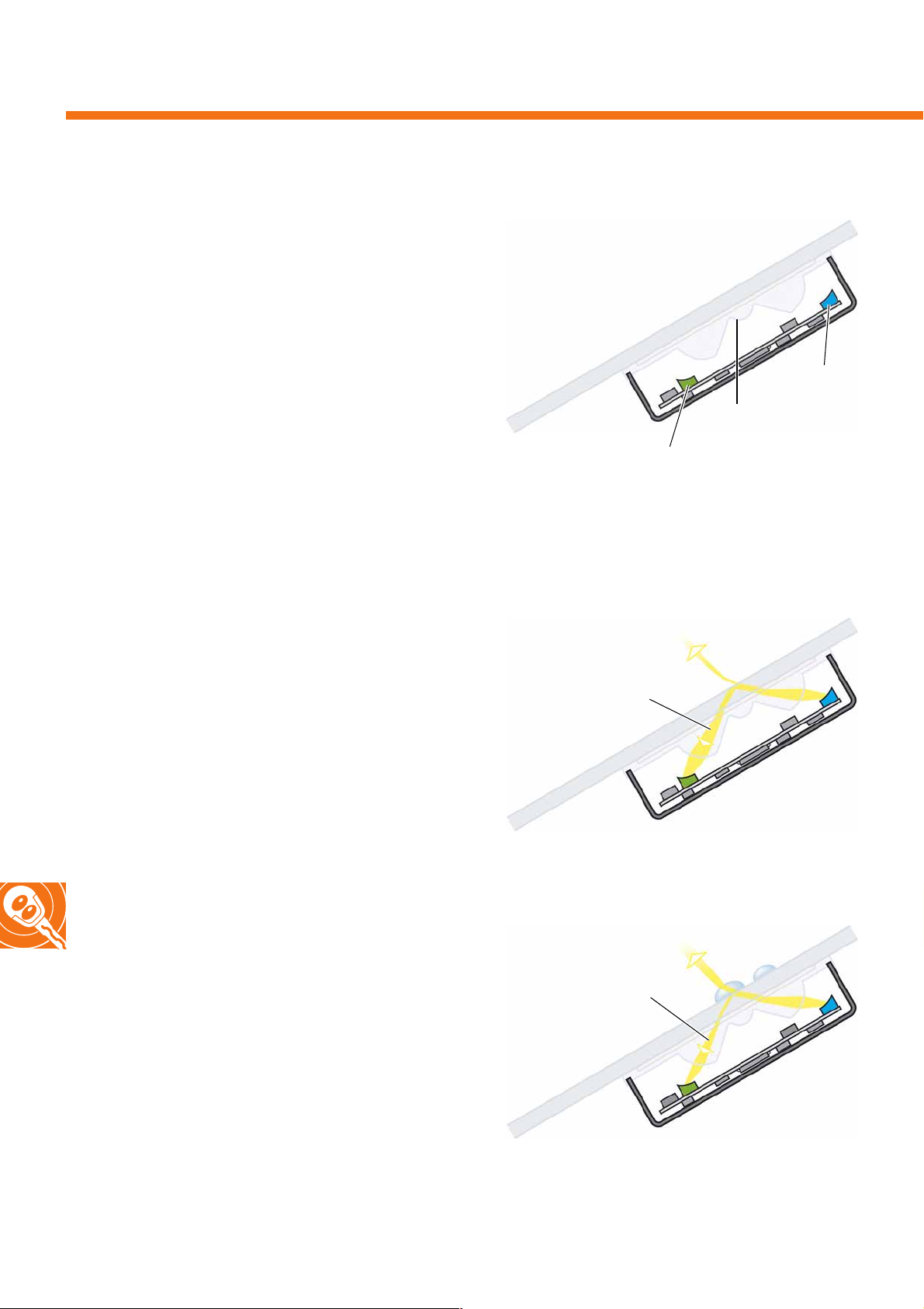
The sensor's core elements are an LED and a photo
diode. The sensor's basic principle is that the light
emerging from the LED is partially reflected by the
surface of the windscreen and, bundled by the optical
element, hits the photo diode.
LED
Optical element
The degree to which the diode's light is reflected,
and therefore the volume of light which hits the photo
diode, changes if the windscreen is coated with water
droplets or a film of water. The greater the coating,
the less light is reflected due to light refraction.
The photo diode's output signal can therefore be used
to calculate the quantity of precipitation.
The rain detrctor response time, i.e. the time which
passes between the detection of precipitation and the
emission of the output signal to the wipers, is less than
20ms.
S338_127
Reflection with a dry windscreen
Large quantity of light
S338_128
Reflection with a wet windscreen
Photo diode
= no rain
42
Small quantity of light
= rain
S338_129
Page 43
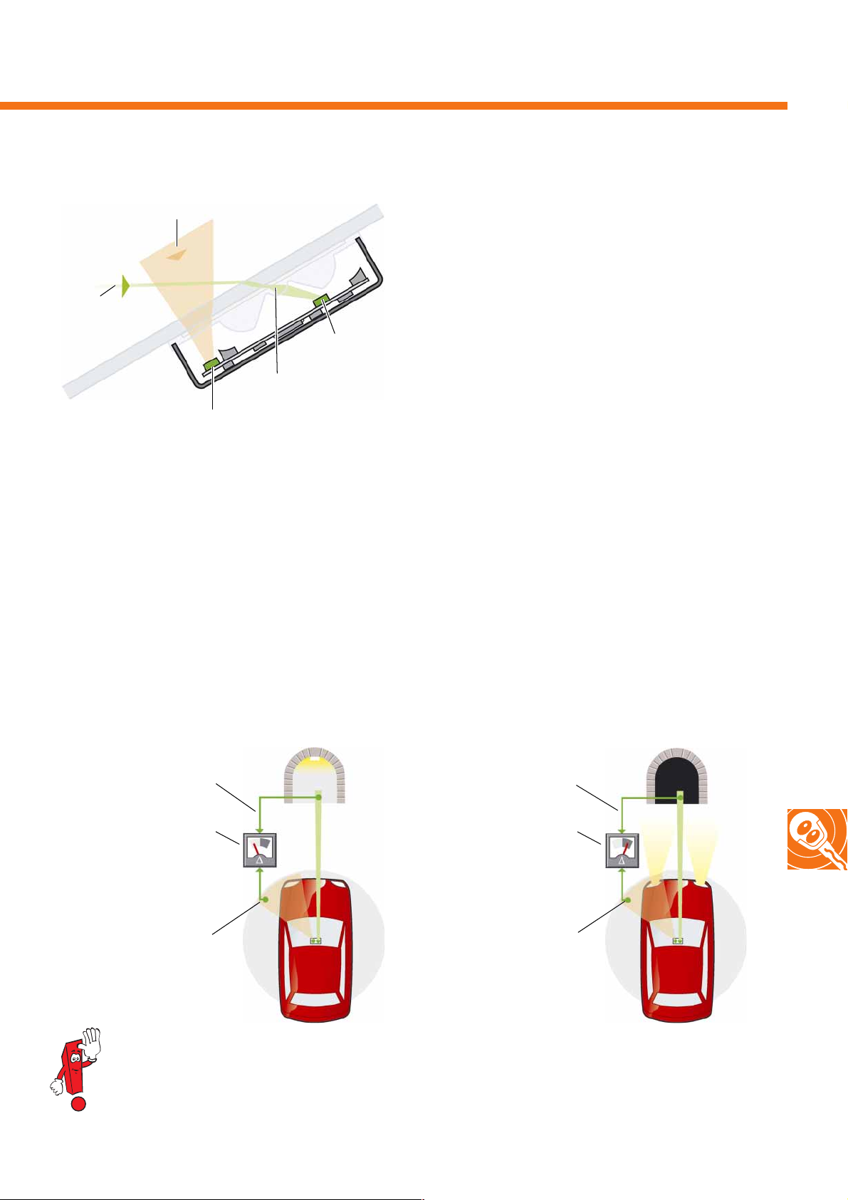
Light detection function
Incoming ambient light
To distinguish between light conditions, the rain and
light detector sensor is fitted with different light
sensors. An ambient sensor detects the light
conditions in the vehicle's immediate vicinity and a
remote sensor senses the light conditions at a
Light from
remote sources
S338_130
Remote sensor
Optical element
Ambient light sensor
distance of up to three vehicle lengths in front in the
direction of travel.
The system detects a general decrease or increase in
brightness and switches the driving lights
on or off when the automatic headlight control
function is activated.
From the difference between both sensors' signals, the system is able to determine e.g. that the vehicle is entering a
tunnel, thereby switching on the driving lights when the vehicle enters the tunnel at the latest. The system's internal,
logical link ensures that the driving lights are only switched off once the ambient light sensor has detected an
adequate brightness value.
If the rain detector is also active in addition to the light detector, correspondingly heavy precipitation also leads to
activation of the driving lights.
Remote detection
Difference in brightness
less than
activation threshold value
= lights remain off
Ambient light detection
S338_133
The light detection function does not react to fog or underpasses.
In these cases, the driving lights have to be switched on manually.
Remote detection
Difference in brightness
greater than
activation threshold value
= lights are switched on
Ambient light detection
S338_134
43
Page 44
Radio and navigation
The radio systems in the Golf Plus
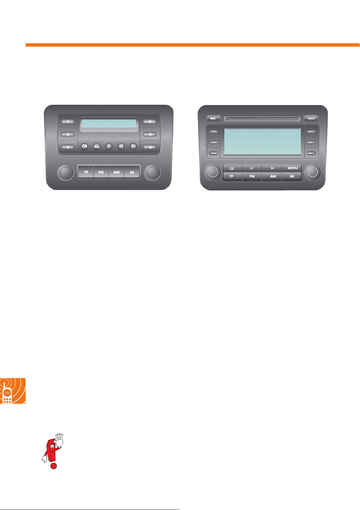
Radio R100
S338_088
The R100 target group is major customers,
e.g. vehicle fleet operators.
This radio unit offers the following functions:
- Two loudspeaker channels
(front only, 20 Watts each)
- RDS FM/AM European radio (AM without LW)
- Control system for external 6-fold CD-changer
- Telephone control system (hands-free)
- Speed-dependent
volume control (GALA)
- Self-diagnosis with loudspeaker diagnosis
-Transport mode
(current requirement reduction during transport
and idle times)
Radio RCD 300
S338_089
Radio RCD 300 is available as the standard radio
system for private customers.
It offers the following functions:
- Two or four loudspeaker channels
(20 Watts each)
- RDS FM/AM European radio (AM without LW)
- Indication of the stored stations with
RDS names in the display
- FM 2-tuner diversity
- Control via the multi-function steering wheel (MFL)
and multi-function indicator (MFI)
- Integrated single-CD player,
- Control system for external 6-fold CD-changer
- Telephone control system (hands-free)
-GALA
- Self-diagnosis with loudspeaker diagnosis
-Transport mode
- Driving school function (possible indication of
turn signal function and speed via the
unit's display)
44
Due to the change in installation position and reading angle in comparison with the Golf 2004,
the displays for the radios fitted in the Golf Plus have been redesigned. This results in a different
part number.
Page 45
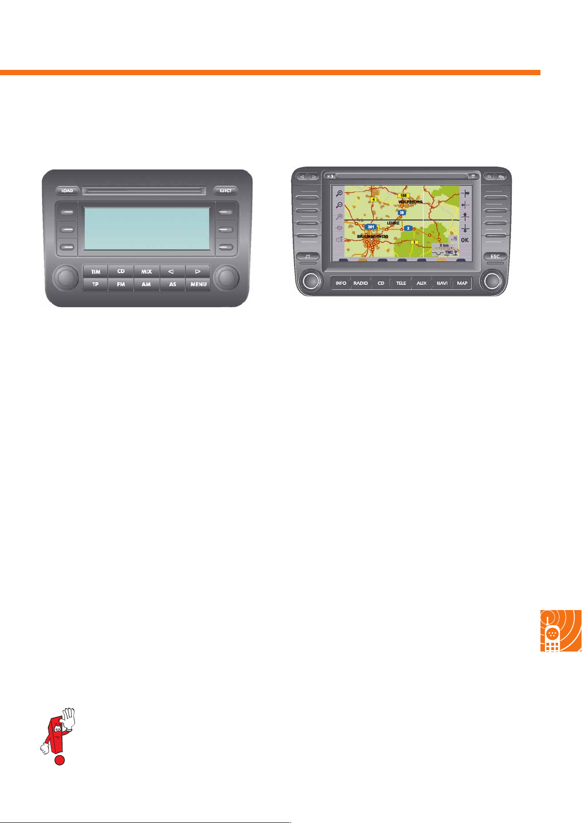
Radio RCD 500
Radio/navigation system MFD 2
S338_091
S338_090
This, or a higher-quality radio, is required to equip the
Golf Plus with the digital sound package DSP. It offers
the folloing functions
- Four loudspeaker channels (20 Watts each)
- RDS FM/AM European radio (AM without LW)
- Indication of the stored stations with RDS names in
the display
- FM 2-tuner phase diversity
- Control via the MFL and MFI
- Integrated single-CD player
- Control system for external 6-fold CD-changer
- Telephone control system (hands-free)
-GALA
- Traffic Information Memory (TIM)
- Vehicle model-specific sound adaptation
- Self-diagnosis with loudspeaker diagnosis
- Transport mode
- Optional connection of an external
sound amplifier
A radio system with an integrated navigation
system is also available for the Golf Plus.
The operating sequences are similar to those of the
radio/navigation system fitted in the Touareg.
It offers the following functions, etc.:
- Multi-colour display (MFD)
-Dynamic guidance
- Four loudspeaker channels (20 Watts each)
- RDS FM/AM European radio (AM without LW)
- Indication of the stored stations with RDS names in
the display
- External diversity changeover box
- Control via the MFL and MFI
- Control system for external 6-fold CD-changer
- Telephone control system (hands-free)
-GALA
-TIM
- Self-diagnosis with loudspeaker diagnosis
- Optional connection of an external sound amplifier
The cover frame has to be removed to remove or install a radio, in order to access the
threaded connection located behind it.
45
Page 46
Radio and navigation
The antenna concept
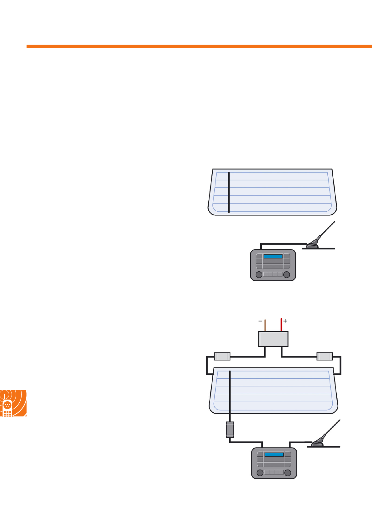
Four antenna equipment alternatives are currently available for the Golf Plus:
- Roof antenna and rear window with an antenna structure without connection option,
- Roof antenna and rear window with an antenna structure and one connection option,
- Roof antenna and rear window with two antenna structures and one connection option, and
- Roof antenna and rear window with two antenna structures and two connection options.
A rod or tri-band antenna may be fitted as the roof antenna.
Roof antenna and rear window with an antenna
structure without connection option
If this equipment is fitted, e.g. radio R100 is connected
to the roof antenna. As in the case of the variant
"without radio", the integrated rear window antenna
has no connection option, with the result that a
telephone, navigation and telestart cannot be
implemented with this version.
Roof antenna and rear window with an
antenna structure and one connection option
Both antennae are used by one radio (as of RCD 300)
to exploit the advantages of antenna diversity.
This means that, thanks to an integrated diversity
switch, the radio automatically uses the antenna with
the stronger input signal.
Telephone, navigation and telestart are not available
in this case.
Roof
antenna
S338_110
Radio
AM blocking circuit
FM blocking circu it FM blocking circuit
46
Roof
antenna
S338_111
Radio
Page 47

Roof antenna and rear window with two antenna
structures and one connection option
AM blocking circuit
FM blocking circu it FM blocking circuit
FM impedance
converter
Radio
e.g. telephone
The roof antenna is used for the telephone,
navigation or telestart. The rear window antenna's
connection option is used for the radio, e.g. the R100.
Roof
antenna
S338_113
Roof antenna and rear window with two antenna
structures and two connection options
FM blocking circuit FM blocking circuit
FM impe-
dance
converter
External diversity box
(in MFD2 mode)
AM/FM impe-
dance converter
E.g. navigation
AM blocking circuit
Roof
antenna for
GSM/GPS/
telestart
Telephone, telestart
S338_112
The roof antenna is used for the telephone,
navigation and telestart. The two rear window
antenna connections are used for the radio.
No external diversity box is installed if the vehicle is
equipped with radio RCD 300 or RCD 500.
The GPS link to the roof antenna is also omitted in this
case.
If the Golf Plus is supplied without
preparation for antenna installation, a
dummy antenna seals the antenna bore in
the vehicle's roof. Whilst the rear window is
equipped with the integrated antenna
structure, it does not offer any
connection option.
47
Page 48
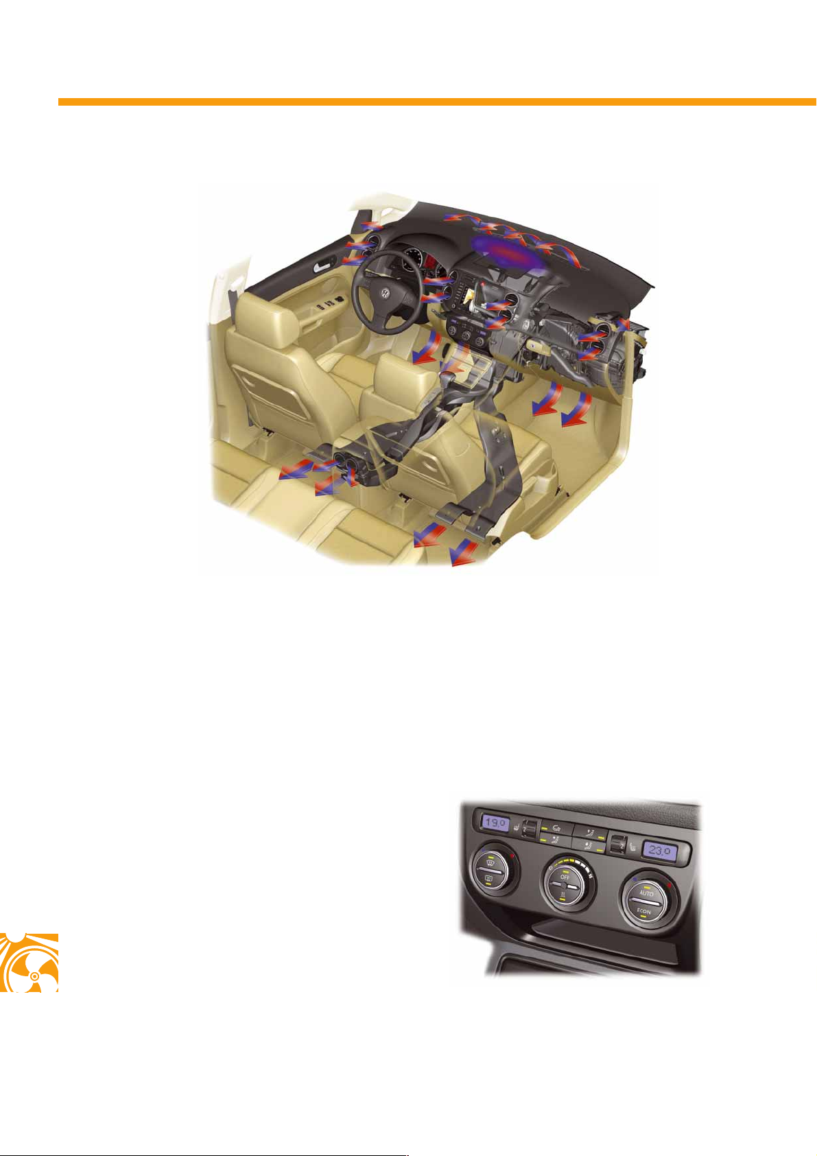
Heater and air conditioner
Climate control
S338_059
Three different systems are available in the Golf Plus:
- The manual heater and ventilation system,
- The semi-automatic heater and air conditioner "Climatic" and
- The heater and air conditioner "Climatronic".
An identically designed air conditioner unit, which has been adapted to the relevant vehicle equipment, is used for
both air conditioners. The main difference is in the number and design of the air distribution
flaps. For example, the 2C-Climatronic is fitted with an additional fresh air/air flow flap.
Depending on the vehicle's equipment, the heater
and air conditioner control panels differ.
Four different variants are available:
- With or without instant heat button for the
auxiliary coolant heater and
- With or without potentiometer for the seat heating.
48
All temperature- and ventilation-relevant control
elements and the air conditioner control unit are
integrated into the control panel.
S338_060
Page 49
S338_041
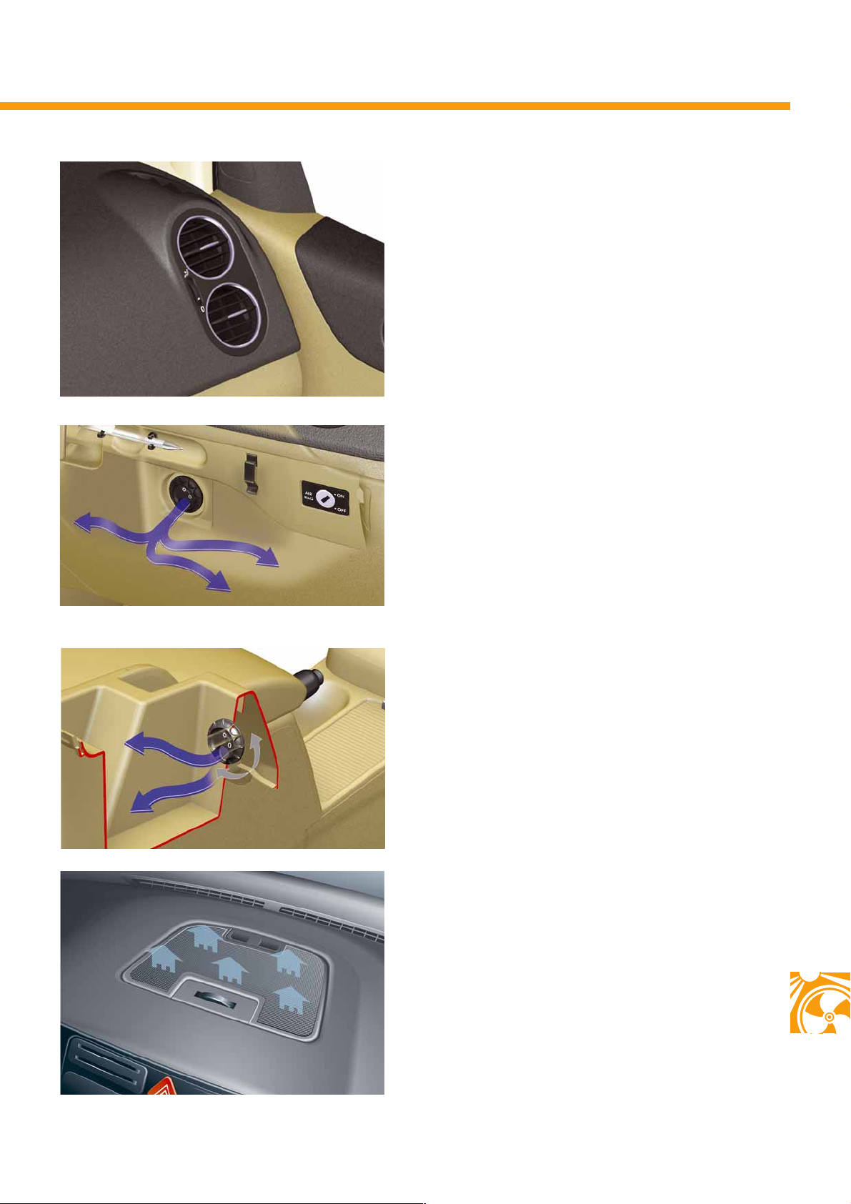
The vents are sub-divided. This doubles the number
of vents in the upper area of the dash panel to eight,
and enables more individual adjustment.
Better air output is made possible thanks to the larger
air duct cross-sections. The cross-sections of the rear
footwell vents have also been increased. This also
improves ventilation in this area.
The glove box is supplied with cooled air,
which is diverted directly downstream of the
evaporator.
S338_081
S338_042
The temperature-controlled storage compartment in
the Highline centre console has room for two cans of
drink. The temperature corresponds to the pre-set
interior temperature.
In the Climatronic system, a diffusor offers
indirect and draught-free ventilation.
S338_078
49
Page 50
Heater and air conditioner
The Climatic system
22°C
S338_061
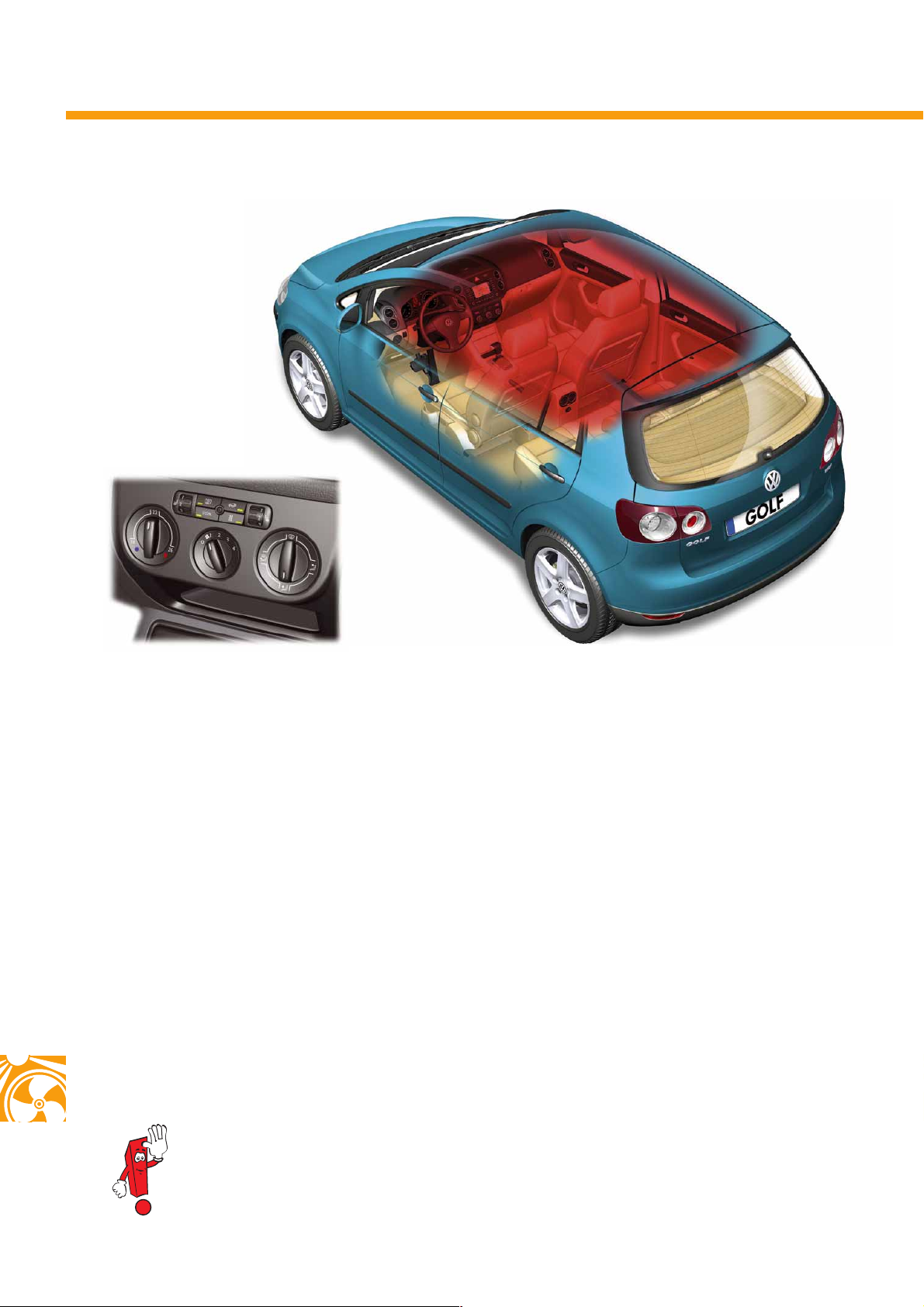
In the Climatic system, the vehicle's entire interior is
comprised to form a single climatic zone.
The desired temperature is set at the left
rotary switch.
The rotary switch is linked to a potentiometer,
which passes the temperature commend on to the
Climatic control unit. The control unit then forwards a
calculated flap position value to the temperature flap
positioning motor.
Climatic is able to control the pre-set temperature by
monitoring the vent and interior temperature.
S338_123
The air distribution flaps are actuated via a
flexible shaft in the Climatic system.
The air conditioner is switched on and off via the
ECON button. In ECON mode, the additional heater
is also switched off in vehicles fitted with diesel
engines. The Climatic air conditioner unit is equipped
with a combined fresh air/recirculated air flap.
50
Further information can be found in self-study programme No. 318 "The Golf 2004".
Page 51
The 2C-Climatronic system
23°C
19°C
S338_060
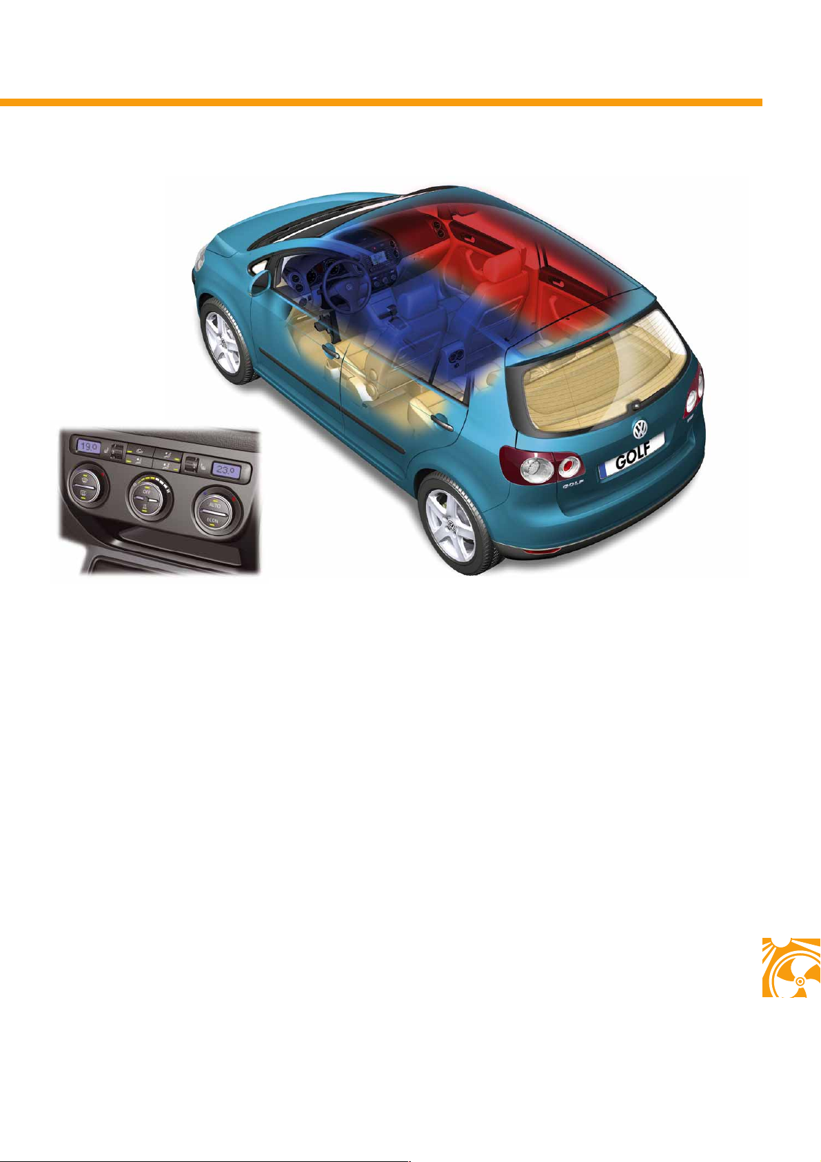
In the 2C-Climatronic system, the interior is subdivided into two climatic zones. This means that the
temperaturs desired on the driver and front
passenger side can be set independently of each
other. The climatic zones are separated by two
temperature flaps inside the air conditioner unit.
All flaps, air distribution and the temperature
are actuated via positioning motors with an
integrated feedback potentiometer. Maintenance of
the pre-set interior temperature and optimal air
distribution is thereby controlled and monitored by
the Climatronic control unit.
The 2C-Climatronic system can be operated in
automatic or manual mode.
S338_124
In addition to the Climatic system, 2C-Climatronic is
fitted with a fresh air flow flap, which is closed as of
100km/h as speed increases, in order to keep the
volume of fresh air which is supplied constant.
One further function which is available is speeddependent blower reduction, which reduces the air
conditioner's flow noises at low speed. In cooling
mode, this is compensated by lowering the vent
temperature and by raising the ventilation temperature in heating mode.
To prevent the windows from misting when the
compressor is switched off and the windscreen wipers
are switched on, the defrost flap is automatically
opened further to conduct more air to the windscreen.
51
Page 52
Heater and air conditioner
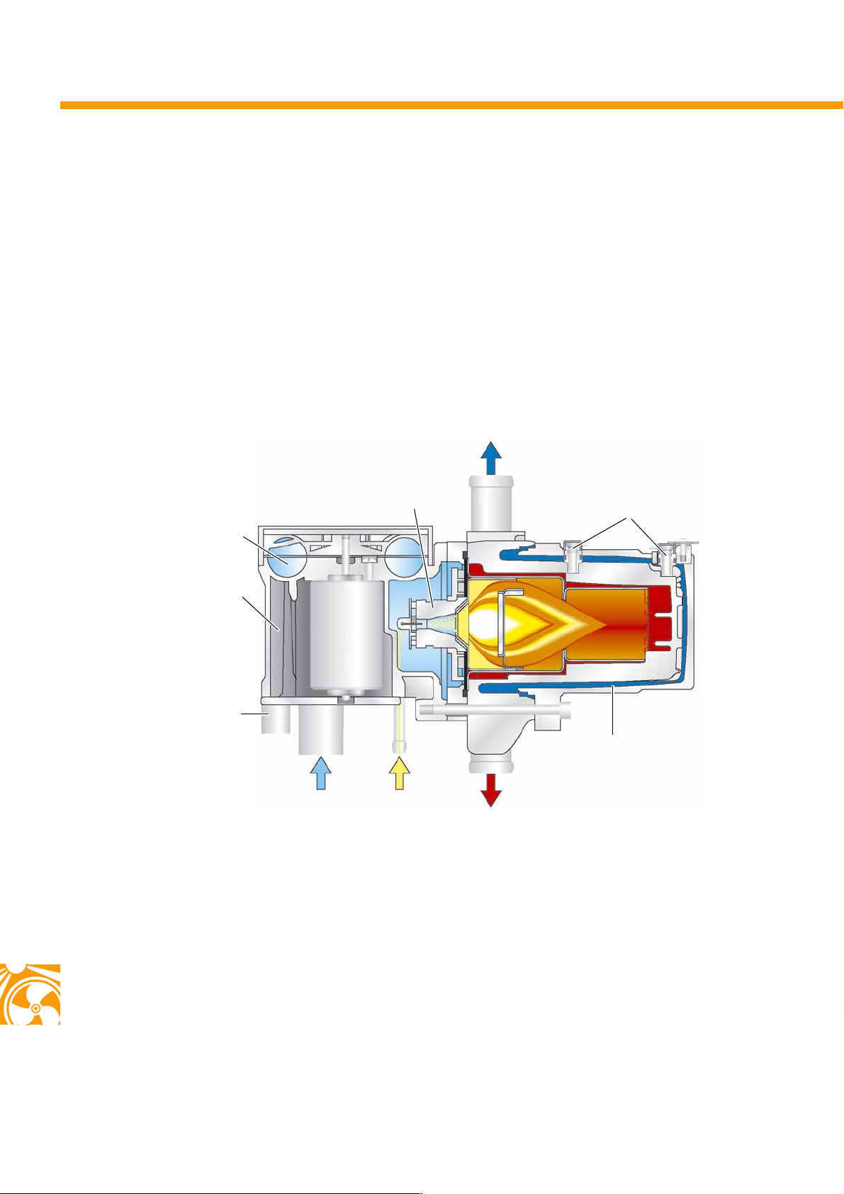
The Thermo Top V auxiliary coolant heater
The Golf Plus can be fitted with the optional Thermo Top V auxiliary coolant heater.
This undertakes the following tasks:
● Acts as an auxiliary heater for heating the vehicle interior and defrosting the vehicle's windows,
● Acts as stationary ventilation to lower the interior temperature when the vehicle is parked in the sun,
● Acts as an additional heater in vehicles with petrol or diesel engines (fitted as standard in diesel engines).
Structure
Combustion air blower
Control unit
Electrical connection
Combustion air
inlet
Ventu ri no z zle
Fuel
inlet
Water outlet
Temperature sensor
S338_045
Heat exchanger
Exhaust gas outlet
52
Special characteristics
- The auxiliary coolant heater control unit is integrated into the heater unit.
- The electrical contacts for the combustion air blower are inserted directly into the control unit.
- The auxiliary coolant heater is fitted with a second NTC temperature sensor for controlling and monitoring the
water temperature.
- The combustion air enters the combustion chamber via a venturi nozzle and thereby draws in the fuel
delivered by the metering pump from the fuel line.
Page 53
The venturi nozzle
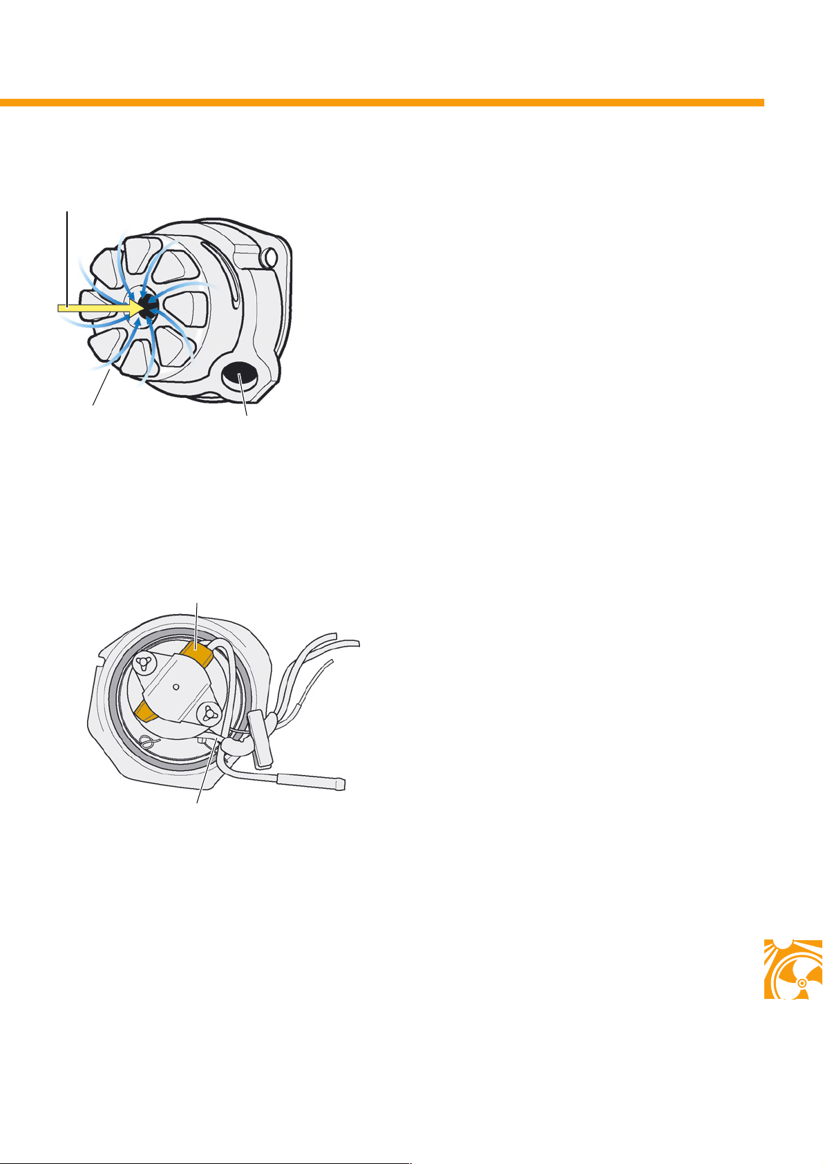
Fuel inlet
Combustion air inlet
Heater element mounting
The fuel pre-heater
PTC heater element
The intaken air is guided through a ceramic housing,
which is shaped as a venturi nozzle. As a result of this,
the air delivered by the combusion air blower is accelerated to approx. 50 m/s.
The incoming fuel is therefore drawn from the fuel line
and swirled.
S338_046
The Thermo Top V system is fitted with a PTC element
for pre-heating fuel; this enables the use of RME
(rapeseed methyl ester).
The fuel is heated directly prior to emerging from the
fuel line. To do this, the PTC heater element is switched
on for one minute at ambient temperatures of less
than 5°C.
Fuel supply line
S338_047
53
Page 54
Heater and air conditioner
Activation of Thermo Top V
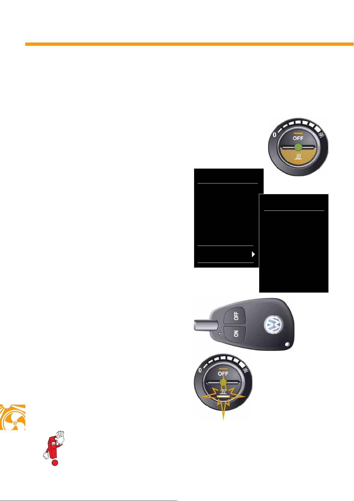
There are three ways of activating the Thermo Top V auxiliary coolant heater.
The "heater" or "ventilation" functions can be set in the dash panel insert display.
1. Activation of the auxiliary coolant heater via the
instant heat button on the control panel.
2. Programming the auxiliary coolant heater via the
multi-function indicator (MFI) with the data
display protocol (DDP).
In this case, programming is carried out via the display in the dash panel insert in the "auxiliary heater"
sub-option (personalisation).
3. The separate radio remote control can be used for
switching on and off functions. An indicator lamp
indicates whether the radio signal has been received
by the auxiliary coolant heater.
SETTINGS
Time
Winter tyres
Language
Units
Light & visibility
Comfort
Auxiliary heater
S338_070
AUXILIARY HEATER
Activation 1
Activation 2
Activation 3
Runtime
Operating mode
Weekday
Default setting
S338_069
54
The instant heat button in the control panel shows the
status of the auxiliary coolant heater: if active,
the yellow feedback LED lights up. If a programmed
duty cycle for the auxiliary coolant heater is active,
the feedback LED lights up for approx. 10 seconds
after the ignition has been switched off.
Further information can be found in self-study programme No. 318 "The Golf 2004".
S338_114
Page 55
Special tools
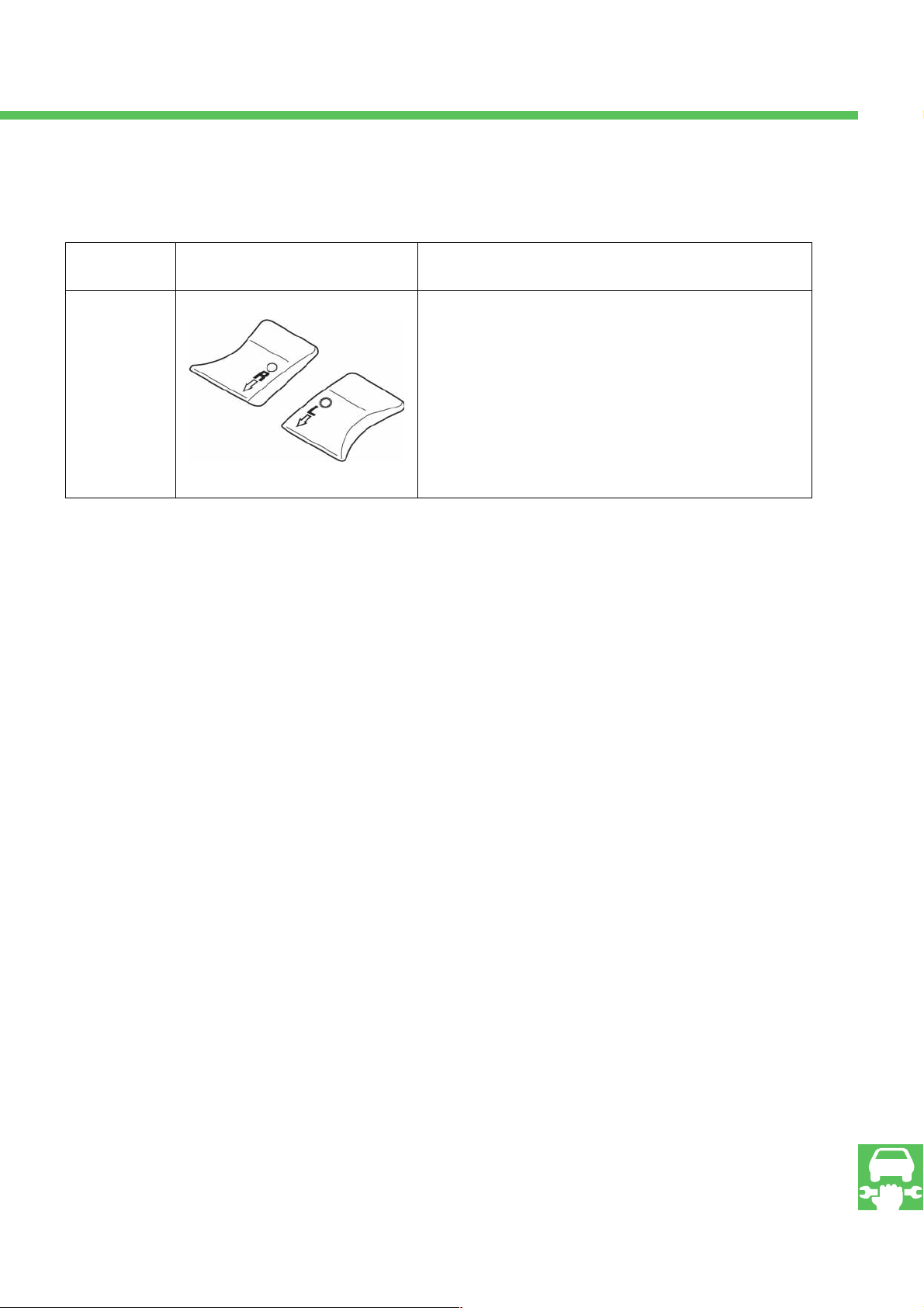
Tool No. Figure Designation and use
T 10311 Wing underlay
The wing underlays are required when removing and installing
the gearbox. They serve as underlays for support T 10222 A and
its adapters T 10222 A/8.
S338_137
Service
55
Page 56
338
© VOLKSWAGEN AG, Wolfsburg
All rights and technical changes reserved.
000.2811.53.20 Technical status 01.2005
Vol k swage n AG
Service Training VK-21
Brieffach 1995
D-38436 Wolfsburg
❀ This paper has been manufactured from cellulose bleached without the use of chlorine.
 Loading...