


CD 4506


C
D

BEFORE YOU START ....
Thank you for purchasing our product which has been designed and manufactured to the highest
standards and subjected to rigorous testing.
Please read this information carefully and follow the all instraction outlined below.This will ensure the
reliable operationand long service life of your radio. Keep this manual handy in your car for future
reference.
This manual covers the following models: CD4506 ,CD4526X,CD4626X
The main differences as the below chart:
Features: CD4506 CD4526X CD4626X
Housing Colour black silver-black silver
Key Colour orange green / orange green / orange
(switchable) (switchable)
Display Colour orange multicolour multicolour
Max. Power Output [W] 4 x 40 4 x 40 4 x 5 0
Sinus Power Output [W] 4 x 19 4 x 19 4 x 22
MP3 & WMA (vers. 9 or lower) • •
Line Out [Channels] - 2 4
CD-Changer Control • •
Telephone - Input - • •
OEM Remote Control Interface • • •
EDI - Interface - - •
ENVIRONMENT
This booklet is printed on low-chlorine recyclable paper.
IMPORTANT
This device has been designed and produced according to applicable Safety Regulations. Please
read carefully the instruction manual and use the device as intended.
CONTENTS PAGE
TECHNICAL DATA......... ....................................................................................................... 5
INSTALLATION ...................................................................................................................... 5
PREPARATION ...................................................................................................................... 5
MOUNTING ........................................................................................................................... 7
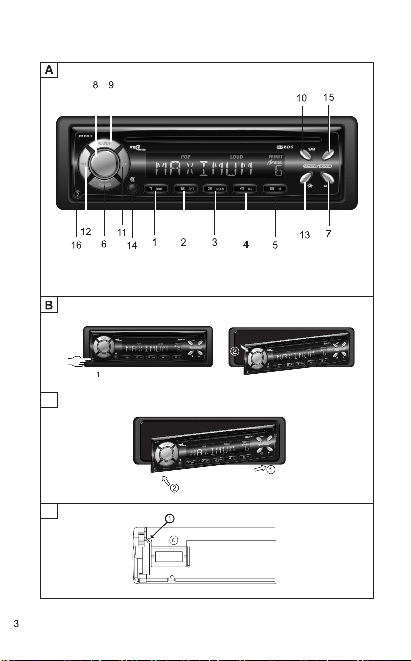
FRONT PANEL PRESENTATION ......................................................................................... 8
SECURITY ............................................................................................................................. 9
AUDIO .................................................................................................................................... 9
RADIO .................................................................................................................................. 10
RADIO DATA SYSTEM (RDS) ON FM............................................................................... 10
CD/MP3/CD CHANGER PLAYER ....................................................................................... 11
SPECIAL FUNCTIONS ........................................................................................................ 12
SETUP.................................................................................................................................. 13
TROUBLE SHOOTING....................................................................................................... 16
* Depending on version
4

TECHNICAL DATA
Following data is applied for CD4506,
CD4526X, CD4626X
• Temperature Range: -20°C ~ +75°C.
• Power Supply:
- 12 V DC, - at GND.
- Voltage Range: +10.5V~ +16 V.
- Current Consumption:
- About 1 A (about 0.1 A in off state)
• Dimensions (w x h x d ): DIN Housing,180 x
51 x 160 mm .
Warning:
- To prevent short-circuiting, disconnect the
negative car battery terminal until the set has
been mounted and connected (fig.1 See
separate installation card).
- Only trained specialists may install the unit.
- Always observe correct assignment of vehicle
connections. Incorrect assignment of the
connections may lead to damage of the unit or
vehicle electrical system/electronics.
- Observe automotive industry quality standards.
- Fire hazard! When drilling, care must be taken
not to damage concealed wiring harnesses, the
fuel tank and fuel lines.
- Never drill into supporting or safety-relevant
body parts.
INSTALLATION
Connection in vehicles equipped with
standard ISO connectors:
The radio may be installed without major
preparation in vehicles equipped with ISO
standard connectors. Some signals may have to
be adapted or connected to the ISO connectors
(see separate installation card).
Connection in vehicles without standard ISO
connectors:
For vehicles with different connection
requirements, ask your dealer for an adapter
cable. If no adapter cable is available for your
vehicle, connect the radio as described (see
separate installation card).
PREPARATION
Voltage and polarity: The set must be
connected to a 12V car battery with negative
terminal to earth (car chassis). Installation in
vehicles not fulfilling these requirements could
result in malfunction, damage or fire.
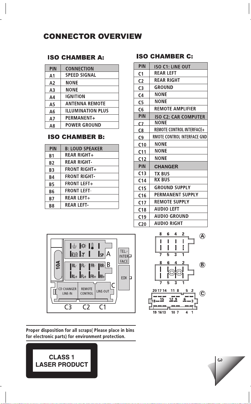
CONNECTOR A (fig.2)
Power supply connections
• A7 : Connect to a permanent 12V supply.
This is the main power supply. Ensure this
connection can handle a current of 10A.
• A4 : Connect to a switched 12Vsupply
(switched on/off by car ignition).
• A8: Connect to earth (car chassis).
This connection set up will enable you to make
full use of the ON/OFF LOGIC function of this set
limiting the use of the set to 1 hour after removal
of the ignition key. If this feature does not appear
to be functioning as expected you may require
an adaptor cable.
Optional connections: (fig. 2)
•SDVC (Speed Dependant Volume Control):
Intelligent volume control which automatically
adjust the volume depending on your car's
speed.
- Connect pin A1 to a signal from the
speedometer of your car. Some cars are
already prepared for it , please consult your
dealer.
- To activate the SMART volume function, see
SPECIAL FUNCTIONS, page 11.
• Electronic antenna/Motorised antenna
Connect pin A5 to the power supply for an
electronic antenna or the control wire for the
relay of an automatic motorised antenna.
Do not use this connection for the supply
lead of the aerial motor!
CONNECTOR B (fig.3)
Loudspeakers (use 4 ohm loudspeakers
only)
• Do not connect any of the loudspeaker leads
to earth or directly to a booster/amplifier without
high level input or via an external fader! You
can connect the loudspeaker leads directly to
an amplifier with high level input.
•Connecting 4 loudspeakers (see separate
installation card).
:
* Depending on version
5
 Loading...