


CD 2604 MP3X
User manual
Mode d’emploi
Bedienungsanleitung
Gebruiksaanwijzing
Istruzioni d’uso
Instrucciones de manejo
Modo de emprego
Bruksanvisning
Betjeningsvejledning
Käyttöohje
www.vdodayton.com

pg3_class1.p65 |
1 |
6/12/02, 10:23 AM |
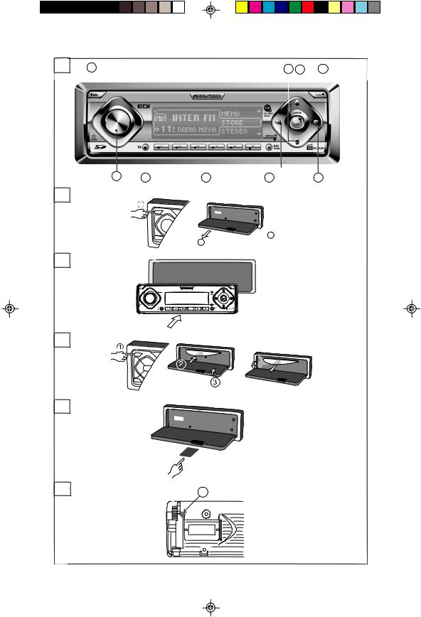
A |
2 |
7 |
8 |
9 |
|
1 |
3 |
4 |
5 |
6 |
B
 2
2
3
C
D
E
|
SD/ |
|
MMC |
F |
1 |
3

This page is a blank page.
4

INTRODUCTION
BEFORE STARTING
Thank you for purchasing this product which has been designed and manufactured according to applicable Safety Regulations, following the highest standards and subjected to rigorous testing. Please familiarise yourself with the device by reading carefully this instruction manual. Use the device as intended, then keep this manual handy in your car for future reference.
ENVIRONMENT
This booklet is printed on low-chlorine recyclable paper.
PREVENTIVE MAINTENANCE
To ensure good connection between the set and the detachable front, it is advisable to clean the connectors with a cotton swab
slightly moistened with cleaning fluid or alcohol periodically.
CONTENTS
INTRODUCTION . . . . . . . . . . . . . . . . . . . . . . 5
BEFORE STARTING . . . . . . . . . . . . . . . . . . . 5 ENVIRONMENT . . . . . . . . . . . . . . . . . . . . 5 PREVENTIVE MAINTENANCE . . . . . . . . 5
INSTALLATION. . . . . . . . . . . . . . . . . . . . . . . . 5 PREPARATION . . . . . . . . . . . . . . . . . . . . . 5 CONNECTORS . . . . . . . . . . . . . . . . . . . . . 5 SECURITY . . . . . . . . . . . . . . . . . . . . . . . . 8 HOME PAGE . . . . . . . . . . . . . . . . . . . . . . . . . 8 SETUP . . . . . . . . . . . . . . . . . . . . . . . . . . . 9
AUDIO . . . . . . . . . . . . . . . . . . . . . . . . . . . 14
TUNER . . . . . . . . . . . . . . . . . . . . . . . . . . 15 CD/MP3 Player . . . . . . . . . . . . . . . . . . . . 18 CD/MP3/DVD Changer . . . . . . . . . . . . . . 20 TELEPHONE. . . . . . . . . . . . . . . . . . . . . . 21
AUXILIARY . . . . . . . . . . . . . . . . . . . . . . . 23
SD/MMC PLAYBACK
(for CD and MP3 function). . . . . . . . . . . . 23 CAR COMPUTER . . . . . . . . . . . . . . . . . . 24 SPECIAL FUNCTIONS . . . . . . . . . . . . . . . . 24 CONFIGURATION. . . . . . . . . . . . . . . . . . 24 TROUBLESHOOTING . . . . . . . . . . . . . . . . . 25
INSTALLATION
If your car is equipped with ISO connectors, simply insert them in the connectors of the car radio. If not, you can use an adaptor cable
(Refer to the table on the separate installation card). Ensure all cables are installed so that they cannot be damaged by sharp edges or moving parts.
PREPARATION
The device must be connected to a 12V DC electrical system with a negative terminal earth
(car chassis).
 Warning: Installation that does not conform to these requirements may result in malfunction, damage or fire!
To avoid the risk of a short circuit during installation, disconnect the negative terminal of the battery until the set has been securely installed and connected. (see Installation card Fig.1).
CONNECTORS
Connector A** (see Fig.2)
a-Power Supply
1- Brown wire A8: connect to an earthing point on the car chassis.
2- Red wire A7: connect to a permanent 12V supply, main power supply for the set. Ensure that this connection can handle a current of 10A.
3- Yellow/red wire A4: connect to the switched
12V supply of the ignition.
Note: The ON/OFF logic function exists only when wire A7 (red) is connected to the permanent 12V supply.
b-Optional connections SMART Volume (


 ):
):
Intelligent volume control which automatically adjust the volume depending on your car’s speed. Connect pin A1 to a signal from the speedometer of your car. Some cars are already prepared for it (e.g. VW & Vauxhall/Opel cars), please consult your dealer. If not, you may need a more detailed installation requiring extra equipment to enable your car to become compatible.
5

 This can only be accomplished by persons familiar with automotive electrical and mechanical systems.
After connection, see “SPECIAL FUNCTIONS” for calibration procedure.
Electronic or Motorised Antenna
Connect pin A5 to the power supply for an electronic antenna or the control wire for the relay of an automatic motorised antenna.
 Do not use this connection for direct power supply to the antenna motor.
Connector B**
Loudspeakers (use 4 ohm loudspeakers only)
Do not connect any of the loudspeaker leads to earth or directly to a booster/amplifier without high level input or via an external fader! You can connect the loudspeaker leads directly to an amplifier with high level input:
Connecting 4 loudspeakers: |
|
|
Left (+) |
Front |
Rear |
Green B5 |
White B7 |
|
Left (-) |
Green/black B6 |
White/black B8 |
Right (+) |
Grey B3 |
Blue B1 |
Right (-) |
Grey/black B4 |
Blue/black B2 |
** For this accessory, contact your dealer.
Connector C
These specific set connectors belong to accessories sold separately (contact your dealer)
a-Yellow Connector C1 for line out (see Fig.4).
You can connect a power amplifier with 2 or 4 additional loudspeakers to this set using the RCA cable.
1- Use the red socket to right channel and white socket to left channel.
2- Use the blue wire (Pin 6) to Amplifier Remote On/Off.
b-Green Connector C2
Cables used for Car Computer control (temperature sensor), Steering Wheel remote control (see Fig.5). Please consult your dealer for the accessories and correct interface.
Temperature Sensor
You can connect a temperature sensor to the Pin 7 that will automatically give you a visual and audible signal when the outside temperature drops below 3°C. Use the Car Computer menu to activate/deactivate this feature.
 Warning: The temperature sensor is only an aid and cannot be used to determine exact road conditions.
You are entirely responsible for deciding whether it is safe to continue driving.
Wired Remote Control
Use the Pins 8 & 9 to connect wired remote control accessories.
c-Blue Connector C3 (MP3/DVD changer)
Cable used for CD, MP3 or DVD changer are come with changer. (see Fig.6).
Connector D
These specific set connectors belong to accessories sold separately (contact your dealer)
a-Connector D1
You can connect our Hands-free Phone Kit (available separately) via this connector (Fig7). With this accessory, the battery of your mobile phone could be charged, and the audio outputof the mobile phone can be played through the car loudspeakers.
Check with your dealer for more details about this accessory.
Telephone In
If you are using your own car kit please consult your dealer for the appropriate interface.
Telephone Mute
Use this input (pin 5) or the TEL_MUTE pink wire to connect your telephone mute signal. Or you can connect the telephone mute signal
from the phone to the pink wire of the headunit. Note : Before using your telephone, set the phone system and configure its appropriate detection level in the SETUPMenu.
b-Connector D3 (fig. 8)
- External Remote Display
You can show the content of headunit on
a specific car remote display via connector D3. Contact your dealer for an ‘EDI Box’ of the specific car which is sold separately.
- External Remote Control
You can connect an infra red remote eye (available separately) via D3 to remote control the headunit.
Audio In
You can connect external audio equipments via
Aux-in RCA cables.
Red wirefor Right Channel
White wirefor Left Channel input.
Rear Seat mute
Connect the external device (eg. DVD player) input to the ‘Rear Seat mute wire’ (Blue) to mute the rear speaker sound from the head unit.
6

MOUNTING
METAL SLEEVE (fig. 11 )
Install the metal sleeve (dimension 182x53 mm) in the dashboard. For optimal performance of the CD player, the metal sleeve should be positioned horizontally (between -10 and +30).
Fix metal sleeve into place by pressing the metal tags outwards using a screwdriver.
CONNECTING THE RADIO (fig. 9)
-Ensure the battery is disconnected.
-Insert aerial plug E into aerial socket (good reception is only possible with a good aerial).
Fix antenna adaptor if needed. Use hook (J) on back of set to secure fixing.
-Insert power supply connector A into socket A’.
-Insert loudspeaker connector B into socket B’.
-(Optional) Remove the protective cover from socket C’.
-(Optional) Insert the yellow line-out connector C1 into socket C1’.
-(Optional) Insert the blue CD changer connector C3 into socket C3’.
-(Optional) Insert the green connector C2 into socket C2’.
The green connector slides between the yellow connector C1 and the blue connector C3.
You need at least one of these connections to keep C2 in place.
MOUNTING RADIO
This radio can be properly installed either from conventional Front Mounting or Rear Mounting.
FRONT MOUNTING
-Slide the radio into the metal sleeve until the springs at either side of the radio snap
into the openings of the sleeve. (fig.14).
-Finally reconnect the negative car battery terminal (fig. 15).
REMOVING RADIO (using the two U- brackets supplied)
-Remove the trimplate around the front panel (fig. 13).
-Insert both U-brackets into the holes on the front of the set until they lock. Pull out the radio (fig. 14)
REAR MOUNTING (fig. 13)
-Remove the trim plate around the front panel and the side springs.
-Select a position where the screw holes of
the mounting bracket and the screw holes of the radio become aligned and tighten the screws at 2 places on each side.
-Only use M5 screws that are not longer than 6mm.
REPLACING THE FUSE (fig. 10)
-Replace with a 10A blade-type fuse. The new fuse must be of exactly this value and type otherwise the set will not be adequately protected. Ignoring this procedure may lead to damage to the set, which will invalidate the guarantee.
INTERFERENCE SUPPRESSION
-Most modern cars have sufficient interference suppression. If you experience interference generated by the car, consult your garage.
FRONT PANEL PRESENTATION
For illustration, see page 3, figure A.
1. PWR ............. |
Short press: Switch on; mute / |
|
demute (when set is on) |
|
Long press: Switch off |
|
Rotary Knob: Volume up / down |
2.REL ................ Flip down the detachable panel.
3.TA ................. Traffic Announcement
4.1 2 3 4 5 6 ..... Short press: Recall preset 1, 2,
|
|
3, 4, 5 or 6 (Tuner) |
|
|
Long press: Enter preset store |
|
|
mode (Tuner) |
5. ESC/HOME ..... |
Short press: Exit from current |
|
|
|
function/menu; Go to main |
|
|
source menu |
6. |
/ ............. |
Short press: Scroll through list |
|
|
of features; |
|
|
Search low / higher frequency |
|
|
(Tuner); |
|
|
Next / previous track (CD / MP3) |
7. |
/ ............. |
Short press: Scroll through list |
|
|
of features; |
|
|
Next / previous Directory (MP3); |
|
|
Next / previous 5 tracks (CD) |
8. OK ................ |
Short press: To enter menu; To |
|
|
|
activate function; To select |
|
|
feature. |
9. DISP ............. |
Short press: Display mode |
|
7

SECURITY
FRONT
REMOVING THE FRONT
1- Press the REL key.
2- Pull the front towards you. Follow the diagram mounted on the back of the detachable unit.
3- Take the detachable front with you when you leave the car.
4- Keep the front in its protective cover.
REPLACING THE FRONT
1- Put the left side of the front into the socket of the set.
2- Push the right side of front into place until it clicks into position.
Note 1 : If you hear a warning signal, the front is not properly replaced.
Note 2 : To ensure good connection between the set and the detachable unit, it is advisable to clean frequently the connections with a cotton swab from time to time.
LOCKING THE DETACHABLE FRONT
The detachable front can be locked by a D2 x
10 screw.
-Remove the trim plate
-Flip down the detachable front.
-Insert a D2 x 10 screw (inside the accessories bag) in position (1).
WARNINGS
Warning LED
When the engine is switched off and the front is removed, the warning LED flashes.You can switch off the warning LED (see SETUP menu,
Warning LED function).
IDENTIFICATION NUMBER
The set has a unique identification number (stated on the ‘Security card’).This card is required as a proof of ownership when the set is stolen, when the detachable front is lost or when requesting service.
HOME PAGE
Switching On/Off
•Short press (left) rotary knob to switch on the set.
•Long press rotary knob for more than 2 seconds to switch off the set.
SELECTING A SOURCE
Your car radio is designed for different types of sources. You can view the source menu by long or short press on the HOME/ESC key (depends on which level of source view you are currently in).
>TUNER
>CD/MP3
>CD/MP3/DVD CHANGER
>TELEPHONE
>AUXILIARY IN
>SD/MMC
>CAR COMPUTER
>SETUP
>SOUND
Press OK to activate the selected source.
VOLUME
Please make sure you can still hear the traffic
(horns, sirens..….)
-Turn the volume knob to adjust the volume.
The volume automatically increase or decrease if the SMART Volume connection
has been installed and selected (See
Installation).
Note : You can adjust the start-up volume. When the start-up volume is set to maximum level, it may be extremely loud when you switch on the set. See ‘SETUP’, option ‘START VOL’.
Mute
•Press Power rotary knob to mute/demute the sound when the set is switched on.
Note: You can set the mute level to SILENT, -20dB, -12dB or -6dB.
8
 Loading...