


Tripp lite PDUMH20ATNET, PDUMH20HVAT, PDUMH20AT, PDUMH20HVATNET, PDUMH15AT User Manual
...Warranty |
|
|
chance |
||||
|
for |
product! |
|||||
Registrationonline |
a |
|
|||||
|
|
|
|
|
.com/warranty |
||
|
|
|
|
today |
Lite |
|
|
|
|
FREE |
Tripp |
|
|
||
Registerwin |
|
|
|
||||
|
.tripplite |
|
|
||||
|
a |
|
|
|
|
|
|
to |
www |
|
|
|
|
||
Owner’s Manual
PDUMH15AT, PDUMH15ATNET,
PDUMH20AT, PDUMH20ATNET,
PDUMH20HVAT, PDUMH20HVATNET
Switched/Metered Rack PDU with
Automatic Transfer Switch*
1. Important Safety Instructions |
2 |
2. Installation |
2 |
2.1 Mounting the PDU |
2 |
2.2 Connecting the PDU |
3 |
2.3 Networking the PDU |
5 |
2.4 Test and Configure |
7 |
3. Features |
8 |
4. Configuration and Operation |
10 |
4.1 Automatic Transfer Switch |
10 |
4.2 Remote Monitoring and Control |
11 |
5. Technical Support |
12 |
6. Warranty and Warranty Registration |
12 |
1111 W. 35th Street • Chicago, IL 60609 USA
www.tripplite.com/support
Copyright © 2010 Tripp Lite. All rights reserved. SmartOnline™ is a trademark of Tripp Lite.
201003110 93-2945_EN.indd 1 |
3/26/2010 1:24:05 PM |
1. Important Safety Instructions
SAVE THESE INSTRUCTIONS
This manual contains instructions and warnings that should be followed during the installation, operation, and storage of this product. Failure to heed these instructions and warnings may affect the product warranty.
•The PDU provides convenient multiple outlets, but it DOES NOT provide surge or line noise protection for connected equipment.
•The PDU is designed for indoor use only in a controlled environment away from excess moisture, temperature extremes, conductive contaminants, dust or direct sunlight.
•Do not connect the PDU to an ungrounded outlet or to extension cords or adapters that eliminate the connection to ground.
•The power requirement for each piece of equipment connected to the PDU must not exceed the individual outlet’s load rating.
•The total power requirement for equipment connected to the PDU must not exceed the maximum load rating for the PDU.
•Do not drill into or attempt to open any part of the PDU housing. There are no user-serviceable parts inside.
•Do not attempt to modify the PDU, including the input plugs and power cables.
•Do not attempt to use the PDU if any part of it becomes damaged.
•Do not attempt to mount the PDU to an insecure or unstable surface.
•Never attempt to install electrical equipment during a thunderstorm.
•Use of this equipment in life support applications where failure of this equipment can reasonably be expected to cause the failure of the life support equipment or to significantly affect its safety or effectiveness is not recommended. Do not use this equipment in the presence of a flammable anesthetic mixture with air, oxygen or nitrous oxide.
2.Installation
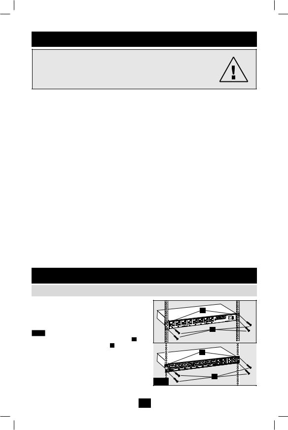
2.1 Mounting the PDU |
|
|
The PDU supports 1U Rack configurations. |
|
|
Note: The user must determine the fitness of hardware and |
B |
|
procedures before mounting. The PDU and included hardware are |
||
|
||
designed for common rack and rack enclosure types and may not |
|
|
be appropriate for all applications. Exact mounting configurations |
|
|
may vary. |
|
|
2.1.1 1U Rack Mounting: Attach the PDU to |
A |
|
PDUMH15AT, PDUMH15ATNET, |
||
the rack by inserting four user-supplied screws A |
||
PDUMH20AT, PDUMH20ATNET |
||
through the PDU mounting brackets B and into |
|
|
the mounting holes of the rack rail as shown. |
B |
|
2.1.1 |
A |
|
PDUMH20HVATNET |
2
201003110 93-2945_EN.indd 2 |
3/26/2010 1:24:06 PM |
2.Installation (continued)
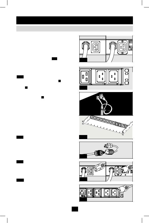
2.2Connecting the PDU
The PDU includes two AC power inputs: Primary |
|
Primary Input (120V Models) |
||
and Secondary. The Primary input cord is |
|
|
|
|
permanently attached to the rear of the PDU |
|
|
|
|
(120V models). |
|
|
|
|
IEC-320-C14 inlet is used for the primary input |
|
|
|
|
of the 230V model. |
|
|
|
|
The Secondary input cord is detachable and |
|
PDUMH15AT |
|
PDUMH20AT |
connects to the IEC power inlet 2.2.1 at the rear |
2.2.1 |
|
||
PDUMH15ATNET |
|
PDUMH20ATNET |
||
of the PDU (PDUMH15AT, PDUMH15ATNET - |
|
Primary Input (230V Model) |
||
IEC-320-C14 inlet; PDUMH20AT, |
|
|||
PDUMH20ATNET, PDUMH20HVAT, |
|
|
|
|
PDUMH20HVATNET - IEC-320-C20 inlet). |
|
Unswitched Outlets |
SecondaryInput |
PrimaryInput |
1. Form a loop in the Secondary cord A and |
|
|||
2.2.2 To connect the Secondary input cord: |
|
|
|
|
secure the juncture of that loop to the Primary |
|
|
|
|
cord B with a zip tie. Be sure the zip tie is |
2.2.1 230V PDUMH20HVAT & PDUMH20HVATNET |
|||
secured around the Secondary and Primary |
|
|
|
|
cords, as well as through the loop created in |
|
|
|
|
the Secondary cord C . (See diagram). Note: |
|
|
A |
|
Give the cord as much slack as possible |
|
|
|
|
|
|
|
|
|
between the loop and the cord’s outlet. |
|
B |
|
|
2. On Models PDUMH20HVAT and |
|
|
|
|
PDUMH20HVATNET, both cords should be |
|
C |
|
|
tied to the Cable Retention Tray. (See |
|
|
|
|
diagram). |
|
|
|
|
3. Once you’ve secured the two cords together |
|
|
|
|
and ensured that the Secondary cord has a |
|
|
|
|
comfortable amount of slack, insert the |
|
|
|
|
Secondary cord outlet into the IEC power inlet. |
|
|
|
|
2.2.3 Connect Input Plug Adapters (Optional |
2.2.2 |
|
|
|
- Models PDUMH20AT, PDUMH20ATNET |
|
|
|
|
Only): The PDU includes two adapters that |
|
|
|
|
convert one or both of the L5-20P input plugs to |
|
|
|
|
5-20P input plugs. Connecting the adapters is |
|
|
|
|
optional. The PDU will function normally without |
2.2.3 |
|
|
PDUMH20AT, |
connecting the adapters. |
|
|
PDUMH20ATNET |
|
2.2.4 Connect Secondary Input Cord to PDU: |
|
|
|
|
Although the PDU will operate without |
|
|
|
|
connecting the Secondary input cord, the |
|
|
|
|
Secondary input is required for the PDU's |
|
|
|
|
Automatic Transfer Switch function. |
|
|
|
|
2.2.5 C19-C20 Cables (optional: Models |
2.2.4 |
PDUMH15AT, |
|
PDUMH20AT, |
PDUMH15ATNET |
|
PDUMH20ATNET |
||
PDUMH20HVAT and PDUMH20HVATNET |
|
|
|
|
only): The PDU includes two C19 to C20 |
|
|
|
|
interconnection cables for the two primary and |
|
Unswitched Outlets |
SecondaryInput |
Primary |
secondary inlets, which may be used to connect |
|
|||
|
|
|
|
|
to upstream UPS sources. Alternately, the user |
2.2.5 |
|
|
|
can supply IEC cables fitted with country-specific |
PDUMH20HVAT & PDUMH20HVATNET |
|||
plugs. |
|
|
|
|
3
201003110 93-2945_EN.indd 3 |
3/26/2010 1:24:08 PM |

2.Installation (continued)
2.2Connecting the PDU (continued)
2.2.6 Connect PDU Input Plugs: (See the |
|
|
|
|
Configuration and Operation section for more |
|
|
|
|
information.) Connect the Primary input plug A to a |
|
|
|
|
preferred source of grounded 120V/230V AC power, |
|
|
|
|
such as a SmartOnline™ UPS System. The UPS |
|
A |
|
|
system must not share a circuit with a heavy |
|
|
|
|
electrical load (such as an air conditioner or |
|
|
|
|
refrigerator). Under normal operating conditions, |
|
|
B |
PDUMH15AT, |
the PDU will distribute AC power from the Primary |
|
|
PDUMH15ATNET |
|
|
|
|
|
|
input source. Connect the Secondary input plug B |
|
|
|
|
to an alternative source of grounded 120V/230V AC |
|
|
|
|
power, such as a redundant SmartOnline UPS |
|
|
|
|
System. The UPS system must not share a circuit |
|
|
|
|
with a heavy electrical load (such as an air |
|
|
|
|
conditioner or refrigerator). Do not plug the |
|
|
|
|
Secondary input into the same power source as the |
|
|
A |
PDUMH20AT, |
Primary input. The PDU will distribute AC power |
|
|
||
|
|
|
PDUMH20ATNET |
|
from the Secondary input only if the Primary input |
|
|
|
|
becomes unavailable. |
|
|
|
|
Note: Immediately after the PDU is connected to live AC |
|
|
B |
|
power, you may notice a series of soft clicking sounds emitted by |
|
|
|
|
electrical relays within the PDU. The relays may also click |
|
|
|
|
occasionally during the operation of the PDU. This is normal. |
|
|
|
|
2.2.7 Selecting Input Voltage Range (optional: |
|
|
|
|
Models PDUMH20HVAT & |
|
|
|
|
PDUMNH20HVATNET only): This model has two |
|
|
|
|
selectable nominal input voltage ranges: 200V-208V |
|
|
|
|
(“LO”) and 220V-240V (“HI”). Press the switch |
|
|
A |
|
next to the display to toggle the nominal voltage |
|
|
PDUMH20HVAT & |
|
setting to the desired “HI” or “LO” range. This |
|
|
|
|
setting adjusts the voltage ranges for the primary |
|
|
|
PDUMH20HVATNET |
|
|
|
|
|
and secondary inputs. The display will indicate “HI” |
|
|
Unswitched Outlets |
|
or “LO” for five seconds. |
|
|
|
|
2.2.8 Connect Equipment to PDU: Do not |
|
|
|
B |
exceed the load rating of the PDU. The total |
|
|
|
|
|
|
|
|
|
electrical current used by the PDU will be displayed |
|
|
|
|
on the digital meter in amperes. Each outlet includes |
2.2.6 |
|
|
|
a green LED that illuminates when the outlet is |
|
|
|
|
receiving AC power. |
|
|
|
|
PDUMH20AT |
PDUMH20ATNET |
PDUMH20HVAT & PDUMH20HVATNET |
||
|
|
|
|
|
|
|
|
|
|
|
|
|
|
|
|
|
|
|
|
|
|
|
|
|
|
|
|
|
|
|
|
|
|
|
|
2.2.8 |
PDUMH15AT |
PDUMH15ATNET |
|
|||||
4
201003110 93-2945_EN.indd 4 |
3/26/2010 1:24:11 PM |
 Loading...