


Tripp Lite PDU3MV6L2120, PDU3MV6L2120LV, PDU3MV6L2130, PDU3MV6H50, PDU3MV6H50A Owner's Manual
...Owner’s Manual
3-Phase Metered and Basic
Power Distribution Units
PDU3MV6L2120 |
PDU3MV6H50A |
PDU3V6H50A |
(Series Number: AGPD8414) |
(Series Number: AGPD8417) |
(Series Number: AGPD8417) |
PDU3MV6L2120LV |
PDU3XMV6G20 |
PDU3V6L2120LV |
(Series Number: AGPD8414) |
(Series Number: AGPD8420) |
(Series Number: AGPD8414) |
PDU3MV6L2120B |
PDU3XMV6L2220 |
PDU3V6L2130 |
(Series Number: AGPD8414) |
(Series Number: AGPD8420) |
(Series Number: AGPD8415) |
PDU3MV6L2130 |
PDU3MV6L2130A |
PDU3XV6G20 |
(Series Number: AGPD8415) |
(Series Number: AG-00E3) |
(Series Number: AGPD8420) |
PDU3MV6H50 |
PDU3V6H50 |
|
(Series Number: AGPD8416) |
(Series Number: AGPD8416) |
|
Important Safety Insructions |
2 |
Installation |
3 |
Digital Load Meter |
6 |
Features |
7 |
Service |
8 |
Warranty and Product Registration |
9 |
Español |
10 |
Français |
19 |
Pyccкий |
28 |
WARRANTY REGISTRATION
Register your product today and be automatically entered to win an ISOBAR® surge protector in our monthly drawing!
tripplite.com/warranty
1111 W. 35th Street, Chicago, IL 60609 USA • tripplite.com/support
Copyright © 2020 Tripp1Lite. All rights reserved.
20-09-045-933145.indb 1 |
10/7/2020 11:55:08 AM |

Important Safety Instructions
SAVE THESE INSTRUCTIONS
This manual contains instructions and warnings that should be followed during the installation, operation, and storage of this product. Failure to heed these instructions and warnings may affect the product warranty.
•The PDU provides convenient multiple outlets, but it DOES NOT provide surge or line noise protection for connected equipment.
•The PDU is designed for indoor use only in a controlled environment away from excess moisture, temperature extremes, conductive contaminants, dust or direct sunlight.
•Do not connect the PDU to an ungrounded outlet or to extension cords or adapters that eliminate the connection to ground.
•The power requirement for each piece of equipment connected to the PDU must not exceed the individual outlet’s load rating.
•The total power requirement for equipment connected to the PDU must not exceed the maximum load rating for the PDU.
•Do not drill into or attempt to open any part of the PDU housing. There are no user-serviceable parts inside.
•Do not attempt to modify the PDU, including the input plugs and power cables.
•Do not attempt to use the PDU if any part of it becomes damaged.
•Do not attempt to mount the PDU to an insecure or unstable surface.
•Use of this equipment in life support applications where failure of this equipment can reasonably be expected to cause the failure of the life support equipment or to significantly affect its safety or effectiveness is not recommended. Do not use this equipment in the presence of a flammable anesthetic mixture with air, oxygen or nitrous oxide.
•Never attempt to install electrical equipment during a thunderstorm.
•Keep indoor ambient temperature between 32°F and 104°F (0°C and 40°C).
•Connect the PDU to an outlet that is in accordance with your local building codes and that is adequately protected against excess currents, short circuits and earth faults.
•Do not attempt to open the PDU; there are no user-serviceable parts inside.
•The PDU must be installed by a qualified technician only.
•Install in accordance with National Electrical Codes. Be sure to use the proper over current protection for the installation, in accordance with the plug rating/equipment rating.
•The electrical sockets supplying power to the equipment shall be installed near the equipment and be easily accessible.
2
20-09-045-933145.indb 2 |
10/7/2020 11:55:08 AM |
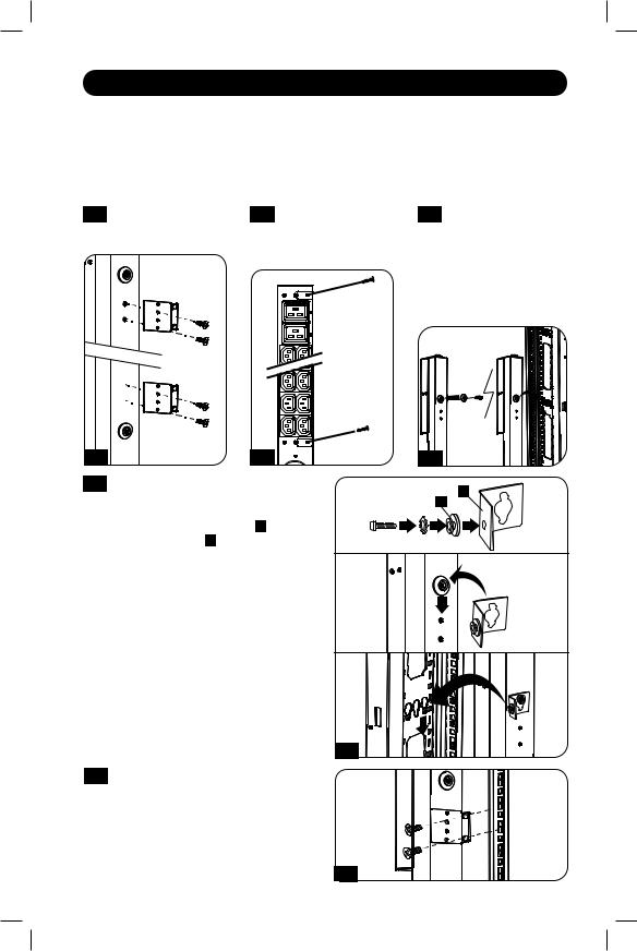
Installation
Mounting the PDU
Note: The illustrations may differ somewhat from your PDU model. Regardless of configuration, the user must determine the fitness of hardware and procedures before mounting. The PDU and included hardware are designed for common rack and rack enclosure types and may not be appropriate for all applications. Exact mounting configurations may vary. Screws for attaching the mounting brackets and cord retention shelf to the PDU are included. Use only the screws supplied by Tripp Lite, or their exact equivalent.
1-1 Attach the mounting |
1-2 (Optional) Attach the |
1-3 For toolless mounting, |
brackets to the PDU. |
cord retention |
position the PDU as |
|
bracket(s) to the PDU. |
desired in the rack |
|
|
enclosure, align the |
|
|
buttons with the rack |
|
|
mounting slots, and |
|
|
slide the PDU into |
|
|
position. |
1-1
1-4
1-2
To install the PDU with its outlets facing the rear of the rack, use the included PDUMVROTATEBRKT accessory. First, attach the mounting button A to the V-shaped bracket B using the included screw and washer. Then, use the button-mount slot to attach the bracket to the PDU and the mounting button to attach the PDU to the rack. The bracket effectively repositions the mounting brackets, allowing for the PDU outlets to face the rear of the rack.
1-3
B
A
1-4
1-5 If your PDU cannot be mounted |
|
using the toolless mounting option, |
|
the mounting brackets can be used. |
|
Attach the PDU to a vertical rail in |
|
your rack or rack enclosure. (Use the |
|
mounting hardware that came with your |
|
rack or rack enclosure to attach the |
1-5 |
mounting brackets to the rail.) |
|
|
3 |
20-09-045-933145.indb 3 |
10/7/2020 11:55:09 AM |

Installation
Connecting the PDU
2-1 Each model is equipped with 1 of 5 different input plugs.
IEC 309 16A Red |
Hubbell CS8365C |
|
L21-30P |
|
L21-20P |
L22-20P |
|||||
(3P + N + E) |
|
|
|
|
|
|
|
|
|
|
|
|
|
|
|
|
|
|
|
|
|
|
|
|
|
|
|
|
|
|
|
Balanced |
|
|
|
|
|
|
|
|
|
|
|
Output |
|
|
|
|
|
|
Max |
|
Input |
|
Output |
Current |
Cord |
|
|
Model # |
|
Input Plug |
Amps |
|
Voltage |
|
Voltage |
per Phase |
Length |
Outlet Types |
Breakers |
|
|
|
|
|
|
|
|
|
|
|
|
|
|
|
|
|
|
|
|
|
|
36 x C13 |
|
PDU3MV6L2120 |
|
|
|
|
|
|
208V/ |
|
6 ft. |
(208V)6 x |
|
|
L21-20P |
16A |
|
208V |
|
9.2A |
(1.8 m) |
C19 (208V)6 |
N/A |
||
(AGPD8414) |
|
|
|
120V |
|||||||
|
|
|
|
|
|
|
|
x 5-15/20R |
|
||
|
|
|
|
|
|
|
|
|
|
|
|
|
|
|
|
|
|
|
|
|
|
(120V) |
|
|
|
|
|
|
|
|
|
|
|
|
|
|
|
|
|
|
|
|
|
|
|
36 x C13 |
|
PDU3MV6L2130 |
|
|
|
|
|
|
208V/ |
|
6 ft. |
(208V)6 x |
(3) 20A 2-POLE |
(AGPD8415) |
|
L21-30P |
24A |
|
208V |
|
120V |
13.9A |
(1.8 m) |
C19 (208V)6 |
|
|
|
|
MAGNETIC |
||||||||
|
|
|
|
|
|
|
|
|
|
x 5-15/20R |
|
|
|
|
|
|
|
|
|
|
|
|
|
|
|
|
|
|
|
|
|
|
|
(120V) |
|
|
|
|
|
|
|
|
|
|
|
|
|
|
|
|
|
|
|
|
|
|
|
36 x C13 |
|
PDU3V6L2130 |
|
|
|
|
208V/ |
|
208V/ |
|
6 ft. |
(208V)6 x |
(3) 20A 2-POLE |
(AGPD8415) |
|
L21-30P |
24A |
|
120V |
|
120V |
13.8A |
C19 (208V)6 |
||
|
|
|
(1.8 m) |
MAGNETIC |
|||||||
|
|
|
|
|
|
|
|
|
x 5-15/20R |
||
|
|
|
|
|
|
|
|
|
|
|
|
|
|
|
|
|
|
|
|
|
|
(120V) |
|
|
|
|
|
|
|
|
|
|
|
|
|
PDU3MV6L2130A |
|
|
|
|
200V- |
|
200V- |
|
6 ft. |
36 x C13 |
(3) 20A 2-POLE |
(AG-00E3) |
|
L21-30P |
24A |
|
|
13.9A |
9 x C19 |
||||
|
|
240V |
|
240V |
(1.8 m) |
MAGNETIC |
|||||
|
|
|
|
|
|
|
|
||||
|
|
|
|
|
|
|
|
|
|
|
|
PDU3V6H50 |
|
Hubbell |
|
|
|
|
|
|
6 ft. |
36 x C13 |
(3) 20A 2-POLE |
(AGPD8416) |
|
35A |
|
208V |
|
208V |
20.0A |
(208V) 9 x C19 |
|||
|
CS8365C |
|
|
(1.8 m) |
MAGNETIC |
||||||
|
|
|
|
|
|
|
|
|
|
(208V) |
|
PDU3MV6H50 |
|
Hubbell |
|
|
|
|
|
|
6 ft. |
36 x C13 |
(3) 20A 2-POLE |
(AGPD8416) |
|
35A |
|
208V |
|
208V |
20.0A |
(208V) 9 x C19 |
|||
|
CS8365C |
|
|
(1.8 m) |
MAGNETIC |
||||||
|
|
|
|
|
|
|
|
|
|
(208V) |
|
|
|
|
|
|
|
|
|
30A |
|
36 x C13 |
(2) 20A 2-POLE |
PDU3V6H50A |
|
|
|
|
|
|
|
(L1-L2) |
|
||
|
Hubbell |
|
|
|
|
|
6 ft. |
(208V)6 x C19 |
MAGNETIC(1) |
||
(AGPD8417) |
|
40A |
|
208V |
|
208V |
20A |
||||
|
CS8365C |
|
|
(1.8 m) |
(208V)3 x L6- |
30A 2-POLE |
|||||
|
|
|
|
|
|
|
(L2-L3, |
||||
|
|
|
|
|
|
|
|
|
30R (208V) |
MAGNETIC |
|
|
|
|
|
|
|
|
|
L3-L1) |
|
||
|
|
|
|
|
|
|
|
|
|
|
|
|
|
|
|
|
|
|
|
|
|
|
|
PDU3MV6H50A |
|
|
|
|
|
|
|
|
|
36 x C13 |
(2) 20A 2-POLE |
|
Hubbell |
|
|
|
|
|
|
6 ft. |
(208V)6 x C19 |
MAGNETIC(1) |
|
(AGPD8417) |
|
40A |
|
208V |
|
208V |
20.0A |
||||
|
CS8365C |
|
|
(1.8 m) |
(208V)3 x L6- |
30A 2-POLE |
|||||
|
|
|
|
|
|
|
|
||||
|
|
|
|
|
|
|
|
|
|
30R (208V) |
MAGNETIC |
|
|
|
|
|
|
|
|
|
|
|
|
PDU3V6L2120LV |
|
L21-20P |
16A |
|
208V/ |
|
120V |
9.2A |
6 ft. |
42 x 5-15/20R |
N/A |
(AGPD8414) |
|
|
120V |
|
(1.8 m) |
(120V) |
|||||
|
|
|
|
|
|
|
|
||||
|
|
|
|
|
|
|
|
|
|
|
|
PDU3MV6L2120LV |
|
L21-20P |
16A |
|
208V |
|
120V |
9.2A |
6 ft. |
42 x 5-15/20R |
N/A |
(AGPD8414) |
|
|
|
(1.8 m) |
(120V) |
||||||
|
|
|
|
|
|
|
|
|
|||
|
|
|
|
|
|
|
|
|
|
|
|
|
|
|
|
|
|
|
|
|
|
6 x L6-20R |
|
PDU3MV6L2120B |
|
L21-20P |
16A |
|
208V |
|
208V/ |
9.2A |
6 ft. |
(120V)21 x |
N/A |
(AGPD8414) |
|
|
|
120V |
(1.8 m) |
5-15/20R |
|||||
|
|
|
|
|
|
|
|
||||
|
|
|
|
|
|
|
|
|
|
(120V) |
|
|
|
|
|
|
|
|
|
|
|
|
|
|
|
IEC 309 |
|
|
360V- |
|
208V- |
|
6 ft. |
36 x C13 |
|
PDU3XV6G20 |
|
16A Red |
16A |
|
|
16.0A |
(208V)9 x C19 |
N/A |
|||
|
|
415V |
|
240V |
(1.8 m) |
||||||
|
|
(3P + N + E) |
|
|
|
|
|
|
|
(208V) |
|
4
20-09-045-933145.indb 4 |
10/7/2020 11:55:09 AM |

Installation
|
|
|
|
|
Balanced |
|
|
|
|
|
|
|
|
|
Output |
|
|
|
|
|
|
Max |
Input |
Output |
Current |
Cord |
|
|
|
Model # |
Input Plug |
Amps |
Voltage |
Voltage |
per Phase |
Length |
Outlet Types |
Breakers |
|
PDU3XMV6G20 |
IEC 309 |
|
360V- |
208V- |
|
6 ft. |
36 x C13 |
|
|
16A Red |
16A |
16.0A |
(208V)9 x C19 |
N/A |
|||||
(AGPD8420) |
415V |
240V |
(1.8 m) |
||||||
|
(3P + N + E) |
|
|
|
|
|
(208V) |
|
|
PDU3XMV6L2220 |
|
|
360V- |
208V- |
|
6 ft. |
36 x C13 |
|
|
L22-20P |
16A |
16.0A |
(208V) |
N/A |
|||||
(AGPD8420) |
415V |
240V |
(1.8 m) |
||||||
|
|
|
9 x C19 (208V) |
|
2-2 Connect the input plug to your facility’s compatible AC power source.
2-2 |
Some Models |
Will Vary. |
2-3
2-4
Connect your equipment’s input plugs to the appropriate outlets on the PDU.
Note: It is recommended that you do not connect a live load to the PDU. If the load you intend to connect has an ON/OFF switch, please turn the switch to OFF prior to connection.
Option 1 - Wire Retention Shelf Procedure (for PDU3MV6L2120, PDU3MV6L2120LV, PDU3MV6L2120B, PDU3MV6L2130, PDU3MV6H50, PDU3MV6H50A, PDU3XMV6G20 and PDU3XMV6L2220 models): If you attached the cord retention bracket(s), tie each equipment power cord to the retention bracket. Attach each cord to the retention shelf by looping the cord and securing it with one of the included cable ties A . Make sure each cord can be unplugged from the PDU without removing the cable tie.
Option 2 - Cord Retention Procedure (for PDU3MV6L2130A): Use the included C14 and C20 plastic sleeves to secure plugs to receptacles. Attach the sleeve to the plug, making sure that the pull tabs B remain outside the plug and that the fit is secure. To unplug equipment properly, use the pull tabs to remove the plug and sleeve from the receptacle.
A
2-3 |
2-4 |
B
2-4
20-09-045-933145.indb 5 |
10/7/2020 11:55:10 AM |
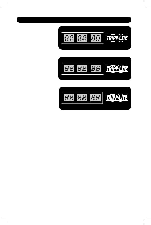
Digital Load Meter (Select Models Only)
Input Amps: The total aggregate current (in Amps) drawn by each of the PDU phases will be displayed independently by 1 of 3 digital meters.
Load Amps: The total aggregate current drawn (in Amps by the load bank associated with each phase
will be displayed independently by 1 of 3 digital meters.
INPUT (AMPS)
L1 |
L2 |
L3 |
(PDU3MV6L2120, PDU3MV6L2130, PDU3MV6L2120B)
LOAD (AMPS)
L1 |
L2 |
L3 |
(PDU3MV6L2120LV, PDU3XMV6G20, PDU3XMV6L2220)
LOAD (AMPS)
L1-L2 |
L2-L3 |
L3-L1 |
(PDU3MV6H50, PDU3MV6H50A, PDU3MV6L2130A)
6
20-09-045-933145.indb 6 |
10/7/2020 11:55:10 AM |
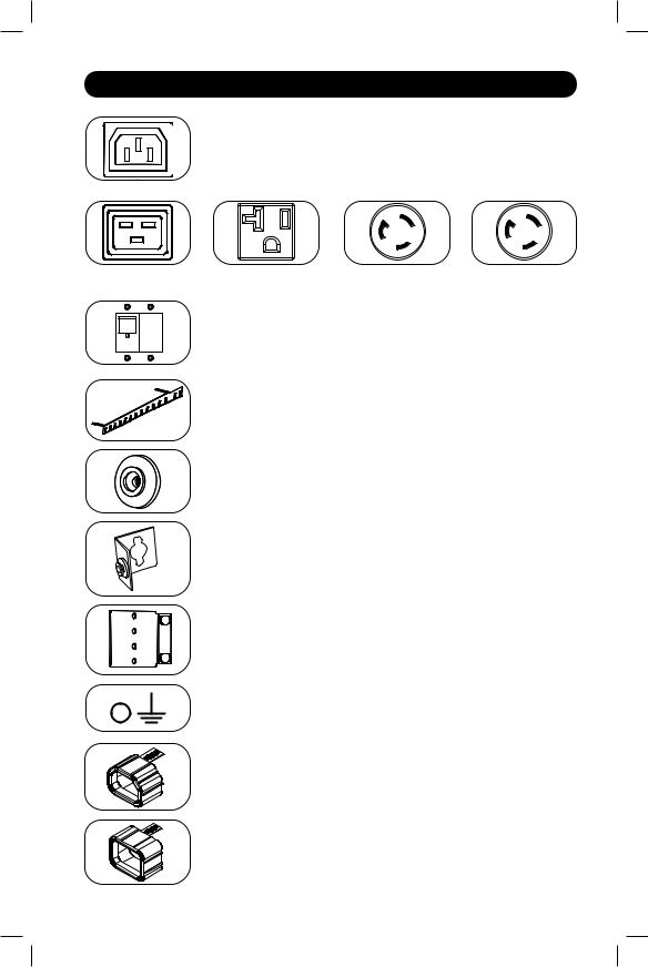
Features
Outlets: During normal operation, the outlets distribute AC power to connected equipment.
IEC-60320-C13
IEC-60320-C19 |
NEMA 5-15/20R |
20 amp (208V) |
30 amp (208V) |
|
|
NEMA L6-20R |
NEMA L6-30R |
Circuit Breaker (Select Models): Each phase has its own breaker. If the connected equipment load exceeds the Maximum Load Rating for that phase of the PDU, the circuit breaker will trip. Disconnect excess equipment and allow the breaker to cool before resetting the breaker.
Cord Retention Bracket: Provides secure attachment points for connected equipment cords.
Mounting Buttons: Come pre-installed on the back side of the PDU and are used for toolless mounting. Note: Four additional mounting buttons are included for alternate rack styles.
PDUMVROTATEBRKT Mounting Accessory: Use these V-shaped brackets to mount the PDU with its outlets facing the rear of the rack.
Mounting Brackets: Use these brackets to mount the PDU in racks that are not compatible with toolless button mounting methods.
Ground Screw: Use this to connect any equipment that requires a chassis ground.
C14 Plug Sleeve: (Optional) Use the included C14 plastic sleeves to secure plugs to receptacles. Attach the sleeve to the plug, making sure that the pull tabs remain outside the plug and that the fit is secure. To unplug equipment properly, use the pull tabs to remove the plug and sleeve from the receptacle.
C20 Plug Sleeve: (Optional) Use the included C20 plastic sleeves to secure plugs to receptacles. Attach the sleeve to the plug, making sure that the pull tabs remain outside the plug and that the fit is secure. To unplug equipment properly, use the pull tabs to remove the plug and sleeve from the receptacle.
7
20-09-045-933145.indb 7 |
10/7/2020 11:55:11 AM |

Service
Your Tripp Lite product is covered by the warranty described in this manual. A variety of Extended Warranty and On-Site Service Programs are also available from Tripp Lite. For more information on service, visit tripplite.com/support. Before returning your product for service, follow these steps:
1.Review the installation and operation procedures in this manual to ensure that the service problem does not originate from a misinterpretation of the instructions.
2.If the problem continues, do not contact or return the product to the dealer. Instead, visit tripplite.com/support.
3.If the problem requires service, visit tripplite.com/support and click the Product Returns link. From here you can request a Returned Material Authorization (RMA) number, which is required for service. This simple on-line form will ask for your unit’s model and serial numbers, along with other general purchaser information. The RMA number, along with shipping instructions will be emailed to you. Any damages (direct, indirect, special or consequential) to the product incurred during shipment to Tripp Lite or an authorized Tripp Lite service center is not covered under warranty. Products shipped to Tripp Lite or an
authorized Tripp Lite service center must have transportation charges prepaid. Mark the RMA number on the outside of the package. If the product is within its warranty period, enclose
a copy of your sales receipt. Return the product for service using an insured carrier to the address given to you when you request the RMA.
8
20-09-045-933145.indb 8 |
10/7/2020 11:55:11 AM |

Warranty and Product Registration
2- YEAR LIMITED WARRANTY
Seller warrants this product, if used in accordance with all applicable instructions, to be free from original defects in material and workmanship for a period of 2 years from the date of initial purchase. If the product should prove defective in material or workmanship within that period, Seller will repair or replace the product, in its sole discretion. Service under this Warranty can only be obtained by your delivering or shipping the product (with all shipping or delivery charges prepaid) to: Tripp Lite, 1111 W. 35th Street, Chicago, IL 60609 USA. Seller will pay return shipping charges. Visit tripplite.com/support before sending any equipment back for repair.
THIS WARRANTY DOES NOT APPLY TO NORMAL WEAR OR TO DAMAGE RESULTING FROM ACCIDENT, MISUSE, ABUSE OR NEGLECT. SELLER MAKES NO EXPRESS WARRANTIES OTHER THAN THE WARRANTY EXPRESSLY SET FORTH HEREIN. EXCEPT TO THE EXTENT PROHIBITED BY APPLICABLE LAW, ALL IMPLIED WARRANTIES, INCLUDING ALL WARRANTIES OF MERCHANTABILITY OR FITNESS, ARE LIMITED IN DURATION TO THE WARRANTY PERIOD SET FORTH ABOVE; AND THIS WARRANTY EXPRESSLY EXCLUDES ALL INCIDENTAL AND CONSEQUENTIAL DAMAGES. (Some states do not allow limitations on how long an implied warranty lasts, and some states do not allow the exclusion or limitation of incidental or consequential damages, so the above limitations or exclusions may not apply to you. This Warranty gives you specific legal rights, and you may have other rights which vary from jurisdiction to jurisdiction).
WARNING: The individual user should take care to determine prior to use whether this device is suitable, adequate or safe for the use intended. Since individual applications are subject to great variation, the manufacturer makes no representation or warranty as to the suitability or fitness of these devices for any specific application.
PRODUCT REGISTRATION
Visit tripplite.com/warranty today to register your new Tripp Lite product.You’ll be automatically entered into a drawing for a chance to win a FREE Tripp Lite product!*
* No purchase necessary. Void where prohibited. Some restrictions apply. See website for details.
FCC Notice, Class A
This device complies with part 15 of the FCC Rules. Operation is subject to the following two conditions: (1) This device may not cause harmful interference, and (2) this device must accept any interference received, including interference that may cause undesired operation.
Note: This equipment has been tested and found to comply with the limits for a Class A digital device, pursuant to part 15 of the FCC Rules. These limits are designed to provide reasonable protection against harmful interference when the equipment is operated in a commercial environment. This equipment
generates, uses, and can radiate radio frequency energy and, |
if not installed |
and used in accordance |
|
with |
the instruction manual, may cause harmful interference |
to radio communications. Operation of |
|
this |
equipment in a residential area is likely to cause harmful |
interference in |
which case the user will |
be required to correct the interference at his own expense. The user must use shielded cables and connectors with this equipment. Any changes or modifications to this equipment not expressly approved by Tripp Lite could void the user’s authority to operate this equipment.
Regulatory Compliance Identification Numbers
For the purpose of regulatory compliance certifications and identification, your Tripp Lite product has been assigned a unique series number. The series number can be found on the product nameplate label, along with all required approval markings and information. When requesting compliance information for this product, always refer to the series number. The series number should not be confused with the marking name or model number of the product.
WEEE Compliance Information for Tripp Lite Customers and Recyclers (European Union)
Under the Waste Electrical and Electronic Equipment (WEEE) Directive and implementing regulations, when customers buy new electrical and electronic equipment from Tripp Lite they are entitled to:
• Send old equipment for recycling on a one-for-one, like-for-like basis (this varies depending on the country)
• Send the new equipment back for recycling when this ultimately becomes waste
Tripp Lite has a policy of continuous improvement. Specifications are subject to change without notice. Photos and illustrations may differ slightly from actual products.
1111 W. 35th Street, Chicago, IL 60609 USA • tripplite.com/support
20-09-045-933145_RevG
9
20-09-045-933145.indb 9 |
10/7/2020 11:55:11 AM |

Manual del propietario
Unidades Trifásicas de Distribución de Energía Básicas y con Medidor Digital
PDU3MV6L2120 |
PDU3MV6H50A |
|
PDU3V6H50A |
(Número de Serie: AGPD8414) |
(Número de Serie: AGPD8417) |
(Número de Serie: AGPD8417) |
|
PDU3MV6L2120LV |
PDU3XMV6G20 |
PDU3V6L2120LV |
|
(Número de Serie: AGPD8414) |
(Número de Serie: AGPD8420) |
(Número de Serie: AGPD8414) |
|
PDU3MV6L2120B |
PDU3XMV6L2220 |
|
PDU3V6L2130 |
(Número de Serie: AGPD8414) |
(Número de Serie: AGPD8420) |
(Número de Serie: AGPD8415) |
|
PDU3MV6L2130 |
PDU3MV6L2130A |
|
PDU3XV6G20 |
(Número de Serie: AGPD8415) |
(Número de Serie: AG-00E3) |
(Número de Serie: AGPD8420) |
|
PDU3MV6H50 |
PDU3V6H50 |
|
|
(Número de Serie: AGPD8416) |
(Número de Serie: AGPD8416) |
|
|
Instrucciones de seguridad importantes |
11 |
||
Instalación |
|
|
12 |
Medidor de carga digital |
|
15 |
|
Características |
|
|
15 |
Mantenimiento |
|
|
17 |
Garantía |
|
|
18 |
English |
|
|
1 |
Français |
|
|
19 |
Pyccкий |
|
|
28 |
1111 W. 35th Street, Chicago, IL 60609 USA • tripplite.com/support
Copyright © 2020 Tripp Lite. Todos los derechos reservados.
10
20-09-045-933145.indb 10 |
10/7/2020 11:55:12 AM |
Instrucciones de seguridad importantes
GUARDE ESTAS INSTRUCCIONES
Este manual contiene instrucciones y advertencias que deben seguirse durante la instalación, el funcionamiento y el almacenamiento de este producto. Si no sigue estas instrucciones y advertencias puede afectar la garantía del producto.
•La PDU ofrece varios tomacorrientes convenientes, pero NO ofrece protección contra sobretensiones o ruidos en la línea para los equipos conectados.
•La PDU está diseñada para el uso en interiores sólo en un entorno controlado lejos del exceso de humedad, las temperaturas extremas, los contaminantes conductores, el polvo o la luz directa del sol.
•No conecte la PDU a un tomacorriente sin descarga a tierra o a cables de extensión o adaptadores que eliminen la conexión a tierra.
•El requerimiento de energía de cada equipo conectado a la PDU no debe exceder la carga nominal del tomacorriente individual.
•El requerimiento de energía total para los equipos conectados a la PDU no debe exceder la carga nominal máxima para la PDU.
•No taladre ni intente abrir ninguna parte de la carcasa de la PDU. No tiene partes internas que el usuario pueda reparar.
•No intente modificar la PDU, incluidos los enchufes de entrada y los cables de alimentación.
•No intente usar la PDU si se daña alguna pieza.
•No intente montar la PDU en una superficie insegura o inestable.
•No se recomienda usar este equipo en aplicaciones de mantenimiento artificial de la vida, donde se puede esperar razonablemente que su falla cause la falla del equipo de
mantenimiento de la vida o que afecte de manera importante su seguridad o eficiencia. No use este equipo en presencia de mezclas anestésicas inflamables con aire, oxígeno u óxido nitroso.
•Nunca intente instalar equipos eléctricos durante una tormenta eléctrica.
•Mantenga la temperatura ambiente interior entre 32°F y 104°F (0°C y 40°C).
•Conecte el PDU a un tomacorriente que concuerde con los códigos de construcción de su localidad y que tenga la protección adecuada contra corrientes excesivas, cortocircuitos y fallas de conexión a tierra.
•No intente abrir el PDU; No contiene partes a las que el usuario pueda dar mantenimiento.
•El PDU debe ser instalado solamente por un técnico calificado.
•Cerciórese de usar la protección adecuada contra sobrecorriente para la instalación, de acuerdo con la especificaciones para la clavija y el equipo.
•Los conectores eléctricos que alimentan al equipo deberán instalarse cerca del equipo y fácilmente accesibles.
11
20-09-045-933145.indb 11 |
10/7/2020 11:55:12 AM |
 Loading...