


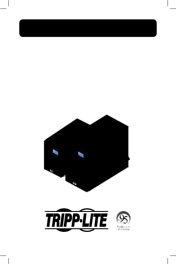
Owner’s Manual
SmartOnline®
True On-Line Single-Phase UPS Systems
with Pure Sine Wave Output
Models: SUINT1000XLCD, SUINT2000XLCD, SUINT3000XLCD
Input: 220/230/240V
Español 25 • Français 49 • Русский 73 • Deutsch 97
1111 W. 35th Street, Chicago, IL 60609 USA • www.tripplite.com/support
Copyright © 2019 Tripp Lite. All rights reserved.
1
18-09-252-93358B.INDB 1 |
1/9/2019 2:19:26 PM |

Table of Contents
1. |
Important Safety Warnings.................. |
3 |
|
|
1.1 |
UPS Location Warnings................... |
3 |
|
1.2 |
UPS Connection Warnings............... |
3 |
|
1.3 |
Equipment Connections Warnings .... |
3 |
|
1.4 |
Battery Warnings............................ |
3 |
|
1.5 |
Standard Compliance ..................... |
4 |
|
1.6 |
Storage......................................... |
4 |
2. |
Introduction ........................................ |
5 |
|
|
2.1 |
General Overview ........................... |
5 |
|
2.2 |
Exterior & Dimensions..................... |
5 |
|
2.3 |
Package Contents .......................... |
6 |
3. |
Operation Panel .................................. |
7 |
|
|
3.1 |
LED Indicators ............................... |
7 |
|
3.2 |
Multi-function Buttons .................... |
7 |
|
3.3 |
LCD Display................................... |
8 |
|
3.4 |
7-Segment Display....................... |
10 |
|
3.5 |
Flow Chart of the |
|
|
|
7-Segment Display....................... |
11 |
4. |
Rear Panel........................................ |
13 |
|
5. |
Operation Modes .............................. |
14 |
|
|
5.1 |
Standby Mode ............................. |
14 |
|
5.2 |
On-line Mode............................... |
14 |
|
5.3 |
Bypass Mode............................... |
14 |
|
5.4 |
Economy Mode............................ |
14 |
|
5.5 |
Battery Mode............................... |
14 |
|
5.6 |
Setup Mode ................................ |
15 |
|
5.7 |
External Battery Type |
|
|
|
Selection Mode............................ |
17 |
6. |
Turn-on, Cold Start & |
|
|
|
Turn-off Procedures .......................... |
18 |
|
|
6.1 |
Turn-on Procedures ...................... |
18 |
|
6.2 |
Cold Start Procedures................... |
18 |
|
6.3 |
Turn-off Procedures ...................... |
18 |
7. |
Alarm................................................ |
18 |
|
8. |
Optional Accessories ........................ |
19 |
|
|
8.1 |
Additional Power Management |
|
|
|
Features ...................................... |
19 |
9. |
Troubleshooting ................................ |
20 |
|
10. |
Maintenance..................................... |
21 |
|
|
10.1 Maintenance Safety Warnings ...... |
21 |
|
|
10.2 UPS........................................... |
22 |
|
|
10.3 Batteries .................................... |
22 |
|
|
10.4 Recycling the Used Battery........... |
22 |
|
11. |
Technical Speciications.................... |
23 |
|
12. |
Regulatory Compliance ..................... |
24 |
|
2
18-09-252-93358B.INDB 2 |
1/9/2019 2:19:26 PM |

1. Important Safety Warnings
SAVE THESE INSTRUCTIONS
This manual contains instructions and warnings that should be followed during the installation, operation and storage of all Tripp Lite UPS Systems. Failure to heed these warnings may affect your warranty.
1.1 UPS Location Warnings
Install the UPS system indoors, away from excess moisture or heat, conductive contaminants, dust or direct sunlight.
•Maintain the indoor temperature between 0° C and 40° C.
•Leave adequate space around all sides of the UPS for proper ventilation.
•Do not mount unit with its front or rear panel facing down (at any angle). Mounting in this manner will seriously inhibit the unit’s internal cooling, causing product damage not covered under warranty.
1.2 UPS Connection Warnings
•Connect the UPS directly to a properly grounded AC power outlet. Do not plug the UPS into itself; this will damage the UPS.
•Do not modify the UPS system’s plug and do not use an adapter that would eliminate the UPS system’s ground connection.
•Do not use extension cords to connect the UPS to an AC outlet.
•If the UPS receives power from a motor-powered AC generator, the generator must provide clean, iltered, computer-grade output.
•Power cables should not exceed 10 m.
1.3 Equipment Connection Warnings
• Use of this equipment in life support applications where failure of this equipment can reasonably be expected to cause the failure of the life support equipment or to signiicantly affect its safety or effectiveness is not recommended. Do not use this equipment in the presence of a lammable anesthetic mixture with air, oxygen or nitrous oxide.
• The UPS system contains its own energy source (battery). The output terminals may be live even when the UPS is not connected to an AC supply.
1.4 Battery Warnings
UPS Rating |
Built-in Batteries |
Battery Qty. |
Battery Type |
Battery Voltage |
|
1kVA |
|
2 |
9 Ah Sealed |
24Vdc |
|
2kVA |
Yes |
4 |
48Vdc |
||
Lead-Acid Battery |
|||||
3kVA |
|
6 |
72Vdc |
||
|
|
•The UPS does not require routine maintenance. Do not open the UPS for any reason. There are no user-serviceable parts inside.
•Batteries can present a risk of electrical shock and burn from high short-circuit current. Observe proper precautions. Do not dispose of the batteries in a ire. Do not open the UPS or batteries. Do not short or bridge the battery terminals with any object. Disconnect and turn off the UPS before performing battery replacement. Use tools with insulated handles. Battery replacement should be performed only by authorized service personnel using the same number and type of batteries (Sealed Lead-Acid). The batteries are recyclable. Refer to your local codes for disposal requirements or visit http://www.tripplite.com/support/recycling-program for recycling information. Tripp Lite offers a complete line of UPS System Replacement Battery Cartridges (R.B.C.).Visit Tripp Lite on the Web at http://www.tripplite.com/products/battery-inder/ to locate the speciic replacement battery for your UPS.
3
18-09-252-93358B.INDB 3 |
1/9/2019 2:19:26 PM |

1. Important Safety Warnings
•Connect only Tripp Lite battery modules to the UPS system’s external battery hardware terminals.
•Do not operate the UPS without batteries.
•Fuses should be replaced only by factory authorized personnel. Blown fuses should be replaced only with fuses of the same number and type.
•Potentially lethal voltages exist within this unit as long as the battery supply is connected. Service and repair should be done only by trained personnel. During any service work, the UPS should be turned off or put into manual bypass and fuses removed from all connected battery modules.
•Do not connect or disconnect the battery modules while the UPS is operating from the battery supply or when the unit is not in bypass mode.
1.5 Standard Compliance
•CE
•EN 62040-1
•EN 62040-2 Category C2
1.6 Storage
Prior to installation
If the UPS needs to be stored prior to installation, it should be placed in a dry area. The allowable storage temperature is between -15°C and 50°C.
After usage
Press the OFF button, make sure the UPS is shutdown, disconnect the UPS from the utility power, remove all equipment from the UPS, and store the UPS in a dry and well-ventilated area at a temperature between -15°C and 50°C. Idle batteries must be recharged fully approximately every three months if the UPS needs to be stored for an extended period of time. The charging time must not be less than 24 hours each time.
Note: After storage and before start-up of the UPS, allow the UPS to adjust to room temperature (20° to 25°C) for at least one hour to avoid moisture condensation inside the UPS.
4
18-09-252-93358B.INDB 4 |
1/9/2019 2:19:26 PM |
2. Introduction
2.1 General Overview
Tripp Lite’s SUINT-Series UPS is a VFI (voltage and frequency independent) true online double conversion UPS, providing reliable and consistent sine-wave quality power to your electronic equipment. Designed to the highest quality with modern IGBT technology, the Tripp Lite SUINTSeries of UPS systems delivers a secure, reliable and uninterrupted supply of clean power to your critical loads.
Developed with a variety of ratings and a compact footprint, the SUINT-Series delivers a high output power factor and high operating eficiency, providing more actual power to the attached load.
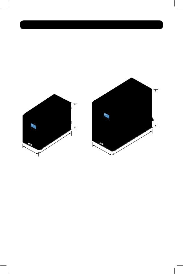
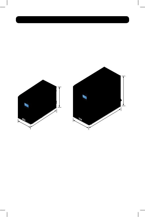
2.2 Exterior & Dimensions
225mm
325mm
145mm |
320mm |
|
Figure 2-1: SUINT1000XLCD Exterior and Dimensions
190mm |
390mm |
|
Figure 2-2: SUINT2000XLCD / SUINT3000XLCD
Exterior and Dimensions
5
18-09-252-93358B.INDB 5 |
1/9/2019 2:19:26 PM |

2.Introduction
2.3Package Contents
|
SUINT1000XLCD |
SUINT2000XLCD / |
|
|
|
SUINT3000XLCD |
|
|
|
|
|
Item |
SUINT1000XLCD |
|
SUINT2000XLCD / SUINT3000XLCD |
UPS System |
1 Pc. |
|
1 Pc. |
Owner's Manual |
1 Pc. |
|
1 Pc. |
IEC to IEC Jumpers |
2 Pc. |
|
3 Pc. |
USB Cable |
1 Pc. |
|
1 Pc. |
RS232 Cable |
1 Pc. |
|
1 Pc. |
Note:
1.Inspect the UPS system for damage after unpacking it. If there is any damage or anything is missing, immediately contact Tripp Lite Tech Support.
2.If the UPS needs to be returned, carefully repack the UPS and all of the accessories using the original packing material that came with the unit. It is recommended to retain all original packing materials.
Model-Specific Accessories (Optional)*
Model |
SUINT1000XLCD |
SUINT2000XLCD |
SUINT3000XLCD |
|
External Battery Pack (LIMIT 1) |
BP24V15RT2U or |
BP48V24-2U or |
BP72V15-2U or |
|
BP24V28-2U |
BP24V27-2US |
BP72V18-2US |
||
|
||||
External Battery Pack (NO LIMIT) |
BP24V70RT3U |
BP48V60RT3U |
BP72V28RT3U |
* Visit the speciication page for your UPS system at www.tripplite.com for detailed extended runtime data and additional accessory options.
EXTERNAL BATTERY CONFIGURATION NOTE
If external battery packs are to be used with this UPS, install them following the mounting/installation documentation included with each battery pack. External battery pack installation requires the UPS be conigured via Tripp Lite’s EXTERNAL BATTERY CONFIGURATION software, downloadable from http://www.tripplite.com/bpconig (for all external runtime conigurations)
This UPS is factory programmed with discharge curves and charging proiles for two basic external battery pack conigurations accessible using the UPS front panel LCD interface. Additional battery pack options using larger or multiple external battery packs are also supported, but require coniguration using Tripp Lite’s EXTERNAL BATTERY CONFIGURATION software and a serial port connection to the UPS. See 5.7 External Battery Type Selection Mode to determine which method applies to your external battery pack coniguration.
6
18-09-252-93358B.INDB 6 |
1/9/2019 2:19:26 PM |
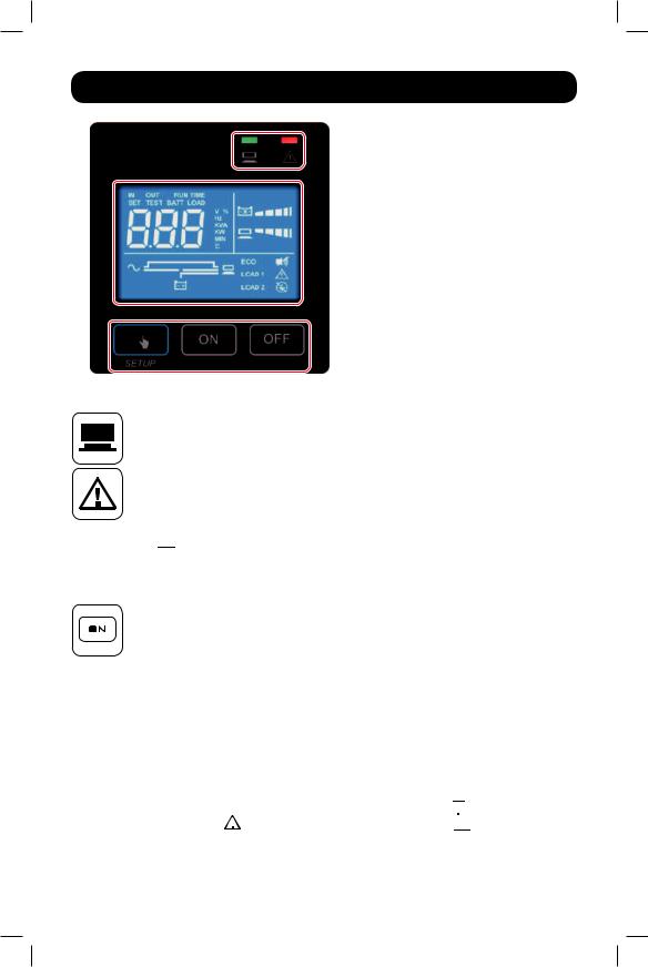
3. Operation Panel
 3.1 LED Indicators
 3.3 LCD Readout
(including 3.4 7-Segment Display)
 3.2 Multi-function Buttons
3.1 LED Indicators
GREEN LED: Indicates the output status. 1. ON (green): Output available 2. OFF: Output unavailable
RED LED:
1. ON: The UPS detects an internal fault or an environmental fault. Refer to 3.3 LCD Readout for more information.
2.Flashing: The UPS has the following warning message(s):
a. : There is no battery or battery replacement is needed.
b.


 : The UPS is overloaded.
3.2Multi-Function Buttons
ON: The button has four functions. Refer to the following for detailed information:
1. Turn-on:
•In standby mode, press and hold the button for 3 seconds. Release it after one beep. The UPS will run in on-line mode.
•Cold start: When there is no AC input, press and hold the button for 3 seconds. Release it after one beep. The UPS will start up in battery mode.
2.Battery Test: A battery test may only be executed in on-line mode.
•From manual battery test, press and hold the button for 3 seconds. Release it after one beep. The UPS will transfer to battery mode and perform a 10-second battery test.
If the test result is normal, the LCD will show ‘PAS’ and the UPS will return to online mode.
If the test result is abnormal, the LCD will show ‘bAd’, the  LED will lash, the warning icon
  and no-battery/ battery replacement icon


 will illuminate. The UPS will return to on-line mode.
7
18-09-252-93358B.INDB 7 |
1/9/2019 2:19:27 PM |

3.Operation Panel
3.Alarm Off: When the alarm is on, press the button for 0.1 second to turn the alarm off. Note that the alarm will turn on automatically when a new alarm occurs.
Note: The alarm cannot be turned on manually after it has been muted in setup.
4.Conirmation: In setup mode, press the button for 0.1 second to conirm parameter setup.
OFF: The button has two functions. Refer to the following for detailed information:
1. Turn-off:
•In on-line mode, press and hold the button for 3 seconds. Release it after one beep. The inverter will be off and the UPS will transfer to standby mode.
The UPS will keep charging the batteries in standby mode even though the button has been pressed. To fully turn off the UPS, it is advised to unplug the input power cord.
•In battery mode, press and hold the button for 3 seconds. Release it after one beep. The UPS will turn off its output.
2.Fault Clear:
When the UPS has a fault condition, press and hold the button for 3 seconds. Release it after one beep. The UPS will clear the fault condition and return to standby mode. The LCD will show the relevant error code. For error code information, refer to
3.3 LCD Readout.
SETUP: The button has two functions. Refer to the following for detailed information:
1. Scrolling down:
Press the button for 0.1 second to go to the next display.
2.Entering into the setup mode:
Press the button for 3 seconds and the UPS will enter setup mode. For more information, refer to 5.6 Setup Mode. Please note that only qualiied service personnel can perform setup actions.
Note: When the backlight of the LCD is off, press any button to wake up the display and enable each button function.
3.3 LCD
AC Icon: Indicates the input source status.
1. ON: The AC input is within the acceptable input voltage range.
2.Flashing: The AC input is out of the acceptable input voltage range but is still suficient to let the unit operate in on-line mode.
3.OFF: The AC input is out of the acceptable input voltage range and is not suficient to let the unit operate in on-line mode.
Output Icon: Indicates the output status.
1.ON: Output available.
2.OFF: Output unavailable.
Note: In setup Mode, the LED will be off, but output will still be available.
Battery Power Icon: Indicates the battery power status. 1. ON: On battery.
2. OFF: Output is not supplied by the battery power.
8
18-09-252-93358B.INDB 8 |
1/9/2019 2:19:27 PM |
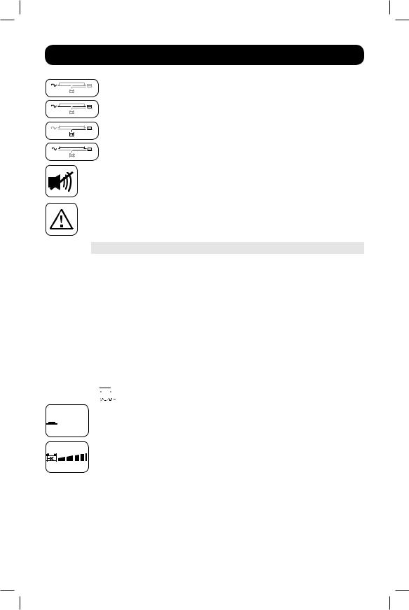
3. Operation Panel
Standby Mode Graph: Illuminates when the UPS is operating in standby mode.
On-line Mode Graph: Illuminates when the UPS is operating in on-line mode.
Battery Mode Graph: Illuminates when the UPS is operating in battery mode.
Bypass Mode Graph: Illuminates when the UPS is operating in bypass mode.
Alarm Icon: Illuminates when the alarm is disabled.
Warning Icon:
1. ON: The unit is shut down due to an internal or environmental fault. The error code will appear on the 7-segment display. Refer to the following table for each error code and refer to 3.4 7-Segment Display for relevant 7-segment display information.
Error Code |
Meaning |
E11 |
Charger Fault |
E13 |
Temperature Out of Range |
E14 |
+/- DC BUS High/Low |
E16 |
Inverter Fault |
E18 |
DC-DC Fault |
E19 |
Abnormal Output/Inverter Voltage |
E21 |
Output Short Circuit |
Sd1 |
RPO Shutdown |
Sd4 |
Battery Low Shutdown |
2.Flashing: When the icon is lashing, it will be accompanied by other icon(s) to show the corresponding warning message(s).
a.

 : There is no battery or battery replacement is needed.
b.


 : The UPS is overloaded.
Load Level Bar Graph: Indicates the load level status.


 1. ON: The bar graph illuminates according to the load level *1.
2. Flashing: The bar graph lashes when there is an overload situation. Battery Level Bar Graph: Indicates the status of battery level.
1. ON: The bar graph illuminates according to the remaining battery capacity *1. 2. Flashing: The bar graph lashes when a low-battery situation occurs.
Note: *1 means that:
<10%: no segment will illuminate. 10-29%: the irst segment will illuminate.
30-49%: the irst two segments will illuminate.
50-69%: the irst three segments will illuminate.
70-89%: the irst four segments will illuminate.
90-100%: all segments will illuminate.
9
18-09-252-93358B.INDB 9 |
1/9/2019 2:19:28 PM |
3.Operation Panel
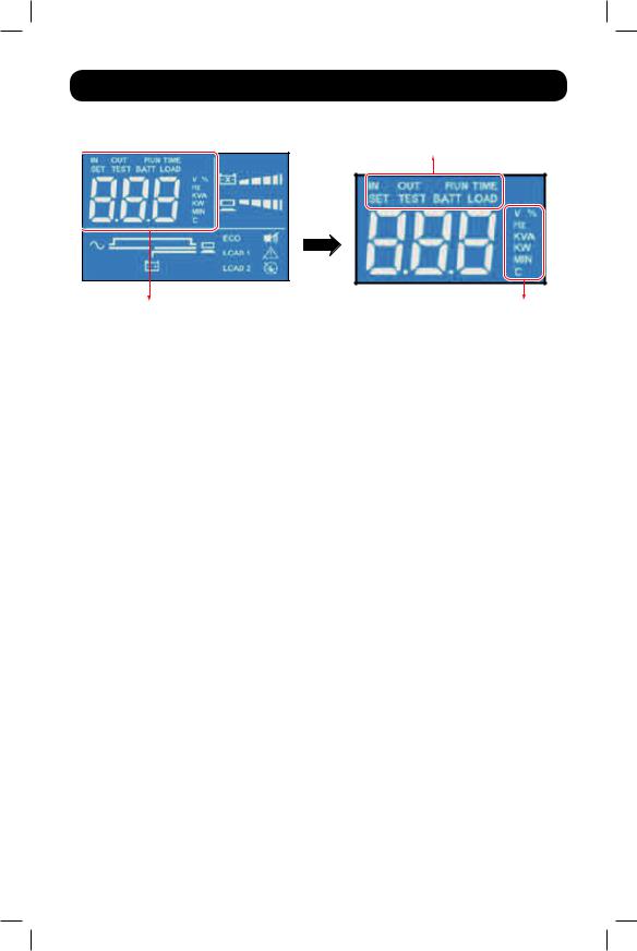
3.47-Segment Display
Row A
7-Segment Display |
Column B |
Note: Read the text shown in Row A together with that in Column B to understand the display meaning.
IN
1.IN & V: When the two illuminate together, it indicates input voltage.
2.IN & Hz: When the two illuminate together, it indicates input frequency.
OUT
1.OUT & V: When the two illuminate together, it indicates output voltage.
2.OUT & Hz: When the two illuminate together, it indicates output frequency.
RUN TIME
RUNTIME & MIN: When the two illuminate together, it indicates the estimated remaining battery backup time.
SET
When the word ‘SET’ illuminates, it indicates the UPS is in setup mode.
You can adjust the following through the LCD. For setup instructions, refer to the Setup Mode Flow Chart in Section 5.6.
1.Inverter voltage
2.Inverter frequency
3.Bypass range
4.Economy mode
5.Alarm disable
6.Overload alarm
TEST
1.When the word ‘TEST’ lashes, it means that the UPS is under self test.
2.When the words ‘TEST’ and ‘BATT’ lash together, it indicates the UPS is under battery self test.
BATT
1.BATT & %: When the two illuminate together, it indicates the remaining battery capacity.
2.BATT & V: When the two illuminate together, it indicates battery voltage.
10
18-09-252-93358B.INDB 10 |
1/9/2019 2:19:28 PM |
3. Operation Panel
LOAD
1.LOAD & %: When the two illuminate together, it indicates how much of the UPS system’s total capacity is being used.
2.LOAD & KVA: When the two illuminate together, it indicates the total load in kVA.
3.LOAD & KW: When the two illuminate together, it indicates the total load in kW.
4.LOAD & % &  : When (LOAD), unit (%) and
  icon lash together, it indicates the UPS has an overload situation.
V
Indicates voltage.
%
Indicates percentage.
Hz
Indicates frequency. kVA
Indicates kVA. kW
Indicates kW.
MIN
Indicates minute.
°C
Indicates the UPS system’s internal temperature.
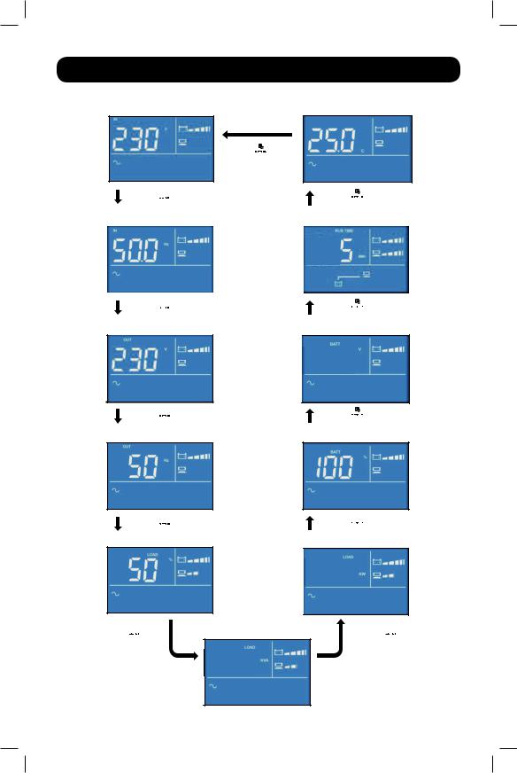
3.5 Flow Chart of the 7-Segment Display
The following low chart shows how to go through each display screen. Below, Standby Mode is used as an example. (Each of the display diagrams shown below is for reference only. Actual display depends on the UPS operation.)
After this screen appears for approximately 10 seconds, the scrolling function will be active. The scrolling button is  .
.
11
18-09-252-93358B.INDB 11 |
1/9/2019 2:19:28 PM |
3. Operation Panel
Input Voltage |
Internal Temperature |
Press the  button for 0.1 second to view the next display.
Press the  button for 0.1 second to view the next display.
Press the  button for 0.1 second to view the next display.
Input Frequency |
Estimated Runtime |
|
|
|
|
|
|
|
|
|
|
Press the  button for 0.1 second to view the next display.
Press the  button for 0.1 second to view the next display.
Output Voltage
Press the  button for 0.1 second to view the next display.
Output Frequency
Press the  button for 0.1 second to view the next display.
Load Percentage
Press the  button for 0.1 second to view the next display.
Load KVA
0.50
Battery Voltage
 24.0
24.0
Press the  button for 0.1 second to view the next display.
% Battery Charge
Press the  button for 0.1 second to view the next display.
Load KW
 0.45
0.45
Press the  button for 0.1 second to view the next display.
12
18-09-252-93358B.INDB 12 |
1/9/2019 2:19:29 PM |

4. Rear Panel
|
1 |
3 |
1 |
3 |
1 |
3 |
|
|
|
|
2 |
4 |
2 |
4 |
|
|
|
||
|
4 |
|
|
|
2 |
|
|
|
|
|
5 |
5 |
|
5 |
7 |
7 |
6 |
7 |
6 |
|
6 |
|
||
|
|
|
|
|
SUINT1000XLCD |
SUINT2000XLCD |
|
SUINT3000XLCD |
|
Number |
Item |
Function |
|
|
Install an optional communication card in this slot to
1 Accessory Slot control and monitor the UPS system’s status remotely via a network. See tripplite.com for current network card options.
2 |
Output Sockets |
Connect to the loads. |
Connects to the computer. You can monitor the UPS
3 USB Port, RS-232 Port system locally via your computer by installing optional free PowerAlert software (downloadable from
www.tripplite.com/poweralert).
4 |
Fan(s) |
Cool(s) and ventilate(s) the UPS. |
|
|
|
|
|
5 |
Input Breaker |
This is the input power’s protective device and is for safety |
|
protection. |
|||
|
|
||
6 |
AC Input Socket |
Connects the UPS to the mains. |
|
|
|
|
|
7 |
External Battery |
Extend battery backup runtime with the addition of optional |
|
Connector |
external battery. |
||
|
13
18-09-252-93358B.INDB 13 |
1/9/2019 2:19:29 PM |

5. Operation Modes
Note:
1.Refer to 3. Operation Panel for details on using the operation panel and understanding the display meaning.
2.Each of the display diagrams shown in this chapter is for reference only. Actual display depends on the UPS operation.
5.1 Standby Mode
After the UPS is connected to the AC utility, it will supply power to the UPS and the batteries will be charged. The default setting of the UPS is ‘STANDBY mode’.
5.2 On-line Mode
In on-line mode, the connected loads are supplied by the inverter, which derives its power from the utility AC power. The UPS charges the batteries and provides power protection to its connected loads.
5.3 Bypass Mode
In bypass mode, the critical loads are directly supplied by the utility power and the batteries are charged.
5.4 Economy Mode
Economy mode refers to an optional UPS coniguration for reduced power consumption and heat output. A UPS in economy mode reduces power consumption by suspending the double conversion (AC-to-DC / DC-to-AC) process whenever input power is already of high enough quality to pass through to connected equipment unchanged. The UPS will automatically switch back to on-line mode if input power quality deteriorates to ensure connected equipment receives high-quality power under all conditions.
5.5 Battery Mode
When the UPS is operating during a power outage, the batteries’ DC power is inverted to AC and continues to provide power to the attached load(s) until a graceful shutdown can be completed.
Tripp Lite’s PowerAlert software is downloadable free of charge at www.tripplite.com/poweralert to monitor remaining battery capacity before and during a power outage. An optional SNMP card may be used to monitor and control the UPS across a network. Refer to www.tripplite.com/products/power-management-software-hardware~10 for more details on Tripp Lite’s SNMP management cards.
14
18-09-252-93358B.INDB 14 |
1/9/2019 2:19:29 PM |

5. Operation Modes
5.6 Setup Mode
Press the scrolling button  for more than 3 seconds to enter the setup menu.
Note: only qualiied service personnel may perform setup actions. In setup mode, the following items can be adjusted:
1.Inverter voltage
2.Inverter frequency
3.Bypass range
4.Economy mode
5.Alarm disable
6.Overload alarm
For setup procedures, refer to the following:
1.Press the scrolling button  for more than 3 seconds to enter into the setup mode.
2.Press the scrolling button  for 0.1 second to change the parameter.
3.Press the conirmation button  for 0.1 second to conirm your parameter.
4.You can skip to the next setup item by pressing the cancel button  for 0.1 second.
5.In setup mode, press the scrolling button  for more than 3 seconds. The LCD will go to the original display.
6.In setup mode, if no button is pressed for more than 2 minutes, the LCD will exit from the setup mode and return to the original display.
This UPS supports a variety of advanced coniguration options that can be accessed via the front panel LCD screen. Coniguration and information items include Inverter Voltage, Inverter Frequency, Bypass Range, Economy Mode, Alarm Setup and Overload Alarm Setup. Some settings cannot be changed in certain operation modes. Refer to the table below for details:
Setup Item |
Standby Mode |
On-line Mode |
Bypass Mode |
Battery Mode |
Inverter Voltage |
Yes |
No |
Yes |
No |
Inverter Frequency |
Yes |
No |
Yes |
No |
Bypass Range |
Yes |
Yes |
Yes |
Yes |
Economy Mode |
Yes |
Yes |
Yes |
Yes |
Alarm Disable |
Yes |
Yes |
Yes |
Yes |
Overload Alarm |
Yes |
Yes |
Yes |
Yes |
Note: Only qualiied service personnel may perform setup actions.
15
18-09-252-93358B.INDB 15 |
1/9/2019 2:19:29 PM |
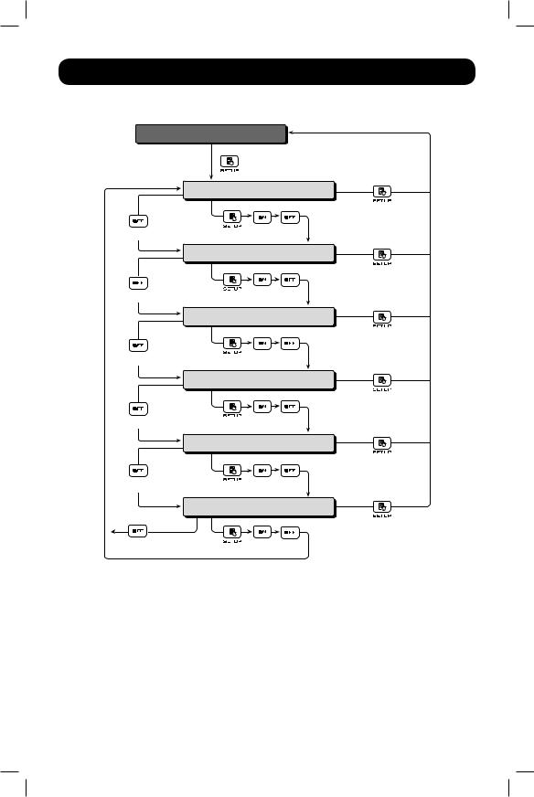
5. Operation Modes
Setup Mode Flow Chart
T>0.1S
T>0.1S
T>0.1S
T>0.1S
T>0.1S
Original Display
T>3 seconds
Inverter Voltage Setup
T>3 seconds
T=0.1S T>0.1S T>0.1S
Inverter Frequency Setup
T>3 seconds
T=0.1S T>0.1S T>0.1S
Bypass Range Setup
T>3 seconds
T=0.1S T>0.1S T>0.1S
Economy Mode Setup
T>3 seconds
T=0.1S T>0.1S T>0.1S
Alarm Setup
T>3 seconds
T=0.1S T>0.1S T>0.1S
Overload Alarm Setup
T>3 seconds
T=0.1S T>0.1S T>0.1S
Inverter Voltage Setup
OUTPUT VOLTAGE refers to the nominal output voltage of the UPS. This value is most commonly set to match the prevailing country or region-speciic nominal voltage.
Note: Certain voltage settings will cause automatic de-rating. See speciications on unit label for de-rating info.
Inverter Frequency Setup
OUTPUT FREQUENCY refers to the cycles per second (Hz) of UPS output power. To conigure your UPS to convert frequency when in Battery Mode (default 50Hz) from 50-to-60Hz or 60-to-50Hz, set the OUTPUT FREQUENCY to the desired setting. The frequency will return to the source frequency when source is applied.
16
18-09-252-93358B.INDB 16 |
1/9/2019 2:19:30 PM |

5. Operation Modes
Bypass Range Setup
BYPASS RANGE: Sets the allowable voltage deviation (in percentage %) from nominal input voltage that is acceptable for the unit to go to bypass in a fault condition. If the voltage goes outside the range, the unit will not go to bypass. If the unit is already in bypass, it will turn the output off. The factory setting of 15% of 230V is compatible with the vast majority of networking equipment.
Bypass Range Table
5% to 15% = -5%, +5% to -15%, +15% HI 1 = -20% to +15%
HI 2 = -25% to +15%
HI 3 = (120V to 226V)
Economy Mode Setup
ECONOMY MODE is a UPS setting that enables enhanced eficiency and reduced BTU output by suspending double-conversion circuits whenever input power is already of suficient quality to run connected equipment. If enabled, the UPS will run in economy mode when the voltage is within ±10% of nominal. If the voltage goes beyond the ±10% range, the UPS returns to on-line mode.
Note: Economy Mode is off by default.
Alarm Setup
The ALARM screen gives the user the ability to permanently enable or disable the UPS system’s audible alarm in case of an alarm event. The factory default of ON is ideal for most applications. Certain applications may require the alarm to be disabled, in which case the OFF option may be selected.
Overload Alarm Setup
OVERLOAD ALARM refers to the point at which the UPS will sound its overload alarm. The factory setting of 105% will provide adequate overload warnings for most applications, but alternative values from 5% to the 105% default (in 5% intervals) are available for custom conigurations.
5.7 External Battery Type Selection Mode
EXTERNAL BATTERY TYPE refers to the ability for the UPS to become aware of which external battery pack is connected to the UPS. Setting the external battery coniguration enhances the accuracy of the MINUTES RUNTIME countdown during power failure conditions. To update the runtime, you must use Tripp Lite’s EXTERNAL BATTERY CONFIGURATION TOOL software available for download at this link: http://www.tripplite.com/bpconig.
17
18-09-252-93358B.INDB 17 |
1/9/2019 2:19:30 PM |

6. Turn-on, Cold Start & Turn-off Procedures
Note: Refer to 3. Operation Panel for details on the operation panel and the display meaning.
6.1 Turn-on Procedures
After the UPS is connected to the AC utility, the AC utility supplies power to the UPS. The UPS is initially set In Standby Mode. To turn on the UPS, press and hold the  button for 3 seconds. Release it after one beep.
6.2 Cold Start Procedures
Even when there is no utility power, the UPS can be turned on. Press and hold the  button for 3 seconds. Release it after one beep and the UPS will start up and run in Battery Mode.
6.3 Turn-off Procedures
1.To turn off the UPS in On-line Mode, press and hold the  button for 3 seconds. Release it after hearing one beep. The inverter will turn off and the UPS will transfer to Standby Mode.
The UPS will keep charging the batteries when the UPS is in Standby Mode even though the  button has been pressed. To fully turn off the UPS, unplug the input power cord.
2.To turn off the UPS in Battery Mode, press and hold the  button for 3 seconds. Release it after hearing one beep. The UPS will turn off its output.
7.Alarm
Battery Mode: The audible alarm beeps once every 2 seconds. Low Battery: The audible alarm beeps once every 0.5 second.
Bad Battery/Battery Replacement*: The audible alarm beeps once every 2 seconds.
Overload:
1.Overloaded 105-125%: The audible alarm beeps once every 2 seconds.
2.Overloaded 125-150%: The audible alarm beeps once every 0.5 second.
Fault: The audible alarm beeps continuously for 5 seconds if the UPS detects an internal fault.
* After reconnecting or replacing the batteries, it may take a short time for the UPS to switch off the alarm automatically. If, after a period of time, the audible alarm still exists, the user should manually initiate a battery test (press and hold the  button for 3 seconds and release it after hearing one beep) to clear the alarm.
18
18-09-252-93358B.INDB 18 |
1/9/2019 2:19:30 PM |

8. Optional Accessories
PowerAlert® Software: Automatic shutdown software is available for use with Tripp Lite’s SUINTSeries UPS systems to allow for graceful and automatic shutdown of the connected loads in the event of an extended power failure. To download the appropriate PowerAlert software free of charge, visit www.tripplite.com/poweralert.
Several optional accessories are available for Tripp Lite’s SUINT-Series UPS systems, including communication and remote monitoring, as well as associated battery cabinets for extended runtime. Refer to www.tripplite.com for all accessories currently available.
8.1 Additional Power Management Features
Via an optional network management card: Using a Tripp Lite network management card accessory, this UPS system supports most of the same coniguration options available from the front panel LCD screen, as shown in Section 5, plus a few additional conigurations.
These additional coniguration items are available via the network management card interface:
BATTERY SAVE option enables automatic UPS power-off in battery mode when there is no need for continued operation. This option prevents unnecessary battery discharge by shutting off UPS power once the load level falls below a user-selectable percentage for ive continuous minutes. Settings are available to enable shutdown at load levels between 5% and 95% (in 5% increments). The user may determine the ideal percentage setpoint by monitoring the UPS LCD load level screen for typical power consumption in both operating and shutdown modes. For example, if the connected equipment normally consumes 40-100% UPS capacity while operational, but drops to 3% once shutdown, a BATTERY SAVE percentage setting of 5% would be ideal. Once connected equipment power consumption falls below the selected percentage for 10 continuous minutes, the UPS will turn off automatically, preventing unnecessary battery discharge. The factory default for this option is DISABLED.
BATTERY TEST refers to the ability of the UPS to perform regular self-tests of the battery system. During BATTERY TEST operation, the UPS will momentarily cycle to Battery Mode and alert users of potential UPS operational or battery-related fault conditions. The factory coniguration of MONTHLY is ideal for most applications. Options for WEEKLY and DISABLE settings are also available.
OFF MODE screen allows users to enable the UPS to provide output power when running in standby mode. The standby mode factory coniguration is NO OUTPUT.
Via RS-232 connection: This UPS supports coniguration of economy mode, audible alarms and extended runtime conigurations using PowerAlert software and a RS-232 connection to the UPS. These two parameters offer the same control options available through the front panel LCD interface. Refer to Section 5 for description and settings options.
Via USB connection: This UPS supports coniguration of the alarm using PowerAlert software and a USB connection to the UPS. Refer to Section 5 for description and settings options for Alarm Setup.
19
18-09-252-93358B.INDB 19 |
1/9/2019 2:19:30 PM |

9. Troubleshooting
If the UPS displays an error code, refer to the table below to diagnose and solve the problem:
Error codes shown on the 7-segment Display:
Error |
|
|
|
Code |
Meaning |
Possible Cause |
Solution |
|
|
|
|
E11 |
Charger Fault |
Charger is operating |
Contact Tripp Lite Tech Support. |
|
|
abnormally or not at all. |
|
|
|
|
|
E13 |
Temperature |
The UPS temperature is out |
1. Check whether the UPS’s |
|
Out of Range |
of range. |
ventilation is normal and |
|
|
|
suficient. |
|
|
|
2. Decrease the loads. |
|
|
|
3. Check whether the fan(s) run(s) |
|
|
|
normally. |
|
|
|
|
E14 |
+/- DC BUS High/ Low |
The UPS is operating |
Contact Tripp Lite Tech Support. |
|
|
abnormally. |
|
|
|
|
|
E16 |
Inverter Fault |
The UPS is operating |
Contact Tripp Lite Tech Support. |
|
|
abnormally. |
|
|
|
|
|
E18 |
DC-DC Fault |
The UPS is operating |
Contact Tripp Lite Tech Support. |
|
|
abnormally. |
|
|
|
|
|
E19 |
Abnormal Output/ |
The UPS is operating |
Contact Tripp Lite Tech Support. |
|
Inverter Voltage |
abnormally. |
|
|
|
|
|
E21 |
Output Short Circuit |
Output has a short-circuit |
1. Check whether the output has a |
|
|
issue. |
short-circuit issue. |
|
|
|
2. Contact Tripp Lite Tech Support. |
|
|
|
|
Sd1 |
RPO Shutdown |
Remote shutdown is |
There is a 5 minute delay before |
|
|
executed. |
shutdown is complete. After remote |
|
|
|
shutdown events are eliminated, |
|
|
|
follow the turn-on procedures to |
|
|
|
start the UPS. |
|
|
|
|
Sd4 |
Battery Low Shutdown |
The UPS transfers to run |
1. Check the main AC source and |
|
|
in battery mode due to AC |
the input power cord’s status. |
|
|
utility abnormality; however, |
2. Run battery test. |
|
|
the battery power is almost |
3. Contact Tripp Lite Tech Support. |
|
|
depleted. |
|
|
|
|
|
|
|
|
|
20
18-09-252-93358B.INDB 20 |
1/9/2019 2:19:30 PM |
10. Maintenance
Other problems that may occur:
Problem |
Possible Cause |
Solution |
|
|
|
Overload |
The UPS is overloaded. |
Remove some of the connected loads. |
|
|
|
Bad Battery/ |
Batteries are damaged or |
Contact Tripp Lite Tech Support. |
Battery Replacement |
battery life has expired. |
|
|
|
|
Abnormal Input |
The AC input voltage or |
1. Check whether the AC input voltage or |
(when the AC icon |
frequency is out of the |
frequency is abnormal. |
is lashing) |
acceptable range. |
2. Contact Tripp Lite Tech Support. |
|
|
|
Note: If a problem occurs, ensure mains input voltage is present. If all possible causes are eliminated but the alarm still appears, please contact Tripp Lite Tech Support. Have the following information ready when contacting Tripp Lite Tech Support:
•Unit information including model, serial number, etc.
•An exact description of the problem: the more detailed description of the problem, the better
10.1 Maintenance Safety Warnings
•The UPS is designed to supply power even when disconnected from utility power. Only authorized service personnel may access the interior of the UPS, after disconnecting the utility and DC power.
•Battery replacement should be performed only by authorized service personnel using the same number and type of batteries (sealed lead-acid).
•Do not disconnect the batteries while the UPS is in Battery mode.
•Disconnect the charging source prior to connecting or disconnecting terminals.
•Batteries can present a risk of electrical shock or burn from high short-circuit current.
•The following PRECAUTIONS should be observed:
1.Remove watches, rings or other metal objects.
2.Use tools with insulated handles.
3.Wear rubber gloves and rubber-soled footwear.
4.Do not lay tools or metal parts on top of batteries or battery cabinets.
5.Disconnect the charging source prior to connecting or disconnecting terminal.
6.Determine if the battery is inadvertently grounded. If it is, remove the source of the ground. Contact with any part of a grounded battery can result in electrical shock. The likelihood of such shock is reduced if such grounds are removed during installation and maintenance.
21
18-09-252-93358B.INDB 21 |
1/9/2019 2:19:30 PM |

10. Maintenance
10.2 UPS
Cleaning
Regularly clean the UPS, especially the vents and openings, to ensure air lows freely into the UPS to avoid overheating. If necessary, use compressed air to clean the vents and openings to prevent any object from blocking or covering these areas.
Fan
Higher temperatures shorten fan life. When the UPS is running, ensure each fan works normally and make sure air can move freely around and through the UPS.
Note: Contact Tripp Lite Tech Support for more maintenance information. Do not perform maintenance if you are not qualiied to do so.
Regular Inspection
Check the UPS every six months and inspect:
1.The UPS, LEDs and alarm function for normal operation.
2.Battery voltage; if battery voltage is too high or too low, see Troubleshooting table in Section 9.
10.3 Batteries
The SUINT-series UPS uses sealed lead-acid batteries. Typical battery life is 3-5 years; however actual battery life depends on temperature, usage and charging/discharging frequency. High temperature environments and high charging/discharging frequency will shorten the battery life. The UPS does not require maintenance by the user; however, the batteries should be checked periodically. Follow the guidelines below to ensure a normal battery lifetime.
Keep the usage temperature at 20° to 25°C.
Idle batteries must be fully recharged every three months if the UPS is stored for an extended period of time. Fully charge the batteries (internal and external) until the Battery Level Bar Graph 


 shown on the UPS system’s LCD is fully on.
Note: Battery replacement should be performed only by qualiied service personnel. If the UPS system’s internal batteries need to be replaced, please contact your Tripp Lite dealer. During battery replacement, the loads attached to the UPS will not be protected if input power fails.
10.4 Recycling the Used Battery
•Do not dispose of batteries in a ire. The batteries may explode. Proper disposal of batteries is required. The batteries are recyclable. Refer to your local codes for disposal requirements.
•Do not open or destroy the batteries. Escaping electrolytes may be toxic and can cause injury to the skin and eyes.
•Do not discard the UPS or the UPS batteries in the trash. Please recycle Tripp Lite Products. The batteries used in Tripp Lite products are sealed lead-acid batteries. These batteries are highly recyclable. Please refer to your local codes for disposal requirements. You can call
Tripp Lite for recycling info at +1.773.869.1234. You can go to the Tripp Lite Website for up-to- date information on recycling the batteries or any Tripp Lite product. Please follow this link: http://www.tripplite.com/support/recycling-program/.
•Do not discard waste electrical or electronic equipment (WEEE) in the trash. For proper disposal, contact your local recycling/reuse or hazardous waste center.
22
18-09-252-93358B.INDB 22 |
1/9/2019 2:19:30 PM |

11. Technical Specifications
Model |
|
SUINT1000XLCD |
|
SUINT2000XLCD |
|
SUINT3000XLCD |
|
|
|
|
|
|
|
|
|
Power Rating |
|
1kVA/0.9KW |
|
2kVA/1.8KW |
|
3kVA/2.7KW |
|
|
|
|
|
|
|
|
|
Waveform |
|
|
|
Pure Sine Wave |
|
||
|
|
|
|
|
|
|
|
|
|
Nominal Voltage |
|
|
220/230/240 Vac |
|
|
|
|
|
|
||||
|
|
Voltage Range |
176-280 Vac (100% load) |
||||
|
|
|
|
|
|
|
|
Input |
|
Frequency |
|
|
50/60 Hz ± 10 Hz |
|
|
|
|
|
|
|
|
|
|
|
Power Factor |
|
|
> 0.99 (full load) |
|
||
|
|
|
|
|
|||
|
|
|
|
|
|
|
|
|
|
iTHD |
|
< 5% |
|
|
|
|
|
|
|
|
|
|
|
|
|
Connection |
C14 |
|
C14 |
|
C20 |
|
|
|
|
|
|
|
|
|
|
Power Factor |
|
0.9 |
|
|
|
|
|
|
|
|
|
|
|
|
|
Voltage |
|
|
220/230/240 Vac |
|
|
|
|
|
|
|
|
|
|
|
|
Voltage Regulation |
|
|
± 2% (linear load) |
|
|
|
|
|
|
|
|
||
|
|
Frequency |
|
50/60 Hz ± 0.05 Hz |
|
||
|
|
|
|
|
|
|
|
Output |
|
vTHD |
|
|
< 3% (linear load) |
|
|
|
|
|
|
|
|
|
|
|
|
Overload Capability |
< 105%: continuous; 105-125%: 1 minute; |
||||
|
|
126-150%: 30 seconds |
|||||
|
|
|
|||||
|
|
|
|
|
|
|
|
|
|
Crest Factor |
|
3:1 |
|
|
|
|
|
|
|
|
|
|
|
|
|
Connections |
IEC C13 (x4) |
|
IEC C13 (x7) |
|
IEC C13 (X6), |
|
|
|
|
C19 (x1) |
|||
|
|
|
|
|
|
|
|
|
|
|
|
|
|
|
|
Eficiency |
|
Online Mode |
91% |
|
93% |
||
(at Full Load) |
|
Economy Mode |
|
96% |
|
|
|
|
|
|
|
|
|
|
|
|
|
Battery Voltage |
24 Vdc |
|
48 Vdc |
|
72 Vdc |
|
|
|
|
|
|
|
|
|
|
Battery Quantity |
2 |
|
4 |
|
6 |
Battery |
|
|
|
|
|
|
|
|
Backup Runtime |
50% 13 min. |
|
50% 11 min. |
|
50% 10 min. |
|
|
|
100% 5 min. |
|
100% 3 min. |
|
100% 3 min. |
|
|
|
|
|
|
|||
|
|
|
|
|
|
|
|
|
|
Recharge Time |
|
|
6 hours to 90% |
|
|
|
|
|
|
|
|
||
Audible Noise |
|
< 49 dBA |
|
< 52 dBA |
|||
|
|
|
|
||||
Display |
|
LED Indicators & LCD Readout |
|||||
|
|
||||||
Communication Interfaces |
Accessory Slot, USB Port, RS-232 Port |
||||||
|
|
|
|
|
|
|
|
|
|
Dimensions (W×D×H) |
145 x 320 x |
|
190 x 390 x |
|
190 x 390 x |
Physical |
|
225 mm |
|
325 mm |
|
325 mm |
|
|
|
|
|
||||
|
|
Weight |
9.5 kg |
|
19.4 kg |
|
25.8 kg |
|
|
|
|
|
|
|
|
Environment |
|
Operating Temperature |
|
|
0-40°C |
|
|
|
|
|
|
|
|
|
|
|
Relative Humidity |
5-95% (non-condensing) |
|||||
|
|
||||||
|
|
|
|
|
|
|
|
23
18-09-252-93358B.INDB 23 |
1/9/2019 2:19:30 PM |

12. Regulatory Compliance
Regulatory Compliance Identiication Numbers
For the purpose of regulatory compliance certiications and identiication, your Tripp Lite product has been assigned a unique series number. The series number can be found on the product nameplate label, along with all required approval markings and information. When requesting compliance information for this product, always refer to the series number. The series number should not be confused with the marketing name or model number of the product.
WEEE Compliance Information for Tripp Lite Customers and Recyclers (European Union)
Under the Waste Electrical and Electronic Equipment (WEEE) Directive and implementing regulations, when customers buy new electrical and electronic equipment from Tripp Lite they are entitled to:
•Send old equipment for recycling on a one-for-one, like-for-like basis (this varies depending on the country)
•Send the new equipment back for recycling when this ultimately becomes waste
Tripp Lite has a policy of continuous improvement. Speciications are subject to change without notice.
1111 W. 35th Street, Chicago, IL 60609 USA • www.tripplite.com/support
24
18-09-252-93358B.INDB 24 |
1/9/2019 2:19:30 PM |
Manual del Propietario
SmartOnline®
Sistemas UPS Monofásicos 100% en Línea con Salida de Onda Sinusoidal Pura
Modelos: SUINT1000XLCD, SUINT2000XLCD,
SUINT3000XLCD
Entrada: 220/230/240V
English 1 • Français 49 • Русский 73 • Deutsch 97
1111 W. 35th Street, Chicago, IL 60609 EE. UU. • www.tripplite.com/support
Copyright © 2019 Tripp Lite. Todos los derechos reservados.
25
18-09-252-93358B.INDB 25 |
1/9/2019 2:19:30 PM |

Índice
1. |
Advertencias Importantes |
|
|
|
de Seguridad .................................... |
27 |
|
|
1.1 |
Advertencias para la Ubicación |
|
|
|
del UPS ...................................... |
27 |
|
1.2 |
Advertencias sobre la Conexión |
|
|
|
del UPS ...................................... |
27 |
|
1.3 |
Advertencias para Conectar |
|
|
|
el Equipo..................................... |
27 |
|
1.4 |
Advertencias de la Batería............. |
27 |
|
1.5 |
Compatibilidad con Estándar ......... |
28 |
|
1.6 |
Almacenamiento .......................... |
28 |
2. |
Introducción ..................................... |
29 |
|
|
2.1 |
Descripción General ..................... |
29 |
|
2.2 |
Exterior y Dimensiones.................. |
29 |
|
2.3 |
Contenido del Empaque................ |
30 |
3. |
Panel de Operación........................... |
31 |
|
|
3.1 |
Indicadores LED........................... |
31 |
|
3.2 |
Botones Multi-función .................. |
31 |
|
3.3 |
Pantalla LCD................................ |
32 |
|
3.4 |
Pantalla de 7 Segmentos.............. |
34 |
|
3.5 |
Diagrama de Flujo de la |
|
|
|
Pantalla de 7 Segmentos.............. |
35 |
4. |
Panel Posterior ................................. |
37 |
|
5. |
Modos de Operación ......................... |
38 |
|
|
5.1 |
Modo en Espera........................... |
38 |
|
5.2 |
Modo En Línea ............................ |
38 |
|
5.3 |
Modo en Derivación ..................... |
38 |
|
5.4 |
Modo Económico ......................... |
38 |
|
5.5 |
Modo En Respaldo por Batería ...... |
38 |
|
5.6 |
Modo en Coniguración................. |
39 |
|
5.7 |
Modo de Selección |
|
|
|
de Tipo de Batería Externa ............ |
41 |
6. |
Procedimientos de Encendido, |
|
|
|
Arranque en Frío y Apagado .............. |
42 |
|
|
6.1 |
Procedimientos de Encendido........ |
42 |
|
6.2 |
Procedimientos de Arranque |
|
|
|
en Frío ........................................ |
42 |
|
6.3 |
Procedimientos de Apagado .......... |
42 |
7. |
Alarma.............................................. |
42 |
|
8. |
Accesorios Opcionales ...................... |
43 |
|
|
8.1 |
Características Adicionales de |
|
|
|
Administración de Energía............. |
43 |
9. |
Solución de Problemas ..................... |
44 |
|
10. |
Mantenimiento ................................. |
45 |
|
|
10.1 Advertencias de Seguridad |
|
|
|
|
para Mantenimiento ..................... |
45 |
|
10.2 UPS............................................ |
46 |
|
|
10.3 Baterías ...................................... |
46 |
|
|
10.4 Reciclado de la Batería Usada ....... |
46 |
|
11. |
Especiicaciones Técnicas................. |
47 |
|
12. |
Cumplimiento de las Normas ............ |
48 |
|
26
18-09-252-93358B.INDB 26 |
1/9/2019 2:19:30 PM |
1. Advertencias Importantes de Seguridad
CONSERVE ESTAS INSTRUCCIONES
Este manual contiene instrucciones y advertencias que deben seguirse durante la instalación, operación y almacenamiento de todos los Sistemas UPS de Tripp Lite. La omisión en la observancia de estas advertencias puede afectar su garantía.
1.1 Advertencias para la Ubicación del UPS
Instale su UPS en interiores, alejado de humedad o calor excesivos, contaminantes conductores, polvo o luz solar directa.
•Mantenga la temperatura interior entre 0 °C y 40 °C.
•Deje espacio adecuado alrededor del UPS para una ventilación apropiada.
•No instale la unidad con su panel frontal o posterior viendo hacia abajo (en cualquier ángulo). Instalarlo de esta manera inhibirá seriamente el enfriamiento interno de la unidad, causando daño al producto no cubierto por la garantía.
1.2 Advertencias para la Conexión del UPS
•Conecte el UPS directamente a un tomacorriente de CA conectado correctamente a tierra. No enchufe el UPS en sí mismo; esto dañará al UPS.
•No modiique la clavija del sistema UPS ni use un adaptador que pueda eliminar la conexión a tierra del UPS.
•No use cables de extensión para conectar el UPS a un tomacorriente de CA.
•Si el UPS recibe alimentación de un generador de CA activado por motor, debe probarse que el generador proporciona una salida de grado computadora, limpia y iltrada.
•Los cables de alimentación no deben exceder de 10 m.
1.3 Advertencias para la Conexión del Equipo
• No se recomienda el uso de este equipo en aplicaciones de soporte de vida en donde la falla de este equipo pueda razonablemente causar la falla del equipo de soporte de vida o afectar signiicativamente su seguridad o efectividad. No use este equipo en presencia de una mezcla inlamable de anestésicos con aire, oxígeno u óxido nitroso.
• El sistema UPS contiene su propia fuente de energía (batería). Las terminales de salida pueden estar energizadas, aún cuando el UPS no esté conectado a una alimentación de CA.
1.4 Advertencias de la Batería
Especiicación |
Baterías |
Cant. de |
Tipo de Batería |
Voltaje de la |
|
del UPS |
Incorporadas |
Baterías |
Batería |
||
|
|||||
1kVA |
|
2 |
Batería de Plomo |
24VCD |
|
2kVA |
Sí |
4 |
48VCD |
||
Sellada de 9 Ah |
|||||
3kVA |
|
6 |
72VCD |
||
|
|
•El UPS no requiere mantenimiento de rutina. No abra el UPS por motivo alguno. No tiene partes a las que el usuario pueda dar servicio.
•Las baterías pueden presentar un riesgo de choque eléctrico y quemaduras por la alta corriente de corto circuito. Observe las precauciones apropiadas. No deseche las baterías en el fuego. No abra el UPS o las baterías. No ponga en corto o puentee las terminales de la batería con ningún objeto. Desconecte y apague el UPS antes de reemplazar la batería. Use herramientas con mangos aislados. El reemplazo de la batería debe realizarlo solo el personal de servicio autorizado usando el mismo número y tipo de baterías (Plomo-Ácido Selladas). Las baterías son reciclables. Para información sobre el reciclado, consulte sus códigos locales para los requisitos
de desecho o visite http://www.tripplite.com/support/recycling-program. Tripp Lite ofrece una línea completa de Cartuchos de Batería de Repuesto (R.B.C.) para Sistemas UPS. Para localizar la batería de repuesto especíica para su UPS, visite Tripp Lite en el sitio http://www.tripplite.com/products/battery-inder/.
27
18-09-252-93358B.INDB 27 |
1/9/2019 2:19:30 PM |

1. Advertencias Importantes de Seguridad
•Conecte solamente módulos de baterías de Tripp Lite a las terminales de la batería externa del sistema UPS.
•No opere su UPS sin baterías.
•Los fusibles deben ser reemplazados solamente por personal autorizado por la fábrica. Los fusibles quemados deben ser reemplazados solamente con fusibles del mismo número y tipo.
•Dentro de esta unidad existen voltajes potencialmente peligrosos en tanto la alimentación por batería esté activa. El servicio y reparación debe ser realizado solo por personal capacitado. Durante cualquier trabajo de servicio, el UPS debe ser apagado o colocado en derivación manual y los fusibles retirados de todos los módulos de baterías conectados.
•No conecte ni desconecte los módulos de baterías mientras el UPS esté funcionando con suministro de la batería o cuando la unidad no se encuentre en modo de derivación.
1.5 Cumple con el Estándar
•CE
•EN 62040-1
•EN 62040-2 Categoría C2
1.6 Almacenamiento
Antes de la instalación
Si necesita almacenar el UPS antes de la instalación, debe colocarse en un área seca. La temperatura permisible de almacenamiento está entre -15 °C y 50 °C.
Después del uso
Oprima el botón “OFF” [Apagado], asegure que el UPS esté apagado, desconecte el UPS de la energía de la red pública, retire todo el equipo del UPS y guarde el UPS en un área seca y bien ventilada a una temperatura entre -15 °C y 50 °C. Si el UPS necesite almacenarse por un período prolongado de tiempo, las baterías en reposo deben recargarse completamente cada tres meses. El tiempo de carga no debe ser menor a 24 horas cada vez.
Nota: Después de almacenar y antes de arrancar el UPS, permita que se ajuste a la temperatura del cuarto (20 °C a 25 °C) por al menos una hora para evitar condensación de humedad dentro del UPS.
28
18-09-252-93358B.INDB 28 |
1/9/2019 2:19:30 PM |
2. Introducción
2.1 Descripción General
El UPS de la Serie SUINT de Tripp Lite es un UPS de doble conversión 100% en línea VFI (independiente del voltage y la frecuencia), que suministra energía con calidad de onda sinusoidal coniable y consistente para sus equipos electrónicos. Diseñados para la más alta calidad
con moderna tecnología IGBT, los sistemas UPS de la serie SUINT de Tripp Lite entregan una alimentación segura, coniable y sin interrupción de energía limpia para sus cargas críticas.
Desarrollados con una variedad de especiicaciones y un tamaño de base compacto, la Serie SUINT entrega un alto factor de potencia de salida y alta eiciencia de operación, proporcionando más energía real a la carga conectada.
2.2 Exterior y Dimensiones
225mm
325mm
145mm |
320mm |
|
Figura 2-1: Exterior y Dimensiones del SUINT1000XLCD
190mm |
390mm |
|
Figura 2-2: Exterior y Dimensiones del SUINT2000XLCD / SUINT3000XLCD
29
18-09-252-93358B.INDB 29 |
1/9/2019 2:19:31 PM |
2.Introducción
2.3Contenido del Empaque
|
SUINT1000XLCD |
SUINT2000XLCD / |
|
|
|
SUINT3000XLCD |
|
|
|
|
|
Descripción |
SUINT1000XLCD |
|
SUINT2000XLCD / SUINT3000XLCD |
Sistema UPS |
1 Pza. |
|
1 Pza. |
Manual del Propietario |
1 Pza. |
|
1 Pza. |
Puentes de IEC a IEC |
2 Pzas. |
|
3 Pzas. |
Cable USB |
1 Pza. |
|
1 Pza. |
Cable RS232 |
1 Pza. |
|
1 Pza. |
Nota:
1.Inspeccione el sistema UPS para detectar daño después de desempacarlo. Si existe cualquier daño o falta algo, póngase en contacto de inmediato con Soporte Técnico de Tripp Lite.
2.Si el UPS necesita ser devuelto, reempaque cuidadosamente el UPS y todos los accesorios usando el material original de empaque que vino con la unidad. Es recomendable conservar todo el material del empaque original.
Accesorios Específicos del Modelo (Opcionales)*
Modelo |
SUINT1000XLCD |
SUINT2000XLCD |
SUINT3000XLCD |
|
Módulo de Baterías Externas |
BP24V15RT2U o |
BP48V24-2U o |
BP72V15-2U o |
|
(LÍMITE 1) |
BP24V28-2U |
BP24V27-2US |
BP72V18-2US |
|
Módulo de Baterías Externas |
BP24V70RT3U |
BP48V60RT3U |
BP72V28RT3U |
|
(SIN LÍMITE) |
||||
|
|
|
* Para información detallada de autonomía extendida y opciones de accesorios adicionales, visite la página de especiicación para su Sistema UPS en www.tripplite.com.
NOTA SOBRE LA CONFIGURACIÓN DE LA BATERÍA EXTERNA
Si se usarán módulos de baterías externas con este UPS, instálelos siguiendo la documentación para la instalación, incluida con cada módulo de baterías. La instalación del módulo de baterías externas requiere que el UPS sea conigurado mediante el software de CONFIGURACIÓN DE BATERÍA EXTERNA de Tripp Lite, descargable de http://www.tripplite.com/bpconig (para todas las coniguraciones de autonomía externa)
Este UPS esté programado de fábrica con curvas de descarga y periles de carga para dos coniguraciones básicas de módulos de baterías externos accesibles mediante la interfaz LCD del panel frontal del UPS. Las opciones
de módulos de baterías externas adicionales que usan módulos de baterías externas más grandes o múltiples también son soportadas, pero requieren de coniguración usando el software para CONFIGURACIÓN DE BATERÍAS EXTERNAS de Tripp Lite y una conexión de puerto serial al UPS. Para determinar qué método aplica para la coniguración de su módulo de batería externa, vea 5.7 Modo de Selección de Tipo de Batería Externa.
30
18-09-252-93358B.INDB 30 |
1/9/2019 2:19:31 PM |
 Loading...