


Owner’s Manual
SmartPro®
Intelligent, Line-Interactive UPS System
• 220/230/240V Sine Wave Input/Output • Extended Runtime Capability
Model: SMX2200XLRT2U
Not suitable for mobile applications
Important Safety Instructions
Mounting
Quick Installation
Optional Installation |
6 |
|
|
Basic Operation |
|
|
|
|
|
Storage and Service |
|
|
|
|
|
Battery Replacement |
12 |
|
|
|
|
Español |
13 |
|
|
|
|
Français |
25 |
|
|
|
|
Deutsch |
37 |
|
|
|
|
PyccŞèé |
49 |
|
|
1111 W. 35th Street Chicago, IL 60609 USA Customer Support: (773) 869-1234 • www.tripplite.com
Copyright ©2006 Tripp Lite. All rights reserved. SmartPro® is a trademark of Tripp Lite

Important Safety Instructions
SAVE THESE INSTRUCTIONS
This manual contains important instructions that should be followed during the installation, operation and storage of all Tripp Lite UPS Systems. Failure to heed these warnings will void your warranty.
UPS Location Warnings
•Use caution when lifting UPS. Because of the considerable weight of all Rackmount UPS systems, at least two people should assist in lifting and installing them.
•Install your UPS indoors, away from excess moisture or heat, dust or direct sunlight.
•For best performance, the ambient temperature near your UPS should be between 0° C and 40° C (between 32° F and 104° F).
•Leave adequate space around all sides of the UPS for proper ventilation. Do not obstruct its vents or fan openings.
UPS Connection Warnings
•The UPS contains its own energy source (battery). The output terminals may be live even when the UPS is not connected to an AC supply.
•Connect your UPS to a properly grounded AC power outlet. Do not modify the UPS’s plug in a way that would eliminate the UPS’s connection to ground. Do not use adapters that eliminate the UPS’s connection to ground.
•Do not plug your UPS into itself; this will damage the UPS and void your warranty.
•If you are connecting your UPS to a motor-powered AC generator, the generator must provide filtered, frequency-regulated computer-grade output. Connecting your UPS to a generator will void its Ultimate Lifetime Insurance.
Equipment Connection Warnings
•Do not use Tripp Lite UPS Systems for life support applications in which a malfunction or failure of a Tripp Lite UPS System could cause failure or significantly alter the performance of a life-support device.
•Do not connect surge suppressors or extension cords to the output of your UPS. This might overload the UPS and will void the surge suppressor and UPS warranties.
Battery Warnings
•Batteries can present a risk of electrical shock and burn from high short-circuit current. Observe proper precautions. Do not dispose of the batteries in a fire. Do not open the UPS or batteries. Do not short or bridge the battery terminals with any object. Unplug and turn off the UPS before performing battery replacement. Use tools with insulated handles. There are no user-serviceable parts inside the UPS. Battery replacement should be performed only by authorized service personnel using the same number and type of batteries (sealed Lead-Acid). The batteries are recyclable. Refer to your local codes for disposal requirements. Tripp Lite offers a complete line of UPS System Replacement Battery Cartridges (R.B.C.). Visit Tripp Lite on the Web at www.tripplite.com to locate the specific replacement battery for your UPS.
•During hot-swap battery replacement, the UPS will not provide backup power in the event of a blackout or other power interruptions.
•Do not operate UPS without batteries.
•When adding external battery packs to select models with external battery pack connectors, connect only Tripp Lite-recommended battery packs of the correct voltage and type. Do not connect or disconnect battery packs when the UPS is operating on battery power.
2
Mounting (Rack)
Mount your equipment in either a 4-post or 2-post rack or rack enclosure. The user must determine the fitness of hardware and procedures before mounting. If hardware and procedures are not suitable for your application, contact the manufacturer of your rack or rack enclosure. The procedures described in this manual are for common rack and rack enclosure types and may not be appropriate for all applications.
4-Post Mounting
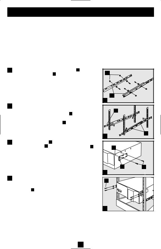
All UPS models include hardware required to mount in a 4-post rack. Select models include an adjustable rackmount shelf kit to provide additional support. If your UPS model does not include an adjustable rackmount shelf kit, skip steps 1 and 2.
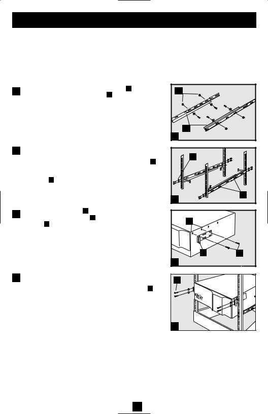
1Connect the two segments of each shelf A using the included screws and nuts B . Leave the screws slightly loose so that the shelves can be adjusted in the next step.
2Adjust each shelf to fit your rack, then mount them in the lowest available space of your rack with the screws, nuts and washers provided C . Note that the support ledges should face inward. Tighten the screws that connect the shelf segments B .
3Attach mounting ears D to the front mounting holes of your equipment E using the screws provided F . The ears should face forward.
4Using an assistant if necessary, lift your equipment and slide it onto the mounting shelves. Attach your equipment to the rack by using the appropriate hardware G through its mounting ears and into the rack rails.
B |
A |
1 |
C |
B
2
E
D |
F |
3 |
|
G |
|
4 |
|
2-Post (Telecom) Mounting
Two-post mounting will require a Tripp Lite 2-Post Rackmount Installation Kit (Model 2POSTRMKITWM, sold separately). For detailed installation procedures, see the 2POSTRMKITWM Owner's Manual.
3
Mounting (Tower)
Mount all UPS models in an upright, tower position using included hardware. The user must determine the fitness of hardware and procedures before mounting.
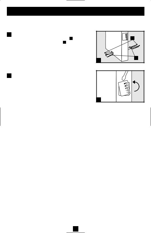
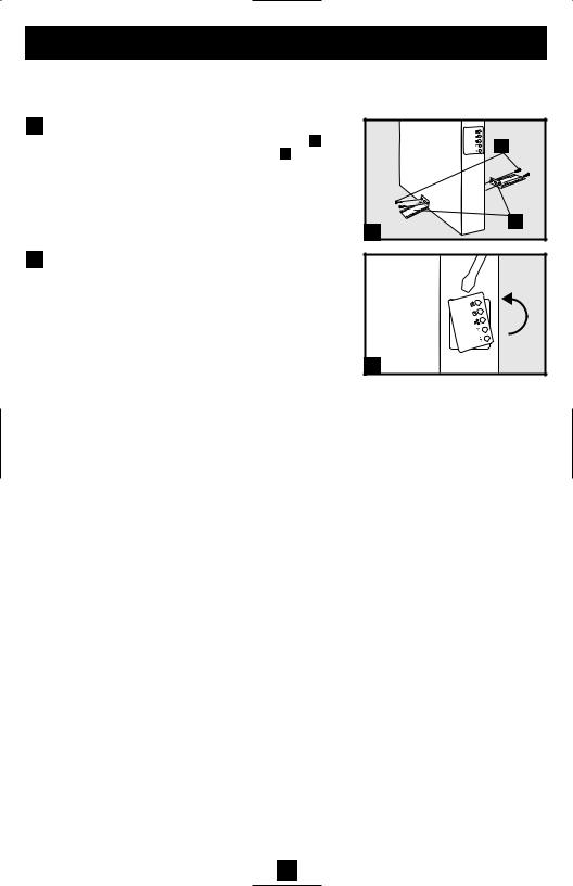
1 Stand your UPS on its side with the LED/Control panel |
B |
|
at the top. Attach one rack mounting ear A to each side |
||
of the UPS using included screws B . Attach the rack |
|
|
mounting |
ears to the floor with user-supplied |
|
hardware. |
|
|
A
1
2 Rotate the LED/Control panel to view it easier while the UPS is tower mounted. Insert a small screwdriver, or other tool, in the slots on either side of the panel. Pop the panel out; rotate it; and pop the panel back in place.
2
4
|
Quick Installation |
|
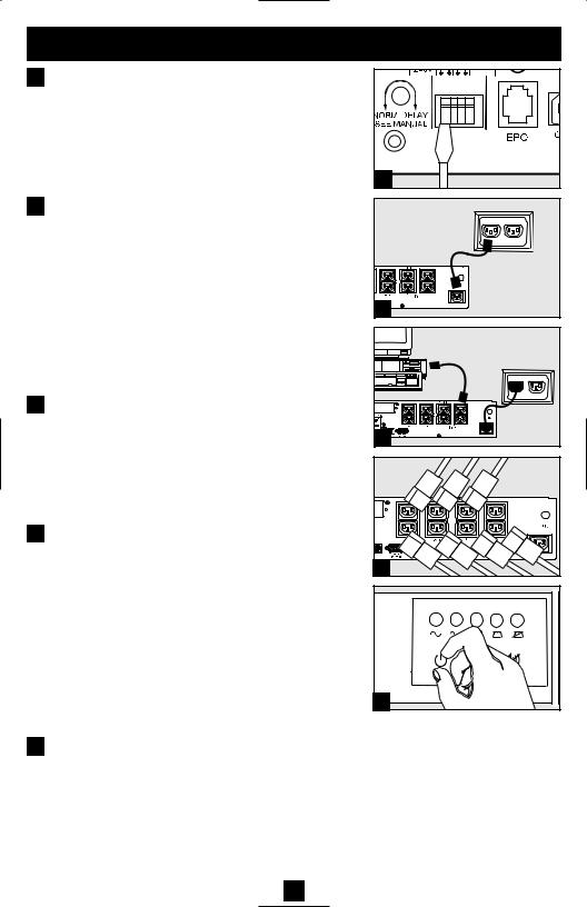
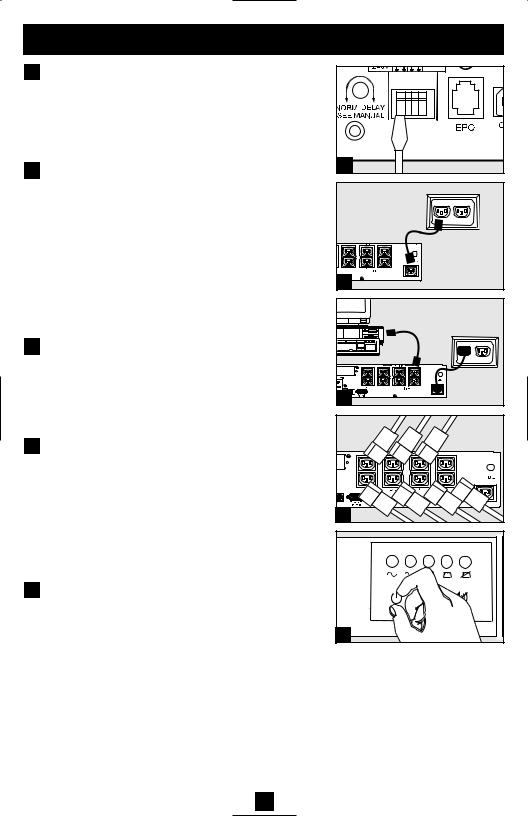
1 With the UPS disconnected from |
BATTERIES |
|
|
utility power, use a small tool to |
|
|
set the Voltage Dip Switches to |
|
|
match your input voltage. (All |
|
|
models are preset to the 230V |
|
|
setting.) |
1 |
2 Insert a user-supplied power cord |
|
|
|
(with country-specific plug) into |
|
|
the UPS System's IEC-320-C20 |
|
|
AC input receptacle. Plug the |
|
|
cord into an AC wall outlet.* |
|
|
NOTE! after you plug the UPS into a live AC outlet, |
2 |
|
the UPS (in “Standby” mode) will automatically |
|
|
|
|
|
charge its batteries,** but will not supply power to |
|
|
its outlets until it is turned ON (see Step 3 below). |
|
|
* See Specifications for circuit amperage requirements. |
|
|
** The BATTERY CHARGE LED will be the only LED illuminated. |
|
3 |
Find one of the power cords that |
|
|
came with the UPS. Insert the |
3 |
|
cord’s female plug into |
|
|
computer’s AC input. Insert the |
|
|
cord’s male plug into any UPS |
|
|
female output receptacle. |
|
4 |
Plug your equipment into the UPS.* |
|
Plug your equipment into the UPS. Repeat Step 3 above using the additional power cord(s) that came with the UPS.
Note: Additional interconnection cords (C13 to C14) are available from Tripp Lite. Call 773-869- 1234 (Part # P004-006).
* Your UPS is designed to support computer equipment only. You will overload the UPS if the total VA ratings for all the equipment you connect exceeds UPS output capacity. To find your equipment’s VA ratings, look on their nameplates. If the equipment is listed in amps, multiply the number of amps by 240 to determine VA. (Example: 1 amp × 240 = 240 VA). If you are unsure if you have overloaded your UPS's outlets, see “OUTPUT LOAD LEVEL” LED description.
4 |
5 |
5 Turn the UPS ON.
Press and hold the “ON/OFF/STANDBY” button for one second. The alarm will beep once briefly after one second has passed. Release the button.
5

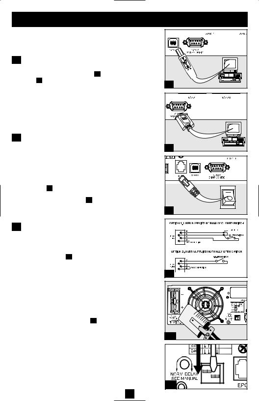
Optional Installation
These connections are optional. Your UPS will function properly without these connections.
1 USB and RS-232 Serial
Communications
Use the included USB cable (see 1a ) and/or DB9 serial
cable (see 1b ) to connect the communication port on your computer to the communication port of your UPS. Install on your computer the Tripp Lite PowerAlert Software appropriate to your computer’s operating system.
2 EPO Port Connection
This optional feature is only for those applications which require connection to a facility’s Emergency Power Off (EPO) circuit. When the UPS is connected to this circuit, it enables emergency shutdown of the UPS’s inverter.
Using the cable provided, connect the EPO port of
your UPS (see 2a ) to a user-supplied normally closed or normally open switch according to the circuit diagram
(see 2b ). The EPO port is not a phone line surge suppressor; do not connect a phone line to this port.
3 External Battery Connection
Your UPS comes with a robust internal battery system; external batteries are needed only to extend runtime. Adding external batteries will increase recharge time as well as runtime.
The illustration (see 3a ) shows the location of your UPS’s External Battery Connector, where you will insert the battery pack cable. Complete installation instructions for your battery pack appear in the battery pack owner’s manual. Make sure that cables are fully inserted into their connectors. Small sparks may result during battery connection; this is normal.
Do not connect or disconnect battery packs when the UPS is running on battery power.
If you connect any external batteries, set the Battery Charge Level Switches (see 3b ) to the down position. This will increase your UPS’s charger output so that the additional batteries charge faster.
Caution! DO NOT set the Battery Charge Level Switches to the down position without an external battery connected. There is a risk of damaging the UPS’s internal battery system.
1a |
1b |
2a |
4-5 |
2b |
3a |
EXTERNAL |
BATTERIES |
3b |
6

Basic Operation
Buttons (Front Panel)
“ON/OFF/STANDBY” Button
•To turn the UPS ON: with the UPS plugged into a live AC wall outlet*, press and hold the “ON/OFF/STANDBY” button for one second.** Release the button. If utility power is absent, you can “cold-start” the UPS (i.e.: turn it ON and supply power for a limited time from its batteries***) by pressing and holding the “ON/OFF/STANDBY” button for one second.**
•To turn the UPS OFF: with the UPS ON and receiving utility power, press and hold the “ON/OFF/STANDBY” button for one second.** Then unplug the UPS from the wall outlet. The UPS will be completely OFF.
* After you plug the UPS into a live AC outlet, the UPS (in ”Standby” mode) will automatically charge its batteries, but will not supply power to its outlets until it is turned ON. ** The alarm will beep once briefly after the indicated interval has passed. *** If fully charged.
“MUTE/TEST” Button
To Silence (or “Mute”) UPS Alarms: briefly press and release the MUTE/TEST button.*
To Run a Self-Test: with your UPS plugged in and turned ON, press and hold the MUTE/TEST button. Continue holding the button until the alarm beeps several times and the UPS performs a self test. See “Results of a Self-Test” below. Note: you can leave connected equipment on during a self-test. Your UPS, however, will not perform a self-test if the UPS is not turned on (see “ON/OFF/STANDBY” Button description).
CAUTION! Do not unplug your UPS to test its batteries. This will remove safe electrical grounding and may introduce a damaging surge into your network connections.
Results of a Self-Test: The test will last approximately 10 seconds as the UPS switches to battery to test its load capacity and battery charge.
•If the “OUTPUT LOAD LEVEL” LED remains lit red and the alarm continues to sound after the test, the UPS’s outlets are overloaded. To clear the overload, unplug some of your equipment and run the self-test repeatedly until the “OUTPUT LOAD LEVEL” LED is no longer lit red and the alarm is no longer sounding.
CAUTION! Any overload that is not corrected by the user immediately following a self-test may cause the UPS to shut down and cease supplying output power in the event of a blackout or brownout.
•If the “BATTERY WARNING” LED remains lit and the alarm continues to sound after the test, the UPS batteries need to be recharged or replaced. Allow the UPS to recharge continuously for 12 hours, and repeat the self-test. If the LED remains lit, contact Tripp Lite for service. If your UPS requires battery replacement, visit www.tripplite.com to locate the specific Tripp Lite replacement battery for your UPS.
7
Basic Operation continued
Indicator Lights (Front Panel)
All Indicator Light descriptions apply when the UPS is plugged into a wall outlet and turned ON.
“POWER” LED: this green LED lights continuously when the UPS is ON and supplying connected equipment with AC power from a utility source. The LED flashes and an alarm sounds (4 short beeps followed by a pause) to indicate the UPS is operating from its internal batteries during a blackout or severe brownout. If the blackout or severe brownout is prolonged, you should save files and shut down your equipment since internal battery power will eventually be depleted. See “BATTERY CHARGE” LED description below.
“VOLTAGE CORRECTION” LED: this green LED lights continuously whenever the UPS is automatically correcting high or low AC voltage on the utility line without the assistance of battery power. The UPS will also emit a slight clicking noise. These are normal, automatic operations of the UPS, no action is required on your part.
“OUTPUT LOAD LEVEL” LED: this multicolored LED indicates the approximate electrical load of equipment connected to the UPS's AC outlets. It will turn from green (light load) to yellow (medium load) to red (overload). If the LED is red (either illuminated continuously or flashing), clear the overload immediately by unplugging some of your equipment from the outlets until the LED changes from red to yellow (or green). CAUTION! Any overload that is not corrected by the user immediately may cause the UPS to shut down and cease supplying output power in the event of a blackout or brownout.
“BATTERY CHARGE” LED: when the UPS is operating from utility power, this LED indicates the approximate charge state of the UPS's internal batteries: red indicates the batteries are beginning to charge; yellow indicates the batteries are roughly midway through charging; and green indicates the batteries are fully charged. When the UPS is operating from battery power during a blackout or severe brownout, this LED indicates the approximate amount of energy (ultimately affecting runtime) which the UPS’s batteries will provide: red indicates a low level of energy; yellow indicates a medium level of energy; and green indicates a high level of energy. Since the runtime performance of all UPS batteries will gradually deplete over time, it is recommended that you periodically perform a self-test (see MUTE/TEST Button description) to determine the energy level of your UPS batteries BEFORE a blackout or severe brownout occurs. During a prolonged blackout or severe brownout, you should save files and shut down your equipment since battery power will eventually be depleted. When the LED turns red and an alarm sounds continuously, it indicates the UPS's batteries are nearly out of power and UPS shut down is imminent.
“BATTERY WARNING” LED: this LED lights red and an alarm sounds intermittently after you initiate a self test (See “MUTE/TEST” Button description) to indicate the UPS batteries need to be recharged or replaced. Allow the UPS to recharge continuously for 12 hours, and repeat the self-test. If the LED continues to light, contact Tripp Lite for service. If your UPS requires battery replacement, visit www.tripplite.com to locate the specific Tripp Lite replacement battery for your UPS.
8
Basic Operation continued
Other UPS Features (Rear Panel)
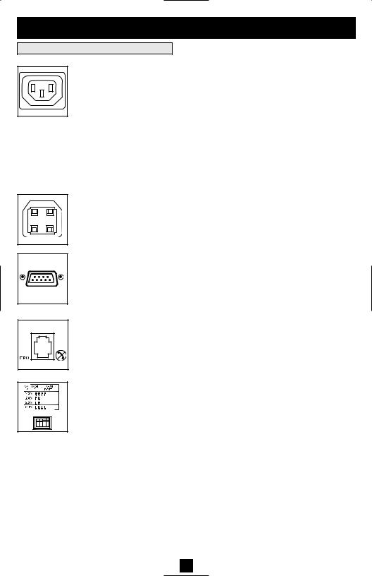
IEC320- |
C13/230V |
AC Receptacles: Your UPS features IEC320-C13 outlets. These output receptacles provide your connected equipment with AC line power during normal operation and battery power during blackouts and brownouts. The UPS protects equipment connected to these receptacles against damaging surges and line noise. If you have a serial or USB connection to your UPS, you can remotely reboot connected equipment by turning individually controllable receptacles OFF and ON using Tripp Lite's PowerAlert Software. Three receptacles, labeled LOAD 1, LOAD 2 and LOAD 3, are individually controllable and may be remotely switched OFF and ON using PowerAlert Software without interrupting power to equipment connected to other outlets. Outlets labeled UNSWITCHED may not be remotely turned off. Unswitched outlets can only be turned off by turning off all output receptacles. See software instructions for details.
Communications Ports (USB or RS-232): These ports connect your UPS to any workstation or server. Use with Tripp Lite’s PowerAlert Software and included cables to enable your computer to automatically save open files and shut down equipment during a blackout. Also use PowerAlert Software to monitor a wide variety of AC line power and UPS operating conditions. Consult your PowerAlert Software manual or contact Tripp Lite Customer Support for more information. See “USB and RS-232 Serial Communications” in the “Optional Installation” section for installation instructions.
EPO (Emergency Power Off) Port: Your UPS features a EPO port that may be used to connect the UPS to a contact closure switch to enable emergency inverter shutdown. See Optional Installation.
NO EXTERNAL |
BATTERIES |
EXTERNAL |
BATTERIES |
Voltage DIP Switches: These switches enable the UPS to be set to match actual input voltage. If the Voltage DIP Switches are set above or below input voltage, the UPS will treat the input as a continuous overvoltage or undervoltage condition, and will automatically adjust input voltage to match the Voltage DIP Switch setting. This will cause constant, unnecessary wear on the UPS.
Note: The Voltage DIP Switches must be set with the UPS turned OFF and disconnected from utility power. If the switches are set while the UPS is connected to utility power, the setting will not take effect.
9
Basic Operation continued
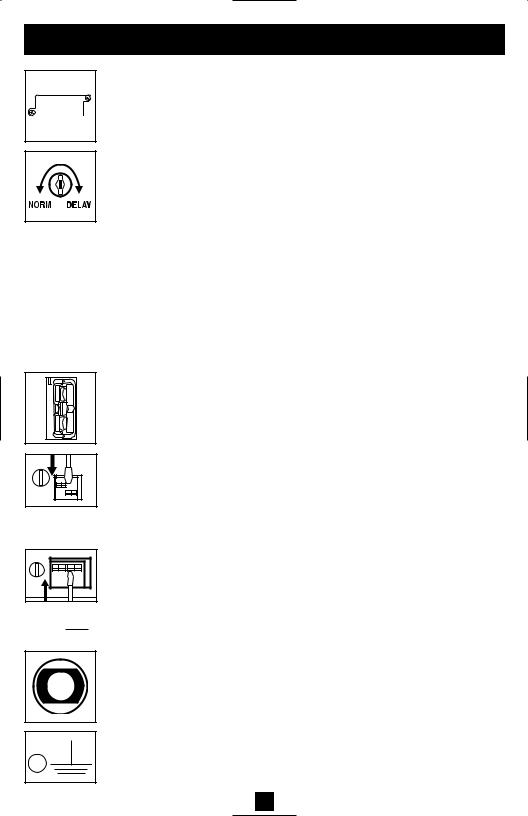
Charge Rate Setting (when External Batteries are connected)
Charge Rate Setting (when External Batteries are not connected)
Accessory Slot: Remove the small cover panel from this slot to install optional accessories to remotely monitor and control your UPS. Refer to your accessory’s manual for installation instructions. Contact Tripp Lite Customer Support at (773) 869-1234 for more information, including a list of available SNMP, network management and connectivity products.
Power Sensitivity Adjustment: This dial is normally set fully counter-clock- wise, which enables the UPS to provide maximum protection against waveform distortions in its AC input. When such distortion occurs, the UPS will normally switch to providing sine wave power from its battery reserves for as long as the distortion is present. In areas with poor utility power or where the UPS’s input power comes from a backup generator, chronic waveform distortion could cause the UPS to switch to battery too frequently, draining its battery reserves. You may be able to reduce how often your UPS switches to battery due to moderate waveform distortion by experimenting with different settings for this dial. As the dial is turned clockwise, the UPS becomes more tolerant of variations in its input power’s AC waveform. NOTE: The further the dial is adjusted clockwise, the greater the degree of waveform distortion the UPS will allow to pass to connected equipment. When experimenting with different settings for this dial, operate connected equipment in a safe test mode so that the effect on the equipment of any waveform distortions in the UPS’s output can be evaluated without disrupting critical operations.
External Battery Connector (Select Models Only): Use to connect Tripp Lite external battery packs for additional runtime. Refer to instructions available with the battery pack for complete connection information and safety warnings.
Battery Charge Level Switches (Select Models Only): Controls the UPS system’s battery charge rate. If you connect any external batteries, set the Battery Charge Level Switch to the down position. This will increase your UPS's charger output so the additional batteries charge faster.
CAUTION! DO NOT set the Battery Charge Level Switches to the down position without an external battery connected. There is a risk of damaging the UPS’s internal battery system.
Input Breaker(s) (all models): Protect your electrical circuit from overcurrent draw from the UPS load. If these breakers trip, remove some of the load, then reset them by pressing the breaker(s) in.
Ground Screw: Use this to connect any equipment that requires a chassis ground.
10
Storage and Service
Storage
Before storing your UPS, turn it completely OFF: with the UPS ON and receiving utility power, press and hold the “ON/OFF/STANDBY” button for one second (an alarm will beep once briefly after the interval has passed); then, unplug the UPS from the wall outlet. If you store your UPS for an extended period of time, recharge the UPS batteries once every three months: plug the UPS into a wall outlet; allow it to charge for 12 hours; and then unplug it and place it back in storage. Note: after you plug the UPS in, it will automatically begin charging its batteries; however, it will not supply power to its outlets (see Quick Installation section). If you leave your UPS batteries discharged for an extended period of time, they will suffer a permanent loss of capacity.
Service
Before returning your UPS for service, follow these steps:
1.Review the installation and operation instructions in this manual to ensure that the service problem does not originate from a misreading of the instructions. Also, check that the UPS System’s circuit breaker(s) are not tripped. This is the most common cause of service inquiries which can be easily remedied by following the resetting instructions in this manual.
2.If the problem continues, do not contact or return the UPS to the dealer. Instead, call Tripp Lite at (773) 869-1233. A service technician will ask for the UPS's model number, serial number and purchase date and will attempt to correct the problem over the phone.
3.If the problem requires service, the technician will issue you a Returned Material Authorization (RMA) number, which is required for service. If you require packaging, the technician can arrange to send you proper packaging. Securely pack the UPS to avoid damage during shipping. Do not use Styrofoam beads for packaging. Any damages (direct, indirect, special, incidental or consequential) to the UPS incurred during shipment to Tripp Lite or an authorized Tripp Lite service center is not covered under warranty. UPS Systems shipped to Tripp Lite or an authorized Tripp Lite service center must have transportation charges prepaid. Mark the RMA number on the outside of the package. If the UPS System is within the 2-year warranty period, enclose a copy of your sales receipt. Return the UPS for service using an insured carrier to the address given to you by the Tripp Lite service technician.
11

Battery Replacement
Under normal conditions, the original batteries in your UPS will last many years. See Safety section before replacing batteries. The batteries are designed for hot-swap replacement (i.e. leaving the UPS in ON mode), but some qualified service personnel may wish to put the UPS in the OFF mode and disconnect equipment before proceeding.
Procedure
1Remove Front Panel
2Disconnect Batteries
3Remove/Dispose of Batteries
4Add Batteries
5Connect Batteries
Attach connectors: black-to-black and red-to-red.
6 Replace Front Panel
|
SMARTPRO UPS |
1 |
|
6 |
2 |
|
5 |
3 |
4 |
Regulatory Compliance Identification Numbers
For the purpose of regulatory compliance certifications and identification, your Tripp Lite product has been assigned a unique series number. The series number can be found on the product nameplate label, along with all required approval markings and information. When requesting compliance information for this product, always refer to the series number. The series number should not be confused with the marking name or model number of the product.
This product designed and engineered in the USA.
Note on Labeling
Two symbols are used on the label.
V~ : AC Voltage
V : DC Voltage
12

Manual del propietario
SmartPro®
Sistema de UPS, Inteligentes y Interactivos en Línea
• 220/230/240V entrada/salida de onda sinusoidal • Tiempo de respaldo extendido Modelo: SMX2200XLRT2U
No conveniente para los usos móviles
|
|
|
|
|
|
|
|
|
|
|
|
|
|
|
|
|
|
|
|
|
|
|
|
|
|
|
|
|
|
|
|
|
|
|
|
|
|
|
|
|
|
|
|
|
|
|
|
|
|
|
|
|
|
|
|
|
|
|
|
|
|
|
|
|
|
|
|
|
|
|
|
|
|
|
|
|
|
|
|
|
|
|
|
|
|
|
|
|
|
|
|
|
|
|
|
|
|
|
|
|
|
|
|
|
|
|
|
|
|
|
|
|
|
|
|
|
|
|
|
|
|
|
|
|
|
|
|
|
|
|
|
|
|
|
|
|
|
|
|
|
|
|
|
|
|
|
|
|
|
|
|
|
|
|
|
|
|
|
|
|
|
|
|
|
|
|
|
|
|
|
|
|
|
|
|
|
|
|
|
|
|
|
|
|
|
|
|
|
|
|
|
|
|
|
|
|
|
Instrucciones de seguridad importantes |
14 |
||||||||||||||||
|
|
|
|
|
|
|
|
|
|
|
|
|
|
|
|
|
|
Montaje |
15 |
||||||||||||||||
|
|
|
|
|
|
|
|
|
|
|
|
|
|
|
|
|
|
|
|
|
|
|
|
|
|
|
|
|
|
|
|
|
|
|
|
Instalación rápida |
17 |
||||||||||||||||
|
|
|
|
|
|
|
|
|
|
|
|
|
|
|
|
|
|
|
|
|
|
|
|
|
|
|
|
|
|
|
|
|
|
|
|
Instalación opcional |
18 |
||||||||||||||||
|
|
|
|
|
|
|
|
|
|
|
|
|
|
|
|
|
|
Operación básica |
19 |
||||||||||||||||
|
|
|
|
|
|
|
|
|
|
|
|
|
|
|
|
|
|
|
|
|
|
|
|
|
|
|
|
|
|
|
|
|
|
|
|
Almacenamiento y servicio |
23 |
||||||||||||||||
|
|
|
|
|
|
|
|
|
|
|
|
|
|
|
|
|
|
|
|
|
|
|
|
|
|
|
|
|
|
|
|
|
|
|
|
Reemplazo de batería |
24 |
||||||||||||||||
|
|
|
|
|
|
|
|
|
|
|
|
|
|
|
|
|
|
|
|
|
|
|
|
|
|
|
|
|
|
|
|
|
|
|
|
English |
1 |
||||||||||||||||
|
|
||||||||||||||||
Français |
25 |
||||||||||||||||
|
|
||||||||||||||||
|
|
||||||||||||||||
Deutsch |
37 |
||||||||||||||||
|
|
||||||||||||||||
PyccŞèé |
49 |
||||||||||||||||
|
|
|
|
|
|
|
|
|
|
|
|
|
|
|
|
|
|
1111 W. 35th Street Chicago, IL 60609 USA Soporte al cliente: (773) 869-1234 • www.tripplite.com
Copyright ©2006 Tripp Lite. Todos los derechos reservados. SmartPro® es una marca comercial registrada de Tripp Lite.

Instrucciones de seguridad importantes
GUARDE ESTAS INSTRUCCIONES
Este manual contiene importantes instrucciones que deben seguirse durante la instalación, operación y el almacenamiento de todos los UPS de Tripp Lite. La no observancia de estas advertencias anulará su garantía.
Advertencias sobre la ubicación del UPS
•Tenga cuidado al levantar el UPS. Debido al gran peso de los UPS para montaje en bastidor, se requieren por lo menos dos personas para que le ayuden a levantarlos e instalarlos.
•Instale su UPS bajo techo, lejos de la humedad, el calor, el polvo o la luz solar directa.
•Para un mejor funcionamiento, la temperatura ambiente cerca de su UPS debe estar entre 0° C y 40° C (32° F - 104° F)
•Deje una cantidad adecuada de espacio alrededor de todos los lados del UPS para sua adecuada ventilación. No obstruya sus respiraderos ni las aberturas de ventilación.
Advertencias sobre la conexión del UPS
•El UPS contiene su propia fuente de energía (batería) Los terminales de salida pueden estar con energía incluso cuando el UPS no está conectado a un suministro de corriente alterna.
•Conecte su UPS a una toma de CA puesta a tierra apropiadamente. No modifique el enchufe del UPS en ninguna forma que elimine su conexión a tierra. No use adaptadores que eliminen la conexión del UPS a tierra.
•No conecte el UPS a si mismo ya que podría dañarse y anular la garantía.
•Si va a conectar su UPS a un generador de corriente alterna accionado por un motor, el generador debe suministrar una salida filtrada, con regulación por frecuencia grado computadora. La conexión de su UPS a un generador anulará su seguro Ultimate de por vida.
Advertencias sobre la conexión de equipos
•No utilice sistemas UPS de Tripp Lite para aplicaciones de soporte de vida en las que un funcionamiento defectuoso o una falla del UPS pudiera causar un mal funcionamiento o una alteración importante en el funcionamiento de un dispositivo de soporte de vida.
•No conecte supresores de sobretensiones ni cordones de extensión a la salida de su UPS. Esto puede sobrecargarlo y anular su garantía y la del supresor de sobretensiones.
Advertencias sobre la batería
•Las baterías presentan un peligro de choque eléctrico y quemaduras debido a las altas corrientes de cortocircuito. Observe las precauciones apropiadas. No deseche las baterías en un incinerador. No abra el UPS ni las baterías. No ponga los terminales de la batería en corto o en puente con ningún objeto. Apague y desconecte el UPS antes de reemplazar la batería. Use herramientas con mangos aislados. No hay piezas que el usuario pueda reparar dentro del UPS. El reemplazo de baterías debe ser realizado solamente por personal de servicio autorizado usando el mismo número y tipo de baterías (plomo-ácido, selladas). Las baterías son reciclables. Consulte la reglamentación local para los requisitos de disposición de desechos. Tripp Lite ofrece una línea completa de cartuchos de reemplazo de batería para UPS (R.B.C.) Visite la página web de Tripp Lite en www.tripplite.com para localizar la batería de reemplazo específica para su UPS.
•Durante el reemplazo de baterías en operación (hot-swap), el UPS no proporcionará energía de respaldo en el caso de una falla del servicio eléctrico u otras interrupciones de energía.
•No opere el UPS sin baterías.
•Al agregar bancos de baterías externas a modelos exclusivos con conectores para este tipo de bancos, sólo emplee bancos recomendados por Tripp Lite del voltaje y tipo correctos. No conecte ni desconecte bancos de baterías cuando el UPS esté funcionando con energía de las baterías.
14
Montaje (Bastidor)
Monte su equipo en un bastidor de 2 o 4 postes (vea la siguiente página para información sobre el montaje de 2 postes) El usuario debe determinar la idoneidad de los materiales y accesorios, así como de los procedimientos antes del montaje. Si los materiales y procedimientos no son adecuados para su aplicación, contacte con el fabricante de su bastidor. Los procedimientos descritos en este manual son para bastidores comunes y de tipo caja y podrían no ser apropiados para todas las aplicaciones.
Montaje de 4 postes
1Conecte los dos segmentos de cada anaquel A usando los tornillos y las tuercas de mariposa B incluidos. Deje los tornillos ligeramente flojos de modo que los anaqueles puedan ajustarse en el siguiente paso.
2Ajuste cada anaquel para que se adapte a su bastidor, y luego instálelos en el espacio más bajo disponible del mismo con las tuercas, las arandelas y los tornillos suministrados C . Note que los bordes de apoyo deben mirar hacia adentro.
Apriete los tornillos que conectan los segmentos de los anaqueles B .
3Fije las orejas de montaje D a los agujeros de montaje de la parte delantera de su equipo E usando los tornillos suministrados F . Las orejas deben mirar hacia adelante.
4Con la ayuda de otra persona si fuera necesario, levante su equipo y deslícelo en los anaqueles de montaje. Fije su equipo al bastidor usando los accesorios suministrados G a través de las orejas de montaje y dentro de los rieles del bastidor.
B |
A |
1 |
C |
B |
2 |
E |
D |
F |
3 |
|
G |
|
4 |
|
Montaje de 2 postes (Telecomunicaciones)
Si desea montar su no-break en un bastidor de 2 postes, necesitará un juego de instalación para montaje en bastidor de 2 postes de Tripp Lite (Modelo: 2POSTRMKITWM, vendido por separado). Consulte el manual de propietario del 2POSTRMKITWM para obtener los procedimientos específicos de instalación.
15
Montaje (En torre)
Monte todos los modelos de UPS en una posición vertical, de torre, usando los accesorios incluidos. El usuario debe determinar la idoneidad de los materiales y accesorios así como de los procedimientos antes del montaje.
1Coloque su UPS sobre la parte lateral y con el panel LED/de control en la parte superior. Fije una oreja de montaje A del bastidor a cada lado del UPS usando los tornillos B incluidos. Fije las orejas de montaje del bastidor al piso con accesorios suministrados por el usuario.
2Gire el panel LED/de control para su mejor visibilidad mientras el UPS está montado en torre. Introduzca un pequeño destornillador u otra herramienta en las ranuras en cualquier lado del panel. Saque el panel, gírelo y colóquelo en posición nuevamente.
B |
A |
1 |
2
16
|
Instalación rápida |
|
1 |
Con el no-break desconectado de la |
BATTERIES |
|
energía de la red, use una herramienta |
|
|
pequeña para ajustar el conmutador DIP |
|
|
de voltaje de modo que coincida con su |
|
|
voltaje de entrada (El no-break está |
|
|
prefijado a un valor de 230 V). |
|
2 |
Introduzca un cordón de alimentación |
1 |
|
||
|
suministrado por el usuario (con un |
|
|
enchufe específico del país) en una |
|
|
toma de entrada de CA IEC-320-C20 del |
|
|
UPS. Enchufe el cordón en una toma de |
|
|
corriente alterna de la red.* |
|
|
NOTA! Después de conectar el UPS en una toma de corri- |
|
|
ente alterna con energía, el equipo (en modo "Standby") |
2 |
|
cargará automáticamente sus baterías,** pero no suminis- |
|
|
trará energía a sus salidas hasta que sea encendido (vea |
|
|
más abajo el Paso 3) |
|
|
* El único diodo o indicador iluminado sera el de recargo de batería. |
|
3 Busque uno de los cables eléctricos |
|
|
|
quevienen con el UPS. Inserte el |
|
|
enchufehembra en la toma eléctrica de |
|
|
entradaC.A.del ordenador.Inserte el |
3 |
|
enchufemacho en cualquiera de los |
|
|
|
|
|
receptácu-los de salida del UPS. |
|
4 Enchufe su equipo en el UPS.*
Repita el procedimiento 3 mencionado arriba usando losdemás cables eléctricos que se adjuntaron con el UPS.
*Su UPS ha sido diseñado para apoyar su equipo de ordenadoressolamente. Usted sobrecargará el UPS si el total del índice de losvoltios/ amperios para todo el equipo excede la capacidad de salidadel UPS (ver especificaciones). Para averiguar el índice devoltios/amperios de su equipo, búsquelos en la placa del fabricante.Siel equipo está enumerado en amperios, multiplique el número deamperios por 240 para determinar los voltios/amperios (Por ejemplo:1 amp x 240 = 240 voltios/amperios). Si no está seguro de habersobrecargado las tomas eléctricas del UPS, vea la descripción sobreel indicador “NIVELDE SOBRECARGADE SALIDA”.
5 Encienda el UPS.
Presione y mantenga presionado el botón “ON/OFF/STANDBY”(Encendido/Apagado/Reserva) durante un segundo. La alar-ma emitirá un pitido brevemente después de pasado unsegundo. Suelte el botón.
4 |
5 |
17
Instalación opcional
Estas conexiones son opcionales. Su UPS funcionará correctamente sin ellas. Nota: Modelo SMART3000RM2U mostrado en todos los diagramas.
1 Comunicaciones USB y serie RS-232 (todos los modelos)
Use el cable USB incluido (vea 1a ) y/o el cable serie DB9 (vea 1b ) para conectar el puerto de comunicaciones de su computadora al puerto de comunicaciones de su UPS. Instale en su computadora el software PowerAlert de Tripp Lite apropiado para su sistema operativo. Su UPS puede tener puertos adicionales de comunicaciones; estos puertos también pueden estar conectados a computadoras adicionales con el software PowerAlert instalado. Consulte su manual de PowerAlert para mayor información.
2 Conexión de puerto EPO (todos los modelos)
Esta característica opcional es sólo para aquellas aplicaciones que requieran una conexión al circuito de desconexión de emergencia (EPO) de la instalación Cuando el UPS está conectado a este circuito, permite el apagado de emergencia del inversor del UPS.
Usando el cable suministrado, conecte el puerto EPO de su
UPS (vea 2a ) a un contacto normalmente cerrado o normalmente abierto suministrado por el usuario, de acuerdo con el
diagrama del circuito (vea 2b ) El puerto EPO no es un supresor de sobretensiones de línea telefónica; no conecte una línea telefónica en este puerto.
3 Conexión de batería externa
Su UPS incluye un robusto sistema de batería interna; las baterías externas sólo son necesarias para prolongar el tiempo de respaldo.Al agregar baterías externas, aumentará el tiempo de recarga así como el tiempo de respaldo.
La ilustración (vea 3a ) muestra la ubicación del conector de batería externa de su UPS donde debe introducir el cable del banco de baterías. Vea las instrucciones completas de instalación para su banco de baterías en el manual del propietario del banco de baterías. Asegúrese que los cables estén introducidos completamente en sus conectores. Durante la conexión de la batería pueden producirse pequeñas chispas; esto es normal.
No conecte ni desconecte bancos de baterías cuando el UPS esté funcionando con energía de las baterías.
Si conecta alguna batería externa, fije el Interruptores de
nivel de carga de batería (via 3b ) en la posición de abajo. Esto aumentará la salida del cargador del UPS a fin de que baterías adicionales se carguen más rápido.
¡PRECAUCIÓN! NO fije el Interruptores de nivel de carga de batería en la posición de abajo sin una batería externa conectada. Podría dañar el sistema de la batería interna del UPS.
1a |
1b |
2a |
4-5 |
2b |
3a |
EXTERNAL |
BATTERIES |
3b |
18
 Loading...