


Tripp Lite PDU3EVN3L2130, PDU3EVN10L2130, PDU3EVN3L2120, PDU3EVN6L2120, PDU3EVN10L2120 Users guide
...Owner’s Manual
3-Phase Monitored & Switched
0U Power Distribution Units
(Phase, Bank, Outlet Measurements*)
208V MONITORED MODELS |
SERIES NO. |
PDU3EVN3L2130 |
AG-00B9 |
PDU3EVN10L2130 |
AG-00B9 |
PDU3EVN3L2120 |
AG-00B8 |
PDU3EVN6L2120 |
AG-00B8 |
PDU3EVN10L2120 |
AG-00B8 |
PDU3EVN6L2130 |
AG-00B9 |
208V SWITCHED MODELS |
SERIES NO. |
PDU3EVSR6G60A |
AG-0063 |
PDU3EVSR6H50A |
AG-0065 |
200 – 240V MONITORED MODELS |
SERIES NO. |
PDU3EVN6G30B |
AG-00BA |
PDU3EVN10G30B |
AG-00BA |
PDU3EVN3G60B |
AG-00BA |
PDU3EVN6G60B |
AG-00BA |
PDU3EVN10G60B |
AG-00BA |
PDU3EVN3H50B |
AG-00BA |
PDU3EVN6H50B |
AG-00BA |
PDU3EVN6H50BA |
AG-00BA |
PDU3EVN10H50B |
AG-00BA |
PDU3EVN3L1520 |
AG-00BA |
PDU3EVN6L1520 |
AG-00BA |
PDU3EVN10L1520 |
AG-00BA |
PDU3EVN3L1530B |
AG-00BA |
PDU3EVN6L1530B |
AG-00BA |
PDU3EVN10L1530B |
AG-00BA |
PDU3EVN3L2130B |
AG-00BA |
PDU3EVN6L2130B |
AG-00BA |
PDU3EVN10L2130B |
AG-00BA |
PDU3EVN2 |
AG-00BA |
PDU3EVN6G60C |
AG-00BB |
200 – 240V SWITCHED MODELS |
SERIES NO. |
PDU3EVSR6H50 |
AG-00BA |
PDU3EVSR10H50 |
AG-00BA |
PDU3EVSR6L1530 |
AG-00BA |
PDU3EVSR10L1530 |
AG-00BA |
PDU3EVSR6L2130 |
AG-00BA |
PDU3EVSR6G60 |
AG-00BA |
PDU3EVSR10L2130 |
AG-00BA |
PDU3EVS6H50 |
AG-00BA |
PDU3EVS6L2130 |
AG-00BA |
PDU3EVS6L2120 |
AG-00BC |
PDU3EVSR6L2120 |
AG-00BC |
PDU3EVSR6L1520 |
AG-00BC |
380 – 415V MONITORED MODELS |
SERIES NO. |
PDU3XEVN6G20 |
AG-00BD |
380 – 415V SWITCHED MODELS |
SERIES NO. |
PDU3XEVSR6G20 |
AG-00BD |
PDU3XEVSR6G30A |
AG-0096 |
PDU3XEVSR6G30B |
AG-0096 |
PDU3XEVSR6G32A |
AG-0080 |
PDU3XEVSR6G32B |
AG-0080 |
PDU3XEVSR6G60A |
AG-0093 |
PDU3XEVSR6G60B |
AG-0093 |
PDU3XEVSR6G63A |
AG-0094 |
PDU3XEVSR6G63B |
AG-0094 |
PDU3XEVSR6L230B |
AG-0056 |
PDU3XEVSR6L2230 |
AG-0056 |
PDU3XEVSRHWA |
AG-0057 |
PDU3XEVSRHWB |
AG-0057 |
*Varies by product. |
|
Español 18 • Français 35 • Русский 52
WARRANTY REGISTRATION
Register your product today and be automatically entered to win an ISOBAR surge protector in our monthly drawing!
tripplite.com/warranty
1111 W. 35th Street, Chicago, IL 60609 USA • tripplite.com/support
Copyright © 2020 Tripp1Lite. All rights reserved.

Important Safety Instructions
SAVE THESE INSTRUCTIONS
This manual contains instructions and warnings that should be followed during the installation, operation, and storage of this product. Failure to heed these instructions and warnings may affect the product warranty.
•The PDU provides the convenience of multiple outlets, but DOES NOT provide surge or line noise protection for connected equipment.
•The PDU is designed for indoor use only, in a controlled environment, away from excess moisture, temperature extremes, conductive contaminants, dust or direct sunlight.
•Keep indoor ambient temperature between 32°F and 122°F (0°C and 50°C).
•The PDU must be installed by a qualified technician only.
•Do not attempt to mount the PDU to an insecure or unstable surface.
•Install in accordance with National Electrical Code standards. Be sure to use the proper overcurrent protection for the installation, in accordance with the plug/equipment rating.
•Connect the PDU to an outlet that is in accordance with your local building codes and that is adequately protected against excess currents, short circuits and earth faults.
•The electrical outlets supplying power to the equipment should be installed near the equipment and easily accessible.
•Do not connect the PDU to an ungrounded outlet or to extension cords or adapters that eliminate the connection to ground.
•Be sure to provide a local disconnect device on any models that are permanently installed without a plug that is easily accessible.
•Never attempt to install electrical equipment during a thunderstorm.
•Individual equipment connected to the PDU should not draw more current than the individual PDU’s outlet’s rating.
•The total load connected to the PDU must not exceed the maximum load rating for the PDU.
•Do not attempt to modify the PDU, input plugs or power cables.
•Do not drill into or attempt to open any part of the PDU housing. There are no user-serviceable parts inside.
•Do not attempt to use the PDU if any part of it becomes damaged.
•Use of this equipment in life support applications where failure of this equipment can reasonably be expected to cause the failure of the life support equipment or to significantly affect its safety or effectiveness is not recommended.
2

Installation
Mounting the PDU
Note: The illustrations may differ somewhat from your PDU model. Regardless of configuration, the user must determine the fitness of hardware and procedures before mounting. The PDU and included hardware are designed for common rack and rack enclosure types and may not be appropriate for all applications. Exact mounting configurations may vary. Screws for attaching the mounting brackets to the PDU are included. Use only the screws supplied by the manufacturer or their exact equivalent.
Note: Mounting buttons come preinstalled to the PDU for toolless mounting.
1-1 To attach the mounting brackets to the PDU, remove the mounting buttons.
1-2 Attach the mounting brackets to the PDU with the included screws.
1-3 Attach the PDU to a vertical rail in your rack or rack enclosure. (Use the
mounting hardware that came with your rack or rack enclosure to attach the mounting brackets to the rail.)
1-4 To reinstall the mounting buttons for toolless mounting, remove the mounting brackets then install the mounting buttons onto the PDU. Position the PDU as desired in the rack enclosure, align the buttons with the rack mounting slots, and slide the PDU into position.
Note: Be sure to insert the 2 buttons into either the upper hole at each end of the PDU or into the lower hole at each end of the PDU.
1-5 To install the PDU with its outlets facing the rear of the rack, use the included PDUMVROTATEBRKT accessory. First, attach the mounting button A to the V-shaped bracket B using the included screw and washer. Then, use the button-mount slot to attach the bracket to the PDU and the mounting button to attach the PDU to the rack. The bracket effectively repositions the mounting brackets allowing for the PDU outlets to face the rear of the rack.
1-1 |
1-2 |
1-3
1-4
B
A
1-5
3

Installation
Connecting the PDU
2-1 Each model is equipped with 1 of 8 different input plugs.
L15-20P |
L15-30P |
|
L21-20P |
L21-30P |
L22-30P |
Hubbell CS8365C |
||
|
|
|
|
|
|
|
|
|
|
|
|
|
|
|
|
|
|
IEC 309 |
IEC 309 |
IEC 309 |
|
IEC 309 |
|
IEC 309 |
||
30A Blue |
60A Blue |
32A Red |
|
63A Red |
|
60A Blue |
||
(3P + E) |
(3P + E) |
(3P + N + E) |
|
(3P + N + E) |
(3P + N + E) |
|||
|
|
|
|
|
|
|
|
|
|
|
Max Input |
|
|
|
|
|
|
|
|
Amps (Limited |
Input |
Output |
|
|
|
|
208V |
|
by Input Cord |
Voltage |
Voltage |
|
Cord |
|
|
Monitored Models |
Input Plug |
and Plug) |
Range |
Range |
Breakers |
Length |
Outlets |
|
|
|
|
|
|
|
|
|
|
|
|
|
|
|
3 x Double Pole, |
3 ft. |
36 x C13; |
|
PDU3EVN3L2130 |
L21-30P |
24A |
208V |
208V |
6 x C19; |
|||
20A Branch-Rated |
(0.9 m) |
|||||||
|
|
|
|
|
3 x 5-15/20R |
|||
|
|
|
|
|
|
|
||
|
|
|
|
|
|
|
|
|
|
|
|
|
|
3 x Double Pole, |
10 ft. |
36 x C13; |
|
PDU3EVN10L2130 |
L21-30P |
24A |
208V |
208V |
6 x C19; |
|||
20A Branch-Rated |
(3 m) |
|||||||
|
|
|
|
|
3 x 5-15/20R |
|||
|
|
|
|
|
|
|
||
|
|
|
|
|
|
|
|
|
PDU3EVN3L2120 |
L21-20P |
16A |
208V |
208V |
N/A |
3 ft. |
42 X C13; |
|
(0.9 m) |
6 X C19 |
|||||||
|
|
|
|
|
|
|||
|
|
|
|
|
|
|
|
|
PDU3EVN6L2120 |
L21-20P |
16A |
208V |
208V |
N/A |
6 ft. |
42 X C13; |
|
(1.8 m) |
6 X C19 |
|||||||
|
|
|
|
|
|
|||
|
|
|
|
|
|
|
|
|
PDU3EVN10L2120 |
L21-20P |
16A |
208V |
208V |
N/A |
10 ft. |
42 X C13; |
|
(3 m) |
6 X C19 |
|||||||
|
|
|
|
|
|
|||
|
|
|
|
|
|
|
|
|
|
|
|
|
|
3 x Double Pole, |
6 ft. |
36 x C13; |
|
PDU3EVN6L2130 |
L21-30P |
24A |
208V |
208V |
6 x C19; |
|||
20A Branch-Rated |
(1.8 m) |
|||||||
|
|
|
|
|
3 x 5-15/20R |
|||
|
|
|
|
|
|
|
||
|
|
|
|
|
|
|
|
|
|
|
Max Input |
|
|
|
|
|
|
|
|
Amps (Limited |
Input |
Output |
|
|
|
|
208V |
|
by Input Cord |
Voltage |
Voltage |
|
Cord |
|
|
Switched Models |
Input Plug |
and Plug) |
Range |
Range |
Breakers |
Length |
Outlets |
|
|
|
|
|
|
|
|
|
|
|
|
|
|
|
6 x Low-Profile |
|
|
|
|
IEC 309 60A Blue |
|
|
|
with Safety Lock, |
6 ft. |
6 x C13; |
|
PDU3EVSR6G60A |
45A |
208V |
208V |
Double Pole, |
||||
(3P + E); IP44 |
(1.8 m) |
12 x C19 |
||||||
|
|
|
|
Magnetic, |
||||
|
|
|
|
|
|
|
||
|
|
|
|
|
Branch-Rated |
|
|
|
|
|
|
|
|
|
|
|
|
|
|
|
|
|
6 x Low-Profile |
|
|
|
|
IEC 309 60A Blue |
|
|
|
with Safety Lock, |
6 ft. |
6 x C13; |
|
PDU3EVSR6G60A |
(3P + N + E), IP67 |
45A |
208V |
208V |
Double Pole, |
|||
(1.8 m) |
12 x C19 |
|||||||
|
N Not Used |
|
|
|
Magnetic, |
|||
|
|
|
|
|
|
|||
|
|
|
|
|
Branch-Rated |
|
|
|
|
|
|
|
|
|
|
|
|
|
|
|
|
|
6 x Low-Profile |
|
|
|
|
|
|
|
|
with Safety Lock, |
6 ft. |
6 x C13; |
|
PDU3EVSR6H50A |
Hubbell CS8365C |
40A |
208V |
208V |
Double Pole, |
|||
(1.8 m) |
12 x C19 |
|||||||
|
|
|
|
|
Magnetic, |
|||
|
|
|
|
|
|
|
||
|
|
|
|
|
Branch-Rated |
|
|
|
|
|
|
|
|
|
|
|
|
4

Installation
|
|
Max Input |
|
|
|
|
|
|
|
|
|
Amps (Limited |
Input |
Output |
|
|
|
|
|
200 – 240V |
|
by Input Cord |
Voltage |
Voltage |
|
|
Cord |
|
|
Monitored Models |
Input Plug |
and Plug) |
Range |
Range |
|
Breakers |
Length |
Outlets |
|
|
|
|
|
|
|
|
|
||
PDU3EVN6G30B |
IEC 309 30A Blue |
24A |
200- |
200- |
3 x Double Pole, |
6 ft. |
42 x C13; |
||
(3P + E); IP44 |
240V |
240V |
20A |
Branch-Rated |
(1.8 m) |
6 x C19 |
|||
|
|
||||||||
|
|
|
|
|
|
|
|
||
PDU3EVN10G30B |
IEC 309 30A Blue |
24A |
200- |
200- |
3 x Double Pole, |
10 ft. |
42 x C13; |
||
(3P + E); IP44 |
240V |
240V |
20A |
Branch-Rated |
(3 m) |
6 x C19 |
|||
|
|
||||||||
|
|
|
|
|
|
|
|
||
PDU3EVN3G60B |
IEC 309 60A Blue |
35A |
200- |
200- |
3 x Double Pole, |
3 ft. |
42 x C13; |
||
(3P + E); IP44 |
240V |
240V |
20A |
Branch-Rated |
(0.9 m) |
6 x C19 |
|||
|
|
||||||||
|
|
|
|
|
|
|
|
||
PDU3EVN6G60B |
IEC 309 60A Blue |
35A |
200- |
200- |
3 x Double Pole, |
6 ft. |
42 x C13; |
||
(3P + E); IP44 |
240V |
240V |
20A |
Branch-Rated |
(1.8 m) |
6 x C19 |
|||
|
|
||||||||
|
|
|
|
|
|
|
|
||
PDU3EVN10G60B |
IEC 309 60A Blue |
35A |
200- |
200- |
3 x Double Pole, |
10 ft. |
42 x C13; |
||
(3P + E); IP44 |
240V |
240V |
20A |
Branch-Rated |
(3 m) |
6 x C19 |
|||
|
|
||||||||
|
|
|
|
|
|
|
|
||
PDU3EVN3H50B |
Hubbell CS8365C |
35A |
200- |
200- |
3 x Double Pole, |
3 ft. |
42 x C13; |
||
240V |
240V |
20A |
Branch-Rated |
(0.9 m) |
6 x C19 |
||||
|
|
|
|||||||
|
|
|
|
|
|
|
|
||
PDU3EVN6H50B |
Hubbell CS8365C |
35A |
200- |
200- |
3 x Double Pole, |
6 ft. |
42 x C13; |
||
240V |
240V |
20A |
Branch-Rated |
(1.8 m) |
6 x C19 |
||||
|
|
|
|||||||
|
|
|
|
|
|
|
|
||
PDU3EVN6H50BA |
Hubbell CS8365C |
35A |
200- |
200- |
3 x Double Pole, |
6 ft. |
30 x C13; |
||
240V |
240V |
20A |
Branch-Rated |
(1.8 m) |
12 x C19 |
||||
|
|
|
|||||||
|
|
|
|
|
|
|
|
||
PDU3EVN10H50B |
Hubbell CS8365C |
35A |
200- |
200- |
3 x Double Pole, |
10 ft. |
42 x C13; |
||
240V |
240V |
20A Branch-Rated |
(3 m) |
6 x C19 |
|||||
|
|
|
|||||||
|
|
|
|
|
|
|
|
|
|
PDU3EVN3L1520 |
L15-20 |
16A |
200- |
200- |
|
— |
3 ft. |
42 x C13; |
|
240V |
240V |
|
(0.9 m) |
6 x C19 |
|||||
|
|
|
|
|
|||||
|
|
|
|
|
|
|
|
|
|
PDU3EVN6L1520 |
L15-20 |
16A |
200- |
200- |
|
— |
6 ft. |
42 x C13; |
|
240V |
240V |
|
(1.8 m) |
6 x C19 |
|||||
|
|
|
|
|
|||||
|
|
|
|
|
|
|
|
|
|
PDU3EVN10L1520 |
L15-20 |
16A |
200- |
200- |
|
— |
10 ft. |
42 x C13; |
|
240V |
240V |
|
(3 m) |
6 x C19 |
|||||
|
|
|
|
|
|||||
|
|
|
|
|
|
|
|
||
PDU3EVN3L1530B |
L15-30P |
24A |
200- |
200- |
3 x Double Pole, |
3 ft. |
42 x C13; |
||
240V |
240V |
20A Branch-Rated |
(0.9 m) |
6 x C19 |
|||||
|
|
|
|||||||
|
|
|
|
|
|
|
|
||
PDU3EVN6L1530B |
L15-30P |
24A |
200- |
200- |
3 x Double Pole, |
6 ft. |
42 x C13; |
||
240V |
240V |
20A Branch-Rated |
(1.8 m) |
6 x C19 |
|||||
|
|
|
|||||||
|
|
|
|
|
|
|
|
||
PDU3EVN10L1530B |
L15-30P |
24A |
200- |
200- |
3 x Double Pole, |
10 ft. |
42 x C13; |
||
240V |
240V |
20A Branch-Rated |
(3 m) |
6 x C19 |
|||||
|
|
|
|||||||
|
|
|
|
|
|
|
|
||
PDU3EVN3L2130B |
L21-30P |
24A |
200- |
200- |
3 x Double Pole, |
3 ft. |
42 x C13; |
||
240V |
240V |
20A Branch-Rated |
(0.9 m) |
6 x C19 |
|||||
|
|
|
|||||||
|
|
|
|
|
|
|
|
||
PDU3EVN6L2130B |
L21-30P |
24A |
200- |
200- |
3 x Double Pole, |
6 ft. |
42 x C13; |
||
240V |
240V |
20A Branch-Rated |
(1.8 m) |
6 x C19 |
|||||
|
|
|
|||||||
|
|
|
|
|
|
|
|
||
PDU3EVN10L2130B |
L21-30P |
24A |
200- |
200- |
3 x Double Pole, |
10 ft. |
42 x C13; |
||
240V |
240V |
20A Branch-Rated |
(3 m) |
6 x C19 |
|||||
|
|
|
|||||||
|
|
|
|
|
|
|
|
||
PDU3EVN2 |
Hardwire |
35A |
200- |
200- |
3 x Double Pole, |
N/A |
42 x C13; |
||
240V |
240V |
20A Branch-Rated |
6 x C19 |
||||||
|
|
|
|
||||||
|
|
|
|
|
|
|
|
||
|
|
|
|
|
6 x Low-Profile |
|
|
||
|
IEC 309 60A Blue |
|
200- |
200- |
with Safety Lock, |
6 ft. |
|
||
PDU3EVN6G60C |
45A |
Double Pole, |
36 x C13 |
||||||
(3P + E); IP44 |
240V |
240V |
(1.8 m) |
||||||
|
|
|
Magnetic, |
|
|||||
|
|
|
|
|
|
|
|
||
|
|
|
|
|
Branch-Rated |
|
|
||
|
|
|
|
|
|
|
|
|
|
5

Installation
|
|
Max Input |
|
|
|
|
|
|
|
|
Amps (Limited |
Input |
Output |
|
|
|
|
200 – 240V |
|
by Input Cord |
Voltage |
Voltage |
|
Cord |
|
|
Switched Models |
Input Plug |
and Plug) |
Range |
Range |
Breakers |
Length |
Outlets |
|
|
|
|
|
|
|
|
|
|
PDU3EVSR6H50 |
Hubbell CS8365C |
35A |
200- |
200- |
3 x Double Pole, |
6 ft. |
24 x C13; |
|
240V |
240V |
20A Branch-Rated |
(1.8 m) |
6 x C19 |
||||
|
|
|
||||||
|
|
|
|
|
|
|
|
|
PDU3EVSR10H50 |
Hubbell CS8365C |
35A |
200- |
200- |
3 x Double Pole, |
10 ft. |
24 x C13; |
|
240V |
240V |
20A Branch-Rated |
(3 m) |
6 x C19 |
||||
|
|
|
||||||
|
|
|
|
|
|
|
|
|
PDU3EVSR6L1530 |
L15-30P |
24A |
200- |
200- |
3 x Double Pole, |
6 ft. |
24 x C13; |
|
240V |
240V |
20A Branch-Rated |
(1.8 m) |
6 x C19 |
||||
|
|
|
||||||
|
|
|
|
|
|
|
|
|
PDU3EVSR10L1530 |
L15-30P |
24A |
200- |
200- |
3 x Double Pole, |
10 ft. |
24 x C13; |
|
240V |
240V |
20A Branch-Rated |
(3 m) |
6 x C19 |
||||
|
|
|
||||||
|
|
|
|
|
|
|
|
|
PDU3EVSR6L2130 |
L21-30P |
24A |
200- |
200- |
3 x Double Pole, |
6 ft. |
24 x C13; |
|
240V |
240V |
20A Branch-Rated |
(1.8 m) |
6 x C19 |
||||
|
|
|
||||||
|
|
|
|
|
|
|
|
|
PDU3EVSR10L2130 |
L21-30P |
24A |
200- |
200- |
3 x Double Pole, |
10 ft. |
24 x C13; |
|
240V |
240V |
20A Branch-Rated |
(3 m) |
6 x C19 |
||||
|
|
|
||||||
|
|
|
|
|
|
|
|
|
PDU3EVSR6G60 |
IEC 309 60A Blue |
35A |
200- |
200- |
3 x Double Pole, |
10 ft. |
24 x C13; |
|
(3P + E), IP44 |
240V |
240V |
20A Branch-Rated |
(3 m) |
6 x C19 |
|||
|
|
|||||||
|
|
|
|
|
|
|
|
|
|
IEC 309 60A Blue |
|
200- |
200- |
3 x Double Pole, |
10 ft. |
24 x C13; |
|
PDU3EVSR6G60 |
(3P + N + E), IP67 |
35A |
||||||
240V |
240V |
20A Branch-Rated |
(3 m) |
6 x C19 |
||||
|
N Not Used |
|
||||||
|
|
|
|
|
|
|
||
|
|
|
|
|
|
|
|
|
|
|
|
|
|
3 x Low Profile |
|
|
|
|
|
|
200- |
200- |
with Safety Lock, |
6 ft. |
24 x C13; |
|
PDU3EVS6H50 |
Hubbell CS8365C |
35A |
Double Pole, |
|||||
240V |
240V |
(1.8 m) |
6 x C19 |
|||||
|
|
|
Magnetic, |
|||||
|
|
|
|
|
|
|
||
|
|
|
|
|
Branch-Rated |
|
|
|
|
|
|
|
|
|
|
|
|
|
|
|
|
|
3 x Low Profile |
|
|
|
|
|
|
200- |
200- |
with Safety Lock, |
6 ft. |
24 x C13; |
|
PDU3EVS6L2130 |
L21-30P |
24A |
Double Pole, |
|||||
240V |
240V |
(1.8 m) |
6 x C19 |
|||||
|
|
|
Magnetic, |
|||||
|
|
|
|
|
|
|
||
|
|
|
|
|
Branch-Rated |
|
|
|
|
|
|
|
|
|
|
|
|
PDU3EVS6L2120 |
L21-20P |
16A |
200- |
200- |
— |
6 ft. |
24 x C13; |
|
240V |
240V |
(1.8 m) |
6 x C19 |
|||||
|
|
|
|
|||||
|
|
|
|
|
|
|
|
|
PDU3EVSR6L2120 |
L21-20P |
16A |
200- |
200- |
— |
6 ft. |
24 x C13; |
|
240V |
240V |
(1.8 m) |
6 x C19 |
|||||
|
|
|
|
|||||
|
|
|
|
|
|
|
|
|
PDU3EVSR6L1520 |
L15-20P |
16A |
200- |
200- |
— |
6 ft. |
24 x C13; |
|
240V |
240V |
(1.8 m) |
6 x C19 |
|||||
|
|
|
|
|||||
|
|
|
|
|
|
|
|
|
|
|
Max Input |
|
|
|
|
|
|
|
|
Amps (Limited |
Input |
Output |
|
|
|
|
380 – 415V |
|
by Input Cord |
Voltage |
Voltage |
|
Cord |
|
|
Monitored Models |
Input Plug |
and Plug) |
Range |
Range |
Breakers |
Length |
Outlets |
|
|
|
|
|
|
|
|
|
|
PDU3XEVN6G20 |
IEC 309 20A Red |
16A |
380- |
380- |
— |
6 ft. |
42 x C13; |
|
(3P + N + E); IP44 |
415V |
415V |
(1.8 m) |
6 x C19 |
||||
|
|
|
||||||
|
|
|
|
|
|
|
|
6

Installation
|
|
Max Input |
|
|
|
|
|
|
|
|
Amps (Limited |
Input |
Output |
|
|
|
|
380 – 415V |
|
by Input Cord |
Voltage |
Voltage |
|
Cord |
|
|
Switched Models |
Input Plug |
and Plug) |
Range |
Range |
Breakers |
Length |
Outlets |
|
|
|
|
|
|
|
|
|
|
PDU3XEVSR6G20 |
IEC 309 20A Red |
16A |
380- |
380- |
— |
6 ft. |
24 x C13; |
|
(3P + N + E); IP44 |
415V |
415V |
(1.8 m) |
6 x C19 |
||||
|
|
|
||||||
|
|
|
|
|
|
|
|
|
|
|
|
|
|
6 x Low-Profile |
|
|
|
|
IEC 309 32A Red |
|
380- |
380- |
with Safety Lock, |
6 ft. |
12 x C13; |
|
PDU3XEVSR6G30A |
24A |
Single Pole, |
||||||
(3P + N + E); IP44 |
415V |
415V |
(1.8 m) |
12 x C19 |
||||
|
|
Magnetic, |
||||||
|
|
|
|
|
|
|
||
|
|
|
|
|
Branch-Rated |
|
|
|
|
|
|
|
|
|
|
|
|
PDU3XEVSR6G30B |
IEC 309 32A Red |
24A |
380- |
380- |
6 x Double Pole, |
6 ft. |
24 x C13; |
|
(3P + N + E); IP44 |
415V |
415V |
20A Branch-Rated |
(1.8 m) |
6 x C19 |
|||
|
|
|||||||
|
|
|
|
|
|
|
|
|
|
|
|
|
|
6 x Low-Profile |
|
|
|
|
IEC 309 32A Red |
|
380- |
380- |
with Safety Lock, |
6 ft. |
12 x C13; |
|
PDU3XEVSR6G32A |
32A |
Single Pole, |
||||||
(3P + N + E); IP44 |
415V |
415V |
(1.8 m) |
12 x C19 |
||||
|
|
Magnetic, |
||||||
|
|
|
|
|
|
|
||
|
|
|
|
|
Branch-Rated |
|
|
|
|
|
|
|
|
|
|
|
|
PDU3XEVSR6G32B |
IEC 309 32A Red |
32A |
380- |
380- |
6 x Double Pole, |
6 ft. |
24 x C13; |
|
(3P + N + E); IP44 |
415V |
415V |
20A Branch-Rated |
(1.8 m) |
6 x C19 |
|||
|
|
|||||||
|
|
|
|
|
|
|
|
|
|
|
|
|
|
6 x Low-Profile |
|
|
|
|
IEC 309 63A Red |
|
380- |
380- |
with Safety Lock, |
6 ft. |
12 x C13; |
|
PDU3XEVSR6G60A |
35A |
Single Pole, |
||||||
(3P + N +E); IP44 |
415V |
415V |
(1.8 m) |
12 x C19 |
||||
|
|
Magnetic, |
||||||
|
|
|
|
|
|
|
||
|
|
|
|
|
Branch-Rated |
|
|
|
|
|
|
|
|
|
|
|
|
PDU3XEVSR6G60B |
IEC 309 63A Red |
35A |
380- |
380- |
6 x Double Pole, |
6 ft. |
24 x C13; |
|
(3P + N +E); IP44 |
415V |
415V |
20A Branch-Rated |
(1.8 m) |
6 x C19 |
|||
|
|
|||||||
|
|
|
|
|
|
|
|
|
|
|
|
|
|
6 x Low-Profile |
|
|
|
|
IEC 309 63A Red |
|
380- |
380- |
with Safety Lock, |
6 ft. |
12 x C13; |
|
PDU3XEVSR6G63A |
40A |
Single Pole, |
||||||
(3P + N +E); IP44 |
415V |
415V |
(1.8 m) |
12 x C19 |
||||
|
|
Magnetic, |
||||||
|
|
|
|
|
|
|
||
|
|
|
|
|
Branch-Rated |
|
|
|
|
|
|
|
|
|
|
|
|
PDU3XEVSR6G63B |
IEC 309 63A Red |
40A |
380- |
380- |
6 x Double Pole, |
6 ft. |
24 x C13; |
|
(3P + N +E); IP44 |
415V |
415V |
20A Branch-Rated |
(1.8 m) |
6 x C19 |
|||
|
|
|||||||
|
|
|
|
|
|
|
|
|
PDU3XEVSR6L230B |
L22-30P |
24A |
380- |
380- |
6 x Double Pole, |
6 ft. |
24 x C13; |
|
415V |
415V |
20A Branch-Rated |
(1.8 m) |
6 x C19 |
||||
|
|
|
||||||
|
|
|
|
|
|
|
|
|
|
|
|
|
|
6 x Low-Profile |
|
|
|
|
|
|
380- |
380- |
with Safety Lock, |
6 ft. |
12 x C13; |
|
PDU3XEVSR6L2230 |
L22-30P |
24A |
Single Pole, |
|||||
415V |
415V |
(1.8 m) |
12 x C19 |
|||||
|
|
|
Magnetic, |
|||||
|
|
|
|
|
|
|
||
|
|
|
|
|
Branch-Rated |
|
|
|
|
|
|
|
|
|
|
|
|
|
|
|
|
|
6 x Low-Profile |
|
|
|
|
|
|
380- |
380- |
with Safety Lock, |
|
12 x C13; |
|
PDU3XEVSRHWA |
Hardwire |
40A |
Single Pole, |
N/A |
||||
415V |
415V |
12 x C19 |
||||||
|
|
|
Magnetic, |
|
||||
|
|
|
|
|
|
|
||
|
|
|
|
|
Branch-Rated |
|
|
|
|
|
|
|
|
|
|
|
|
PDU3XEVSRHWB |
Hardwire |
40A |
380- |
380- |
6 x Double Pole, |
N/A |
24 x C13; |
|
415V |
415V |
20A Branch-Rated |
6 x C19 |
|||||
|
|
|
|
|||||
|
|
|
|
|
|
|
|
7

Installation
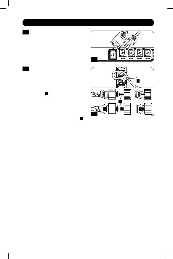
2-2A Corded Models - Connect the input plug to your facility’s compatible AC power source and input connection.
Plug type may vary by model.
2-2A
2-2B Hardwire Models (PDU3XEVSRHWA and PDU3XEVSRHWB only)
WARNING
Only qualified personnel should perform hardwire installations. Wire codes and requirements differ from area to area. Be sure to conform to local electrical requirements. Use of copper wiring with ferrules is recommended for AC input terminal connections. Each input terminal connection should be torqued to the listed specification. Improperly sized wiring, inadequate torque, or use of noncopper wiring can result in overheating of input terminal connections.
These models do not come equipped with an input cable. Conduit and adapters are installed to the endplate A , wires are channeled through the conduit and adapters to the terminal block, located behind the access plate B .
Model |
Recommended Wire Gauge / Type |
Torque Specifications |
|
PDU3XEVSRHWA |
#6 AWG Copper Wire (13.3 mm2) |
12.2 in•lbf (1.38 N•m) |
|
PDU3XEVSRHWB |
|||
|
|
To access the terminal block to make input wire connections, remove the access plate located on the rear side of the PDU C . Ferruled wire ends are recommended. Secure conduit and torque wire connections to listed torque specifications.
|
|
|
Ground Terminal |
A |
|
B |
|
|
|
X
Y
Z
N
Remove Access Plate Screws |
2-2B |
C |
8
Installation
2-3 Connect your equipment’s input plugs to the appropriate outlets on the PDU. The LED near each outlet illuminates when the outlet is ready to distribute live
AC power.
Note: It is recommended that you do not |
|
connect a live load to the PDU. If the load you |
2-3 |
intend to connect has an ON/OFF switch, please |
|
turn the switch to OFF prior to connection. |
|
2-4 Optional Cord Retention Procedure |
|
Option 1: Use the bridge lances located |
|
near each receptacle to retain power |
|
cords. Tie each equipment power cord |
|
to a bridge lance by looping the cord |
|
and securing it with one of the included |
|
cable ties A . Make sure each cord can |
|
be unplugged from the PDU without |
|
removing the cable tie. |
|
Option 2: Use the included C14 and |
|
C20 plastic sleeves to secure plugs to |
2-4 |
receptacles. Attach the sleeve to the |
plug, making sure that the pull tabs B remain outside the plug and that the fit is secure. To unplug equipment properly, use the pull tabs to remove the plug and sleeve from the receptacle.


 A
A
B
Networking the PDU
Your PDU can receive IP address assignments via DHCP server (dynamic) or static (manual) addressing methods. See the LX Platform User’s Guide for an explanation of these methods. You can find the guide by going to tripplite.com/support and typing LX Platform in the search field. If you are uncertain which method to use, contact your network administrator for assistance before continuing the configuration process.
Note: The MAC address of the PDU (12-digit string in this format: 000667xxxxxx) is printed on a label attached to the PDU enclosure.
9
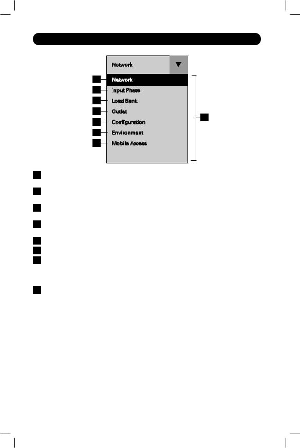
LCD Touchscreen
Network
BNetwork
CInput
 Phase
Phase
DLoad Bank
EOutlet
F |
A |
Configuration |
|
G |
Environment |
H |
Mobile Access |
AMain Menu: Use the q on the touchscreen to toggle between the main menu and the previously selected panel. Available options will vary based on the PDU and peripherals.
BNetwork: Displays the IP address, Subnet Mask, Gateway, MAC Address, Device Name, Model and Serial Number.
CInput Phase: Displays the amperage and voltage for each phase, as well as the Unbalanced Load %.
DLoad Bank: Displays the total amperage, wattage and voltage for each load bank as well as the total power in Watts.
EOutlet: Displays the amperage and wattage per outlet.
FConfiguration: Displays configurable settings for the LCD touchscreen.
GEnvironment: Displays the data and status of any EnviroSense2 (E2) modules connected to the PDU. The information shown will vary depending on the E2 model (E2MT, E2MTDI, E2MTD0, E2MTHDI). Parameters include temperature, RH% (relative humidity), and the status of input and output dry contacts (open or closed).
HMobile Access: Generates a unique QR code to view the PDU’s details on a mobile device.
10
Using the LCD Touchscreen
Scrolling Through LCD Touchscreen Options
Network
Network
Input
 Phase
Phase
Load
 Bank
Bank
Outlet
Configuration
Environment

Mobile Access
Network
Press Network on the drop down menu to view the PDU network details. Press the and
and to move between screens. Details displayed include the IP address (IP), Subnet Mask (Mask), Gateway (Gate), MAC Address (MAC), Device Name, Model and Serial Number. Press q to go back to the main menu.
After the system initializes, the Network panel will appear. Use q on the touchscreen to display the menu. Touch the desired menu option to select. Available options will vary based on the PDU and peripherals.
Input Phase
Press Input Phase on the drop down menu to view the status of each phase. The amperage and voltage for L1, L2 and L3 will be displayed, as well as the Phase Unbalance %.
INPUT PHASE REPORTED |
LCD REFERENCE |
|
|
L1 – L2 |
L1 |
|
|
L2 – L3 |
L2 |
L3 – L1 |
L3 |
Load Bank
Press Load Bank on the main menu to view the status of each of the PDU’s load banks. The bank number will be displayed in addition to total amperage, wattage and voltage per bank, as well as the total power in Watts. Use  and
and  to scroll through the available banks.
LOAD BANK |
LCD REFERENCE |
Bank 1 |
1 |
Bank 2 |
2 |
Bank 3 |
3 |
|
|
11

Using the LCD Touchscreen
Outlet
Press Outlet on the main menu to view the status of each PDU outlet. The outlet number will be displayed along with the
amperage and wattage of each individual outlet. Use  and
and  to scroll through all of the outlets.
Configuration
Press Configuration on the drop down menu to change the PDU settings. Configurable settings include temperature, display orientation, LCD brightness, LED settings and a display dimming option.
Note: Any changes must be saved in order for the newly configured settings to remain.
Screensaver
The screensaver will display after the configured number of minutes of inactivity.
Note: If the display is dimmed, any touch to the screen will return the LCD screen to its previous brightness prior to dimming.
12

Using the LCD Touchscreen
Environment
Press Environment on the drop down menu to view a panel for each E2 module connected to the PDU. Use the  and
and  to view other E2 modules.
Note: The available information will vary based on the E2 module.
Mobile Access
A unique QR code is generated each time the Mobile Access panel is accessed. Make sure the PDU and mobile device are on the same network. Scan the code with a QR code reader on your mobile device for read-only access to the PowerAlert Device Manager.
When accessed through the QR code, PowerAlert Device Manager is in read-only mode. To access the PDU with full read/write control from a mobile device on the same network, enter the device’s IP address in your browser and login to PowerAlert Device Manager as a user with read/write credentials.
Note: If the Mobile Access panel is blank, a QR code will not be generated until a valid static or dynamic IP address is assigned to the PDU.
13
Features
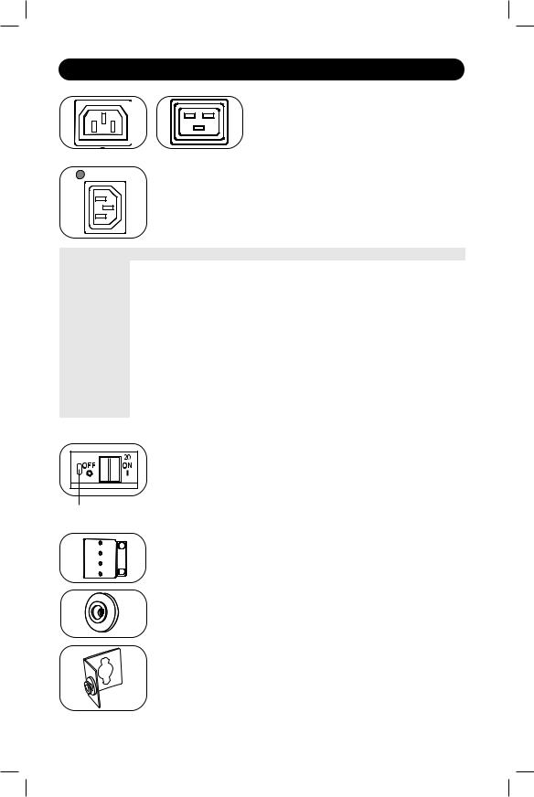
Outlets: During normal operation, the outlets distribute AC power to connected equipment.
C13 |
C19 |
Outlet Status LED: Once the unit is powered on, each outlet individually ramps up and each Outlet Status LED will illuminate when the associated outlet is ready to distribute live AC power.
|
|
|
|
|
|
|
|
|
|
|
|
|
|
|
|
|
|
|
|
|
|
|
|
|
|
|
|
|
|
|
|
|
|
|
|
LED Configuration |
LED Color |
Outlet Status |
Description |
|||||
|
|
|
|
|
Off |
Off |
Outlet power is absent |
|
|
|
|
|
|
Green |
On |
Circuit breaker is on – Outlet power is present |
|
|
|
|
|
|
Yellow |
On |
Outlet’s current has exceeded 80% of the outlet current |
|
Standard1 |
rating – Outlet power is present |
|||||||
|
|
|||||||
|
|
|
|
|
Red |
Off |
Outlet’s voltage is below the Low Voltage threshold – Outlet |
|
|
|
|
|
|
power is absent |
|||
|
|
|
|
|
|
|
||
|
|
|
|
|
Red Flashing |
Off |
Circuit breaker has tripped – Outlet power is absent |
|
|
|
|
|
|
Off |
Off |
Outlet power is absent |
|
|
|
|
|
|
Red |
On |
Circuit breaker is on – Outlet power is present |
|
Alternate |
Red Flashing |
On |
Outlet’s current has exceeded 80% of the outlet current |
|||||
rating – Outlet power is present |
||||||||
|
|
|
|
|
|
|
||
|
|
|
|
|
Green |
Off |
Outlet is disabled – Outlet power is absent |
|
|
|
|
|
|
Green Flashing |
Off |
Circuit breaker has tripped – Outlet power is absent |
|
1 This is the default configuration.
Circuit Breaker (Select Models): There are 3 Load Banks, each
protected by a circuit breaker. If the connected equipment load exceeds the Maximum Load Rating for those banks of the PDU, the circuit breaker will trip. Disconnect excess load and reset the breaker.
Note: Each breaker comes equipped with a push-to-reset guard to prevent Push-to-Reset Guard accidental breaker tripping. To turn off the breaker, insert a flathead screwdriver into
the reset slot.
Mounting Brackets: Use these brackets as an alternate PDU mounting method.
Mounting Buttons: Located on the back side of the PDU, the preinstalled buttons are used for toolless mounting.
Note: Four additional mounting buttons are included for alternate rack styles.
PDUMVROTATEBRKT Mounting Accessory: Use these L-shaped brackets to mount the PDU with its outlets facing the rear of the rack.
14

Features
C14 Plug-Lock Inserts (Optional): Use the included C14 plug-lock inserts to secure plugs to C13 receptacles. Attach the sleeve to the plug making sure the pull tabs remain outside the plug and that the fit is secure. To unplug equipment properly, use the pull tabs to remove the plug and insert from the receptacle.
C20 Plug-Lock Inserts (Optional): Use the included C20 plug-lock inserts to secure plugs to C19 receptacles. Attach the sleeve to the plug making sure the pull tabs remain outside the plug and that the fit is secure. To unplug equipment properly, use the pull tabs to remove the plug and insert from the receptacle.
Ground Screw: Use this to connect any equipment that requires a chassis ground.
Network Interface
A
A3
A2
A1
C |
B |
AUSB Ports: The two USB-A ports A1 and A2 connect to one of four different Tripp Lite EnviroSense2 (E2) environmental sensors* for remote temperature or
temperature/humidity monitoring (up to three E2 sensors can be daisy-chained). The USB-B port A3 is used for initial network interface configuration and direct console access from a laptop**.
*USB-A ports are designed for use with E2 modules only. Do not connect other USB devices to these ports.
**Only 2 of 3 USB ports can be used simultaneously. For example: 2 USB-A ( A1 and A2 ), or 1 USB-B and the lower USB-A port ( A3 and A1 ); the upper USB-A port A2 cannot connect with the USB-B port A3 .
C1
<![endif]>ACTIVITY
C2 LINK
D
<![endif]>RESET
<![endif]>CONFIG
BRJ45 Configuration Port: This port can also be used to configure the network interface and command line access from a laptop.
CEthernet Port: Use this RJ45 jack to connect the PDU to the network with a standard Ethernet patch cable. The behavior of the Activity LED C1 and Link LED C2 is shown in the table below. This port is not compatible with PoE (Power Over Ethernet) applications.
LED Function |
LED Color |
Off |
On |
Flashing |
Activity |
Green |
No Activity |
— |
Activity |
Link |
Yellow |
No Link |
Link (Any Speed) |
— |
DSNMP Reset Button: The reset button is recessed. Use a paper clip or other suitable object to press the reset button for 3 seconds to reboot the PDU’s network interface. Rebooting the network interface will not erase network settings or interrupt AC power. Press and hold the reset button for 20 seconds to restore the PDU’s network interface to its factory default settings. Restoring to the factory default will erase all previously saved data—including network settings—without interrupting AC power.
15

Configuration and Operation
Remote Monitoring and Control
The PDU can be monitored and controlled remotely via Web browser, telnet and SNMP-based Network Management Systems. For more information about configuration and operation of the PDU via the PowerAlert Device Manger, refer to the LX Platform User’s Guide, which can be found by going to tripplite.com/support and typing LX Platform in the search field.
Service
Your Tripp Lite product is covered by the warranty described in this manual. A variety of Extended Warranty and On-Site Service Programs are also available from Tripp Lite. For more information on service, visit tripplite.com/support. Before returning your product for service, follow these steps:
1.Review the installation and operation procedures in this manual to ensure that the service problem does not originate from a misreading of the instructions.
2.If the problem continues, do not contact or return the product to the dealer. Instead, visit tripplite.com/support.
3.If the problem requires service, visit tripplite.com/support and click the Product Returns link. From here you can request a Returned Material Authorization (RMA) number, which is required for service. This simple on-line form will ask for your unit’s model and serial numbers, along with other general purchaser information. The RMA number, along with shipping instructions will be emailed to you. Any damages (direct, indirect, special or consequential) to the product incurred during shipment to Tripp Lite or an authorized
Tripp Lite service center is not covered under warranty. Products shipped to Tripp Lite or an authorized Tripp Lite service center must have transportation charges prepaid. Mark the RMA number on the outside of the package. If the product is within its warranty period, enclose
a copy of your sales receipt. Return the product for service using an insured carrier to the address given to you when you request the RMA.
16

Warranty and Product Registration
2- YEAR LIMITED WARRANTY
Seller warrants this product, if used in accordance with all applicable instructions, to be free from original defects in material and workmanship for a period of 2 years from the date of initial purchase. If the product should prove defective in material or workmanship within that period, Seller will repair or replace the product, in its sole discretion. Service under this Warranty can only be obtained by your delivering or shipping the product (with all shipping or delivery charges prepaid) to: Tripp Lite, 1111 W. 35th Street, Chicago, IL 60609 USA. Seller will pay return shipping charges. Visit tripplite.com/support before sending any equipment back for repair.
THIS WARRANTY DOES NOT APPLY TO NORMAL WEAR OR TO DAMAGE RESULTING FROM ACCIDENT, MISUSE, ABUSE OR NEGLECT. SELLER MAKES NO EXPRESS WARRANTIES OTHER THAN THE WARRANTY EXPRESSLY SET FORTH HEREIN. EXCEPT TO THE EXTENT PROHIBITED BY APPLICABLE LAW, ALL IMPLIED WARRANTIES, INCLUDING ALL WARRANTIES OF MERCHANTABILITY OR FITNESS, ARE LIMITED IN DURATION TO THE WARRANTY PERIOD SET FORTH ABOVE; AND THIS WARRANTY EXPRESSLY EXCLUDES ALL INCIDENTAL AND CONSEQUENTIAL DAMAGES. (Some states do not allow limitations on how long an implied warranty lasts, and some states do not allow the exclusion or limitation of incidental or consequential damages, so the above limitations or exclusions may not apply to you. This Warranty gives you specific legal rights, and you may have other rights which vary from jurisdiction to jurisdiction).
WARNING: The individual user should take care to determine prior to use whether this device is suitable, adequate or safe for the use intended. Since individual applications are subject to great variation, the manufacturer makes no representation or warranty as to the suitability or fitness of these devices for any specific application.
PRODUCT REGISTRATION
Visit tripplite.com/warranty today to register your new Tripp Lite product.You’ll be automatically entered into a drawing for a chance to win a FREE Tripp Lite product!*
* No purchase necessary. Void where prohibited. Some restrictions apply. See website for details.
FCC Notice, Class A
This device complies with part 15 of the FCC Rules. Operation is subject to the following two conditions:
(1) This device may not cause harmful interference, and (2) this device must accept any interference received, including interference that may cause undesired operation.
Note: This equipment has been tested and found to comply with the limits for a Class A digital device, pursuant to part 15 of the FCC Rules. These limits are designed to provide reasonable protection against harmful interference when the equipment is operated in a commercial environment. This equipment generates, uses, and can radiate radio frequency energy and, if not installed and used in accordance with the instruction manual, may cause harmful interference to radio communications. Operation of this equipment in a residential area is likely to cause harmful interference in which case the user will be required to correct the interference at his own expense. The user must use shielded cables and connectors with this equipment. Any changes or modifications to this equipment not expressly approved by Tripp Lite could void the user’s authority to operate this equipment.
Regulatory Compliance Identification Numbers
For the purpose of regulatory compliance certifications and identification, your Tripp Lite product has been assigned a unique series number. The series number can be found on the product nameplate label, along with all required approval markings and information. When requesting compliance information for this product, always refer to the series number. The series number should not be confused with the marketing name or model number of the product.
WEEE Compliance Information for Tripp Lite Customers and Recyclers (European Union)
Under the Waste Electrical and Electronic Equipment (WEEE) Directive and implementing regulations, when
customers buy new electrical and electronic equipment from Tripp Lite they are entitled to:
• Send old equipment for recycling on a one-for-one, like-for-like basis (this varies depending on the country)
• Send the new equipment back for recycling when this ultimately becomes waste
Tripp Lite has a policy of continuous improvement. Specifications are subject to change without notice.
1111 W. 35th Street, Chicago, IL 60609 USA • tripplite.com/support
17 |
20-02-012 93-349E_RevG |

Manual del Propietario
Unidades de Distribución de Energía Trifásicas Controlables de 0U
(Mediciones de Fase, Banco y Tomacorrientes*)
MODELOS |
NO. DE |
MONITOREABLES DE 208V |
SERIE |
PDU3EVN3L2130 |
AG-00B9 |
PDU3EVN10L2130 |
AG-00B9 |
PDU3EVN3L2120 |
AG-00B8 |
PDU3EVN6L2120 |
AG-00B8 |
PDU3EVN10L2120 |
AG-00B8 |
PDU3EVN6L2130 |
AG-00B9 |
MODELOS |
NO. DE |
CONTROLABLES DE 208V |
SERIE |
PDU3EVSR6G60A |
AG-0063 |
PDU3EVSR6H50A |
AG-0065 |
MODELOS |
NO. DE |
MONITOREABLES DE 200V ~ 240V |
SERIE |
PDU3EVN6G30B |
AG-00BA |
PDU3EVN10G30B |
AG-00BA |
PDU3EVN3G60B |
AG-00BA |
PDU3EVN6G60B |
AG-00BA |
PDU3EVN10G60B |
AG-00BA |
PDU3EVN3H50B |
AG-00BA |
PDU3EVN6H50B |
AG-00BA |
PDU3EVN6H50BA |
AG-00BA |
PDU3EVN10H50B |
AG-00BA |
PDU3EVN3L1520 |
AG-00BA |
PDU3EVN6L1520 |
AG-00BA |
PDU3EVN10L1520 |
AG-00BA |
PDU3EVN3L1530B |
AG-00BA |
PDU3EVN6L1530B |
AG-00BA |
PDU3EVN10L1530B |
AG-00BA |
PDU3EVN3L2130B |
AG-00BA |
PDU3EVN6L2130B |
AG-00BA |
PDU3EVN10L2130B |
AG-00BA |
PDU3EVN2 |
AG-00BA |
PDU3EVN6G60C |
AG-00BB |
MODELOS |
NO. DE |
CONTROLABLES DE 200V ~ 240V |
SERIE |
PDU3EVSR6H50 |
AG-00BA |
PDU3EVSR10H50 |
AG-00BA |
PDU3EVSR6L1530 |
AG-00BA |
PDU3EVSR10L1530 |
AG-00BA |
PDU3EVSR6L2130 |
AG-00BA |
PDU3EVSR6G60 |
AG-00BA |
PDU3EVSR10L2130 |
AG-00BA |
PDU3EVS6H50 |
AG-00BA |
PDU3EVS6L2130 |
AG-00BA |
PDU3EVS6L2120 |
AG-00BC |
PDU3EVSR6L2120 |
AG-00BC |
PDU3EVSR6L1520 |
AG-00BC |
MODELOS |
NO. DE |
MONITOREABLES DE 380V ~ 415V |
SERIE |
PDU3XEVN6G20 |
AG-00BD |
MODELOS |
NO. DE |
CONTROLABLES DE 380V ~ 415V |
SERIE |
PDU3XEVSR6G20 |
AG-00BD |
PDU3XEVSR6G30A |
AG-0096 |
PDU3XEVSR6G30B |
AG-0096 |
PDU3XEVSR6G32A |
AG-0080 |
PDU3XEVSR6G32B |
AG-0080 |
PDU3XEVSR6G60A |
AG-0093 |
PDU3XEVSR6G60B |
AG-0093 |
PDU3XEVSR6G63A |
AG-0094 |
PDU3XEVSR6G63B |
AG-0094 |
PDU3XEVSR6L230B |
AG-0056 |
PDU3XEVSR6L2230 |
AG-0056 |
PDU3XEVSRHWA |
AG-0057 |
PDU3XEVSRHWB |
AG-0057 |
*Varía por producto. |
|
English 1 • Français 35 • Русский 52
1111 W. 35th Street, Chicago, IL 60609 EE. UU. • tripplite.com/support
Copyright © 2020 Tripp Lite. Todos los derechos reservados.
18

Instrucciones de Seguridad Importantes
CONSERVE ESTAS INSTRUCCIONES
Este manual contiene instrucciones y advertencias que deben seguirse durante la instalación, operación y almacenamiento de este producto.
La omisión en la observancia de estas instrucciones y advertencias puede afectar la garantía del producto.
•El PDU proporciona la conveniencia de múltiples tomacorrientes, pero NO proporciona protección contra sobretensiones o ruido en la línea para los equipos conectados.
•El PDU está diseñada solo para uso en interiores en un entorno controlado lejos de humedad excesiva, temperaturas extremas, contaminantes conductivos, polvo o luz del sol directa.
•Mantiene la temperatura ambiente interior entre 0 ºC y 50 ºC [32 ºF y 122 ºF]
•El PDU debe ser instalado solamente por un técnico calificado.
•No intente instalar el PDU en una superficie inestable o no segura.
•Instale conforme a los estándares del Código Eléctrico Nacional. Asegúrese de usar la protección adecuada contra sobre-corriente para la instalación, de conformidad con la especificación de la clavija y del equipo.
•Conecte el PDU a un tomacorrientes que esté de acuerdo a los reglamentos locales de construcción y que esté correctamente protegido contra corrientes excesivas, cortocircuitos y fallas de conexión a tierra.
•Los tomacorrientes eléctricos que alimentan al equipo deben instalarse cerca del equipo y ser fácilmente accesibles.
•No conecte el PDU a un toma corriente que no esté a tierra o cables de extensión o adaptadores que eliminen la conexión a tierra.
•Asegúrese de proporcionar un dispositivo local de desconexión, que sea fácilmente accesible, en cualquier modelo que esté instalado permanentemente sin una clavija.
•Nunca intente instalar equipos eléctricos durante una tormenta eléctrica.
•Cada equipo conectado al PDU no debe consumir en forma individual más corriente que la de la especificación de cada tomacorrientes individual del PDU.
•La carga total conectada al PDU no debe exceder la capacidad de carga máxima del PDU.
•No intente modificar el PDU, las clavijas de entrada o los cables de alimentación.
•No perfore ni intente abrir ninguna parte del gabinete del PDU. No tiene partes a las que el usuario pueda dar servicio.
•No intente usar el PDU si se daña cualquier parte.
•No se recomienda el uso de este equipo en aplicaciones de soporte de vida en donde la falla de este equipo pueda razonablemente causar la falla del equipo de soporte de vida o afectar significativamente su seguridad o efectividad.
19

Instalación
Instalación del PDU
Nota: Las ilustraciones pueden diferir un poco de su modelo de PDU. Sin impostar la configuración, antes de la instalación, el usuario debe determinar la adecuación de los accesorios y procedimientos. El PDU y los accesorios incluidos están diseñados para tipos comunes de racks y gabinetes y pueden no ser apropiados para todas las aplicaciones. Las configuraciones de instalación exactas pueden variar. Los tornillos para fijar los soportes de instalación al PDU están incluidos. Use solamente los tornillos suministrados por el fabricante o su equivalente exacto.
Nota: Para instalación sin herramienta, los botones de instalación vienen pre-instalados en el PDU.
1-1
1-2
Para fijar los soportes de instalación en el PDU, retire los botones de instalación.
Con los tornillos incluidos, fije los soportes de instalación al PDU.
1-1 |
1-2 |
1-3
1-4
1-5
Fije el PDU a un riel vertical en su rack |
|
||
o gabinete. (Use los accesorios de |
|
||
Instalación que vinieron con su rack |
|
||
o gabinete para fijar los soportes de |
1-3 |
||
instalación al riel). |
|
||
Para reinstalar los botones de |
|
|
|
instalación para instalación sin |
|
|
|
herramientas, retire los soportes de |
|
||
instalación y coloque los botones de |
1-4 |
||
instalación en el PDU. Coloque el PDU |
|||
|
|||
como desee en el gabinete, alinee los |
|
||
botones con las ranuras de instalación |
|
||
del rack y deslice el PDU a su posición. |
|
||
Nota: Asegúrese de insertar los 2 botones en el |
|
||
orificio superior en cada extremo del PDU o en |
|
||
el orificio inferior en cada extremo del PDU. |
|
||
Para instalar el PDU con sus |
|
|
|
tomacorrientes viendo hacia la parte |
|
||
posterior del rack, use el accesorio |
|
||
PDUMVROTATEBRKT incluido. Primero, |
|
||
instale el botón de instalación |
A en |
|
|
el soporte con perfil en V B usando |
|
||
el tornillo y la arandela incluidos. |
|
||
Entonces, use la ranura de instalación |
|
||
por botón para fijar el soporte al PDU |
|
||
y el botón para fijar el PDU al rack. El |
|
||
soporte reposiciona efectivamente los |
|
||
soportes de instalación permitiendo que |
|
||
los tomacorrientes del PDU vean hacia |
|
||
la parte posterior del rack. |
|
|
|
B
A
1-5
20
Instalación
Conexión del PDU
2-1 Cada modelo está equipado con 1 de 8 clavijas de alimentación diferentes.
L15-20P |
L15-30P |
|
L21-20P |
L21-30P |
L22-30P |
Hubbell CS8365C |
||
|
|
|
|
|
|
|
|
|
|
|
|
|
|
|
|
|
|
IEC 309 |
IEC 309 |
|
|
IEC 309 |
|
IEC 309 |
|
IEC 309 |
||
30A Azul |
60A Azul |
|
|
32A Rojo |
63A Rojo |
|
60A Azul |
|||
(3P + T) |
(3P + T) |
|
(3P + N + T) |
(3P + N + T) |
(3P + N + T) |
|||||
|
|
|
|
|
|
|
|
|
|
|
|
|
|
Amperes Máx. |
|
|
|
|
|
|
|
|
|
|
de Entrada |
|
Rango |
|
Rango |
|
|
|
|
|
|
(Limitados |
|
del |
|
del |
|
|
|
Modelos |
|
|
por Cable y |
|
Voltaje |
|
Voltaje |
|
|
|
Monitoreables de |
Clavija de |
|
Clavija de |
|
de |
|
de |
|
Longitud |
|
208V |
Entrada |
|
Alimentación) |
|
Entrada |
|
Salida |
Breakers |
de Cable |
Tomacorrientes |
|
|
|
|
|
|
|
|
3 x Doble Polo, 20A |
|
36 x C13; |
PDU3EVN3L2130 |
L21-30P |
|
24A |
|
208V |
|
208V |
91 cm |
6 x C19; |
|
|
|
|
Especificados por Ramal |
|||||||
|
|
|
|
|
|
|
|
|
3 x 5-15/20R |
|
|
|
|
|
|
|
|
|
|
|
|
|
|
|
|
|
|
|
|
3 x Doble Polo, 20A |
|
36 x C13; |
PDU3EVN10L2130 |
L21-30P |
|
24A |
|
208V |
|
208V |
3.05 m |
6 x C19; |
|
|
|
|
Especificados por Ramal |
|||||||
|
|
|
|
|
|
|
|
|
|
3 x 5-15/20R |
PDU3EVN3L2120 |
L21-20P |
|
16A |
|
208V |
|
208V |
N/A |
91 cm |
42 X C13; |
|
|
|
6 X C19 |
|||||||
|
|
|
|
|
|
|
|
|
|
|
|
|
|
|
|
|
|
|
|
|
|
PDU3EVN6L2120 |
L21-20P |
|
16A |
|
208V |
|
208V |
N/A |
1.83 m |
42 X C13; |
|
|
|
6 X C19 |
|||||||
|
|
|
|
|
|
|
|
|
|
|
|
|
|
|
|
|
|
|
|
|
|
PDU3EVN10L2120 |
L21-20P |
|
16A |
|
208V |
|
208V |
N/A |
3 m |
42 X C13; |
|
|
|
6 X C19 |
|||||||
|
|
|
|
|
|
|
|
|
|
|
|
|
|
|
|
|
|
|
|
|
|
|
|
|
|
|
|
|
|
3 x Doble Polo, 20A |
|
36 x C13; |
PDU3EVN6L2130 |
L21-30P |
|
24A |
|
208V |
|
208V |
1.83 m |
6 x C19; |
|
|
|
|
Especificados por Ramal |
|||||||
|
|
|
|
|
|
|
|
|
|
3 x 5-15/20R |
|
|
|
Amperes Máx. |
|
|
|
|
|
|
|
|
|
|
de Entrada |
|
Rango |
|
Rango |
|
|
|
|
|
|
(Limitados |
|
del |
|
del |
|
|
|
Modelos |
|
|
por Cable y |
|
Voltaje |
|
Voltaje |
|
|
|
Controlables de |
Clavija de |
|
Clavija de |
|
de |
|
de |
|
Longitud |
|
208V |
Entrada |
|
Alimentación) |
|
Entrada |
|
Salida |
Breakers |
de Cable |
Tomacorrientes |
|
|
|
|
|
|
|
|
|
|
|
|
|
|
|
|
|
|
|
6 x Bajo Perfil |
|
|
|
|
|
|
|
|
|
|
con Cerradura de |
|
|
PDU3EVSR6G60A |
IEC 309 60A Azul |
|
45A |
|
208V |
|
208V |
Seguridad, Doble |
1.83 m |
6 x C13; |
(3P + T); IP44 |
|
|
|
Polo, Magnético, |
12 x C19 |
|||||
|
|
|
|
|
|
|
|
|||
|
|
|
|
|
|
|
|
Especificado por |
|
|
|
|
|
|
|
|
|
|
Ramal |
|
|
|
|
|
|
|
|
|
|
6 x Bajo Perfil |
|
|
|
IEC 309 60A Azul |
|
|
|
|
|
|
con Cerradura de |
|
|
PDU3EVSR6G60A |
(3P + N + T), |
|
45A |
|
208V |
|
208V |
Seguridad, Doble |
1.83 m |
6 x C13; |
IP67 |
|
|
|
Polo, Magnético, |
12 x C19 |
|||||
|
|
|
|
|
|
|
|
|||
|
N No Usado |
|
|
|
|
|
|
Especificado por |
|
|
|
|
|
|
|
|
|
|
Ramal |
|
|
|
|
|
|
|
|
|
|
6 x Bajo Perfil |
|
|
|
|
|
|
|
|
|
|
con Cerradura de |
|
|
PDU3EVSR6H50A |
Hubbell CS8365C |
|
40A |
|
208V |
|
208V |
Seguridad, Doble |
1.83 m |
6 x C13; |
|
|
|
Polo, Magnético, |
12 x C19 |
||||||
|
|
|
|
|
|
|
|
|
||
|
|
|
|
|
|
|
|
Especificado por |
|
|
|
|
|
|
|
|
|
|
Ramal |
|
|
|
|
|
|
|
|
|
|
|
|
|
21
 Loading...