


Tripp Lite SU50K3, SU503PM, SU803PM, SU80K3, SU503INTPM User Manual
...WARRANTYtoday |
|
|
|
chance |
— |
Owner's Manual |
|||||
|
|
|
|
|
|||||||
|
|
|
|
|
|
||||||
REGISTRATION: |
|
product |
|
|
|
|
|||||
|
|
|
for |
a |
|
|
|
|
|
||
|
|
|
.com/warranty |
|
|
|
|||||
|
|
Tripp |
Lite |
|
|
|
|
|
|||
|
online |
|
|
|
|
|
|
|
|
||
|
|
|
|
|
|
|
|
|
|
|
|
|
FREE |
|
|
|
|
|
|
|
|
|
|
|
a .tripplite |
|
|
|
|
|
|
|
|
||
register |
|
|
|
|
|
SmartOnline |
™ |
3-Phase (50kVA & Above) |
|||
|
win www |
|
|
|
|
|
|||||
|
|
|
|
|
|
|
|
|
|
|
|
to |
|
|
|
|
|
|
|
|
|
|
|
Intelligent True On-Line UPS Systems
Input/Output:
3Ø, 4 Wire (plus ground), wye
•SU50K3/3PM & SU80K3/3PM Models: ................277/480V AC
•SU50K3/3INTPM & SU80K3/3INTPM Models:......220/380, 230/400 or 240/415V AC (user-selectable)*
 **
**
* See "Parameter Setting" Sub-Menu on page 17 to set the inverter output voltage. ** CE certification applies to SU50K3/3INTPM and SU80K3/3INTPM only
There are two separate UPS system modules: a power module and a 348V DC battery module. The power module is described in this manual. The 348V DC battery module is described in its owner's manual, printed separately. The model numbers listed in this manual are for the power module only.
Important Safety Warnings |
2 |
|
|
|
|
Power Module Features |
4 |
|
|
|
|
Installation |
5 |
|
|
|
|
Electrical Connection |
6 |
|
|
|
|
Single UPS Operation |
8 |
|
|
|
|
Multiple UPS Operation (Parallel) |
11 |
|
|
|
|
LCD Display Navigation |
16 |
|
|
|
|
Communications |
20 |
|
|
|
|
Service |
23 |
|
|
|
|
Warranty & Warranty Registration |
23 |
|
|
1111 W. 35th Street • Chicago, IL 60609 USA
(773) 869-1234 • www.tripplite.com
Copyright ©2005 Tripp Lite. All rights reserved. SmartOnline™ is a trademark of Tripp Lite.
The policy of Tripp Lite is one of continuous improvement. Specifications and operating procedures are subject to change without notice. This product designed and engineered in the USA.

Important Safety Warnings
SAVE THESE INSTRUCTIONS. This manual contains important instructions and warnings that should be followed during the installation and maintenance of all Tripp Lite SmartOnline 3-Phase UPS Systems (50kVA and above) and their batteries. All UPS connection and maintenance must be performed by qualified service personnel. The UPS should only be installed in accordance with the requirements of IEC 60364-4-48. (The UPS complies with EN 50091-1-1, EN 50091-2, IEC 61000-4-2 Level 4, IEC 61000-4-3 Level 3, IEC 61000-4-4 Level 4, IEC 61000-4-5 Level 4 and IEC 61000-4-6.)
Service personnel should familiarize themselves with symbols marked on the UPS:
This symbol indicates a protective grounding terminal (a terminal which must be connected to earth ground prior to making any other connection to the equipment).
This symbol indicates a terminal to which or from which a direct current or voltage may be applied or supplied.
This symbol indicates the word “phase”.
UPS Location Warnings
•Install your UPS indoors, away from heat, direct sunlight, dust, and excess moisture or other conductive contaminants.
•Install your UPS away from flammable liquids and gases. Do not let the unit come in contact with water or other liquids.
•Install your UPS in a structurally sound area. Your UPS is extremely heavy. Flooring must be able to support the weight of all UPS modules. Take care when moving and lifting the unit.
•Only operate your UPS at indoor temperatures between 32° F and 104° F (between 0° C and 40° C) with humidity within a range of 0 to 95% (non-condensing). For best results, keep indoor temperatures between 62° F and 84° F (between 17° C and 29° C).
•Leave adequate space around all sides of the UPS for proper ventilation: at least 40 inches (100 cm) from front panel and 20 inches (50 cm) from top, rear and side panels. Do not cover ventilation openings on the unit.
•Do not install the UPS near magnetic storage media, as this may result in data corruption.
UPS Connection Warnings
•The power supply for this unit must be three-phase rated in accordance with the equipment nameplate. It also must be suitably grounded according to all applicable local electrical wiring regulations.
•The UPS must be isolated prior to any connection or maintenance. A readily-accessible disconnect device must be incorporated into the wiring following all local electrical codes. The disconnect device must be four-pole and must be able to disconnect all line conductors and the neutral conductor.
•Due to high leakage current, a ground connection is essential.
Equipment Connection Warnings
•Do not use Tripp Lite UPS Systems in life support applications in which a malfunction or failure of a Tripp Lite UPS System could cause failure or significantly alter the performance of a life support device.
•The UPS is designed to power computer equipment. Do not use the UPS with purely inductive or capacitive loads.
•The UPS System includes its own energy source (external battery). The output terminals may be live even when the UPS is not connected to an AC supply.
Battery Warnings
•Your UPS does not require routine maintenance. Do not open your UPS for any reason. There are no user-serviceable parts inside.
•Risk of electrocution is possible when battery module is connected to the power module. Qualified service personnel must disconnect the batteries prior to maintenance.
•Because the batteries present a risk of electrical shock and burn from high short-circuit current, batteries should be changed only by trained service personnel observing proper precautions. Consult your battery module manual before proceeding. Remove watches, rings, and other metal objects. Use tools with insulated handles. Wear rubber gloves and boots. Do not lay tools or metal parts on top of the batteries. Do not short or bridge the battery terminals with any object. Disconnect the charging source prior to connecting or disconnecting battery terminals. Determine if the batteries are inadvertently grounded. If inadvertently grounded, remove the source of the ground. Contact with any part of a grounded battery can result in electrical shock. The likelihood of such shock will be reduced if such grounds are removed during installation and maintenance.
•Do not dispose of the batteries in a fire. The UPS batteries are recyclable. Refer to local codes for disposal requirements, or in the USA only, refer to these sources for recycling information: 1-800-SAV-LEAD (1-800-728-5323), 1-800-8-BATTERY (1-800-8-228-8379), or www.rbrc.com.
2

Important Safety Warnings (continued)
•Connect only Tripp Lite battery modules to your UPS's external battery hardware terminals.
•Do not operate your UPS without batteries.
•Fuses should be replaced only by factory authorized personnel. Blown fuses should be replaced only with fuses of the same number and type.
•Potentially lethal voltages exist within this unit as long as the battery supply is connected. Service and repair should be done only by trained personnel. During any service work, the UPS should be turned off or put into manual bypass and fuses removed from all connected battery modules.
•Do not connect or disconnect the battery modules while the UPS is operating from the battery supply or when the unit is not in bypass mode.
Regulatory Compliance Identification Numbers
For the purpose of regulatory compliance certifications and identification, your Tripp Lite product has been assigned a unique series number. The series number can be found on the product nameplate label, along with all required approval markings and information. When requesting compliance information for this product, always refer to the series number. The series number should not be confused with the marking name or model number of the product.
3

Power Module Features
There are two separate UPS system modules: a power module and a 348V DC battery module. Familiarize yourself with the location and function of the features on each module before installing and operating your UPS system. The power module is described below. The 348V DC battery module is described in its owner's manual, printed separately.
Buttons
50kVA - 80kVA Power Module Front Panel with Door Open
See LED |
|
5 |
|
|
|
Panel |
|
|
4 |
|
|
1 |
2 |
3 |
1. “ON” Button: This button, when used with the “
 ” Button, turns the UPS's inverter on. To turn the UPS's inverter on, simultaneously press the “ON” Button and the “
 ” Button and hold for 3 seconds before releasing.
2 This button, when used with the “ ” Button, turns the UPS's
2. “OFF” Button:
inverter off. To turn the UPS's inverter off, simultaneously press the “OFF” Button and the “
 ” Button and hold for 3 seconds before releasing.
3. “
 ”, “
”, “ ” and “
 ” Buttons: These buttons control the LCD Display and setting parameters.
4. “EMERGENCY POWER OFF” Button: This button turns off the UPS's rectifier, inverter and output in an emergency. After pressing the button, it will remain down until reset. To reset the UPS system and restore output, press the “Emergency Power OFF” Button until it pops back up.
LCD Display
5. LCD Display: This backlit dot matrix display indicates a wide range of UPS operating conditions and diagnostic data. It will illuminate after you have properly completed installation and start-up.
LED Panel
6. “MAINTENANCE BYPASS” LED: This red light will illuminate when the UPS is providing filtered mains power without engaging its converter or inverter. Connected equipment will not receive battery power in the event of a blackout.
7. “RESERVE POWER” LED: This green light will illuminate to indicate the presence of a reserve power breaker and reserve power source connected to the UPS.
8. “RECTIFIER” LED: This green light will illuminate to indicate the UPS rectifier is operating.
99. “BATTERY” LED: This orange light will illuminate when the UPS is discharging the battery to provide connected equipment with AC power.
10. “INVERTER” LED: This green light will illuminate constantly to indicate the UPS's DC/AC inverter is activated.
20
14 |
15 |
16 |
17 |
18 |
19 |
|
|
See Communication
Interface
11. “RESERVE POWER STATIC SWITCH” LED: This green light will illuminate when the UPS is powering connected equipment through a reserve power source connected to the UPS.
12. “INVERTER MC” LED: This green light will illuminate to indicate connected equipment is supplied with power through the UPS's inverter.
13. “AC OUTPUT” LED: This green light will illuminate constantly to indicate your UPS is supplying AC power to connected equipment.
6
11
7 
13
Breakers, Switches & Fuses |
8 |
|
|
|
|
|
|
|
|
|
|||
|
Rectifier Input Breaker: This breaker controls input power to the UPS |
|
|
|
|
|
14. |
9 |
|
|
|
|
|
|
|
|
|
|||
|
during normal operation. |
|
|
|
|
|
|
|
|
|
|
|
|
|
Reserve Input Breaker: This breaker controls input power to the UPS |
|
|
|
|
|
15. |
10 |
LED Panel |
||||
|
when operating from reserve power. |
|
|
|
|
|
12
16. Manual Bypass Breaker: This breaker controls input power to the UPS during bypass operation.
17. UPS Output Breaker: This breaker controls UPS output to connected equipment.
189. Fan Fuse: This fuse disconnects “N” between main “N” and inner circuit of “N”. It also protects the fan's circuit.
2019. Power Fuse: This fuse disconnects the battery and auxiliary power circuits during maintenance. It also protects the auxiliary power circuit.
4
Power Module Features (continued)
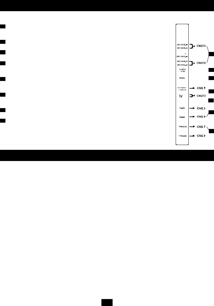
Communication Interface
Communication Interface
2120. Accessory Slot (see previous page for location): Remove the small cover panel and use optional accessories. Contact Tripp Lite Customer Support for more information and a list of available SNMP, network management and connectivity products.
21 #1 (UPS Normal); #2 (Load On Reserve); #3 (Load On Battery); #4 (Battery Low Voltage);
22. Dry Contacts:
#5 (Reserve Abnormal); #6 (Battery Test Fail). See “Communications” for details.
22 This modular jack allows remote emergency shutdown.
23. Remote “Emergency Power OFF” (EPO) Connector:
See “Communications” for details.
2423. “Smart” RS-232 Interface Port: This female DB9 port connects your UPS to a workstation or server. It uses RS-232 communications to report UPS and power conditions. It is used with Tripp Lite software and cabling. See “Communications” for details.
245) Ethernet Port & Ethernet Power: The Ethernet Port is an RS-232 port that accepts an optional RS-232/RJ45 Ethernet Adapter (sold separately). The Ethernet Power connection provides 12VDC power to the optional adapter. See “Communications” for details.
256) Generator Contact: This port connects to an auxiliary power generator. When the generator is operating to support the equipment load, the UPS System will automatically reduce its charge current by 50% in order to prevent overloading of the generator. See “Communications” for details.
267) RS-485 Ports: These ports allow multiple UPS power modules to be connected in a parallel configuration. See “Communications” for details.
278) UPS Parallel Communication Ports: These ports allow multiple UPS power modules to communicate while in a parallel configuration. See “Communications” for details.


 21
21


 22
22


 23
23
 24
24


 25
25
 26
26
 27
27
Installation
Follow all warnings listed in the Safety section prior to installation. The following checklist provides a general guide rather than a complete outline of procedures.
Installation Checklist
The floor area where the UPS will be installed has enough supporting strength. See “Floor Weight Loading Table” on page 6.
The entrances and hallways to the facility provide enough room for UPS transportation.
The room where the UPS will be installed has enough clearance around the UPS modules to allow adequate ventilation and access for operation and maintenance.
The facility's air conditioning can maintain ideal temperature and humidity levels.
Noise abating devices are installed (if desired).
Electrical wiring is clearly marked (for polarity and phase) and checked for compliance with local electrical codes.
The input power source has been switched off prior to hardwire connection.
The room where the UPS will be installed includes floor, ceiling and walls made of flameproof materials. The room includes a fire extinguisher. The room is secure from access by unauthorized personnel.
All personnel are sufficiently trained for normal and emergency operations.
During installation, the UPS input neutral is solidly connected to the utility power neutral.
5

Installation (continued)
Floor Weight Loading Table
UPS Power Module
Model |
SU50K3/3PM |
SU80K3/3PM |
SU50K3/3INTPM |
SU80K3/3INTPM |
|
|
|
|
|
UPS System Capacity (kVA) |
50 |
80 |
50 |
80 |
|
|
|
|
|
Weight (lb) |
1276 |
1540 |
1012 |
1155 |
Weight (kg) |
580 |
700 |
460 |
525 |
|
|
|
|
|
Weight Loading (lb/in2) |
1716 |
1495 |
1361 |
1554 |
Weight Loading (kg/m2) |
1208 |
1054 |
958 |
1094 |
See Battery Module Owner's Manual or Contact Tripp Lite for Battery Module Weight Loading Information.
Electrical Connection
•Connection Checklist
•Recommended Cable Sizes
•Terminal Wiring Diagrams
•Parallel Wiring Diagrams
Follow all warnings listed in the Safety section prior to hardwire terminal connection. The following checklist provides a general guide rather than a complete outline of procedures.
Connection Checklist
Turn off input power prior to electrical connection.
Check the input, output and battery cables for proper amplitude, phase and polarization.
Connect ground wire(s) between UPS power module(s) and battery module(s).
If the input and output power of the UPS is a Y connection, then note that the Neutral wire and Ground wire are not connected within the UPS power module.
If the input power system has a floating voltage between Neutral and Ground, and if 0 volts is desired between Neutral and Ground within the UPS power module, Tripp Lite recommends the following: add a user-supplied isolation transformer to the input of the UPS, and connect the Neutral wire and Ground wire inside the UPS power module.
If installing multiple UPS modules in parallel, ensure input and output cables are the same length for each module.
Recommended Cable Sizes
UPS Power Module
Model |
SU50K3/3PM |
SU80K3/3PM |
SU50K3/3INTPM |
SU80K3/3INTPM |
UPS System Capacity (kVA) |
50 |
80 |
50 |
80 |
|
|
|
|
|
Input Circuit Breaker (A) |
100 |
150 |
125 |
200 |
Input Cable (AWG) |
2 |
1/0 |
1 |
3/0 |
Input Cable (mm2) |
22 |
50 |
35 |
70 |
|
|
|
|
|
Reserve Input Circuit Breaker (A) 75 |
125 |
100 |
150 |
|
Reserve Input Cable (AWG) |
6 |
2 |
4 |
1 |
Reserve Input Cable (mm2) |
10 |
25 |
16 |
35 |
|
|
|
|
|
Output Circuit Breaker (A) |
75 |
125 |
100 |
150 |
Output Cable (AWG) |
6 |
2 |
4 |
1 |
Output Cable (mm2) |
10 |
25 |
16 |
35 |
|
|
|
|
|
See Battery Module Owner's Manual or Contact Tripp Lite for Battery Module Cable Size Information.
Torque Specifications
50kVA Models: |
|
||
|
|
|
|
• 150A Terminal Blocks: 61 kgf/cm (4.4 ft/lb) |
|
||
• |
200A Terminal Blocks: 102 kgf/cm (7.5 ft/lb) |
|
|
80kVA Models: |
|
||
|
|
|
|
• |
200A Terminal Blocks: 102 kgf/cm (7.5 ft/lb) |
6 |
|
|
|
|
|

Electrical Connection (continued)
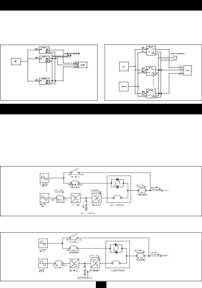
Terminal Wiring Diagrams
The following wiring diagrams are organized according to VA. Within each VA grouping, there is a “single loop” connection option (where only one input source is used) and a “double loop” connection option (where two input sources are used).
SU50K3/3PM & SU50K3/3INTPM Models |
|
|
|
|
|
|
|
|
|
|
|
|
|
|
|
|
|
|
||||||||
• Single Loop Connection (one input source used) |
|
|
|
|
|
• Double Loop Connection (two input sources used) |
||||||||||||||||||||
|
|
|
|
|
|
|
|
|
|
|
|
|
|
Note: cables labeled "1B", "2B" and "3B" from the Single Loop Connection diagram |
||||||||||||
|
|
|
|
|
|
|
|
|
|
|
|
|
|
are removed. |
||||||||||||
|
|
|
|
|
|
|
|
|
|
|
|
|
|
|
|
|
|
|
|
|
|
|
|
|
|
|
|
|
|
|
|
|
|
|
|
|
|
|
|
|
|
|
|
|
|
|
|
|
|
|
|
|
|
|
|
|
|
|
|
|
|
|
|
|
|
|
|
|
|
|
|
|
|
|
|
|
|
|
|
|
|
|
|
|
|
|
|
|
|
|
|
|
|
|
|
|
|
|
|
|
|
|
|
|
|
|
|
|
|
|
|
|
|
|
|
|
|
|
|
|
|
|
|
|
|
|
|
|
|
|
|
|
|
|
|
|
|
|
|
|
|
|
|
|
|
|
|
|
|
|
|
|
|
|
|
|
|
|
|
|
|
|
|
|
|
|
|
|
|
|
|
|
|
|
|
|
|
|
|
|
|
|
|
|
|
|
|
|
|
|
|
|
|
|
|
|
|
|
|
|
|
|
|
|
|
|
|
|
|
|
|
|
|
|
|
|
|
|
|
|
|
|
|
|
|
|
|
|
|
|
|
|
|
|
|
|
|
|
|
|
|
|
|
|
|
|
|
|
|
|
|
|
|
|
|
|
|
|
|
|
|
|
|
|
|
|
|
|
|
SU80K3/3INTPM Model Only
• Single Loop Connection (one input source used)
•Double Loop Connection (two input sources used)
Note: cables labeled "1C", "2C" and "3C" from the Single Loop Connection diagram are removed and connected to the terminal under the "Reserve Breaker".
SU80K3/3PM Model Only
• Single Loop Connection (one input source used)
•Double Loop Connection (two input sources used)
Note: cables labeled "1B", "2B" and "3B" from the Single Loop Connection diagram are removed.
7
Electrical Connection (continued)
Parallel Wiring Diagrams
In a parallel connection, up to eight UPS Systems are connected to a single load. A parallel connection provides fail-safe redundancy, assuring that the load is constantly supported even if one or more UPS Systems fail or are taken off-line for maintenance. Within a parallel architecture, there is a “single loop” connection option (where only one input source is used) and a “double loop” connection option (where two input sources are used). Note: in both connection options the total length of all cables (input, output and reserve) must be the same for each UPS Power Module to prevent load inequality.
All Models
• Single Loop Connection (one input source used)
• Double Loop Connection (two input sources used)
LOAD
Single UPS Operation
The diagrams and procedures in this section apply to a single UPS Power Module connected to a single equipment load. Note: all diagrams assume the presence of two separate AC sources supplying two separate inputs: a mains source supplying rectifier input and a reserve source supplying reserve input. If your application only allows a single mains AC source, this source will supply both rectifier and reserve input.
• Operational Modes |
• |
Shutdown Procedure |
• Start-Up Procedure |
• |
Manual Maintenance Bypass Procedure |
Operational Modes |
|
|
Normal Mode |
|
|
In this mode, the power module continuously converts AC input power into DC power (to recharge the batteries and supply the inverter). The inverter, in turn, transforms DC power into clean, stable AC output power for the connected equipment load.
Back-Up Mode
In this mode, utilityAC input power has failed. Since the UPS System operates continuously on-line, connected battery modules instantly (with zero transfer time) supply DC power to the inverter. The inverter, in turn, transforms DC power into clean, stable AC output power for the connected equipment load.
8
 Loading...