


Owner’s Manual
SmartOnline™ Single-Phase 6kVA & 10kVA
Intelligent True On-Line UPS Systems
(Rackmount/Tower)
For all UPS system modules (power module, isolation transformer module and battery module) sold either separately or combined. Select UPS system modules may include separate instruction or warning sheets which should be used in conjunction with this manual.
|
|
|
|
|
|
|
|
|
|
|
|
|
|
|
|
|
|
|
|
|
|
|
|
|
|
|
|
|
|
|
|
|
|
|
|
|
|
|
|
|
|
|
|
|
|
|
|
|
|
|
|
|
|
|
|
|
|
|
|
|
|
|
Important Safety Warnings |
2 |
|||||||
|
|
|
|
|
|
|||
|
|
|
|
|
|
|||
Mounting |
3 |
|||||||
|
|
|
|
|
|
|||
|
|
|
|
|
|
|||
Features |
5 |
|||||||
|
|
|
|
|
|
|||
|
|
|
|
|
|
|
|
|
Connection |
9 |
|||||||
|
|
|
|
|
|
|||
|
|
|
|
|
|
|||
Optional Connection |
13 |
|||||||
|
|
|
|
|
|
|||
|
|
|
|
|
|
|||
Power ON/OFF |
14 |
|||||||
|
|
|
|
|
|
|||
|
|
|
|
|
|
|||
Manual Bypass Operation |
15 |
|||||||
|
|
|
|
|
|
|||
|
|
|
|
|
|
|
|
|
Operation |
16 |
|||||||
|
|
|
|
|
|
|||
|
|
|
|
|
|
|||
Service/Warranty and Insurance |
19 |
|||||||
|
|
|
|
|
|
|||
|
|
|
|
|
|
|||
Specifications |
20 |
|||||||
|
|
|
|
|
|
|||
|
|
|
|
|
|
|||
Español/Français/Русский |
23/45/67 |
|||||||
|
|
|
|
|
|
|
|
|
1111 W. 35th Street • Chicago, IL 60609 USA
Customer Support: (773) 869-1234 • Application Services: (773) 869-1236 • www.tripplite.com
Copyright ©2004 Tripp Lite. All rights reserved.

Important Safety Warnings
SAVE THESE INSTRUCTIONS. This manual contains important instructions and warnings that should be followed during the installation and maintenance of all Tripp Lite SmartOnline Rackmount/Tower UPS Systems and their batteries.
UPS Location Warnings
•Install your UPS indoors, away from excess moisture or heat, direct sunlight, dust and conductive contaminants.
•Install your UPS in a structurally sound area. Your UPS is extremely heavy; take care when moving and lifting the unit.
•Only operate your UPS at indoor temperatures between 32° F and 104° F (between 0° C and 40° C). For best results, keep indoor temperatures between 62° F and 84° F (between 17° C and 29° C).
•Leave adequate space around all sides of the UPS for proper ventilation.
•Do not install the UPS near magnetic storage media, as this may result in data corruption.
UPS Connection Warnings
• The power supply for this unit must be single-phase rated in accordance with the equipment nameplate. It also must be suitably grounded.
Equipment Connection Warnings
•Do not use Tripp Lite UPS Systems in life support applications in which a malfunction or failure of a Tripp Lite UPS System could cause failure or significantly alter the performance of a life support device.
•Connect your UPS power module’s and/or isolation transformer module’s grounding terminal to a grounding electrode conductor.
•The UPS is connected to a DC energy source (battery). The output terminals may be live when the UPS is not connected to an AC supply.
Maintenance Warnings
•Your UPS power module, isolation transformer module and battery module(s) do not require routine maintenance. Do not open them for any reason. There are no user-serviceable parts inside.
Battery Warnings
•Do not operate your UPS without connecting it to an external battery module.
•Connect only Tripp Lite battery modules to your UPS power module’s external battery connector.
•The batteries in your battery module are recyclable. Refer to local codes for disposal requirements, or if in the USA call 1-800-SAV-LEAD (1-800-728-5323) for complete recycling information. CAUTION: Do not dispose of the batteries in a fire, as this could cause the battery to explode.
•Because the batteries present a risk of electrical shock and burn from high short-circuit current, batteries should be changed only by trained service personnel observing proper precautions. Consult your battery module manual before proceeding. Remove watches, rings, and other metal objects. Use tools with insulated handles. Wear rubber gloves and boots. Do not lay tools or metal parts on top of the batteries. Do not short or bridge the battery terminals with any object. Disconnect the charging source prior to connecting or disconnecting battery terminals. Determine if the batteries are inadvertently grounded. If inadvertently grounded, remove the source of the ground. Contact with any part of a grounded battery can result in electrical shock. The likelihood of such shock will be reduced if such grounds are removed during installation and maintenance.
•Do not open or mutilate the batteries. Released electrolyte is harmful to the skin and eyes, and may be toxic.
•Fuses should be replaced only by factory authorized personnel. Blown fuses should be replaced only with fuses of the same number and type.
•Service and repair should be done only by trained personnel. During any service work to the UPS, it should be turned off or manually bypassed via the transformer. Note that potentially lethal voltages exist within this unit as long as the battery supply
is connected.
•Do not connect or disconnect battery module(s) while the UPS is operating from the battery supply or when the transformer module is not in bypass mode (if your UPS system includes a transformer module).
•During “hot-swap” battery module replacement your UPS will be unable to provide battery backup in the event of a blackout.
2
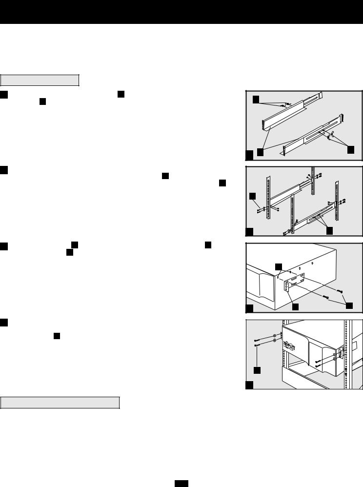
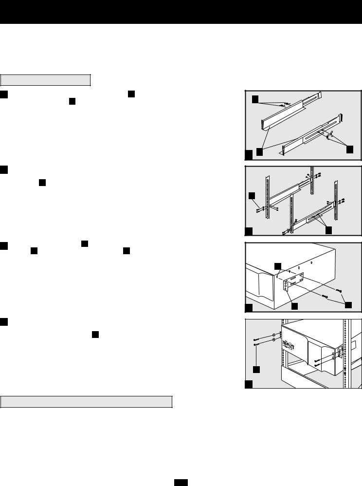
Mounting (Rack)
Mount your equipment in either a 4-post or 2-post rack or rack enclosure.The user must determine the fitness of hardware and procedures before mounting. If hardware and procedures are not suitable for your application, contact the manufacturer of your rack or rack enclosure. The procedures described in this manual are for common rack and rack enclosure types and may not be appropriate for all applications.
4-Post Mounting
1Connect the two segments of each shelf A using the included attached screws and wing nuts B . Leave the screws slightly loose so that the shelves can be adjusted in the next step.
2Adjust each shelf to fit your rack, then mount them in the lowest available space of your rack with the screws, nuts and washers provided C . Note that the support ledges should face inward. Tighten the wingnuts that connect the shelf segments D .
|
B |
|
1 |
A |
B |
|
||
|
|
C |
|
2 |
D |
3Attach mounting ears E to the front mounting holes of your equipment the screws provided G . The ears should face forward.
F using |
|
|
|
F |
|
3 |
E |
G |
4Using an assistant, lift your equipment and slide it onto the mounting shelves. Attach your equipment to the rack by passing the screws, nuts and washers (user-provided) H through its mounting ears and into the rack rails.
H |
4 |
2-Post (Telecom) Mounting
To mount your equipment in a 2-post rack, you must purchase a Tripp Lite 2-Post Rackmount Installation Kit (model: 2POSTRMKIT, sold separately) for each module installed. See the Installation Kit's owner's manual for complete mounting instructions.
3

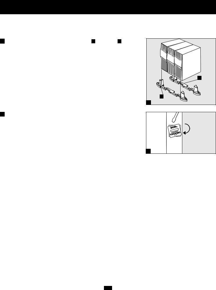
Mounting (Tower)
Mount all modules in an upright, tower position using included base stands. The user must determine the fitness of hardware and procedures before mounting.
1The UPS system is shipped with two sets of plastic feet A and extensions B that can be used to tower mount the UPS’s power module, a battery module and either an isolation transformer module or a second battery module.
Adjust the feet to a width of 10.25 inches (26 cm) for a UPS power module and battery module, or to a width of 15.375 inches (39 cm) for three units. Align the feet in your installation area, approximately 10 inches (26 cm) apart. Have one or more assistants help you place the units on their sides in the feet. The control panel of the UPS should be the UPS’s upper corner and face outward. If you are installing a transformer module, place it between the UPS power module and its battery module.
B
A 
1
2Rotate the power module’s Control Panel to view it easier while the UPS is tower mounted. Insert a small screwdriver, or other tool, in the slots on either side of the Control Panel. Pop the panel out; rotate it; and pop the panel back into place.
2
4
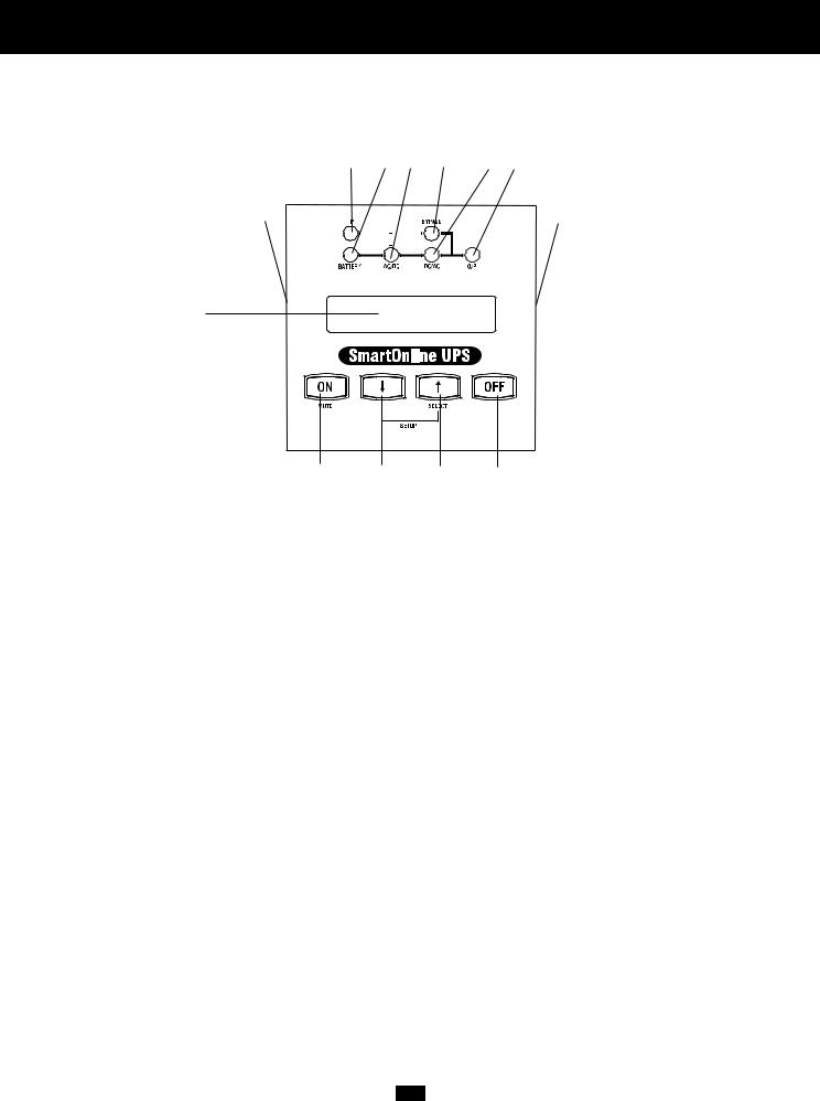
Features
There are three separate UPS system modules available from Tripp Lite (a power module, an isolation transformer module and a battery module) used in a variety of combinations. Familiarize yourself with the location and function of the features on each module before installing and operating your UPS system. The power module is the only module which includes front panel features.
Power Module Front Panel Controls |
11 10 9 8 |
7 6 |
||||
12 |
|
|
|
|
|
12 |
|
|
|
|
|
||
|
|
|
|
|
|
|
|
|
|
|
|
|
|
1
2 |
3 |
4 |
5 |
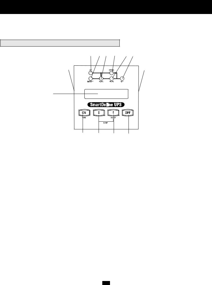
1.LCD DISPLAY: This backlit (16 × 2 character) dot matrix display indicates a wide range of UPS operating conditions and diagnostic data. It also displays UPS settings and options when the UPS is in setup mode.
2.ON/MUTE BUTTON: Press this button and hold it until you hear a beep to turn the UPS system’s inverter ON. If the UPS’s battery alarm is sounding, press this button to silence it.
3.SCROLL DOWN/EXIT SETUP BUTTON: This button allows you to browse through different options and power readings on the LCD display. Momentarily pressing it causes the LCD screen to display a different power reading (see “Operation”, pg. 18). Pressing it and the SCROLL UP Button together puts the UPS in setup mode, where this button is used to scroll through setup options and to exit setup mode.
4.SCROLL UP/SELECT BUTTON: This button allows you to browse through different options and power readings on the LCD display. Momentarily pressing it causes the LCD screen to display a different power reading (see “Operation”, pg. 18). Pressing it and the SCROLL DOWN Button together puts the UPS in setup mode, where this button is used to select setup options.
5.OFF BUTTON: Press this button until you hear a beep to turn the UPS system’s inverter OFF.
6.O/P (OUTPUT) LED: This green light will illuminate to indicate your UPS is supplying AC power to connected equipment.
7.DC/AC (INVERTER) LED: This green light will illuminate to indicate the UPS’s DC/AC inverter is activated.
8.BYPASS LED: This green light will illuminate when the UPS is providing filtered mains power without engaging its converter or inverter. If this LED is lit, connected equipment will not receive battery power in the event of a blackout.
9.AC/DC (Converter) LED: This green light will illuminate to indicate the UPS’s AC/DC converter is charging the connected battery pack(s).
10.BATTERY LED: This red light will illuminate when the UPS is discharging the battery to provide connected equipment with AC power. An alarm will sound which can be silenced by pressing the ON/MUTE Button. This LED will remain lit after the alarm is silenced.
11.I/P (INPUT) LED: This green light will illuminate to indicate an AC input supply is present.
12.ACCESS SLOTS: To rotate the controls, insert a flathead screwdriver into these slots and gently lever the panel out. Taking care not to excessively twist or yank the cables connecting the controls to the rest of the UPS, turn the controls to the desired orientation and reinsert them.
5
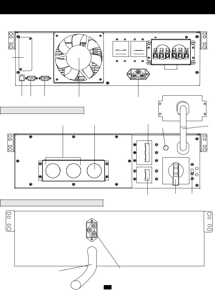
Features (Rear Panel) see page 8 for feature descriptions
6kVA Power Module |
5 |
|
|
4 |
|
1 |
2 |
||||||||||
|
|
|
|
|
|
|
|
|
|
|
|
|
|
|
|
|
|
|
|
|
|
|
|
|
|
|
|
|
|
|
|
|
|
|
|
|
|
|
|
|
|
|
|
|
|
|
|
|
|
|
|
|
|
|
|
|
|
|
|
|
|
|
|
|
|
|
|
|
|
|
|
|
|
|
|
|
|
|
|
|
|
|
|
|
|
|
|
|
|
7
8 |
9 |
10 |
6 |
3 |
6kVA Isolation Transformer Module
12 |
11 |
17 |
15 |
13 |
16 |
18 |
19 |
Battery Module for 6kVA and 10kVA Models
21 |
20 |
6

Features (Rear Panel) see page 8 for feature descriptions
10kVA Power Module |
6 |
5 |
4 |
3 |
|
|
|
|
|
7 |
|
|
|
|
8 |
9 |
10 |
1 |
2 |
10kVA Isolation Transformer Module |
17 |
15 |
12 |
11 |
14 |
16 |
18 |
19 |
Battery Module for 6kVA and 10kVA Models
21 |
20 |
7

Features (Rear Panel) continued
Power Module Feature Description (6kVA and 10kVA models)
1.Output Terminal Block: Use these terminals to connect your power module to your equipment or to the transformer module. Unscrew and remove the cover over the block for access.
2.Input Terminal Block: Use these terminals to connect your power module to utility power or to the transformer module. Unscrew and remove the cover over the block for access.
3.External Battery Connector: Use this to connect one or more Tripp Lite battery modules to the power module. Remove the cover for access. The power module will not start without a connection to a charged battery module. Refer to the battery module owner’s manual for connection instructions and safety warnings.
4.AC Input Breaker: One double-pole circuit breaker controls input power to the power module.
5.AC Output Breaker: One double-pole circuit breaker controls output power from the power module.
6.Exhaust Fan: This cools and ventilates the inside of the power module.
7.Accessory Slot: Remove the small cover panel to install optional accessories to remotely control and monitor your UPS system. Visit Tripp Lite on the Web (www.tripplite.com) to learn about available SNMP, network management and connectivity products that may be installed in this slot.
8.EPO (Emergency Power Off) Port: The power module features an EPO port that may be used to connect the power module to a contact closure switch to enable emergency power off. See “Optional Connection” section for details.
9.RS-232 Communication Port: This female DB9 serial port may be used to connect your UPS to a workstation or server. It uses RS-232 protocol to communicate with a connected computer. It is used with Tripp Lite software and the included serial cable to monitor and manage the UPS remotely over a network and to automatically save open files and shut down equipment during a blackout. See “Optional Connection” for details.
10.Dry Contact Interface Port: This female DB9 port sends contact-closure signals to indicate line-fail and low-battery status. See “Optional Connection” for details.
Isolation Transformer Module Feature Description (6kVA and 10kVA models)
11.Utility Input Terminal Block: Use these terminals to connect your transformer module to utility power. Unscrew and remove the cover over the block for access.
12.Equipment Output Terminal Block: Use these terminals to connect your equipment to the transformer module. Unscrew and remove the cover over the block for access.
13.Cable for Power Module Connection (6kVA models only): Connects the transformer module to the power module’s input/output after the power module’s terminal blocks have been removed. See “Connection” section for details.
14 Hardwire Terminal Block for Power Module Connection (10kVA models only): Use these terminals to connect the transformer module to the power module’s input and output terminal blocks. See “Connection” section for details.
15.Overtemperature Reset Breaker: This circuit breaker trips if the unit’s temperature climbs too high.
16.AC to UPS Breaker: One double-pole circuit breaker controls the transformer module’s power output to the UPS.
17.Output Breaker: One triple-pole circuit breaker controls the transformer module’s power output to connected equipment.
18.Manual Bypass Switch: This red and yellow dial is used to circumvent the power module while still supporting connected equipment when performing power module maintenance. While this switch is on BYPASS, connected equipment will receive filtered AC mains power from the transformer module, but the equipment will not receive battery power in the event of a blackout. See “Manual Bypass Operation” section for complete bypass procedure.
WARNING! For qualified service personnel only. Failure to follow the bypass procedure completely will not adequately power down the UPS power module, resulting in the continued risk of death or injury from potential contact with high voltage.
19.Input Voltage Select Switch: Use this switch to set the transformer module's input voltage (either 200V AC, 208V AC or 240V AC). See “Connection” section for details.
Battery Module Feature Description (6kVA and 10kVA models)
20.Input Connector: Use this connector to daisy chain additional battery modules onto the first. Remove the cover panel for access. Refer to the battery module owner’s manual for connection instructions and safety warnings.
21.Output Cable: Use this cable to connect the battery module to the power module or to another battery module. The power module will not start without a connection to a charged battery module. Refer to the battery module owner’s manual for connection instructions and safety warnings.
8
Connection
Hardwiring Cautions
•Wiring must be done by a qualified electrician.
•The UPS power module may be installed on its own or connected to an isolation transformer module. Both applications require the power module to be connected to a battery module.
•When making wiring connections, observe the cable connection regulations appropriate to your area [e.g. National Electrical Code (NEC) in the U.S.] at all times. Be sure to install an easily accessible disconnect switch in your installation wiring so you may cut off the UPS’s AC input during fires and other emergencies. Ensure that cables are fitted with cable sleeves and are secured by connector clamps. Tighten connections with a torque of not less than 24-28 inch-pounds (2.7-3.2 NM).
•Make sure that your equipment is properly grounded.
•Using cables of improper size may damage your equipment and cause fire hazards. Choose appropriate cabling and protection circuits to make wiring connections (Ground conductors must be the same size and type as the power conductors used):
|
RATED INPUT CURRENT |
RATED OUTPUT CURRENT |
RATED OUTPUT CURRENT |
OUTPUT PROTECTION |
|
200 - 240 (1Ø, 2-Wire + PE) |
200 - 240V (1Ø, 2-Wire + PE) |
120V (1Ø, 2-Wire + PE) |
CIRCUIT |
6kVA Models |
30A 8 AWG (10mm2) |
30A 8 AWG (10mm2) |
2 × 30A 8 AWG (10mm2) |
30A |
10kVA Models |
50A 6 AWG (16mm2) |
50A 6 AWG (16mm2) |
2 × 50A 6 AWG (16mm2) |
63A |
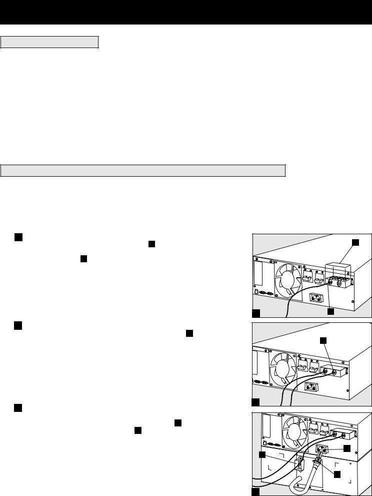
Connecting Modules to Each Other and to Utility Power and Equipment
There are three separate UPS system modules available from Tripp Lite (a power module and a battery module, which are required in all applications, and an isolation transformer module) used in a variety of combinations. Follow the connection procedure below which matches the combination of modules which you plan on installing.
Connection Combination #1:
Power Module (either 6kVA or 10kVA) + Battery Module(s)
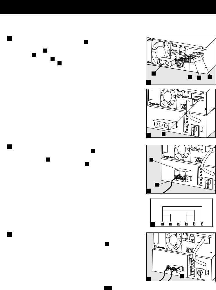
1 Hardwire the power module to your equipment.
Using a screwdriver, remove the top of the box A covering the power module’s input and output terminals. Pass a user-supplied cable through the terminal box’s left knockout B and connect it to the power module’s output terminals. Connect the other end of the cable to your equipment.
2 Hardwire the power module to a utility power source.
Pass a user-supplied cable through the box’s right knockout C and connect it to the power module’s input terminals. Replace the top of the terminal box. Connect the other end of the cable to a utility power source.
3 Connect the battery module to the power module.
Consult the owner’s manual that came with your battery module. Fully insert the connector on the end of the battery module’s cable D into the connector
on the rear panel of the power module E . Small sparks may occur; this is
normal. NOTE: the power module does not contain internal batteries and will not start until a battery module is connected. The battery modules are fully charged prior to shipping. However, before expecting full backup capability (particularly if the battery module has been stored for an extended period) after the UPS system is connected to a utility power source, allow the battery module to recharge for 12 hours. Once the UPS system is in use, it will charge the batteries and maintain the charge level automatically. If needed, connect additional battery modules in a daisy-chain with each module’s cable inserted into the previous module’s
connector |
F |
. |
9 |
6kVA Power Module Shown
|
A |
1 |
B |
|
C |
2 |
E |
F |
D |
3 |
Connection continued
Connection Combination #2:
Power Module (6kVA) + Transformer Module (6kVA) + Battery Module(s)
1 Connect the power module to the transformer module.
Using a screwdriver, remove the entire box A covering the power module’s input and output terminals. Remove the screws on either side of the terminals. Grip the terminals B and slide them out until you can view the cable connector release tab C . Press the tab down and pull on the cables to release them from the internal connector D . Remove the terminals. Insert the connector cable from the transformer module E into the internal connectors in the power module’s terminal box until the release tab clicks in place. Replace the screws around the plate. Although they are not needed, retain the power module’s terminals and terminal box cover in case you plan to operate the power module without the transformer module at a future date.
2 Hardwire the transformer module to your equipment.
Using a screwdriver, remove the top of the box F covering the transformer
module’s input and output terminals. Pass a user-supplied cable through the box’s left knockout G and connect it to the transformer module’s output terminals. See the AC Output Voltage Diagram H to determine which terminal connections will provide voltage appropriate to your application. Connect the other end of the cable to your equipment.
A |
|
D |
B |
C |
|
1 |
|
|
|
NORMAL |
|
BY |
|
PASS |
1 |
E |
|
F |
|
NORMAL |
|
BY |
|
PASS |
|
G |
2 |
|
|
AC OUTPUT VOLTAGE DIAGRAM |
|
|
|
208V |
|
|
240V |
|
120V |
120V |
|
|
G |
|
H |
|
3 Hardwire the transformer module to a utility |
|
|
power source. |
|
|
Pass a user-supplied cable through the box’s right knockout I |
and connect it to |
|
the transformer module’s input terminals. Replace the top of the box covering |
|
|
the transformer module’s terminals. Connect the other end of the cable to a utility |
|
|
power source. |
|
|
|
|
NORMAL |
|
|
BY |
|
|
PASS |
Connection Combination #2 continued on next page |
3 |
I |
|
||
10
Connection continued
4 Select the transformer module’s input voltage.
Using a screwdriver, remove the panel covering the transformer module’s Input Voltage Select Switch J . Set the switch to match your facility’s input voltage. Then, use the power module’s front panel switches to configure input voltage on the LCD Display (see “Configure your UPS’s input and output” in the “Power ON/OFF” section on page 14).
IMPORTANT NOTE: if your facility’s input voltage is 200VAC, set the transformer module’s switch to 240VAC, but configure the power module to 200V AC. If your facility’s input voltage is either 208V AC or 240V AC, the transformer module and power module settings must match. The factory default settings for both modules is 208V. See chart below.
NORMAL |
240V AC |
|
|
BY |
|
|
PASS |
|
|
208V |
AC |
|
|
J |
4 |
|
|
|
Transformer Module |
Power Module |
Your Facility's |
Input Voltage Setting |
Input Voltage Setting |
Input Voltage |
(Rear Panel Switch) |
(Front Panel Switches/LCD Display) |
240V AC |
240V AC |
240V AC |
208V AC |
208V AC |
208V AC |
200V AC |
240V AC |
200V AC |
5 Connect the battery module to the power module.
Consult the owner’s manual that came with your battery module. Fully insert the connector on the end of the battery module’s cable K into the connector on the rear panel of the power module L . Small sparks may occur; this is normal. NOTE: the power module does not contain internal batteries and will not start until a battery module is connected. The battery modules are fully charged prior to shipping. However, before expecting full backup capability (particularly if the battery module has been stored for an extended period) after the UPS system is connected to a utility power source, allow the battery module to recharge for 12 hours. Once the UPS system is in use, it will charge the batteries and maintain the charge level automatically. If needed, connect additional battery modules in a daisy-chain with each module’s cable inserted into the previous module’s connector M .
|
L |
|
K |
|
NORMAL |
5 |
M |
|
Connection Combination #3: Power Module (10kVA) + Transformer Module (10kVA) + Battery Module(s)
1 Hardwire the power module to the transformer module.
Using a screwdriver, remove the top of the box A covering the power module’s input and output terminals. Remove the top of the box B covering the transformer module’s terminals. With supplied cable, connect the power module’s input and output terminals to the corresponding terminals on the transformer module’s “Hardwire Terminal Block for Power Module Connection” in the box’s right knockout C .
2 Hardwire the transformer module to your equipment.
Pass a user-supplied cable through the box’s left knockout D and connect it to the transformer module’s output terminals. See the AC Output Voltage Diagram E to determine which terminal connections will provide voltage appropriate to your application. Connect the other end of the cable to your equipment.
|
A |
|
|
B |
|
|
|
NORMAL |
1 |
C |
BY |
PASS |
||
|
|
NORMAL |
|
BY |
|
PASS |
2 |
D |
AC OUTPUT VOLTAGE DIAGRAM
208V
240V
120V 120V
Connection Combination #3 continued on next page
G
11 |
E |
|

Connection continued
3 Hardwire the transformer module to a utility power source.
Pass a user-supplied cable through the box’s middle knockout F and connect it to the transformer module’s input terminals. Connect the other end of the cable to a utility power source. Replace the top of the boxes covering the power module’s and transformer module’s terminals.
4 Select the transformer module’s input voltage.
Using a screwdriver, remove the panel covering the transformer module’s Input Voltage Select Switch G . Set the switch to match your facility’s input voltage. Then, use the power module’s front panel switches to configure input voltage on the LCD Display (see “Configure your UPS's input and output” in the “Power ON/OFF” section on page 14).
IMPORTANT NOTE: if your facility's input voltage is 200VAC, set the transformer module’s switch to 240VAC, but configure the power module to 200V AC. If your facility’s input voltage is either 208V AC or 240V AC, the transformer module and power module settings must match. The factory default settings for both modules is 208V. See chart below.
|
|
NORMAL |
|
|
BY |
|
|
PASS |
3 |
F |
|
|
|
|
NORMAL |
240V AC |
|
|
BY |
|
|
PASS |
|
|
208V |
AC |
|
|
G |
4 |
|
|
|
Transformer Module |
Power Module |
Your Facility’s |
Input Voltage Setting |
Input Voltage Setting |
Input Voltage |
(Rear Panel Switch) |
(Front Panel Switches/LCD Display) |
240V AC |
240V AC |
240V AC |
208V AC |
208V AC |
208V AC |
200V AC |
240V AC |
200V AC |
5 Connect the battery module to the power module.
Consult the owner’s manual that came with your battery module. Fully insert
the connector on the end of the battery module’s cable H into the connector on the rear panel of the power module I . Small sparks may occur; this is normal. NOTE: the power module does not contain internal batteries and will not supply power to connected equipment until a battery module is connected. The battery modules are fully charged prior to shipping. However, if the battery module has been stored for an extended period, after the UPS system is connected to a utility power source, allow the battery module to recharge for 12 hours. If needed, connect additional battery modules in a daisy-chain with each module’s cable inserted into the previous module’s connector J .
I 
H |
5 J
12
Optional Connection
The following connections are optional. Your UPS system will function properly without these connections.
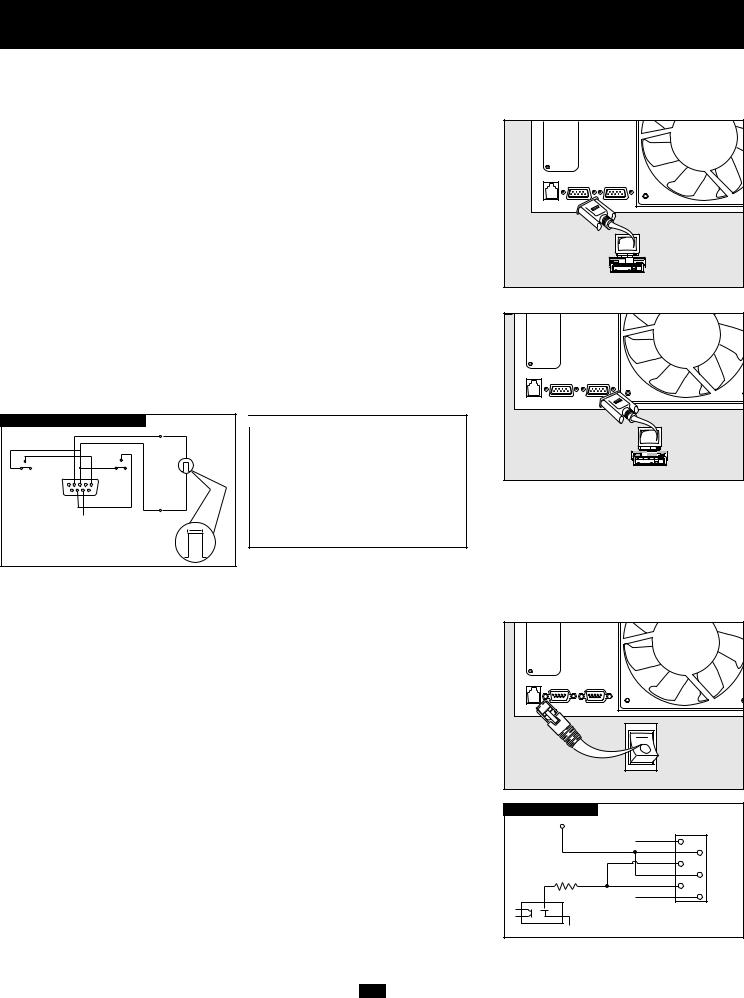
RS-232 Serial Communication Connection
Use the included cable to connect the power module’s “RS-232” port to the communication port on your computer. This will allow full network monitoring and control of your UPS system. Install on your computer the Tripp Lite PowerAlert Software appropriate to your computer’s operating system.
Contact-Closure Communication Connection
Use a user-supplied contact-closure DB9 cable to connect the power module’s “DryContact” port to the communication port on your computer or other equipment. This will allow basic contact-closure signals to be sent to and from the UPS. Refer to the following diagram and table to determine the signals carried by this port. Install on your computer theTripp Lite PowerAlert Software appropriate to your computer’s operating system.
DRY CONTACT INTERFACE DIAGRAM
|
|
|
|
|
|
|
lm in. > 3.3 mA |
|
|
|
|
|
|
|
|
|
|
LOW BATTERY |
|
|
|
|
|
|
|
|
|
|
|
|
|
|
BACK-UP |
REMOTE SHUTDOWN SIGNAL |
|
|
|
|
|
|
|
FROM EXTERNAL |
||
NO |
|
|
|
|
|
|
NO |
|
|
|
|
|
|
|
|
|
|
COM NC |
|
|
|
|
|
COM |
NC |
|
5 |
9 4 |
8 |
3 |
7 2 |
6 |
1 |
|
|
|
|
|
|
|
|
|
|
|
|
|
|
|
SIGNAL FROM COMPUTER |
|
|
||
|
|
|
|
|
|
|
>2 sec |
|
|
|
|
|
|
|
|
|
|
|
|
|
|
|
|
|
|
12 V |
MAXIMUM CAPACITY OF DRY CONTACT: AC250V/3A • DC30V/3A |
|
|
||||||
|
|
|
|
|
|
|
|
0 |
|
DRY CONTACT INTERFACE TABLE |
|
|
|
|
|
|
|
|
|
||
|
UPS Operating |
Pin 8,3 |
Pin 1,3 |
Pin 6,3 |
|
|
||||||
|
Mode |
|
|
|
|
|
|
|
|
|
|
|
|
Normal |
OPEN |
OPEN |
* |
|
|
|
|
|
|
|
|
|
Back Up |
CLOSE |
* |
* |
|
|
|
|
|
|
|
|
|
Low Battery |
CLOSE |
CLOSE |
* |
|
|
|
|
|
|
|
|
|
Fault |
* |
* |
CLOSE |
|
|
|
|||||
* Inactive: may be in either state
EPO Port Connection
This optional feature is only for those applications which require connection to a facility’s Emergency Power Off (EPO) circuit. When the power module is connected to this circuit, it enables emergency shutdown of the output. Using the included cable, connect the power module’s EPO port to a user-supplied remote switch. The pin assignments for the EPO port are shown in the following diagram. Note: if there is a short between pins 2 and 3, 2 and 5, 4 and 5, or 3 and 4, the UPS system will power off.
EPO PIN ASSIGNMENT
12V |
|
X |
1 |
|
|
|
2 |
|
3 |
|
4 |
1K |
5 |
|
|
X |
6 |
|
|
|
|
|
|
13
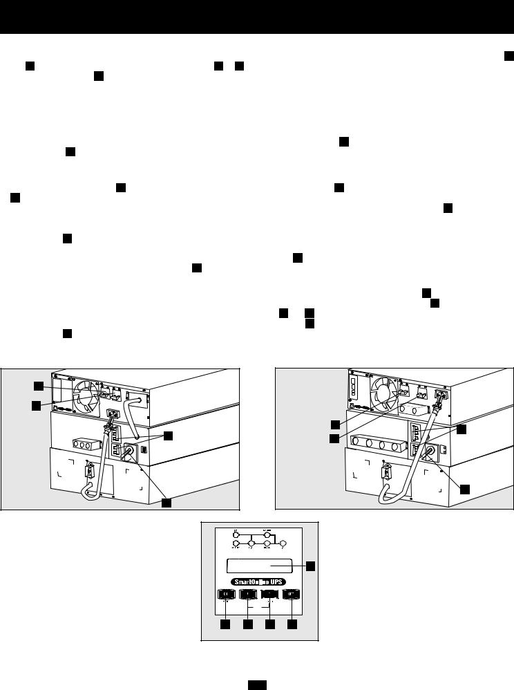
Power ON/OFF
1.Configure your UPS’s input and output: Put your UPS power module into setup mode by holding down both of its scroll buttons ( A and B ) at once. Scroll through the setup options (using A or B ) and select the appropriate setting for each of the following options using the “SELECT” button B .
•Input & Output Voltage: Select 200, 208 or 240 VAC.
•Output Frequency: Your UPS will autoselect 50 or 60 Hz to match the input.
•Economy Mode: Your UPS can provide on-line operation with zero transfer time. It can also operate in a more energy-efficient line-interactive mode. Select Economy On to put the UPS in line-interactive mode. Select Economy Off to put the UPS in on-line mode.
•After you have set these options, “exit” the setup mode with the scroll button A , then exit bypass mode by holding the ON button C down until you hear a beep.
2.Turn input to the UPS ON: If the UPS power module is connected to a transformer module, turn the tranformer module’s AC-to-UPS
and Output Circuit Breakers D on. Turn the UPS power module’s Input Circuit Breaker E on. Press the UPS power module’s ON button C until you hear a beep to begin inverter operation. If your AC input is not providing power normally, you may “cold start” your UPS from battery. (Your battery must be at least partially charged for this operation to succeed.) Press and hold the “ON” C button until you hear a beep to start your UPS in ON BATTERY mode. Note that some electronic equipment may draw more amps during startup; when starting from battery, consider reducing the initial load on the UPS. Your UPS will perform a brief self-test and show the results on the LCD Display F . See “Startup Self-Test” in the “Operation” section for the display sequence.
3.Turn UPS output ON: Turn the UPS power module’s Output Circuit Breaker H ON. If the UPS is connected to a transformer module, turn the transformer module’s Manual Bypass Switch I from BYPASS to NORMAL and its Output Circuit Breaker ON. Your UPS will now provide power to connected equipment.
4.To turn the UPS power module and transformer module OFF: Press the UPS power module’s OFF button E until you hear a beep. Your load will still be energized. The inverter is now off, but your UPS is not fully deactivated. The LCD Display F will show BYPASS MODE. Turn the UPS power module’s Input and Output Circuit Breakers ( E and H ) OFF. If the UPS is connected to a transformer module, turn the transformer module’s power AC-to-UPS and Output Circuit Breakers D OFF. Your load will no longer be energized, and the LCD Display F will be dark.
H
E
|
H |
D |
D |
|
|
E |
|
|
|
|
I
I
6kVA Models |
10kVA Models |
|
|
|
F |
C |
A |
B |
E |
6kVA & 10kVA Models (Front Panel)
14
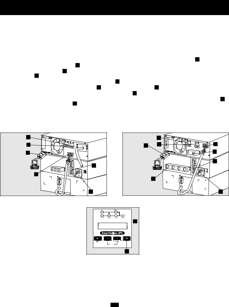
Manual Bypass Operation (for power module maintenance or replacement)
The following procedure only applies to UPS system configurations that include a 6kVA or 10kVA transformer module. The procedure details how to service or replace the power module while supplying equipment connected to the transformer module with utility power. NOTE: since the power module and battery module will be disconnected during the procedure, they will be unable to supply battery backup support to equipment connected to the transformer module in the event of a blackout.
WARNING! For qualified service personnel only. Failure to follow this procedure completely will not adequately power down the UPS power module, resulting in the continued risk of death or injury from potential contact with high voltage.
1.Disable PowerAlert Software and disconnect communication cable from the power module’s communication ports A .
2.Turn transformer module’s Bypass Switch B to “BYPASS”.
3.Press power module’s OFF Button C , if power module is powered, until a beep is heard and a “BYPASS MODE” message is displayed in the LCD panel D .
4.Turn off the transformer module's double-pole AC to UPS breaker E .
5.Turn off the power module’s double-pole input breaker F and double-pole output breaker G .
6.Disconnect battery module cable from the power module’s battery connector H .
7.FOR 10kVA POWER MODULES ONLY: Use a voltage meter to check the cable connecting the power module’s terminal blocks I to the transformer module’s terminal blocks J to ensure the power module is no longer powered. Once it is no longer powered, remove the cabling.
The power module is now safely powered down and maintenance/replacement can be performed.
G |
|
G |
F |
A |
F |
A |
|
|
|
E |
|
H
J |
E
NORMAL
H |
|
|
I |
B |
B |
6kVA Models (Rear Panel) |
10kVA Models (Rear Panel) |
 D
D
C
6kVA & 10kVA Models (Front Panel)
15
Operation
Startup Self-Test
When you turn the UPS ON, it will enter Diagnostic Mode and perform a brief self-test lasting about 15 seconds. The results of the self-test are shown on the LCD screen in the sequence below.
STARTED WITH
AC INPUT
DIAGNOSTIC MODE
FREQ OUT = XXHz
▼
DIAGNOSTIC MODE
INPUT AC OK
▼
DIAGNOSTIC MODE
INPUT AC OK
▼
DIAGNOSTIC MODE
BATTERY OK
▼
DIAGNOSTIC MODE
CHARGER OK
▼
DIAGNOSTIC MODE
AC/DC OK
▼
DIAGNOSTIC MODE TESTING INVERTER
▼
ONLINE MODE
LOAD = XXX% X.XXKW
COLD
START*
DIAGNOSTIC MODE
FREQ OUT = XXHz
▼
DIAGNOSTIC MODE
INPUT AC BAD
▼
DIAGNOSTIC MODE
INPUT AC BAD
▼
DIAGNOSTIC MODE
BATTERY OK
▼
DIAGNOSTIC MODE
AC/DC OK
▼
DIAGNOSTIC MODE TESTING INVERTER
▼
ON BATTERY MODE LOAD = XXX% X.XXKW
*Note: If the UPS is cold started, its BATTERY LED will be lit.
Failed Self-Test
If a problem is detected during the self-test, the LCD will display a error message. If your UPS displays any of the following messages in its LCD, call Tripp Lite Technical Support at (773) 869-1234 for service.
BAD BATTERY!
CALL FOR SERVICE
CHARGER FAILURE!
CALL FOR SERVICE
AC/DC FAILURE!
CALL FOR SERVICE
INVERTER FAILURE!
CALL FOR SERVICE
OUTPUT FAILURE!
CALL FOR SERVICE
FAN FAILURE!
CALL FOR SERVICE
16
Operation continued
Normal Operation
During normal operation, the first line of your LCD Display shows which operating mode your UPS is in: Online, Economy, On Battery, or Bypass.
Online mode: The UPS provides AC power while utility power is available and switches to On Battery mode instantly (zero transfer time) if AC power is interrupted.
Economy mode: The UPS provides AC power at high efficiency while utility power is available and switches to On Battery mode quickly if AC power is interrupted.
On Battery mode: The UPS provides AC power from battery backup so long as battery power lasts. It switches back to Online or Economy mode if utility power is available and shuts down if it runs out of battery power.
Bypass mode: The UPS provides AC power while utility power is available. The UPS shuts down if AC power is interrupted.
The second line of the LCD Display shows basic power conditions. Push the SCROLL buttons to browse through these basic power conditions in the sequence shown below.
▼
XXXXMODE LOAD = XXX% X.XXKW
▼▲
XXXXMODE
IN = XXXV XX.X Hz
▼▲
XXXXMODE OUT = XXXV XX.X Hz
▼▲
XXXXMODE BATTERY = XXXVDC
▼
On Battery Alarm
When in the On Battery mode, the UPS power module will beep to inform you that it is using battery power to support connected equipment. If its connected batteries are at more than half capacity, it will beep every two seconds. If its connected batteries are below half capacity, it will beep twice a second. If its connected batteries are nearly depleted, the UPS power module will beep continuously.
To silence the On Battery Alarm, press the “ON/MUTE” button.
Overload Messages
When the UPS detects an output overload, its LCD will switch to the following display:
OVERLOAD!
LOAD = XXX% X.XXKW
The UPS will then begin a countdown. If the UPS is still overloaded at the end of the countdown, the UPS will automatically go to Bypass Mode to protect its inverter. The duration of the countdown varies with the severity of the overload, as follows:
|
Overload Condition |
Countdown Duration |
|
|
102% - 125% |
1 minute |
|
|
125% - 150% |
30 seconds |
|
>150% |
Immediate |
||
|
|
|
|
17

Operation continued
Bypass Messages
While in Bypass Mode, the UPS monitors its input voltage and passes that input power along to connected equipment. The UPS will not provide battery backup in Bypass Mode.
If the output voltage deviates from an acceptable range (between 15% higher and 20% lower than nominal), the UPS displays the condition on its LCD and stops supplying output power to its load. If power levels return to an acceptable level, the UPS resumes supplying power to the load, and its LCD reports that output voltage was too high or too low at one time, but has returned to nominal.
|
|
BYPASS VOLTAGE |
|
LCD DISPLAY |
|
|
|
|
CONDITIONS |
|
MESSAGES |
|
|
|
|
|
|
|
|
|
|
|
>15% Higher |
|
|
|
|
|
|
|
NO OUTPUT |
|
|
|
|
|
Than Nominal |
|
BYPASS AC TOO HI |
|
|
|
|
|
|
|
|
|
|
|
|
|
|
|
|
|
|
>20% Lower |
|
|
|
|
|
|
|
NO OUTPUT |
|
|
|
|
|
Than Nominal |
|
BYPASS AC TOO LO |
|
|
|
|
|
|
|
|
|
|
|
|
|
|
|
|
|
|
|
|
|
|
|
|
|
Was Too High, |
|
BYPASS MODE |
|
|
|
|
Now Nominal |
|
BYPASS AC WAS HI |
|
|
|
|
|
|
|
|
|
|
|
|
|
|
|
|
|
|
|
|
|
|
|
|
|
Was Too Low, |
|
BYPASS MODE |
|
|
|
|
Now Nominal |
|
BYPASS AC WAS LO |
|
|
|
|
|
|
|
|
|
|
|
|
|
|
|
|
Shutdown Messages
Your UPS will shut down and the LCD will display a message if it detects one of the following conditions. Note: During all these conditions, the “Input,” “Output” and “Bypass” LEDs will be illuminated.
|
SHUTDOWN |
|
LCD DISPLAY |
|
|
CONDITIONS |
|
MESSAGES |
|
|
|
|
|
|
|
|
|
|
|
|
Extended |
|
SHUT DOWN |
|
|
Overload |
|
OVERLOAD XXX% |
|
|
|
|
|
|
|
|
|
|
|
|
|
|
|
|
|
Output Short |
|
SHUT DOWN |
|
|
Circuit |
|
O/P SHORT CIRCUIT |
|
|
|
|
|
|
|
|
|
|
|
|
|
|
|
|
|
Remote Shutdown |
|
SHUT DOWN |
|
|
Command (Via DB9) |
|
REMOTE COMMAND |
|
|
|
|
|
|
|
|
|
|
|
|
|
|
|
|
|
Remote Shutdown |
|
SHUT DOWN |
|
|
Command (Via EPO) |
|
EMERGENCY STOP! |
|
|
|
|
|
|
|
|
|
|
|
|
|
|
|
|
|
Internal |
|
SHUT DOWN |
|
|
Faults |
|
+ DC BUS HIGH |
|
|
|
|
|
|
|
|
|
SHUT DOWN |
|
|
|
|
+ DC BUS LOW |
|
|
|
|
|
|
|
|
|
|
|
|
|
|
SHUT DOWN |
|
|
|
|
- DC BUS HIGH |
|
|
|
|
|
|
|
|
|
|
|
|
|
|
SHUT DOWN |
|
|
|
|
- DC BUS LOW |
|
|
|
|
|
|
|
|
|
|
|
|
|
|
SHUT DOWN |
|
|
|
|
OVERTEMPERATURE |
|
|
|
|
|
|
|
|
|
|
|
18

Service/Warranty and Insurance
Service
Your SmartOnline UPS is covered by the 2-year limited warranty period described below. A variety of service contracts are also available from Tripp Lite, including start-up service contracts and 3- to 5-year SafeSure on-site service contracts. For more information, call Tripp Lite Customer Service at (773) 869-1234.
2-Year Limited Warranty
TRIPP LITE warrants its products including batteries to be free from defects in materials and workmanship for a period of two years from the date of initial purchase. After 90 days from the date of purchase, TRIPP LITE’s obligation under this warranty is limited to replacing parts on such defective products. To obtain service under this warranty, you must call TRIPP LITE or an authorized TRIPP LITE service center. Products must be returned to TRIPP LITE or an authorized TRIPP LITE service center with transportation charges prepaid and must be accompanied by a brief description of the problem encountered and proof of date and place of purchase. This warranty does not apply to equipment which has been damaged by accident, negligence or misapplication or has been altered or modified in any way. This warranty applies only to the original purchaser who must have properly registered the product within 10 days of purchase.
The warranties of all TRIPP LITE surge suppressors are null and void if they have been connected to the output of any UPS system. The warranties of all TRIPP LITE UPS Systems are null and void if a surge suppressor has been connected to its output receptacles.
EXCEPT AS PROVIDED HEREIN, TRIPP LITE MAKES NO WARRANTIES, EXPRESS OR IMPLIED, INCLUDING WARRANTIES OF MERCHANTABILITY AND FITNESS FOR A PARTICULAR PURPOSE. Some states do not permit limitation or exclusion of implied warranties; therefore, the aforesaid limitation(s) or exclusion(s) may not apply to the purchaser.
EXCEPT AS PROVIDED ABOVE, IN NO EVENT WILL TRIPP LITE BE LIABLE FOR DIRECT, INDIRECT, SPECIAL, INCIDENTAL OR CONSEQUENTIAL DAMAGES ARISING OUT OF THE USE OF THIS PRODUCT, EVEN IF ADVISED OF THE POSSIBILITY OF SUCH DAMAGE. Specifically, TRIPP LITE is not liable for any costs, such as lost profits or revenue, loss of equipment, loss of use of equipment, loss of software, loss of data, costs of substitutes, claims by third parties, or otherwise.
The policy of TRIPP LITE is one of continuous improvement. Specifications are subject to change without notice.
Ultimate Lifetime Insurance Policy (Valid in U.S. and Canada ONLY)
Tripp Lite warrants, for the lifetime of the product, (at Tripp Lite's option) to repair or replace (on a pro rata basis) directly connected equipment that is damaged due to power transients while properly connected to Tripp Lite products offering the Ultimate Lifetime Insurance Policy. Power transients include spikes and surges on the AC power, data or telephone lines that the Tripp Lite products have been designed to protect against (as recognized by industry standards).
AC Power Line Transients: To claim damages, the Tripp Lite product must be plugged into a properly wired and grounded outlet. No extension cords or other electrical connections may be used. The installation must comply with all applicable electrical and safety codes set forth by the National Electrical Code (NEC). Except as provided above, this warranty does not cover any damage to properly connected electronic equipment resulting from a cause other than an "AC power transient". If user meets all of the above requirements, Tripp Lite will repair or replace (at Tripp Lite's option) equipment up to the specified value (See Ultimate Lifetime Insurance Policy Limits). No coverage is allowed for damage entering from telephone or data lines, unless they are separately protected, as described below.
Telephone and Data Line Transients: Tripp Lite will repair or replace directly connected equipment that is damaged by transients on telephone and/or data lines only when all such paths are protected by a Tripp Lite protection product(s) and the AC power (utility) line is simultaneously protected by a Tripp Lite power protection device (UPS, surge suppressor or line conditioner) with Ultimate Lifetime Insurance coverage. Additional telephone and/or data line connected devices downstream must have their own telephone and/or dataline protectors.
Reimbursement dollar limits will be equal to that of the Tripp Lite power protection protector. Coverage is excluded where a suitable environment for the protection device is not provided, including, but not limited to, lack of a proper safety ground. Telephone service equipment must also include a properly installed and operating "primary protection" device at the telephone service entrance (such devices are normally added during telephone line installation).
All above warranties are null and void if the Tripp Lite product has been improperly installed, tampered with or altered in any way, or if the connected equipment was not used under normal operating conditions or in accordance with any labels or instructions. All claims under this warranty must be submitted in writing to Tripp Lite within 30 days of the occurrence or the claim will not be considered. This warranty does not include damage resulting from accident or misuse, and applies to the domestic (USA & Canada) use of these products only.
Tripp Lite reserves the right to determine whether the damage to the connected equipment is due to malfunction of the Tripp Lite product by requesting the equipment in question be sent to Tripp Lite for examination. This policy is above and beyond, only to the extent needed, of that provided by any coverage of connected equipment provided by other sources, including, but not limited to, any manufacturer's warranty and/or any extended warranties.
EXCEPT AS PROVIDED ABOVE, TRIPP LITE MAKES NO WARRANTIES, EXPRESS OR IMPLIED, INCLUDING WARRANTIES OF MERCHANTABILITY AND FITNESS FOR A PARTICULAR PURPOSE. Some states do not permit limitation or exclusion of implied warranties; therefore, the aforesaid limitation(s) or exclusion(s) may not apply to purchaser.
EXCEPT AS PROVIDED ABOVE, IN NO EVENT WILL TRIPP LITE BE LIABLE FOR DIRECT, INDIRECT, SPECIAL, INCIDENTAL OR CONSEQUENTIAL DAMAGES ARISING OUT OF THE USE OF THIS PRODUCT, EVEN IF ADVISED OF THE POSSIBILITY OF SUCH DAMAGE. Specifically, Tripp Lite is not liable for any costs, such as lost profits or revenue, loss of equipment, loss of use of equipment, loss of software, loss of data, costs of substitutes, claims by third parties or otherwise. Coverage also does not apply to connected medical and industrial equipment.
To receive service under this warranty, you must be the original purchaser/user of the product in question. You must obtain a Returned Material Authorization (RMA) number from Tripp Lite. Products must be returned to Tripp Lite with transportation charges prepaid and must be accompanied by a brief description of the problem encountered and proof of date and place of purchase.
19

Specifications
SU6000RT3U and SU10KRT3U models include a Power Module, Isolation Transformer Module and one Battery Module. SU6000RT3UXR models include a Power Module, Isolation Transformer Module and two Battery Modules.
Model |
SU6000RT3U |
SU6000RT3UXR |
SU10KRT3U |
|
Input |
|
|
|
|
Input Voltage Range |
156V~276V Single Phase |
156V~276V Single Phase |
156V~276V Single Phase |
|
Module Input Voltage |
200/208/240V |
200/208/240V |
200/208/240V |
|
Input Frequency |
50/60 Hz ± 3 Hz |
50/60 Hz ± 3 Hz |
50/60 Hz ± 3 Hz |
|
Input Current |
22.6A |
22.6A |
40A |
|
Inrush Current |
<150A |
<150A |
<200A |
|
Power Factor (Full Load) |
>0.97 |
>0.97 |
>0.97 |
|
Efficiency (Full Load/On-Line) |
>87% |
>87% |
>88% |
|
Power Module Circuit Breaker |
40A (2 pole) |
40A (2 pole) |
63A (2 pole) |
|
Transformer Module Circuit Breaker |
40A (2 pole) |
40A (2 pole) |
63A (2 pole) |
|
|
|
|
|
|
Output |
|
|
|
|
VA |
6000 |
6000 |
10000 |
|
Watts (Power Factor: 0.7) |
4200 |
4200 |
7000 |
|
Waveform (On-Line) |
Sinewave |
Sinewave |
Sinewave |
|
Waveform (On-Battery) |
Sinewave |
Sinewave |
Sinewave |
|
Output Voltage (RMS) |
100/120/200/208/240V |
100/120/200/208/240V |
100/120/200/208/240V |
|
Output Frequency |
50/60 Hz |
50/60 Hz |
50/60 Hz |
|
|
|
(± 0.2 Hz on battery) |
(± 0.2 Hz on battery) |
(± 0.2 Hz on battery) |
Voltage Regulation |
±3% |
±3% |
±3% |
|
Max. Harmonic Distortion |
|
|
|
|
|
(Linear Full Load) |
<3% |
<3% |
<3% |
|
(Non-Linear Full Load) |
<6% |
<6% |
<6% |
Overload Capabilities |
102% (continuous) |
102% (continuous) |
102% (continuous) |
|
|
|
102%~125% (1 min.) |
102%~125% (1 min.) |
102%~125% (1 min.) |
|
|
125%~150% (30 sec.) |
125%~150% (30 sec.) |
125%~150% (30 sec.) |
|
|
>150% (Immediate) |
>150% (Immediate) |
>150% (Immediate) |
Short Circuit Capability |
90A* |
90A* |
160A* |
|
Power Module Circuit Breaker |
40A |
63A |
63A |
|
Transformer Module Circuit Breaker |
30A (3 pole) |
63A (3 pole) |
63A (3 pole) |
|
Crest Factor |
3:1 |
3:1 |
3:1 |
|
*The short circuit capability at 1ø 2W 120V for the SU6000RT3U and SU6000RT3UXR is greater than 180A, and for the SU10KRT3U is greater than 320A.
Operation
On-Line Transfer Time |
|
|
|
|
(Line to Battery, Battery to Line) |
0 ms |
0 ms |
0 ms |
|
Audible Noise (Full Load @ 1 m) |
<50 dBA |
<55 dBA |
<55 dBA |
|
Typical Backup Time (with included Battery Module) |
|
|
||
|
(Full Load) |
15 min. + |
37 min. + |
8 min. + |
|
(Half Load) |
37 min. + |
79 min. + |
20 min. + |
Indicators
Includes an LCD Display and LEDs (I/P (input), BATTERY, AC/DC, BYPASS DC/AC, O/P (output)).
Communications
Includes an RS-232 DB9 female connector, a dry contact DB9 female connector and an accessory slot.
Physical Specifications
Unit Dimensions (H x W x D) |
|
|
|
Power Module |
5.25 (3U) x 17.5 x 22.5 in. |
5.25 (3U) x 17.5 x 22.5 in. |
5.25 (3U) x 17.5 x 22.5 in. |
|
[13.4 x 44.5 x 57.2 cm.] |
[13.4 x 44.5 x 57.2 cm.] |
[13.4 x 44.5 x 57.2 cm.] |
Transformer Module |
5.25 (3U) x 17.5 x 26 in. |
5.25 (3U) x 17.5 x 26 in. |
5.25 (3U) x 17.5 x 26 in. |
|
[13.4 x 44.5 x 66.1 cm.] |
[13.4 x 44.5 x 66.1 cm.] |
[13.4 x 44.5 x 66.1 cm.] |
Battery Module #1 |
5.25 (3U) x 17.5 x 22.5 in. |
5.25 (3U) x 17.5 x 22.5 in. |
5.25 (3U) x 17.5 x 22.5 in. |
|
[13.4 x 44.5 x 57.2 cm.] |
[13.4 x 44.5 x 57.2 cm.] |
[13.4 x 44.5 x 57.2 cm.] |
Battery Module #2 (if applicable) |
n/a |
5.25 (3U) x 17.5 x 22.5 in. |
n/a |
|
|
[13.4 x 44.5 x 57.2 cm.] |
|
|
|
|
|
Shipping Weight |
|
|
|
Power Module |
58 lb. |
58 lb. |
68 lb. |
|
[27 kg.] |
[27 kg.] |
[31 kg.] |
Transformer Module |
124 lb. |
124 lb. |
124 lb. |
|
[57 kg.] |
[57 kg.] |
[57 kg.] |
Battery Module #1 |
160 lb. |
160 lb. |
160 lb. |
|
[73 kg.] |
[73 kg.] |
[73 kg.] |
Battery Module #2 (if applicable) |
n/a |
160 lb. |
n/a |
|
|
[73 kg.] |
|
+ Backup times are expandable with additional Battery Modules (model: BP240V10RT-3U) sold separately.
20
Specifications continued
SU6000RT3UHV and SU10KRT3UHV models include a Power Module and one Battery Module.
Model |
SU6000RT3UHV |
SU10KRT3UHV |
|
|
Input |
|
|
|
|
Input Voltage Range |
156V~276V Single Phase |
156V~276V Single Phase |
|
|
Module Input Voltage |
200/208/240V |
200/208/240V |
|
|
Input Frequency |
50/60 Hz ± 3 Hz |
50/60 Hz ± 3 Hz |
|
|
Input Current |
22.6A |
40A |
|
|
Inrush Current |
<150A |
<200A |
|
|
Power Factor (Full Load) |
>0.97 |
>0.97 |
|
|
Efficiency (Full Load/On-Line) |
>87% |
>88% |
|
|
Power Module Circuit Breaker |
40A (2 pole) |
63A (2 pole) |
|
|
|
|
|
|
|
Output |
|
|
|
|
VA |
6000 |
10000 |
|
|
Watts (Power Factor: 0.7) |
4200 |
7000 |
|
|
Waveform (On-Line) |
Sinewave |
Sinewave |
|
|
Waveform (On-Battery) |
Sinewave |
Sinewave |
|
|
Output Voltage (RMS) |
200/208/240V |
200/208/240V |
|
|
Output Frequency |
50/60 Hz |
50/60 Hz |
|
|
|
|
(± 0.2 Hz on battery) |
(± 0.2 Hz on battery) |
|
Voltage Regulation |
±3% |
±3% |
|
|
Max. Harmonic Distortion |
|
|
|
|
|
(Linear Full Load) |
<3% |
<3% |
|
|
(Non-Linear Full Load) |
<6% |
<6% |
|
Overload Capabilities |
102% (continuous) |
102% (continuous) |
|
|
|
|
102%~125% (1 min.) |
102%~125% (1 min.) |
|
|
|
125%~150% (30 sec.) |
125%~150% (30 sec.) |
|
|
|
>150% (Immediate) |
>150% (Immediate) |
|
Short Circuit Capability |
90A |
160A |
|
|
Power Module Circuit Breaker |
40A |
63A |
|
|
Crest Factor |
3:1 |
3:1 |
|
|
|
|
|
|
|
Operation |
|
|
|
|
On-Line Transfer Time |
|
|
|
|
(Line to Battery, Battery to Line) |
0 ms |
0 ms |
|
|
Audible Noise (Full Load @ 1 m) |
<50 dBA |
<55 dBA |
|
|
Typical Backup Time (with included Battery Module) |
|
|
||
|
(Full Load) |
15 min. + |
8 min. + |
|
|
(Half Load) |
37 min. + |
20 min. + |
|
|
|
|
|
|
Indicators
Includes an LCD Display and LEDs (I/P (input), BATTERY, AC/DC, BYPASS DC/AC, O/P (output)).
Communications
Includes an RS-232 DB9 female connector, a dry contact DB9 female connector and an accessory slot.
Physical Specifications
Unit Dimensions (H x W x D) |
|
|
|
Power Module |
5.25 (3U) x 17.5 x 22.5 in. |
5.25 (3U) x 17.5 x 22.5 in. |
|
|
[13.4 x 44.5 x 57.2 cm.] |
[13.4 x 44.5 x 57.2 cm.] |
|
Battery Module |
5.25 (3U) x 17.5 x 22.5 in. |
5.25 (3U) x 17.5 x 22.5 in. |
|
|
[13.4 x 44.5 x 57.2 cm.] |
[13.4 x 44.5 x 57.2 cm.] |
|
Shipping Weight |
|
|
|
Power Module |
58 lb. |
68 lb. |
|
|
[27 kg.] |
[31 kg.] |
|
Battery Module |
160 lb. |
160 lb. |
|
|
[73 kg.] |
[73 kg.] |
|
+ Backup times are expandable with additional Battery Modules (model: BP240V10RT-3U) sold separately.
21

22

Manual del propietario
SmartOnline™ monofásico de 6 kVA y 10 kVA
Sistemas UPS inteligentes realmente en línea (Montaje en bastidor/torre)
Para todos los módulos del sistema UPS (módulo de potencia, módulo de transformador de aislamiento y módulo de batería) vendidos por separado o combinados. Los módulos de sistemas UPS exclusivos pueden incluir hojas separadas de instrucciones o de advertencias que deben usarse junto con este manual.
|
|
|
|
|
|
|
|
|
|
|
|
|
|
|
|
|
|
|
|
|
|
|
|
|
|
|
|
|
|
|
|
|
|
|
|
|
|
|
|
|
|
|
|
|
|
|
|
|
|
|
|
|
|
|
|
|
|
|
|
|
|
|
Advertencias de seguridad |
24 |
|||||||
|
|
|
|
|
|
|||
|
|
|
|
|
|
|||
Montaje |
25 |
|||||||
|
|
|
|
|
|
|||
|
|
|
|
|
|
|||
Características |
27 |
|||||||
|
|
|
|
|
|
|||
|
|
|
|
|
|
|
|
|
Conexión |
31 |
|||||||
|
|
|
|
|
|
|||
|
|
|
|
|
|
|||
Conexión opcional |
35 |
|||||||
|
|
|
|
|
|
|||
|
|
|
|
|
|
|||
Encendido y apagado |
37 |
|||||||
|
|
|
|
|
|
|||
|
|
|
|
|
|
|||
Operación de derivación manual |
37 |
|||||||
|
|
|
|
|
|
|||
|
|
|
|
|
|
|
|
|
Operación |
38 |
|||||||
|
|
|
|
|
|
|||
|
|
|
|
|
|
|||
Servicio/Garantía y Seguro |
41 |
|||||||
|
|
|
|
|
|
|||
|
|
|
|
|
|
|||
Especificaciones |
42 |
|||||||
|
|
|
|
|
|
|||
|
|
|
|
|
|
|||
English/Français/Русский |
1/45/67 |
|||||||
|
|
|
|
|
|
|
|
|
1111 W. 35th Street • Chicago, IL 60609 USA
Soporte al cliente: (773) 869-1234 o Servicios de aplicaciones: (773) 869-1236 o www.tripplite.com
Copyright ©2004 Tripp Lite. Todos los derechos reservados

Advertencias de seguridad importantes
GUARDE ESTAS INSTRUCCIONES. Este manual contiene importantes instrucciones y advertencias que debe seguir durante la instalación y el mantenimiento de todos los sistemas UPS SmartOnline de Tripp Lite de montaje en torre o bastidor, y sus baterías.
Advertencias sobre la ubicación del UPS
•Instale su UPS bajo techo, lejos de la humedad, el calor, el polvo, la luz solar directa y los contaminantes conductores.
•Instale su UPS en un área estructuralmente sólida. Su UPS es muy pesado; tenga cuidado al mover y levantar la unidad.
•Sólo opere su UPS a temperaturas bajo techo entre 32° F y 104° F (entre 0° C y 40° C) Para obtener mejores resultados, mantenga las temperaturas bajo techo entre 62° F y 84° F (entre 17° C y 29° C).
•Deje una cantidad adecuada de espacio alrededor de todos los lados del UPS para una adecuada ventilación.
•No instale el UPS cerca de medios de almacenamiento magnético ya que puede dañar los datos.
Advertencias sobre la conexión del UPS
•El suministro de alimentación eléctrica para esta unidad debe ser monofásico y debe estar de acuerdo con la placa del equipo. También debe estar puesta a tierra apropiadamente.
Advertencias sobre la conexión de equipos
•No utilice un UPS de Tripp Lite para aplicaciones de soporte de vida en las que un funcionamiento defectuoso o una falla del UPS pudiera causar la falla o una alteración importante en el funcionamiento de algún dispositivo de soporte de vida.
•Conecte el terminal de tierra del módulo de potencia y/o del módulo del transformador de aislamiento de su UPS a un conductor del electrodo de tierra.
•El UPS está conectado a una fuente de energía de corriente continua (batería). Los terminales de salida pueden estar con energía cuando el UPS no está conectado a un suministro de corriente alterna.
Advertencias de mantenimiento
•Los módulos de potencia, del transformador de aislamiento y de la batería de su UPS no requieren ningún mantenimiento de rutina. No los abra por ninguna razón. No hay partes en su interior que requieran mantenimiento por parte del usuario.
Advertencias sobre la batería
•No opere su UPS sin conectarlo a un módulo de batería externa.
•Sólo conecte módulos de baterías Tripp Lite al conector de baterías externas del módulo de potencia de su UPS.
•Las baterías en su módulo de batería son reciclables. Consulte la reglamentación local para los requisitos de disposición de desechos, o en EE.UU. solamente, llame al 1-800-SAV-LEAD (1-800-728-5323) para obtener información completa sobre el proceso de reciclaje. PRECAUCIÓN: No deseche las baterías en un incinerador, ya que podría causar que la batería explote.
•Debido a que las baterías presentan un riesgo de choque eléctrico y quemaduras debido a las altas corrientes de cortocircuito, deben ser cambiadas sólo por personal de servicio entrenado que observe las precauciones adecuadas. Consulte el manual de su módulo de batería antes de continuar. Quítese relojes, anillos y otros objetos metálicos. Use herramientas con mangos aislados. Use guantes y botas de caucho. No deje herramientas ni partes metálicas encima de las baterías. No ponga los terminales de la batería en corto o en puente con ningún objeto. Desconecte la fuente de carga antes de conectar o desconectar los terminales de la batería. Determine si las baterías están puestas a tierra en forma inadvertida. Si lo están, desconecte la fuente de carga de la tierra. El contacto con cualquier parte de una batería a tierra puede producir un choque eléctrico. La probabilidad de un choque se reducirá si se retiran las tierras durante la instalación y el mantenimiento.
•No abra las baterías ni les practique cortes. El electrolito liberado es nocivo para la piel y los ojos, y puede ser tóxico.
•Los fusibles deben ser reemplazados sólo por personal autorizado por la fábrica. Los fusibles quemados sólo deben reemplazarse con fusibles del mismo número y tipo.
•El servicio y la reparación sólo deben llevarse a cabo por personal entrenado. Durante cualquier trabajo de servicio al UPS, este debe apagarse o derivarse (bypass) en forma manual mediante el transformador. Observe que existen voltajes potencialmente fatales dentro de esta unidad mientras está conectada la alimentación a la batería.
•No conecte ni desconecte los módulos de batería mientras el UPS esté operando con la alimentación de batería o cuando el módulo de transformador no esté en modo Bypass (si su UPS incluye un módulo de transformador).
•Durante un reemplazo de su banco de baterías en operación (hot-swap), su UPS no podrá proporcionar respaldo de baterías en caso de una falla del servicio eléctrico.
24
Montaje (Bastidor)
Monte su equipo en un bastidor o en una caja de bastidor de 2 o 4 postes. El usuario debe determinar la idoneidad de los materiales y accesorios así como de los procedimientos antes del montaje. Si los materiales y procedimientos no son adecuados para su aplicación, contacte con el fabricante de su bastidor. Los procedimientos descritos en este manual son para bastidores y cajas de bastidores comunes y podrían no ser apropiados para todas las aplicaciones.
Montaje de 4 postes
1Conecte los dos segmentos de cada anaquel A usando los tornillos incluidos y las tuercas de mariposa B . Deje los tornillos ligeramente flojos de modo que los anaqueles puedan ajustarse en el siguiente paso.
2Ajuste cada anaquel para que se acomode a su bastidor y luego instálelo en el espacio más bajo disponible del bastidor con los tornillos, las tuercas y las arandelas suministradas C . Note que los bordes de apoyo deben mirar hacia adentro. Apriete las tuercas de mariposa que conectan los segmentos de los anaqueles.
3Fije las orejas de montaje E a los agujeros de montaje de la parte delantera de su equipo F usando los tornillos suministrados G . Las orejas deben mirar hacia adelante.
4Con la ayuda de otra persona levante su equipo y deslícelo en los anaqueles de montaje. Fije su equipo al bastidor pasando los tornillos, las tuercas y las arandelas (suministradas por el usuario) H a través de las orejas de montaje y dentro de los rieles del bastidor.
|
B |
|
1 |
A |
B |
|
||
|
|
C |
|
2 |
D |
|
F |
|
3 |
E |
G |
H |
4 |
Montaje de 2 postes (Telecomunicaciones)
Para montar su equipo en un bastidor de 2 postes, debe comprar un kit de instalación para montaje en bastidor de 2 postes (modelo: 2POSTRMKIT, vendido por separado) para cada módulo instalado. Consulte el manual del propietario del kit de instalación para obtener completas instrucciones de montaje.
25
Montaje (en torre)
Monte todos los módulos en una posición vertical, de torre, usando las bases de soporte incluidas. El usuario debe determinar la idoneidad de los materiales y accesorios así como de los procedimientos antes del montaje.
1El sistema UPS incluye dos juegos de bases de soporte A y extensiones B plásticas que pueden usarse para montar en torre el módulo de potencia del UPS, un módulo de batería y un módulo de transformador de aislamiento o bien, un módulo de batería secundario.
Ajuste la base a un ancho de 10.25 pulgadas (26 cm) para un módulo de potencia y un módulo de batería, o a un ancho de 15.375 pulgadas (39 cm) para tres unidades. Alinee la base en el área de su instalación, aproximadamente con 10 pulgadas (26 cm) de separación. Pida a una o más personas que lo ayuden a colocar las unidades en los lados de la base. El panel de control del UPS debe estar en la esquina superior del UPS y mirar hacia afuera. Si está instalando un módulo de transformador, colóquelo entre el módulo de potencia del UPS y su módulo de batería.
B
A 
1
2Gire el panel de control del módulo de potencia para obtener mejor visibilidad mientras el UPS esté montado en torre. Introduzca un pequeño destornillador u otra herramienta en las ranuras en cualquier lado del panel de control. Saque el panel, gírelo y colóquelo en posición nuevamente.
2
26
Características
Hay tres módulos separados del sistema UPS disponibles de Tripp Lite (un módulo de potencia, un módulo de transformador de aislamiento y un módulo de batería) usados en varias combinaciones. Familiarícese con la ubicación y función de cada módulo antes de instalar y operar su sistema UPS. El módulo de potencia es el único que incluye funciones del panel frontal.
Controles del panel frontal del módulo de potencia
11 |
10 |
9 |
8 |
7 |
6 |
12 |
|
|
|
|
12 |
1
2 |
3 |
4 |
5 |
1.PANTALLA LCD: Esta pantalla de matriz de puntos retroiluminada (16 × 2 caracteres) indica una amplia gama de condiciones de operación y datos de diagnóstico del UPS. También muestra la configuración y las opciones del UPS durante el modo de configuración.
2.BOTÓN ON/MUTE: Presione y mantenga presionado este botón hasta escuchar un pitido para encender el inversor del UPS. Si la alarma de batería del UPS está sonando, presione este botón para silenciarla.
3.BOTÓN DESPLAZAR HACIA ABAJO/SALIR DE CONFIGURACIÓN: Este botón le permite desplazarse a través de diferentes opciones y lecturas de potencia en la pantalla LCD. Presionándolo momentáneamente, hace que la pantalla LCD muestre una lectura de potencia diferente (vea “Operación”, página 40) Presionándolo junto con el botón DESPLAZAR HACIA ARRIBA, pone al UPS en modo de configuración, donde este botón se usa para desplazarse a través de las opciones y salir del modo de configuración.
4.BOTÓN DESPLAZAR HACIA ARRIBA/SELECT: Este botón le permite desplazarse a través de diferentes opciones y lecturas de potencia en la pantalla LCD. Presionándolo momentáneamente hace que la pantalla LCD muestre una lectura de potencia diferente (vea “Operación”, página 40) Presionándolo junto con el botón DESPLAZAR HACIA ABAJO, pone al UPS en modo de configuración, donde este botón se usa para seleccionar opciones de configuración.
5.BOTÓN OFF: Presione este botón hasta que escuche un pitido para apagar el inversor del UPS.
6.LED O/P(SALIDA): Esta luz verde se encenderá para indicar que su UPS está suministrando energía de corriente alterna al equipo conectado.
7.LED DC/AC (INVERSOR): Esta luz verde se encenderá para indicar que el inversor de corriente continua a corriente alterna del UPS está activado.
8.LED BYPASS: Esta luz verde se encenderá cuando el UPS esté proporcionando energía filtrada desde la red sin emplear su convertidor o inversor. Si este LED está encendido, el equipo conectado no recibirá energía de batería en caso de una falla del servicio eléctrico.
9.LED AC/DC (Convertidor): Esta luz verde se encenderá para indicar que el convertidor de corriente alterna a corriente continua del UPS está cargando los bancos de baterías conectados.
10.LED BATTERY: Esta luz roja se encenderá cuando el UPS esté descargando la batería para proporcionar energía de corriente alterna al equipo conectado. Sonará una alarma, la que puede ser silenciada presionando el botón ON/MUTE. Este LED permanecerá encendido después de que la alarma haya sido silenciada.
11.LED I/P (ENTRADA): Esta luz verde se encenderá para indicar que existe un suministro de alimentación de corriente alterna.
12.RANURAS DE ACCESO: Para girar los controles, introduzca un destornillador plano en estas ranuras y palanquee suavemente el panel hacia afuera. Con cuidado de no torcer o tirar excesivamente de los cables que conectan los controles al resto del UPS, gire los controles hasta la orientación deseada y introdúzcalos nuevamente.
27
 Loading...