


|
|
for |
Lite |
|
|
today |
Tripp |
|
|
|
.com/warranty |
|
||
WARRANTY |
|
|
Owner’s Manual |
|
|
aFREE |
|
||
online |
|
|
|
|
REGISTRATION:win |
|
|
||
to |
.tripplite |
|
|
|
register www |
|
|
|
|
— |
|
|
|
|
chance |
|
|
|
™ |
product |
|
|
|
|
SmartOnline Hot-Swappable Modular
Intelligent True On-Line UPS Systems
Models: SU5000RT4U, SU6000RT4U and SU8000RT4U
Not suitable for mobile applications.
Important Safety Warnings
Features
Mounting
Connection
Optional Connection
Manual Bypass Operation
Operation
Internal Battery Replacement
Storage/Service
Warranty/Warranty Registration
Español
Français
2
3
5
6
7
9
11
16
16
17
18
35
1111 W. 35th Street, Chicago, IL 60609 USA www.tripplite.com/support
Copyright © 2011 Tripp Lite. All rights reserved. SmartOnline™ is a trademark of Tripp Lite.
201102170 932611.indd 1 |
3/30/2011 10:22:08 AM |

Important Safety Warnings
SAVE THESE INSTRUCTIONS. This manual contains important instructions and warnings that should be followed during the installation and maintenance of this UPS System. Failure to heed these warnings may affect your warranty.
UPS Location Warnings
•The UPS is extremely heavy. Use caution when lifting and installing.
•Install your UPS indoors, away from excess moisture or heat, direct sunlight, dust and conductive contaminants.
•Install your UPS in a structurally sound area.
•Only operate your UPS at indoor temperatures between 32° F and 104° F (between 0° C and 40° C). For best results, keep indoor temperatures between 62° F and 84° F (between 17° C and 29° C).
•Leave adequate space around all sides of the UPS for proper ventilation. Do not obstruct its ventilation fans or openings.
•Do not install the UPS near magnetic storage media, as this may result in data corruption.
•Do not mount unit with its front or rear panel facing down (at any angle). Mounting in this manner will seriously inhibit the unit's internal cooling, eventually causing product damage not covered under warranty.
UPS Connection Warnings
•The power supply for this unit must be split-phase rated in accordance with the equipment nameplate. It also must be suitably grounded.
•Connect your UPS system only to a four-wire input power connection (L1, L2, N, G). This UPS requires an input neutral connection.
•Connect your UPS to a properly grounded AC power outlet. Do not modify the UPS's plug in a way that would eliminate the UPS's connection to ground. (Note: Model SU8000RT4U has a hardwire input instead of an input cord/plug.)
•Do not use adapters that eliminate the UPS's connection to ground.
•Do not plug your UPS into itself; this will damage the UPS and may affect your warranty.
•If you are connecting your UPS to a motor-powered AC generator, the generator must provide filtered, frequency-regulated computer-grade output. Connecting your UPS to a generator may affect its Ultimate Lifetime Insurance.
Equipment Connection Warnings
•Use of this equipment in life support applications where failure of this equipment can reasonably be expected to cause the failure of the life support equipment or to significantly affect its safety or effectiveness is not recommended. Do not use this equipment in the presence of a flammable anesthetic mixture with air, oxygen or nitrous oxide
•The UPS contains an internal DC energy source (battery). The output terminals may be live even when the UPS is not connected to an AC power source.
•Do not connect surge suppressors or extension cords to the output of your UPS. This might damage the UPS and may affect the surge suppressor and UPS warranties.
Maintenance Warnings
• Your UPS does not require routine maintenance. Do not open the UPS for any reason. There are no user-serviceable parts inside.
Battery Warnings
•The internal batteries in your UPS are recyclable. Refer to local codes for disposal requirements, or if in the USA call 1-800-SAV-LEAD (1-800-728-5323) for complete recycling information. CAUTION: Do not dispose of the batteries in a fire, as this could cause the battery to explode.
•Batteries can present a risk of electrical shock and burn from high short-circuit current. Observe proper precautions. Do not dispose of the batteries in a fire. Do not open the UPS or batteries. Do not short or bridge the battery terminals with any object. Unplug and turn off the UPS before performing battery replacement. Use tools with insulated handles. There are no user-serviceable parts inside the UPS. Battery replacement should be performed only by authorized service personnel using the same number and type of batteries (Sealed Lead-Acid). The batteries are recyclable. Refer to your local codes for disposal requirements or in the USA only call 1-800-SAV-LEAD or 1-800-8-BATTERY (1-800-822-8837) or visit www.rbrc.com for recycling information. Tripp Lite offers a complete line of UPS System Replacement Battery Cartridges (R.B.C.).Visit Tripp Lite on the Web at www.tripplite.com/support/battery/index.cfm to locate the specific replacement battery for your UPS.
•Do not open or mutilate the batteries. Released electrolyte is harmful to the skin and eyes, and may be toxic.
•Fuses should be replaced only by factory-authorized personnel. Blown fuses should be replaced only with fuses of the same number and type.
•Service and repair should be done only by trained personnel. During any service work to the UPS, it should be turned off. Note that potentially lethal voltages exist within this unit as long as the battery supply is connected.
•Do not connect or disconnect external battery pack(s) while the UPS is operating from the battery.
•During hot-swap battery replacement, the UPS will not provide backup power in the event of a blackout or other power interruptions.
•Do not operate UPS without batteries.
•When adding external battery packs to models with external battery pack connectors, connect only Tripp Lite-recommended battery packs of the correct voltage and type.
2
201102170 932611.indd 2 |
3/30/2011 10:22:09 AM |
Features
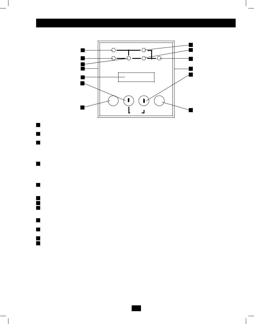
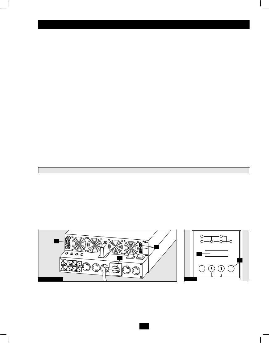
Front Panel Controls
I/P BYPASS
BATTERY AC/DC DC/AC O/P
ON |
OFF |
MUTE |
SELECT |
|
SETUP |
1LCD Display: This backlit dot matrix display indicates a wide range of UPS operating conditions and diagnostic data. It also displays UPS settings and options when the UPS is in setup mode.
2“ON/MUTE” Button: Press this button and hold it until you hear a beep to turn the UPS system's inverter ON. If the UPS's battery alarm is sounding, press this button to silence it.
3Scroll Down Button: This button allows you to browse through different options and power readings on the LCD display. Momentarily pressing it causes the LCD screen to display a different power reading (see “Operation” section). Pressing it and the SCROLL UP Button together puts the UPS in setup mode, where this button is used to scroll through setup options and to exit setup mode. Pressing the SCROLL UP and SCROLL DOWN buttons simultaneously for longer than one second while the UPS is in "ON BATTERY MODE" allows you to change the output voltage of the UPS (refer to "Output Voltage Selection" in the "Operation"section for details).
4Scroll Up/“SELECT” Button: This button allows you to browse through different options and power readings on the LCD display. Momentarily pressing it causes the LCD screen to display a different power reading (see "Operation" section). Pressing the SCROLL UP Button and SCROLL DOWN Button at the same time provides access to the configuration options of the UPS which include enabling or disabling the UPS "Economy Mode" feature or changing the output voltage of the UPS. (Refer to "Configuration Menu" in the "Operation" section for details.)
5“OFF” Button: Press this button and hold it until you hear a beep. The UPS will display the following message: "Switch to Bypass N(ON)/Y(OFF)" if it is safe to do so. Pressing OFF again will put the UPS in Bypass, still providing power to any connected equipment, but will not support a loss of utility power.
6“O/P” (Output) LED: This green light will illuminate to indicate your UPS is supplying AC power to connected equipment.
7“DC/AC” (Inverter) LED: This green light will illuminate to indicate the UPS's DC/AC inverter is activated.
8“BYPASS” LED: The BYPASS LED will illuminate a solid amber when the UPS is running in Economy Mode or flash amber if the UPS is in a BYPASS state. This amber light will flash when the UPS is providing filtered mains power without engaging its converter or inverter. If this LED is flashing, connected equipment will not receive battery power in the event of a blackout.
9“AC/DC” (Converter) LED: This green light will illuminate to indicate the UPS's AC/DC converter is charging the connected battery pack(s).
10“BATTERY” LED: This red light will illuminate when the UPS is discharging the battery to provide connected equipment with AC power. An alarm will sound which can be silenced by pressing the ON/MUTE Button. This LED will remain lit after the alarm is silenced.
11“I/P” (Input) LED: This green light will illuminate to indicate an AC input supply is present.
12Access Slots: To rotate the controls, insert a flathead screwdriver into these slots and gently lever the panel out. Taking care not to excessively twist or yank the cables connecting the controls to the rest of the UPS, turn the controls to the desired orientation and reinsert them.
3
201102170 932611.indd 3 |
3/30/2011 10:22:09 AM |

Features (continued)
Rear Panel Features (Power/Battery Module and Detachable PDU Together)
5
5 6
9
 8 9
8 9
7
10 |
10 |
11 |
|
SU6000RT4U Shown (Rear View) |
12 |
|
|||
|
10 |
|||
|
|
 Power/Battery Module: This self-contained unit houses the UPS system's power and control components as well as its internal batteries.
 Independent, Detachable Power Distribution Unit (PDU): This self-contained unit houses the UPS system's input and output components along with a bypass switch. When the switch is set to bypass, the PDU can be completely removed from the power/battery module for routine power/battery module maintenance without disrupting power to connected loads. While this switch is set to BYPASS, connected equipment will receive unfiltered AC mains power, but the equipment will not receive battery power in the event of a blackout. An optional hardwire detachable PDU is also available separately from Tripp Lite. Contact Tripp Lite for details. Note: The rotary bypass switch should only be operated while the UPS is in BYPASS Mode. (See section “Manual Bypass Operation” on page 8 for details.)
 External Battery Connector: Although the UPS includes a robust set of internal batteries, you may want to use this connector to attach one or more optional external battery packs (available separately from Tripp Lite) to the UPS for extended runtime. Check to ensure that the external batteries you are connecting match the voltage listed on your UPS's battery connector. Adding external batteries will increase recharge time as well as runtime. See the battery pack owner's manual for complete installation instructions. Make sure cables are fully inserted into their connectors. Small sparks may result during battery connection; this is normal. Do not connect or disconnect battery packs when the UPS is running on battery power.
 Battery Charge Level Switch (Select Models Only): Controls the UPS system's battery charge rate. If you connect any external batteries, set the Battery Charge Level Switch to the right (labeled “EXTERNAL BATTERIES”). This will increase your UPS's charger output so the additional batteries charge faster. CAUTION! DO NOT set the Battery Charge Level Switch to the right (labeled “EXTERNAL BATTERIES”) without an external battery connected. There is a risk of damaging the UPS's internal battery system.
 Ventilation Fans: These fans cool and ventilate the inside of the UPS.
 USB and RS-232 Communication Ports: These USB and female RS-232 DB9 serial ports may be used to connect your UPS to a workstation or server. They are used with Tripp Lite software and the included USB or serial cable to monitor and manage the UPS remotely over a network and to automatically save open files and shut down equipment during a blackout. See “Optional Connection” for details.
 EPO (Emergency Power Off) Port: This port may be used to connect the power module to a contact closure switch to enable emergency power off. See “Optional Connection” section for details.
 Accessory Slot: Remove the slot's cover to install an optional internal SNMP/Web accessory card (Model: SNMPWEBCARD) to enable remote UPS monitoring and control via SNMP, Web or telnet. Visit Tripp Lite on the Web (www.tripplite.com) to learn about available SNMP, network management and connectivity products that may be installed in this slot.
 AC Output Breakers: These breakers control output power from the independent, detachable PDU.
 AC Receptacles: Your UPS features 15-, 20and 30-amp AC outlets. These output receptacles provide your connected equipment with AC line power during normal operation and battery power during blackouts and severe brownouts and overvoltages. The UPS protects equipment connected to these receptacles against damaging surges and line noise. If you have a serial or USB connection to your UPS, you can remotely reboot connected equipment by turning the receptacles OFF and ON using Tripp Lite's PowerAlert Software. See software instructions for details.
 AC Input: Connects the UPS system to a utility wall outlet. Your UPS must be connected to a dedicated circuit of sufficient amperage.
Note: Model SU8000RT4U has a hardwire input instead of an input cord/plug
 Maintenance Bypass Switch: This switch allows qualified service personnel to remove the detachable PDU from the power/battery module for routine maintenance without disrupting power to connected loads. While this switch is set to BYPASS, connected equipment will receive filtered AC mains power, but the equipment will not receive battery power in the event of a blackout. See “Manual Bypass Operation” section for complete bypass procedure.
WARNING! For qualified service personnel only. Failure to follow the bypass procedure completely (see Manual Bypass Operation section) will not adequately power down the UPS power/battery module, resulting in the continued risk of death or
injury from potential contact with high voltage.
4
201102170 932611.indd 4 |
3/30/2011 10:22:10 AM |
Mounting
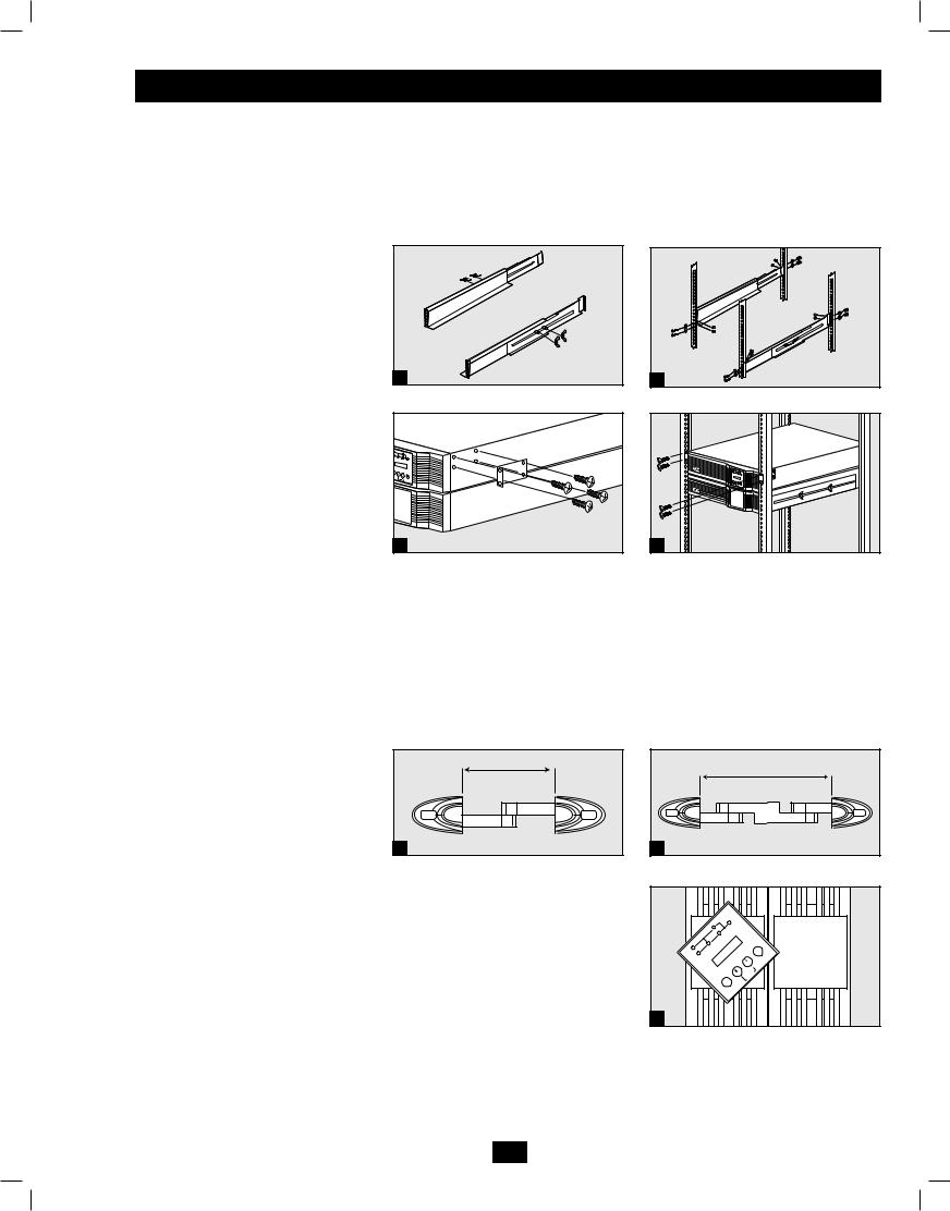
Mounting (4-Post Rackmount)
The UPS includes rackmount rails for 4-post rackmounting. The user must determine the fitness of hardware and procedures before mounting. If hardware and procedures are not suitable for your application, contact the manufacturer of your rack or rack enclosure. The procedures described in this manual are for common rack and rack enclosure types and may not be appropriate for all applications.
WARNING! The UPS system is extremely heavy. Use caution when lifting and mounting. User must properly stabilize the UPS when lifting and mounting.
 Connect the two segments of each shelf using the included attached screws and wing nuts. Leave the screws slightly loose so that the shelves can be adjusted in the next step.
 Adjust each shelf to fit your rack, then mount them in the lowest available space of your rack with the screws, nuts and washers provided. Note that the support ledges should face inward. Tighten the wingnuts that connect the shelf segments.
 Attach mounting ears to the front mounting holes of your UPS using the screws provided. The ears should face forward.
 Using one or more assistants, lift your UPS and slide it onto the mounting shelves. Attach your UPS to the rack by passing screws, nuts and washers (userprovided) through its mounting ears and into the rack rails.
1 |
3 |
2 |
4 |
Mounting (2-Post Rackmount)
If you mount this UPS model in 2-post racks, it requires the addition of a Tripp Lite 2-Post Rackmount Installation Kit (model: 2POSTRMKITWM, sold separately). See Installation Kit owner's manual for installation procedure.
Mounting (Tower)
Mount the UPS system in an upright, tower position using 2-9USTAND base stands (optional). The user must determine the fitness of hardware and procedures before mounting.
WARNING! The UPS system is extremely heavy. Use caution when lifting and mounting. User must properly stabilize the UPS when lifting and mounting.
 Adjust the stands to a width of 6.93 inches (176 mm) for a UPS. Adjust the stands to a width of 12.07 inches (306.5 mm) for a UPS and an external battery module. Align the stands approximately 10 inches (254 mm) apart. Have one or
more assistants help you place the UPS 1 on its side in the stands. Place the UPS
so that its control panel is on top and facing outward.
 Rotate the UPS's control panel to view iteasierwhiletheUPSistowermounted. Insert a small screwdriver, or other tool, in the slots on either side of the control panel. Pop the panel out; rotate it; and pop the panel back into place.
1 Power Module
6.93" (176 mm)
1 Power Module +
1 Battery Module
|
|
12.07" (306.5 mm) |
1 |
|
|
|
SS |
|
|
YPA |
/P |
|
B |
O |
|
C |
|
|
C/A |
|
|
D |
|
I/P |
C |
|
/D |
|
|
|
AC |
FF |
|
ERY |
|
|
O |
|
|
TT |
|
|
BA |
CT |
|
|
|
|
|
LE |
|
|
SE |
|
|
TUP |
|
|
SE |
|
ON |
E |
|
|
UT |
|
|
M |
2 |
|
|
5
201102170 932611.indd 5 |
3/30/2011 10:22:11 AM |
Connection
Note: The output voltage is set at 208/120V~ when the UPS is shipped from the factory. If you need to change the output voltage of the UPS, refer to “Output Voltage Selection” in the “Operation” section. You should select the correct output voltage before connecting your equipment to the UPS.
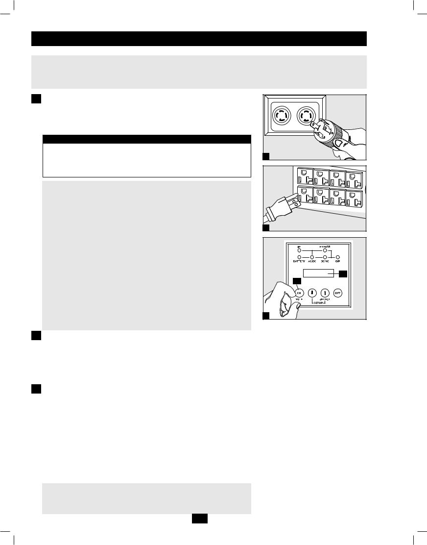
1 Plug your UPS's line cord into an electrical outlet.
Your UPS must be connected to a dedicated circuit of sufficient amperage.
Note! After you connect the UPS to a live AC power source, the UPS (in “STANDBY MODE”) will automatically charge its batteries, but will not supply power to its outlets until it is turned on.
Input and Output Ratings
|
Input |
Maximum Rated Maximum Rated |
Typical |
||
Model |
Voltage |
|
Input Current |
Output Current |
Wire Size |
SU5000RT4U |
100-140V (L1-N: L2-N) |
20A |
30A |
N/A |
|
SU6000RT4U |
100-140V (L1-N: L2-N) |
24A |
30A |
N/A |
|
SU8000RT4U |
100-140V (L1-N: L2-N) |
34A |
40A |
8 AWG |
|
Model SU8000RT4U has a hardwire input instead of an input cord/plug. Remove the circular knockouts to route the input cabling to the AC input terminal block. Unscrew and remove the utility input terminal block cover to access the AC input terminals. Review the hardwiring cautions below before attempting to connect the UPS input.
Hardwiring Cautions (Model SU8000RT4U Only)
•Wiring must be done by a qualified electrician.
•When making wiring connections, observe the cable connection regulations appropriate to your area [e.g. National Electrical Code (NEC) in the U.S.] at all times. Be sure to install an easily accessible disconnect switch in your installation wiring so you may cut off the AC input of the UPS during fires and other emergencies. Ensure that cables are fitted with cable sleeves and are secured by connector clamps. Tighten connections with a torque of not less than 24-28 inchpounds (2.7-3.2 NM).
•Make sure that your equipment is properly grounded.
•Using cables of improper size may damage your equipment and cause fire hazards. Choose appropriate cabling and protection circuits to make wiring connections. Ground conductors must be the same size and type as the power conductors used.
•Refer to National Electrical Code (NEC) guidelines for proper wire gauge and output protection circuit requirements.
1 |
2 |
B |
A |
3 |
2 Plug your equipment into your UPS.
Your UPS is designed to support electronic equipment only. You will overload your UPS if the total VA rating for all the equipment you connect exceeds the UPS's Output Capacity. Do not connect household appliances or laser printers to the UPS's outlets. To find your equipment's VA ratings, look on their nameplates. If the equipment is listed in amps, multiply the number of amps by the input voltage (208V, 240V or 120V) to determine VA. (Example: 1 amp × 120V = 120 VA).
3 Turn the UPS on.
Press the UPS's “ON” Button  until you hear a beep to begin inverter operation. Your UPS will now provide output power through its AC outlets to connected equipment.Your UPS will perform a brief self-test and show the results on the LCD Display
  . See “Startup Self-Test” in the “Operation” section for the display sequence.*
* Cold Start: To use your UPS as a stand-alone power source when AC input power is unavailable (i.e. during a blackout), you can “cold start” your UPS and power connected equipment from the UPS's battery. Your UPS's battery must be at least partially charged for this operation to succeed. Press and hold the “ON” Button until you hear a beep to cold start your UPS. The LCD Display will show ON BATTERY MODE. Battery power will begin discharging. Some electronic equipment may draw more amps during startup; when cold starting, consider reducing the initial load on the UPS.
Note: UPS system will function properly upon initial startup; however, maximum runtime for the unit’s battery will only be accessible after it has been charged for 24 hours.
To Turn the UPS System OFF: Press the UPS's “OFF” Button until you hear a beep. The LCD Display will show “BYPASS MODE.”The UPS will continue to automatically charge its batteries as long as AC input power is present. To completely deactivate the UPS, unplug the UPS's line cord when the UPS system is in bypass mode.
6
201102170 932611.indd 6 |
3/30/2011 10:22:12 AM |
Optional Connection
The following connections are optional. Your UPS system will function properly without these connections.
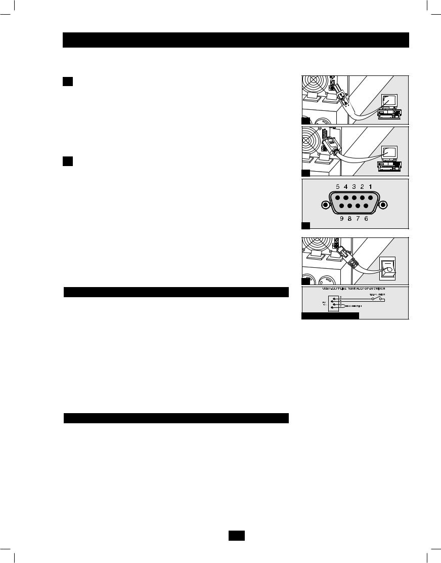
1 USB and RS-232 Serial Communication Connection
Use the included USB cable  and/or RS-232 DB9 serial cable
  to connect the communication port of your computer to the communication port of your UPS. Install on your computer the Tripp Lite PowerAlert Software appropriate to your computer's operating system. Consult your PowerAlert manual for more information.
Dry Contact Note: Dry contact communications are simple, but some knowledge of electronics is necessary to configure them. The DB9 port's pin assignments are shown in diagram  . If the UPS battery is low, the UPS sends a signal by bridging pins 1 and 5. If utility power fails, the UPS sends a signal by bridging pins 8 and 5. To shut the UPS down remotely, short pin 3 and pin 9 for at least 3.8 seconds.
2 EPO Port Connection
This optional feature is only for those applications that require connection to a facility’s Emergency Power Off (EPO) circuit. When the UPS is connected to this circuit, it enables emergency shutdown of the UPS’s inverter and inhibits transfer to internal bypass. Using the cable provided, connect the EPO port of your UPS (see  ) to a user-supplied normally closed or normally open switch according to the circuit diagram (see
  ).
).
Note:
1.If using a cable other than what is supplied, the cable should not exceed 350 feet or have a resistance of greater than 10 ohms.
2.If a non-latching EPO switch is used, the EPO must be held for a minimum of 1 second. This does not apply to a latching EPO switch.
CAUTION: The EPO port is not a phone line surge suppressor; do not connect a phone line to this port.
UPS Unit State when asserting EPO with AC line present:
LEDs |
Output |
Fans |
Serial |
SNMP |
USB |
LCD Screen |
|
OFF |
OFF |
ON |
ON |
ON |
ON |
“Emergency |
|
Stop” |
|||||||
|
|
|
|
|
|
To restart the UPS unit after asserting EPO with AC line present:
Option 1:
1.Verify that the EPO assertion has been removed or cleared.
2.Press ON button until unit displays "STAND BY" (approx. 1 second).
3.Press ON button again and UPS output will turn back on after it completes diagnostics.
Option 2:
1.Verify that the EPO assertion has been removed or cleared.
2.Remove AC line power to the UPS unit.
3.Reapply AC line power. Now the UPS will start back up in normal operation mode.
UPS Unit State when asserting EPO without AC line power:
LEDs |
Output |
Fans |
Serial |
SNMP |
USB |
LCD Screen |
|
OFF |
OFF |
OFF |
OFF |
OFF |
OFF |
“Emergency |
|
Stop” |
|||||||
|
|
|
|
|
|
To restart the UPS unit after asserting EPO without AC line power:
1.Verify that the EPO assertion has been removed or cleared.
2.Reapply AC line power to the UPS unit. Now the UPS will start back up in normal operation mode.
1a |
1b |
1c |
2a |
2b EPO Pin Assignment |
7
201102170 932611.indd 7 |
3/30/2011 10:22:12 AM |
Optional Connection (continued)
3 External Battery Connection
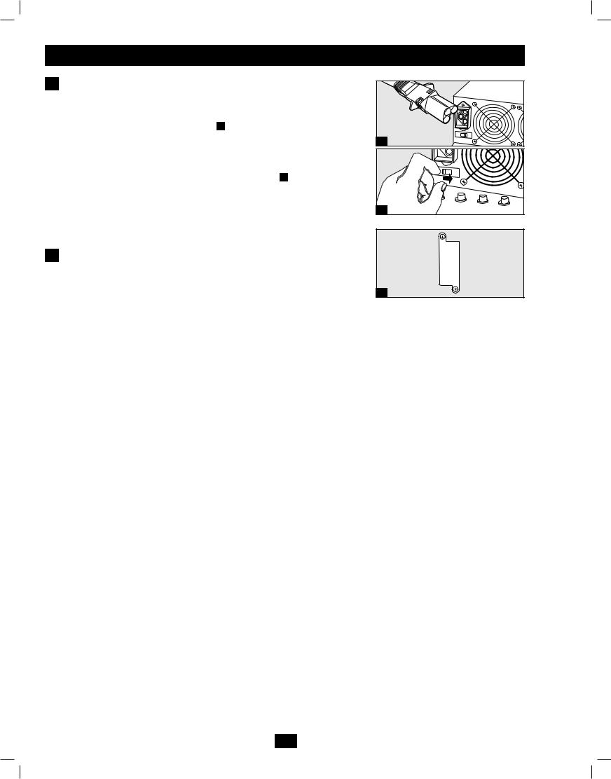
Your UPS comes with a robust internal battery system; external batteries are needed only to extend runtime. Adding external batteries will increase recharge time as well as runtime. The illustration shows the location of your UPS's External Battery Connector, where you will insert the battery pack cable 3a. Complete installation instructions for your battery pack appear in the battery pack owner's manual. Make sure that cables are fully inserted into their connectors. Small sparks may result during battery connection; this is normal. Do not connect or disconnect battery packs when the UPS is running on battery power.
NOTE: Select models feature a Battery Charge Level Switch 3b. If you connect any external batteries to these models, set the Battery Charge Level Switch (see diagram) to the right (labeled “EXTERNAL BATTERIES”). This will increase your UPS's charger output so the additional batteries charge faster.
CAUTION! DO NOT set the Battery Charge Level Switch to the right (labeled “EXTERNAL BATTERIES”) without an external battery connected. There is a risk of damaging the UPS's internal battery system.
4 Internal SNMP/WEB Card Insertion
Remove the slot's cover to install an optional internal SNMP/Web accessory card (Model: SNMPWEBCARD) to enable remote UPS monitoring and control via SNMP, Web or telnet. Contact Tripp Lite Customer Support at (773) 869-1234 for more information, including a list of available SNMP, network management and connectivity products.
|
SU6000RT4U |
3a |
Shown (Rear View) |
3b |
4
8
201102170 932611.indd 8 |
3/30/2011 10:22:13 AM |
Manual Bypass Operation (for UPS maintenance or replacement)
WARNING! For qualified service personnel only. Failure to follow the bypass procedure completely will not adequately power down the UPS power/battery module, resulting in the continued risk of death or injury from potential contact with high voltage. The UPS's power/battery module and detachable PDU are extremely heavy. This procedure requires several people to perform.
The UPS system includes a self-contained power/battery module along with an independent, detachable PDU with a bypass switch. This switch allows qualified service personnel to remove the detachable PDU from the power/battery module for routine maintenance without disrupting power to connected loads. While this switch is set to “BYPASS”, connected equipment will receive unfiltered AC mains power, but the equipment will not receive battery power in the event of a blackout.
Note: An optional detachable PDU with hardwire input/output is also available separately from Tripp Lite. Contact Tripp Lite for details.
(Optional: During a hot-swap, the PDU can be housed in the back of the rack configuration using supplied PDU hanger brackets and hardware. See STEP 1 below for mounting instructions.)
UPS Power/Battery Module Removal
STEP 1. (Optional) Attach a PDU hanger bracket to the right and left side, rear mounting rails using included screws and cage nuts. Important: determining where to attach your PDU hanger brackets will depend on your rack configuration. Generally it is recommended to mount the brackets in a U space close to where the UPS and PDU are mounted in. Be sure to mount both left and right brackets in the same U space on each side.
STEP 2. Disable PowerAlert Software and disconnect communication cable(s) from the communication port(s)  on the UPS power/ battery module.
STEP 3. Press the UPS's “OFF” Button  , if the UPS is powered, until you hear a beep and see a "Switch to Bypass N(NO)/Y(OFF)" message shown in the LCD Display
  . To continue, press the OFF button. If the bypass voltage is out of range, the unit will display "Bypass Out of Range, Unable to Bypass" and will cancel the request. Repeat this procedure. If the error persists, contact Customer Support.
STEP 4. Turn the detachable PDU's Bypass Switch  to “BYPASS”.
STEP 5. If an external battery module is connected to the UPS  , disconnect it from the UPS.
The UPS power/battery module is now safely powered down and it can be detached from the PDU to perform maintenance/replacement.
STEP 6: Remove the five screws that hold the detachable PDU to the power/battery module.
 WARNING! High Voltage! Risk of electrical shock! SEE PAGE 9.
STEP 7: Using several assistants at each end, carefully pull the detachable PDU away from the power/battery module. During this process, ensure that each section is properly supported after they are separated.
•If the sections are detached in a rackmount application, ensure that each section remains adequately supported by the UPS's rackmount rails. Remove the rackmounting hardware from the front panel of the UPS; slide the power/battery module forward, and remove. The PDU will remain supported on the rackmount rails. Care should be taken in this process because the PDU will not be secured to the rack with hardware of any kind.
•If it is desired to leave the detached PDU in the rack, hang the unit in back of the rack on the installed PDU hanger brackets by the screws used to attach the PDU to the UPS system.
•If the sections are detached in a tower application, ensure that the PDU is supported by the UPS's tower feet. Adjust the tower feet so they are as close together as possible.
To reattach the PDU, reverse the process listed above.
|
I/P |
|
BYPASS |
|
E |
|
|
|
|
|
BATTERY |
AC/DC |
DC/AC |
O/P |
|
A |
|
|
|
|
C |
|
|
|
|
D |
|
|
B |
|
|
|
|
|
|
ON |
|
|
OFF |
|
MUTE |
|
SELECT |
|
|
|
SETUP |
|
|
Steps 2, 4 & 5 |
Step 3 |
|
|
|
9
201102170 932611.indd 9 |
3/30/2011 10:22:14 AM |

Manual Bypass Operation (for UPS maintenance or replacement)
WARNING! High Voltage! Risk of electrical shock! SEE BELOW.
|
See Warning |
|
Statements |
Step 6 |
Below! |
Step 7 |
|
|
Step 7 |
 High Voltage Warnings
Contacts on Power/Battery Module
WARNING!
High Voltage! Risk of electrical shock!
Due to the presence of high voltage internal batteries, even without AC present, these contacts A are live!
Do not let these contacts touch any surface!
Contacts on Detachable PDU
WARNING! High voltage!
Risk of electrical shock!
If AC is present and Bypass Switch is set to “Bypass”, these contacts B are live!
Do not let these contacts touch any surface!
B
A
10
201102170 932611.indd 10 |
3/30/2011 10:22:15 AM |
Operation
The user can enter the Setup Mode at anytime (except during the Diagnostic Mode) by pushing both scroll buttons at the same time for more than 1 second. The Setup procedure is as follows:
Startup Self-Test
When you turn the UPS ON, it will enter Diagnostic Mode and perform a self-test lasting about 15 seconds. The results of the self-test are shown on the LCD screen in the sequences below.
LCD Screen Message Sequence |
LCD Screen Message Sequence |
(If UPS Is Started with AC Input) |
(If UPS Is “Cold-Started” with No AC Input) |
DIAGNOSTIC MODE
FREQ OUT = XXHz
DIAGNOSTIC MODE
INPUT AC OK
DIAGNOSTIC MODE
BATTERY OK
DIAGNOSTIC MODE
CHARGER OK
DIAGNOSTIC MODE
AC/DC OK
DIAGNOSTIC MODE TESTING INVERTER
UPS MODE
LOAD1 = XXX% X.XKW
DIAGNOSTIC MODE
FREQ OUT = XXHz
DIAGNOSTIC MODE INPUT AC BAD
DIAGNOSTIC MODE
BATTERY OK
DIAGNOSTIC MODE
AC/DC OK
DIAGNOSTIC MODE TESTING INVERTER
ON BATTERY MODE LOAD1 = XXX% X.XKW
Failed Self-Test
If a problem is detected during the self-test, the LCD will display an error message. If your UPS displays any of the following messages in its LCD, call Tripp Lite Technical Support at (773) 869-1234 for service.
LCD Screen Messages
(If UPS Fails Self-Test)
BAD BATTERY!
CALL FOR SERVICE
CHARGER FAILURE!
CALL FOR SERVICE
AC/DC FAILURE!
CALL FOR SERVICE
INVERTER FAILURE!
CALL FOR SERVICE
OUTPUT FAILURE!
CALL FOR SERVICE
FAN FAILURE!
CALL FOR SERVICE
11
201102170 932611.indd 11 |
3/30/2011 10:22:16 AM |

Operation (continued)
Normal Operation
During normal operation, the first line of your LCD Display shows which operating mode your UPS is in: “UPS MODE”, “ON BATTERY MODE”, “BYPASS MODE” or “STANDBY MODE”.
“UPS MODE”: The UPS provides AC power while utility power is available and switches to ON BATTERY MODE instantly (zero transfer time) if AC power is interrupted.
“ON BATTERY MODE”: The UPS provides AC power from battery backup so long as battery power lasts. It switches back to UPS MODE if utility power is available and shuts down if it runs out of battery power.
“STANDBY MODE”: The UPS is plugged in, charging it’s batteries and receiving AC power. However, it has not been turned on. “BYPASS MODE”: The UPS provides AC power while utility power is available. The UPS shuts down if AC power is interrupted.
The second line of the LCD Display shows basic power conditions. Push the SCROLL buttons to browse through these basic power conditions in the sequence shown below.
XXXX MODE
LOAD1 = XXX% X.XKW
XXXX MODE
LOAD2 = XXX% X.XKW
XXXX MODE
IN = XXXV XX.X Hz
XXXX MODE
IN1 = XXXV XX.X Hz
XXXX MODE
IN2 = XXXV XX.X Hz
XXXX MODE
OUT = XXXV XX.X Hz
XXXX MODE
OUT1 = XXXV XX.X Hz
XXXX MODE
OUT2 = XXXV XX.X Hz
XXXX MODE
BATT = XXXVDC XXX%
On Battery Alarm
When in the ON BATTERY MODE, the UPS power module will beep to inform you that it is using battery power to support connected equipment. If its connected batteries are at more than half capacity, it will beep every two seconds. If its connected batteries are below half capacity, it will beep twice per second. If its connected batteries are nearly depleted, the UPS power module will beep continuously. To silence the On Battery Alarm, press the “ON/MUTE” Button.
12
201102170 932611.indd 12 |
3/30/2011 10:22:16 AM |
Operation (continued)
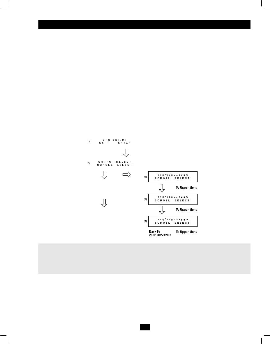
Configuration Menu
The UPS output voltage is set at 208/120V~ when the UPS is shipped from the factory. In order to change the output voltage of the UPS, you first need to enter “ON BATTERY MODE” by cold-starting the UPS. (The battery must be at least partially charged for this operation to succeed.) If the UPS is on, press and hold the “OFF” button until you hear a beep, disconnect any connected equipment and disconnect the UPS from its AC power input. After the UPS is disconnected from AC power, press the “ON/MUTE” button until you hear a beep. The LCD screen will show “ON BATTERY MODE” and an alarm will sound periodically to inform you that the UPS is using battery power. Silence the alarm by pressing the “ON/MUTE” button.
After the UPS has entered “ON BATTERY MODE”, press the SCROLL UP and SCROLL DOWN buttons simultaneously for longer than 1 second. The UPS will beep and the LCD will show the SET-UP screen(1). Press the SCROLL UP/SELECT button to enter the “UPS SET-UP” procedure(2). Press the SCROLL UP/SELECT button again to enter the “OUTPUT SELECT” procedure(3). There are 3 output voltage selections. Press the SCROLL DOWN button to scroll to the desired output voltage selection (3)-(5) and then press the SCROLL UP/SELECT button to select it. The LCD will return to the “OUTPUT SELECT” screen(2). Press the SCROLL DOWN button to reach the SET-UP screen(1) and press the SCROLL DOWN button again to exit the SET-UP procedure. The LCD should be back to “ON BATTERY MODE”. Press the “OFF” key until you hear a beep, and the UPS will save the selected output voltage parameter. Restore the AC power input of the UPS and press the “ON” key to turn on the UPS and use the SCROLL DOWN button to scroll through the basic power conditions displays and confirm that the output voltage has been changed to the desired value.
Economy Mode (ECO) is a high-efficiency operating mode in which the double conversion process is suspended. Incoming power is filtered, and if the input voltage is within +/- 10% of the nominal voltage, it is passed through to connected equipment. If the input voltage goes outside of this acceptable range, the unit automatically returns to its Online Mode to provide a highly regulated output derived from the system’s inverter. If voltage subsequently returns to the acceptable range, the unit will return to its high efficiency mode.
|
|
|
|
|
|
|
|
|
|
|
|
|
|
|
|
|
|
|
ECO |
Disable |
|
Scroll |
Select |
|
|
|
|
|
|
|
ECO |
Enable |
|
Exit |
Select |
|
|
|
Note:
208 / 120V<120D Output Voltage (L1-L2)=208V, Output Voltage (L1,L2)=120V and L1 leads L2 120 degrees 208 / 120V<240D Output Voltage (L1-L2)=208V, Output Voltage (L1,L2)=120V and L2 leads L1 120 degrees 240 / 120V<180D Output Voltage (L1-L2)=240V, Output Voltage (L1,L2)=120V and L1 leads L2 180 degrees
Additional Self-Test
If a self-test is initiated after startup, the LCD will display a message.
|
|
|
|
Self-Test Is Running |
|
TESTING BATTERY |
|
|
LOAD1 = XXX% X.XKW |
|
|
|
|
|
|
|
|
|
|
|
|
|
|
13
201102170 932611.indd 13 |
3/30/2011 10:22:17 AM |

Operation (continued)
Overload Messages
When the UPS detects an output overload, its LCD will switch to the following display:
OVERLOAD!
LOAD1 = XXX% X.XKW
OVERLOAD!
LOAD2 = XXX% X.XKW
The UPS will then begin a countdown. If the UPS is still overloaded at the end of the countdown, the UPS will automatically go to BYPASS MODE to protect its inverter. The duration of the countdown varies with the severity of the overload, as follows:
Overload Condition |
Countdown Duration |
102% - 125% |
1 minute |
|
|
125% - 150% |
30 seconds |
> 150% |
Immediate Bypass |
|
|
Bypass Messages
While in BYPASS MODE, the UPS monitors its input voltage and passes that input power along to connected equipment. The UPS will not provide battery backup in BYPASS MODE. If the output voltage deviates from an acceptable range (between 15% higher and 20% lower than nominal), the UPS displays the condition on its LCD and stops supplying output power to its load.
Bypass Voltage Conditions |
LCD Screen Messages |
L1 > 15% Higher |
BYPASS AC1 HIGH |
|
Than Nominal Voltage |
LOAD1 = XXX% X.XKW |
|
|
|
|
|
|
|
L2 > 15% Higher |
|
|
BYPASS AC2 HIGH |
|
|
Than Nominal Voltage |
LOAD1 = XXX% X.XKW |
|
|
|
|
|
|
|
L1 > 20% Lower |
|
|
BYPASS AC1 LOW |
|
|
Than Nominal Voltage |
LOAD1 = XXX% X.XKW |
|
|
|
|
|
|
|
L2 > 20% Lower |
|
|
BYPASS AC2 LOW |
|
|
Than Nominal Voltage |
LOAD1 = XXX% X.XKW |
|
|
|
|
|
|
|
|
|
|
L1 Voltage Was Too High, |
BYPASS AC1 WAS HI |
|
Now Returned to Nominal Voltage |
LOAD1 = XXX% X.XKW |
|
|
|
|
|
|
|
|
|
|
L2 Voltage Was Too High, |
BYPASS AC2 WAS HI |
|
Now Returned to Nominal Voltage |
LOAD1 = XXX% X.XKW |
|
|
|
|
|
|
|
|
|
|
L1 Voltage Was Too Low, |
BYPASS AC1 WAS LO |
|
Now Returned to Nominal Voltage |
LOAD1 = XXX% X.XKW |
|
|
|
|
|
|
|
|
|
|
L2 Voltage Was Too Low, |
BYPASS AC2 WAS LO |
|
Now Returned to Nominal Voltage |
LOAD1 = XXX% X.XKW |
|
|
|
|
14
201102170 932611.indd 14 |
3/30/2011 10:22:17 AM |

Operation (continued)
Shutdown Messages
Your UPS will shut down and the LCD will display a message if it detects one of the following conditions. Note: During all these conditions, the “Input,” “Output” and “Bypass” LEDs will be illuminated.
Shutdown Conditions |
LCD Screen Messages |
L1 Extended Overload |
SHUTDOWN |
|
L1 OVERLOAD=XXX% |
||
|
||
|
|
|
|
|
|
L2 Extended Overload |
SHUTDOWN |
|
L2 OVERLOAD=XXX% |
||
|
||
|
|
|
L1 to L2 |
|
|
OP SHORTCIRCUIT |
||
Output Short Circuit |
LOAD1 = XXX% X.XKW |
|
|
|
|
|
|
|
L1 to N Output Short Circuit |
OP1 SHORTCIRCUIT |
|
LOAD1 = XXX% X.XKW |
||
|
||
|
|
|
|
|
|
L2 to N Output Short Circuit |
OP2 SHORTCIRCUIT |
|
LOAD1 = XXX% X.XKW |
||
|
||
|
|
|
|
|
|
Remote Shutdown Command |
REMOTE COMMAND |
|
(via DB9) |
LOAD1 = XXX% X.XKW |
|
|
|
|
Remote Shutdown Command |
|
|
EMERGENCY STOP! |
||
(via EPO) |
LOAD1 = XXX% X.XKW |
|
|
|
|
|
|
|
Battery Depletion |
LOW BATTERY |
|
LOAD1 = XXX% X.XKW |
||
|
||
|
|
|
|
|
|
Site Wiring Fault |
SITE WIRING FAULT |
|
LOAD1 = XXX% X.XKW |
||
|
||
|
|
|
|
|
|
EEPROM Failure |
EEPROM FAIL |
|
LOAD1 = XXX% X.XKW |
||
|
||
|
|
|
|
|
|
Positive DC BUS Voltage |
+DC BUS HIGH |
|
is Too High |
LOAD1 = XXX% X.XKW |
|
|
|
|
|
|
|
Positive DC BUS Voltage |
+DC BUS LOW |
|
is Too Low |
LOAD1 = XXX% X.XKW |
|
|
|
|
Negative DC BUS Voltage |
|
|
-DC BUS HIGH |
||
is Too High |
LOAD1 = XXX% X.XKW |
|
|
|
|
|
|
|
Negative DC BUS Voltage |
-DC BUS LOW |
|
is Too Low |
LOAD1 = XXX% X.XKW |
|
|
|
|
|
|
|
Fan Failure |
FAN FAIL |
|
LOAD1 = XXX% X.XKW |
||
|
||
|
|
|
|
|
|
UPS Overtemperature |
OVERTEMPERATURE |
|
LOAD1 = XXX% X.XKW |
||
|
||
|
|
|
|
|
|
L1 Inverter Too High |
INVERTER1 HIGH |
|
LOAD1 = XXX% X.XKW |
||
|
||
|
|
|
|
|
|
|
|
|
L1 Inverter Too Low |
INVERTER1 LOW |
|
LOAD1 = XXX% X.XKW |
||
|
||
|
|
|
|
|
|
|
|
|
L2 Inverter Too High |
INVERTER2 HIGH |
|
LOAD1 = XXX% X.XKW |
||
|
||
|
|
|
|
|
|
|
|
|
L2 Inverter Too Low |
INVERTER2 LOW |
|
LOAD1 = XXX% X.XKW |
||
|
||
|
|
Shutdown Conditions |
LCD Screen Messages |
Internal Charger Failure |
INT CHARGER |
FAIL |
|
LOAD1 = XXX% |
X.XKW |
||
|
|||
|
|
|
|
|
|
|
|
External Charger Failure |
EXT CHARGER |
FAIL |
|
LOAD1 = XXX% |
X.XKW |
||
|
|||
|
|
||
|
|
|
|
Battery Open / Bad Battery |
BAD BATTERY! |
||
LOAD1 = XXX% |
X.XKW |
||
|
|||
|
|
||
Phase Lock Failure, |
|
|
|
BYPASS LOCKOUT |
|||
Bypass Lockout |
LOAD1 = XXX% |
X.XKW |
|
|
|
||
Phase Lock Failure, |
|
||
INVERTER LOCKOUT |
|||
Inverter Lockout |
LOAD1 = XXX% |
X.XKW |
|
15
201102170 932611.indd 15 |
3/30/2011 10:22:18 AM |
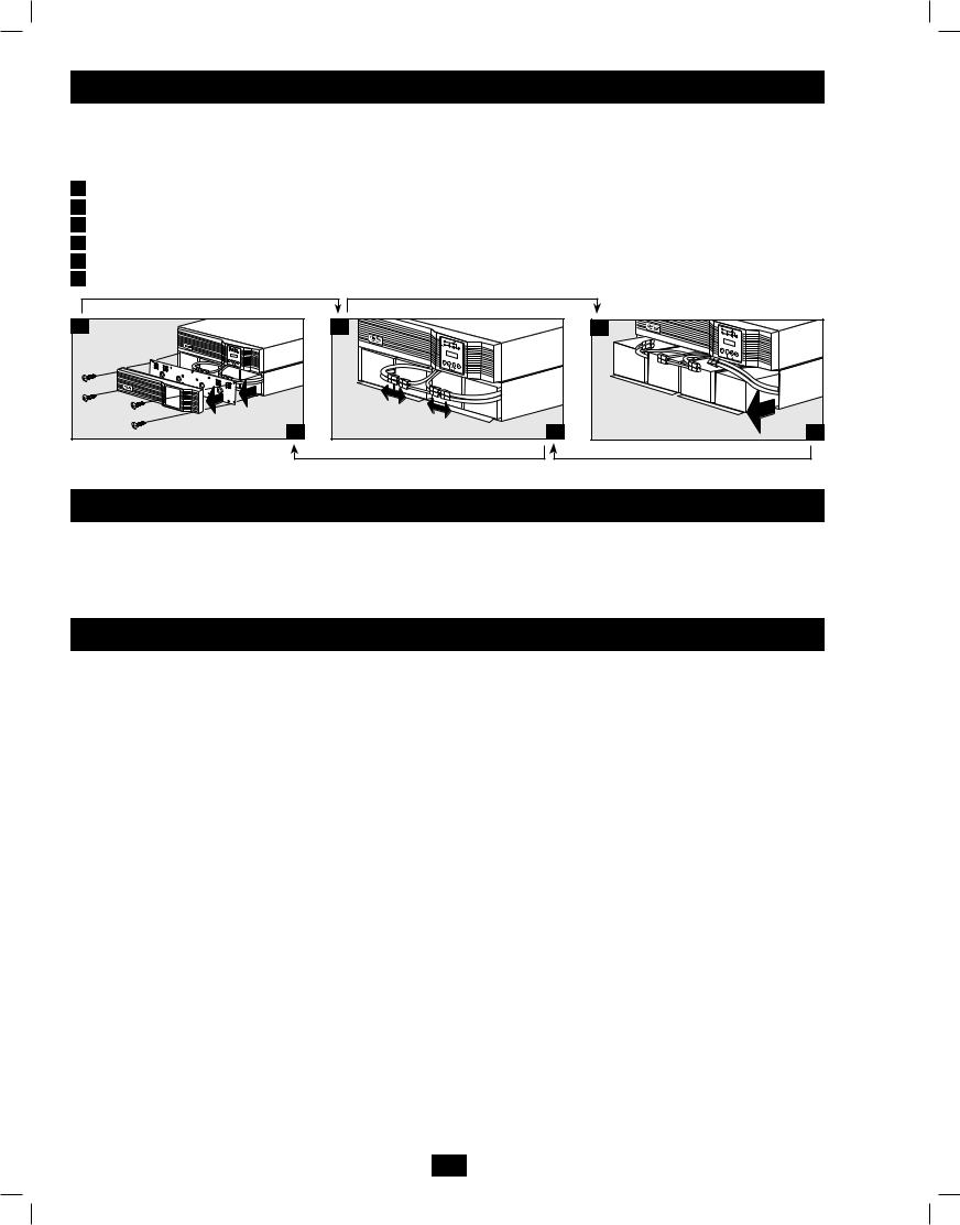
Internal Battery Replacement
Under normal conditions, the original batteries in your UPS will last many years. See Safety section before replacing batteries. The batteries are designed for hot-swap replacement (i.e. leaving the UPS ON), but some qualified service personnel may wish to completely turn the UPS OFF and disconnect equipment before proceeding.
1Remove Front Panel and Battery Cover Plate
2Disconnect Batteries
3Remove/Dispose of Batteries
4Add Batteries
5Connect Batteries. Attach connectors: black-to-black and red-to-red
6Replace Battery Cover Plate and Front Panel
1 |
6 |
2 |
5 |
3 |
4 |
Storage
Before storing your UPS, turn it completely OFF. If you store your UPS for an extended period of time, recharge the UPS batteries for 4 to 6 hours once every three months. Note: after you connect the UPS to utility power, it will automatically begin charging its batteries. If you leave your UPS batteries discharged for an extended period of time, they will suffer a permanent loss of capacity.
Service
Your Tripp Lite product is covered by the warranty described in this manual. A variety of Extended Warranty and On-Site Service Programs are also available from Tripp Lite. For more information on service, visit www.tripplite.com/support. Before returning your product for service, follow these steps:
1.Review the installation and operation procedures in this manual to insure that the service problem does not originate from a misreading of the instructions.
2.If the problem continues, do not contact or return the product to the dealer. Instead, visit www.tripplite.com/support.
3.If the problem requires service, visit www.tripplite.com/support and click the Product Returns link. From here you can request a Returned Material Authorization (RMA) number, which is required for service. This simple on-line form will ask for your unit’s model and serial numbers, along with other general purchaser information. The RMA number, along with shipping instructions will be emailed to you. Any damages (direct, indirect, special or consequential) to the product incurred during shipment to Tripp Lite or an authorized Tripp Lite service center is not covered under warranty. Products shipped to Tripp Lite or an authorized Tripp Lite service center must have transportation charges prepaid. Mark the RMA number on the outside of the package. If the product is within its warranty period, enclose a copy of your sales receipt. Return the product for service using an insured carrier to the address given to you when you request the RMA.
16
201102170 932611.indd 16 |
3/30/2011 10:22:18 AM |
 Loading...